VA 33 30 00 Sanitary Sewerage Utilities - WBDG NCA 33 30 00.pdf · SECTION 33 30 00 SANITARY...
23
11-01-16 SANITARY SEWERAGE UTILITES 33 30 00 - 1 SECTION 33 30 00 SANITARY SEWERAGE UTILITIES SPEC WRITER NOTES: 1. Use this section only for NCA projects. 2. Delete between // // if not applicable to project. Also delete any other item or paragraph not applicable in the section and renumber the paragraphs. 3. References to pressure in this section are gage pressure unless otherwise noted. PART 1 - GENERAL 1.1 DESCRIPTION A. Outside, underground sanitary sewer system, complete, ready for operation, including all gravity flow lines //pressure (force) lines// manholes, cleanouts, frames, covers, structures, appurtenances, and connections to new building and structure, service lines, existing sanitary sewer lines, and existing sanitary structures, and all other incidentals. 1.2 RELATED WORK SPEC WRITER NOTE: Retain one of two paragraphs below. A. //Section 01 00 01, GENERAL REQUIREMENTS (Major NCA Projects).// B. //Section 01 00 02, GENERAL REQUIREMENTS (Minor NCA Projects).// C. Section 01 33 23, SHOP DRAWINGS, PRODUCT DATA, AND SAMPLES. D. Section 01 42 19, REFERENCE STANDARDS. E. Section 01 81 13, SUSTAINABLE DESIGN REQUIREMENTS. F. //Section 01 91 00, GENERAL COMMISSIONING REQUIREMENTS.// G. //Section 03 30 53, (SHORT FORM) CAST-IN-PLACE CONCRETE.// H. Section 05 50 00, METAL FABRICATIONS: Fabrication of Steel Ladders. I. //Section 22 13 29, SANITARY SEWERAGE PUMPS.// J. //Section 31 20 00, EARTH MOVING:// //Section 31 20 11, (SHORT FORM) EARTH MOVING:// //Section 31 23 19, DEWATERING:// Excavation, Trench Widths, Pipe Bedding, Backfill, Shoring, Sheeting, Bracing. K. Section 32 90 00, PLANTING: Seeding, Topsoil. L. Section 33 10 00, WATER UTILITIES.
Transcript of VA 33 30 00 Sanitary Sewerage Utilities - WBDG NCA 33 30 00.pdf · SECTION 33 30 00 SANITARY...
11-01-16
SANITARY SEWERAGE UTILITES 33 30 00 - 1
SECTION 33 30 00 SANITARY SEWERAGE UTILITIES
SPEC WRITER NOTES: 1. Use this section only for NCA
projects. 2. Delete between // // if not
applicable to project. Also delete any other item or paragraph not applicable in the section and renumber the paragraphs.
3. References to pressure in this section are gage pressure unless otherwise noted.
PART 1 - GENERAL
1.1 DESCRIPTION
A. Outside, underground sanitary sewer system, complete, ready for
operation, including all gravity flow lines //pressure (force) lines//
manholes, cleanouts, frames, covers, structures, appurtenances, and
connections to new building and structure, service lines, existing
sanitary sewer lines, and existing sanitary structures, and all other
incidentals.
1.2 RELATED WORK
SPEC WRITER NOTE: Retain one of two paragraphs below.
A. //Section 01 00 01, GENERAL REQUIREMENTS (Major NCA Projects).//
B. //Section 01 00 02, GENERAL REQUIREMENTS (Minor NCA Projects).//
C. Section 01 33 23, SHOP DRAWINGS, PRODUCT DATA, AND SAMPLES.
D. Section 01 42 19, REFERENCE STANDARDS.
E. Section 01 81 13, SUSTAINABLE DESIGN REQUIREMENTS.
F. //Section 01 91 00, GENERAL COMMISSIONING REQUIREMENTS.//
G. //Section 03 30 53, (SHORT FORM) CAST-IN-PLACE CONCRETE.//
H. Section 05 50 00, METAL FABRICATIONS: Fabrication of Steel Ladders.
I. //Section 22 13 29, SANITARY SEWERAGE PUMPS.//
J. //Section 31 20 00, EARTH MOVING:// //Section 31 20 11, (SHORT FORM)
EARTH MOVING:// //Section 31 23 19, DEWATERING:// Excavation, Trench
Widths, Pipe Bedding, Backfill, Shoring, Sheeting, Bracing.
K. Section 32 90 00, PLANTING: Seeding, Topsoil.
L. Section 33 10 00, WATER UTILITIES.
11-01-16
SANITARY SEWERAGE UTILITES 33 30 00 - 2
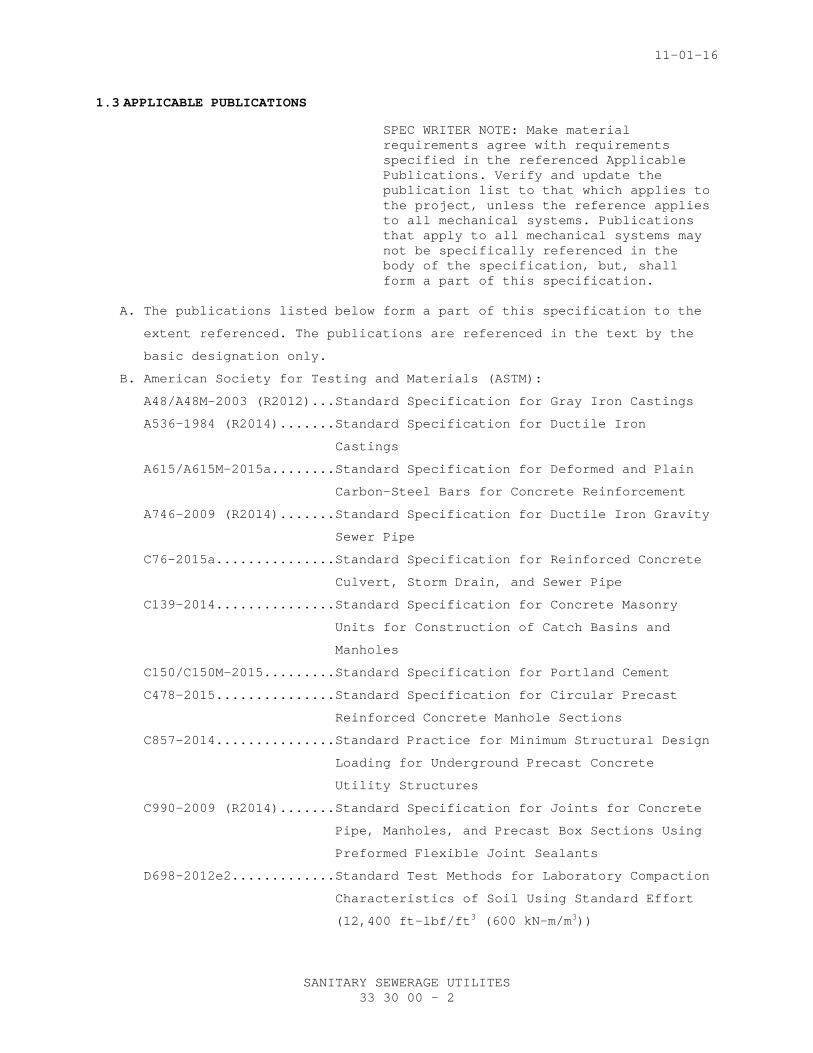
1.3 APPLICABLE PUBLICATIONS
SPEC WRITER NOTE: Make material requirements agree with requirements specified in the referenced Applicable Publications. Verify and update the publication list to that which applies to the project, unless the reference applies to all mechanical systems. Publications that apply to all mechanical systems may not be specifically referenced in the body of the specification, but, shall form a part of this specification.
A. The publications listed below form a part of this specification to the
extent referenced. The publications are referenced in the text by the
basic designation only.
B. American Society for Testing and Materials (ASTM):
A48/A48M-2003 (R2012)...Standard Specification for Gray Iron Castings
A536-1984 (R2014).......Standard Specification for Ductile Iron
Castings
A615/A615M-2015a........Standard Specification for Deformed and Plain
Carbon-Steel Bars for Concrete Reinforcement
A746-2009 (R2014).......Standard Specification for Ductile Iron Gravity
Sewer Pipe
C76-2015a...............Standard Specification for Reinforced Concrete
Culvert, Storm Drain, and Sewer Pipe
C139-2014...............Standard Specification for Concrete Masonry
Units for Construction of Catch Basins and
Manholes
C150/C150M-2015.........Standard Specification for Portland Cement
C478-2015...............Standard Specification for Circular Precast
Reinforced Concrete Manhole Sections
C857-2014...............Standard Practice for Minimum Structural Design
Loading for Underground Precast Concrete
Utility Structures
C990-2009 (R2014).......Standard Specification for Joints for Concrete
Pipe, Manholes, and Precast Box Sections Using
Preformed Flexible Joint Sealants
D698-2012e2.............Standard Test Methods for Laboratory Compaction
Characteristics of Soil Using Standard Effort
(12,400 ft-lbf/ft3 (600 kN-m/m3))
11-01-16
SANITARY SEWERAGE UTILITES 33 30 00 - 3
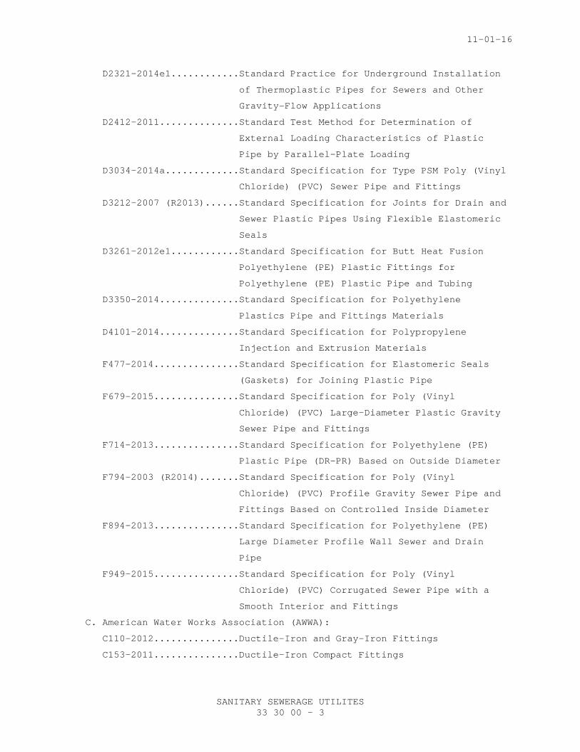
D2321-2014e1............Standard Practice for Underground Installation
of Thermoplastic Pipes for Sewers and Other
Gravity-Flow Applications
D2412-2011..............Standard Test Method for Determination of
External Loading Characteristics of Plastic
Pipe by Parallel-Plate Loading
D3034-2014a.............Standard Specification for Type PSM Poly (Vinyl
Chloride) (PVC) Sewer Pipe and Fittings
D3212-2007 (R2013)......Standard Specification for Joints for Drain and
Sewer Plastic Pipes Using Flexible Elastomeric
Seals
D3261-2012e1............Standard Specification for Butt Heat Fusion
Polyethylene (PE) Plastic Fittings for
Polyethylene (PE) Plastic Pipe and Tubing
D3350-2014..............Standard Specification for Polyethylene
Plastics Pipe and Fittings Materials
D4101-2014..............Standard Specification for Polypropylene
Injection and Extrusion Materials
F477-2014...............Standard Specification for Elastomeric Seals
(Gaskets) for Joining Plastic Pipe
F679-2015...............Standard Specification for Poly (Vinyl
Chloride) (PVC) Large-Diameter Plastic Gravity
Sewer Pipe and Fittings
F714-2013...............Standard Specification for Polyethylene (PE)
Plastic Pipe (DR-PR) Based on Outside Diameter
F794-2003 (R2014).......Standard Specification for Poly (Vinyl
Chloride) (PVC) Profile Gravity Sewer Pipe and
Fittings Based on Controlled Inside Diameter
F894-2013...............Standard Specification for Polyethylene (PE)
Large Diameter Profile Wall Sewer and Drain
Pipe
F949-2015...............Standard Specification for Poly (Vinyl
Chloride) (PVC) Corrugated Sewer Pipe with a
Smooth Interior and Fittings
C. American Water Works Association (AWWA):
C110-2012...............Ductile-Iron and Gray-Iron Fittings
C153-2011...............Ductile-Iron Compact Fittings
11-01-16
SANITARY SEWERAGE UTILITES 33 30 00 - 4
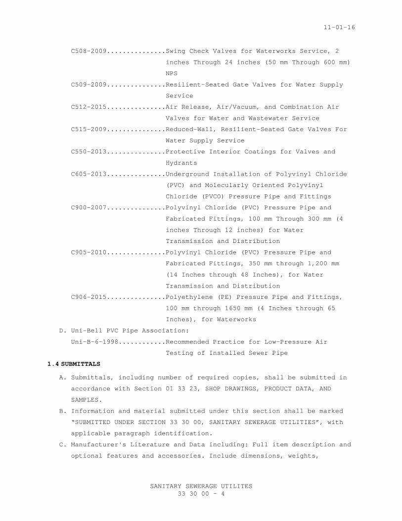
C508-2009...............Swing Check Valves for Waterworks Service, 2
inches Through 24 inches (50 mm Through 600 mm)
NPS
C509-2009...............Resilient-Seated Gate Valves for Water Supply
Service
C512-2015...............Air Release, Air/Vacuum, and Combination Air
Valves for Water and Wastewater Service
C515-2009...............Reduced-Wall, Resilient-Seated Gate Valves For
Water Supply Service
C550-2013...............Protective Interior Coatings for Valves and
Hydrants
C605-2013...............Underground Installation of Polyvinyl Chloride
(PVC) and Molecularly Oriented Polyvinyl
Chloride (PVCO) Pressure Pipe and Fittings
C900-2007...............Polyvinyl Chloride (PVC) Pressure Pipe and
Fabricated Fittings, 100 mm Through 300 mm (4
inches Through 12 inches) for Water
Transmission and Distribution
C905-2010...............Polyvinyl Chloride (PVC) Pressure Pipe and
Fabricated Fittings, 350 mm through 1,200 mm
(14 Inches through 48 Inches), for Water
Transmission and Distribution
C906-2015...............Polyethylene (PE) Pressure Pipe and Fittings,
100 mm through 1650 mm (4 Inches through 65
Inches), for Waterworks
D. Uni-Bell PVC Pipe Association:
Uni-B-6-1998............Recommended Practice for Low-Pressure Air
Testing of Installed Sewer Pipe
1.4 SUBMITTALS
A. Submittals, including number of required copies, shall be submitted in
accordance with Section 01 33 23, SHOP DRAWINGS, PRODUCT DATA, AND
SAMPLES.
B. Information and material submitted under this section shall be marked
“SUBMITTED UNDER SECTION 33 30 00, SANITARY SEWERAGE UTILITIES”, with
applicable paragraph identification.
C. Manufacturer's Literature and Data including: Full item description and
optional features and accessories. Include dimensions, weights,
11-01-16
SANITARY SEWERAGE UTILITES 33 30 00 - 5
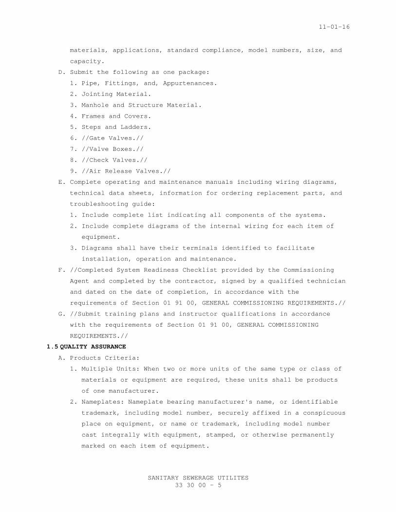
materials, applications, standard compliance, model numbers, size, and
capacity.
D. Submit the following as one package:
1. Pipe, Fittings, and, Appurtenances.
2. Jointing Material.
3. Manhole and Structure Material.
4. Frames and Covers.
5. Steps and Ladders.
6. //Gate Valves.//
7. //Valve Boxes.//
8. //Check Valves.//
9. //Air Release Valves.//
E. Complete operating and maintenance manuals including wiring diagrams,
technical data sheets, information for ordering replacement parts, and
troubleshooting guide:
1. Include complete list indicating all components of the systems.
2. Include complete diagrams of the internal wiring for each item of
equipment.
3. Diagrams shall have their terminals identified to facilitate
installation, operation and maintenance.
F. //Completed System Readiness Checklist provided by the Commissioning
Agent and completed by the contractor, signed by a qualified technician
and dated on the date of completion, in accordance with the
requirements of Section 01 91 00, GENERAL COMMISSIONING REQUIREMENTS.//
G. //Submit training plans and instructor qualifications in accordance
with the requirements of Section 01 91 00, GENERAL COMMISSIONING
REQUIREMENTS.//
1.5 QUALITY ASSURANCE A. Products Criteria:
1. Multiple Units: When two or more units of the same type or class of
materials or equipment are required, these units shall be products
of one manufacturer.
2. Nameplates: Nameplate bearing manufacturer's name, or identifiable
trademark, including model number, securely affixed in a conspicuous
place on equipment, or name or trademark, including model number
cast integrally with equipment, stamped, or otherwise permanently
marked on each item of equipment.
11-01-16
SANITARY SEWERAGE UTILITES 33 30 00 - 6
B. Comply with the rules and regulations of the Public Utility having
jurisdiction over the connection, extension, and modification to Public
Sanitary Sewer lines and Public Utility Systems as applicable.
1.6 AS-BUILT DOCUMENTATION
SPEC WRITER NOTE: Coordinate O&M Manual requirements with Section 01 00 01, GENERAL REQUIREMENTS (Major NCA Projects) or Section 01 00 02, GENERAL REQUIREMENTS (Minor NCA Projects). O&M manuals shall be submitted for content review as part of the close-out documents.
A. Submit manufacturer’s literature and data updated to include submittal
review comments and any equipment substitutions.
B. Submit operation and maintenance data updated to include submittal
review comments, substitutions and construction revisions shall be //in
electronic version on CD or DVD// inserted into a three ring binder.
All aspects of system operation and maintenance procedures, including
applicable piping isometrics, wiring diagrams of all circuits, a
written description of system design, control logic, and sequence of
operation shall be included in the operation and maintenance manual.
The operations and maintenance manual shall include troubleshooting
techniques and procedures for emergency situations. Notes on all
special systems or devices shall be included. A List of recommended
spare parts (manufacturer, model number, and quantity) shall be
furnished. Information explaining any special knowledge or tools the
owner will be required to employ shall be inserted into the As-Built
documentation.
C. The installing contractor shall maintain as-built drawings of each
completed phase for verification; and, shall provide the complete set
at the time of final systems certification testing. As-built drawings
are to be provided, and a copy of them in Auto-CAD version //____//
provided on CD or DVD. Should the installing contractor engage the
testing company to provide as-built or any portion thereof, it shall
not be deemed a conflict of interest or breach of the ‘third party
testing company’ requirement.
D. Certification documentation shall be provided to COR 10 working days
prior to submitting the request for final inspection. The documentation
shall include all test results, the names of individuals performing
work for the testing agency on this project, detailed procedures
11-01-16
SANITARY SEWERAGE UTILITES 33 30 00 - 7
followed for all tests, and certification that all results of tests
were within limits specified.
PART 2 - PRODUCTS
2.1 PIPING
A. Gravity Flow Lines (Pipe and Fittings):
1. Polyvinyl Chloride (PVC):
a. Pipe and Fittings, 100 mm to 381 mm (4 inches to 15 inches) in
diameter, shall conform to ASTM D3034, Type PSM, //SDR 35// //SDR
26//. Pipe and fittings shall have elastomeric gasket joints
providing a watertight seal when tested in accordance with ASTM
D3212. Gaskets shall conform to ASTM F477. Solvent welded joints
are prohibited.
b. Pipe and fittings, 450 mm to 900 mm (18 inches to 36 inches) in
diameter, shall be solid wall or have a corrugated or ribbed
exterior profile and a smooth interior. Pipe shall conform to the
following:
1) Pipe and fittings shall conform to ASTM F949 corrugated sewer
pipe with a smooth interior. The corrugated outer wall shall
be fused to the smooth innerwall at the corrugation valley.
Pipe and fitting shall have a smooth bell, elastomeric joints
conforming to ASTM D3212, and shall have a minimum pipe
stiffness of 345 kPa (50 psi) at 5 percent deflection when
tested in accordance with ASTM D2412. Corrugation shall be
perpendicular to the axis of the pipe to allow gaskets to be
installed on field cut sections of pipe without the
requirement for special fittings.
2) Ribbed wall PVC pipe and fittings shall conform to ASTM F794
ribbed sewer pipe with smooth interior pipe. Fittings shall
have a smooth bell, elastomeric joints conforming to ASTM
D3212, and shall have a minimum pipe stiffness of 320 kPa (46
psi) when tested in accordance with ASTM D 2412 at 5 percent
vertical deflection. Joints shall not leak at 7.6 m (25 feet)
of head under 5 percent deflection.
3) Solid wall pipe and fittings shall conform to ASTM F679, //SDR
35// //SDR 26// pipe. Fittings shall have gaskets conforming
to ASTM F477 and shall be able to withstand a hydrostatic
pressure of 345 kPa (50 psi).
11-01-16
SANITARY SEWERAGE UTILITES 33 30 00 - 8
2. High density polyethylene (HDPE) pipe and fittings 450 mm to 900 mm
(18 inches to 36 inches) shall conform to ASTM F894. Pipe and
fittings shall have a smooth interwall and profile exterior, and be
Class //40// //63// //100// //160// //as noted on the drawings//.
Joints shall be water tight elastomeric gaskets in accordance with
ASTM D3212, or thermal welded joints.
SPEC WRITER NOTE: Use fiberglass pipe for secondary containment for acid waste if required by local code.
B. Pressure (Force) Lines (Pipe and Fittings):
1. All pipe and fittings used in the construction of force mains shall
be rated for a minimum of //1035 kPa (150 psi)// // // kPa (//
// psi).
2. Polyvinyl Chloride (PVC): PVC pipe 100 mm to 300 mm (4 inches to 12
inches) shall conform to AWWA C900, //Class 150 (DR 18)// //Class
200 (DR 14)//. PVC pipe greater than 300 mm (12 inches) shall
conform to AWWA C905, //Class 165 (DR 25)// //Class 200 (DR 21)//.
Fittings for PVC pipe shall be ductile iron conforming to AWWA C153
or AWWA C110.
3. High Density Polyethylene (HDPE) pipe and fittings shall be
manufactured from PE 3608, high density, extra high molecular weight
polyethylene meeting the requirements of ASTM D3350. Pipe shall be
manufactured in accordance with ASTM F714, and shall be //Class 160
(DR 11)// //Class 200 (DR 9)//. Molded fittings shall be
manufactured in accordance with ASTM D3261 and subject to the test
required under ASTM D3261. Fabricated fittings shall be made by heat
fusion jointing of machined shapes cut from pipe, sheet stock, or
molded fittings. Molded and fabricated fittings shall be rated for a
minimum working pressure equivalent to the pipe. Joints shall be
heat fusion butt joints, flange adapters, or mechanical couplings.
a. Flange adapters shall have adequate through-bore length to be
clamped in a butt fusion jointing machine without the use of a
stub-end holder. The sealing surface of the flanged shall be
machined with a series of V-shaped grooves to restrain the gasket
against blow out. Back-up rings and flange bolts shall be rated
equal to or greater than the mating pipe. All flange adapters
shall be equipped with a stainless steel internal pipe stiffener.
b. Mechanical couplings shall be sleeve style, restrained coupling.
11-01-16
SANITARY SEWERAGE UTILITES 33 30 00 - 9
2.2 JOINTING MATERIAL
A. Gravity Flow Lines:
1. Polyvinyl Chloride (PVC) Pipe (Gravity Use): Joints, ASTM D3212.
Elastomeric gasket, ASTM F477.
2. High Density Polyethylene (HDPE) pipe and fitting joints, ASTM
D3212, elastomeric gaskets, ASTM F477.
B. Pressure (Force) Main:
1. Polyvinyl Chloride (PVC) Pipe (Pressure Use): Conform to AWWA C900.
a. Push-on joints shall conform to AWWA C900 and AWWA C905.
b. Push-on gaskets for pipe, ASTM F477.
c. Restrained joints shall comply with the following:
1) Push-on bell and spigot joints shall be retained with
retaining rings and thrust rods. The rings shall be ductile
iron conforming to ASTM A536.
2. High Density Polyethylene (HDPE) pipe and fittings shall be fusion
butt welded, flanged, or mechanical couplings as recommended by the
manufacturer. Restrained joints shall be limited to fusion welded
and flanged.
2.3 MANHOLES AND VAULTS
A. Manholes and vaults shall be constructed of precast concrete segmental
blocks, precast reinforced concrete rings, precast reinforced sections,
or cast-in-place concrete. The manholes and vaults shall be in
accordance with State Department of Transportation or State Roads
Commission standard details, and the following:
1. Precast Concrete Segmental Blocks: Blocks shall conform to ASTM C139
and shall not be less than 150 mm (6 inches) thick for manholes to a
depth of 3.6 m (12 feet); not less than 200 mm (8 inches) thick for
manholes deeper than 3.6m (12 feet) deep. Blocks shall be not less
than 200 mm (8 inches) in length. Blocks shall be shaped so that
joints seal and bond effectively with cement mortar. Cover structure
interior and exterior with 15 mm (1/2 inch) of cement mortar applied
with a trowel and finished to an even glazed surface.
2. Precast Reinforced Concrete Rings: Rings or sections shall have an
inside diameter as indicated on the drawings, and shall be not less
than 1219 mm (48 inches) in diameter. Wall thickness shall conform
to requirements of ASTM C478, except that lengths of the sections
may be shorter as conditions require. Tops shall conform to ASTM
C478. Top section shall be eccentric cone type. Steps on inside wall
11-01-16
SANITARY SEWERAGE UTILITES 33 30 00 - 10
shall be in the same plane from bottom of structure to manhole
cover.
3. Precast Reinforced Concrete Manhole Risers and Tops: Design,
material and installation shall conform to requirements of ASTM
C478. Top sections shall be eccentric. Steps on inside wall shall be
in the same plane from bottom of structure to manhole cover.
4. Flat top manhole tops shall be reinforced concrete as detailed on
the drawings.
5. Vaults: Reinforced concrete, as indicated on the plans, or precast
reinforced concrete. Concrete for precast sections shall have a
minimum compressive strength of 35 MPa (5,000 psi) at 28 days, ASTM
A615/A615M, Grade 60 reinforcing steel, rated for AASHTO HS20-44
loading with 30 percent impact, and conform to ASTM C857.
6. Mortar:
a. Precast Concrete Segmental Block Structures: By volume, 1 part of
Portland cement, l/4 part lime hydrate, and 3 parts sand.
b. Precast Reinforced Concrete Ring and Riser Structures: By volume,
1 part of Portland cement and 2 parts sand. Water in mixture
shall produce a stiff, workable mortar, but shall not exceed 21 L
(5-1/2 gallons) per sack of cement.
7. Flexible sealing compound shall be packaged in extruded preformed
shape, sized to completely fill the joint between precast sections,
and form permanently flexible watertight seal. The sealing compound
shall be non-shrink and meet ASTM C990.
8. Frames and covers shall be gray cast iron conforming to ASTM
A48/A48M. The frame and cover shall be rated for AASHTO HS20-44
loading, have a studded pattern on the cover, and the words
“sanitary sewer”. The studs and the lettering shall be raised 8 mm
(5/16 inch). The cover shall be a minimum of 600 mm (24 inches) in
diameter and shall have four 20 mm (3/4 inch) vent holes and two
lifting slots. The bearing surface of the frame and cover shall be
machine finished. The cover shall fit firmly on the frame without
movement when subject to traffic.
9. Manhole steps shall be polypropylene plastic coated on a No. 4
deformed rebar conforming to ASTM C478, Polypropylene shall conform
to ASTM D4101. Steps shall be a minimum of 400 mm (16 inches) wide
and project a minimum of 175 mm (7 inches) away from the wall. The
11-01-16
SANITARY SEWERAGE UTILITES 33 30 00 - 11
top surface of the step shall have a studded non-slip surface. Steps
shall be placed at 300 mm (12 inch) centers.
10. Ladders, brackets and hardware shall be constructed of welded
aluminum, rails shall be 10 mm (3/8 inch) by 65 mm (2-1/2 inches)
spaced a minimum of 400 mm (16 inches) apart. Rungs shall be 35 mm
(1-3/8 inches) in diameter and have a non-slip surface. Standoffs
shall offset the ladder 175 mm (7 inches) from the wall. The ladder
assembly shall be rated for a minimum of 2200 N (500 pounds).
2.4 CONCRETE
A. Concrete shall have a minimum compressive strength of 21 MPa (3000 psi)
at 28 days. The cement shall be Type III conforming to ASTM C150/C150M.
Concrete shall conform with the provisions of Division 03, CONCRETE.
2.5 REINFORCING STEEL
A. Reinforcing steel shall be deformed bars, ASTM A615/A615M, Grade 60
unless otherwise noted.
2.6 //SEWAGE WET WELL (LARGER THAN 300 GALLONS WORKING VOLUME)
A. Wet well shall be a rectangular precast vault conforming to ASTM C857.
The vault shall have a precast bottom, walls, and top structure. The
vault shall be constructed of 35 MPa (5000 psi) concrete at 28 days and
ASTM A615/A615M, Grade 60 reinforcement. The vault shall be rated for
AASHTO HS20-44 loading and 30 percent impact loads.
B. All joints in the precast structure shall be tongue and groove.
Flexible sealing compound, conforming to ASTM C990, shall be placed in
all joints to form a watertight structure.//
2.7 CONCRETE PROTECTIVE COATING
A. Concrete coating for the interior of wet wells shall consist of an
epoxy blended filler sealer, and a cross linked epoxy phenolic cured,
resistant protective coating.
2.8 GATE VALVES
A. AWWA C509, resilient seated gate valves rated for 1380 kPa (200 psi)
WSP, reduced-wall resilient seated gates valves may be supplied in
accordance with AWWA C515. Asbestos packing is prohibited. The interior
and exterior of the valve shall be epoxy coated for AWWA C550.
B. Operation:
C. Shall turn counterclockwise to open.
D. Underground: 50 mm (2 inch) nut for socket wrench operation.
E. Above Ground and In Pits: Handwheels.
11-01-16
SANITARY SEWERAGE UTILITES 33 30 00 - 12
F. Joints: End of valve shall accommodate, or be adapted to, pipe
furnished.
2.9 VALVE BOXES
A. Cast iron extension box with screw or slide-type adjustment and flared
base. Minimum thickness or metal shall be 5 mm (3/16 inch). Box shall
be of such length as will be adapted, without full extension, to depth
of cover required over pipe at valve location. The least diameter of
the shaft of the box shall be 133 mm (5-1/4 inches). Cast iron box
shall have a heavy coat of bituminous paint.
B. Cast the word "SEWER" on the cover.
SPEC WRITER NOTE: Indicate how many “T” handles are to be provided by the Contractor.
C. Provide // // "T" handle socket wrenches, of 18 mm (5/8 inch) round
stock long enough to extend 600 mm (2 feet) above top of deepest valve
box.
2.10 CHECK VALVES
A. Check valves shall be swing-check valves conforming to AWWA C508. The
interior and exterior of the valve shall be epoxy coated per AWWA C550.
The check valve shall be rated for minimum of 861 kPa (125 psi) working
pressure.
2.11 OIL AND GREASE INTERCEPTOR AND GREASE REMOVAL PIT
A. Shall be constructed of reinforced precast concrete or cast-in-place
concrete of the shape and configuration indicated on the plans. Precast
vaults shall be constructed in accordance with ASTM C857 and be rated
for AASHTO HS20-44 loading. The concrete shall have a minimum
compressive strength of 35 MPa (5,000 psi) at 28 days, and
reinforcement shall comply with ASTM A615/A615M, Grade 60. Access to
the trap shall be through 600 mm (24 inches) diameter manhole frame and
cover or through hinged aluminum access manways.
B. Baffles shall be constructed of 6 mm (1/4 inch) mild carbon steel with
6 mm (1/4 inch) thermoplastic coating.
2.12 AIR RELEASE VALVE
A. Valves shall be combination air release and vacuum valve with a single
body. The valves shall be rated for 1035 kPa (150 psi) working
pressure, and conform to AWWA C512. Valve shall be provided with
threaded connections, and be mounted on a full opening ball valve which
shall isolate the valve from the system.
11-01-16
SANITARY SEWERAGE UTILITES 33 30 00 - 13
2.13 CLEANOUT FRAMES AND COVERS
A. Frames and covers shall be gray iron casting conforming to ASTM
A48/A48M. The frame and cover shall be rated for AASHTO HS20-44 wheel
loading, have a studded pattern on its cover, vent holes, and lifting
slots. The cover shall fit firmly on the frame without movement when
subject to vehicular traffic. The word “SEWER” shall be cast on the
cover.
SPEC WRITER NOTE: Use non-detectable type at cemeteries only.
2.14 WARNING TAPE
A. Standard, 0.10 mm (4 mils) polyethylene 75 mm (3 inch) wide tape
detectable type, green with black letters and imprinted with “CAUTION
BURIED SEWER LINE BELOW”.”
PART 3 - EXECUTION
3.1 INSTALLATION
A. If an installation is unsatisfactory to the COR, the Contractor shall
correct the installation at no additional cost or time to the
Government.
3.2 BUILDING SERVICE LINES
A. Install sanitary sewer service lines to point of connection within
approximately 1500 mm (5 feet) outside of buildings where service is
required and make connections. Coordinate the invert and location of
the service line with the contractor installing the building lines.
B. Connections of service line to building piping shall be made after the
new sanitary sewer system has been constructed, tested, and accepted
for operation by the COR. Install all temporary caps or plugs required
for testing.
C. When building services have not been installed at the time when the
sanitary sewer system is complete, provide temporary plugs or caps at
the ends of all service lines. Mark the location and depth of the
service lines with continuous warning tape placed 300 mm (12 inches)
above service lines.
3.3 ABANDONED MANHOLES STRUCTURES AND PIPING
A. Manholes and Structures Outside of Building Areas: Remove frame and
cover, cut, and remove the top to an elevation of 600 mm (2 feet) below
finished grade. Fill the remaining portion with compacted gravel or
crushed rock or concrete.
11-01-16
SANITARY SEWERAGE UTILITES 33 30 00 - 14
B. Manholes and Structures within Building Areas: Remove frame and cover
and //remove the entire structure and the base// //cut and remove the
top to an elevation of 600 mm (2 feet) below the finish floor
elevation, and completely fill the structure with 21 MPa (3,000 psi)
concrete//.
C. Piping under and within 1500 mm (5 feet) of building areas shall be
//completely removed// //abandoned in place and completely filled with
21 MPa (3000 psi) concrete//.
D. Piping outside of building areas shall //be completely removed// //have
all ends of the piping at the limit of the abandonment and within
structures and manholes, plugged with concrete, and abandoned
in-place//.
E. Comply with all OSHA confined space requirements while working within
existing manholes and structures.
F. When the limit of the abandonment terminates in an existing manhole to
remain, the flow line in the bench of the manhole to the abandoned line
shall be filled with concrete and shaped to maintain the flowline of
the lines to remain.
3.4 REGRADING
A. Raise or lower existing manholes and structures frames and covers,
cleanout frames and covers and valve boxes in regraded areas to finish
grade. Carefully remove, clean, and salvage cast iron frames and
covers. Adjust the elevation of the top of the manhole or structure as
detailed on the drawings. Adjust the elevation of the cleanout pipe
riser, and reinstall the cap or plug. Reset cast iron frame and cover,
grouting below and around the frame. Install concrete collar around
reset frame and cover as specified for new construction.
B. During periods when work is progressing on adjusting manholes or
structures cover elevations, install a temporary cover above the bench
of the structure or manhole. The temporary cover shall be installed
above the high flow elevation within the structure, and shall prevent
debris from entering the wastewater stream.
C. Comply with all OSHA confined space requirements when working within
existing structures.
SPEC WRITER NOTE: If the project includes connections to existing VA owned manholes, retain the first optional paragraph 3.4. If the project includes connections to existing public utility
11-01-16
SANITARY SEWERAGE UTILITES 33 30 00 - 15
manholes, retain the second optional paragraph 3.5.
3.5 //CONNECTIONS TO EXISTING VA OWNED MANHOLES
A. During construction of new connections to existing manholes, maintain
continued sanitary sewer service to all buildings and users upstream.
Provide, install, and maintain all pumping, conveyance system, dams,
weirs, etc. required to maintain the continuous flow of sewage. All
temporary measures required to meet this requirement shall be subject
to the review of the COR.
B. Core existing structure, install pipe at the design invert. Install an
elastomeric gasket around the pipe, and grout the interstitial space
between the pipe and the core.
C. The bench of the manhole shall be cleaned and reshaped to provide a
smooth flowline for all pipes connected to the manhole.
D. Connections and alterations to existing manholes shall be constructed
so that finished work conforms as nearly as practicable to the
applicable requirements specified for new manholes, including concrete
and masonry work, cutting and shaping. //
3.6 //CONNECTIONS TO EXISTING PUBLIC UTILITY COMPANY MANHOLES
A. Comply with all rules and regulations of the public utility.
B. The connection to the existing utility shall comply with the standard
details and specifications of the public utility company, except as
specifically modified on the plans and specifications.//
SPEC WRITER NOTE: Include Section 33 10 00, WATER UTILITIES, if water mains are to be reconstructed.
3.7 PIPE SEPARATION
A. Horizontal Separation - Water Mains and Sewers:
1. Existing and proposed water mains shall be at least 3 meters (10
feet) horizontally from any proposed gravity flow and pressure
(force main) sanitary sewer or sewer service connection.
2. Gravity flow mains and pressure (force) mains may be located closer
than 3 meters (10 feet) but not closer than 1.8 m (6 feet) to a
water main when:
a. Local conditions prevent a lateral separation of ten feet; and
b. The water main invert is at least 450 mm (18 inches) above the
crown of the gravity sewer or 600 mm (24 inches) above the crown
of the pressure (force) main; and
11-01-16
SANITARY SEWERAGE UTILITES 33 30 00 - 16
c. The water main is in a separate trench separated by undisturbed
earth.
3. When it is impossible to meet (1) or (2) above, both the water main
and sanitary sewer main shall be constructed of push-on or
mechanical joint ductile iron pipe. The pipe for the sanitary sewer
main shall comply with the specifications for pressure (force)
mains, and the water main material shall comply with Section 33 10
00, WATER UTILITIES. The sewer shall be pressure tested as specified
for pressure (force) mains before backfilling.
B. Vertical Separation - Water Mains and Sewers at Crossings:
1. Water mains shall be separated from sewer mains so that the invert
of the water main is a minimum of 600 mm (24 inches) above the crown
of gravity flow sewer or 1219 mm (48 inches) above the crown of
pressure (force) mains. The vertical separation shall be maintained
within 3 meters (10 feet) horizontally of the sewer and water
crossing. When these vertical separations are met, no additional
protection is required.
2. In no case shall pressure (force) sanitary main cross above, or
within 600 mm (24 inches) of water lines.
3. When it is impossible to meet (1) above, the gravity flow sewer may
be installed 450 mm (18 inches) above or 300 mm (12 inches) below
the water main, provided that both the water main and sewer shall be
constructed of push-on or mechanical ductile pipe. Pressure (Force)
sewers may be installed 600 mm (24 inches) below the water line
provided both the water line and sewer line are constructed of
ductile iron pipe. The pipe for the sewer shall conform to the
requirements for pressure sewers specified herein. Piping for the
water main shall conform to Section 33 10 00, WATER UTILITIES.
4. The required vertical separation between the sewer and the water
main shall extend on each side of the crossing until the
perpendicular distance from the water main to the sewer line is at
least 3 meters (10 feet).
3.8 GENERAL PIPING INSTALLATION
A. Lay pipes true to line and grade. Gravity flow sewer shall be laid with
bells facing upgrade. Pressure (force) mains shall have the bells
facing the direction of flow.
B. Do not lay pipe on unstable material, in wet trench, or when trench and
weather conditions are unsuitable for the work.
11-01-16
SANITARY SEWERAGE UTILITES 33 30 00 - 17
C. Support pipe on compacted bedding material. Excavate bell holes only
large enough to properly make the joint.
D. Inspect pipes and fittings, for defects before installation. Defective
materials shall be plainly marked and removed from the site. Cut pipe
shall have smooth regular ends at right angles to axis of pipe.
E. Clean interior of all pipe thoroughly before installation. When work is
not in progress, open ends of pipe shall be closed securely to prevent
entrance of storm water, dirt, or other substances.
F. Lower pipe into trench carefully and bring to proper line, grade, and
joint. After jointing, interior of each pipe shall be thoroughly wiped
or swabbed to remove any dirt, trash, and excess jointing materials.
G. Do not lay sewer pipe in same trench with another pipe or other
utility. Sanitary sewers shall cross at least 600 mm (2 feet) below
water lines.
H. Do not walk on pipe in trenches until covered by layers of bedding or
backfill material to a depth of 300 mm (12 inches) over the crown of
the pipe.
I. Warning tape shall be continuously placed 300 mm (12 inches) above
sewer pipe.
J. Install gravity sewer line in accordance with the provisions of these
specifications and the following standards:
1. Polyvinyl Chloride (PVC) Piping: ASTM D2321.
2. High Density Polyethylene (HDPE) Piping: Comply with ASTM D2321 and
manufacturer’s recommendations with //gasketed joints// //gaskets
with fused joints//.
K. Installation of Pressure (Force) Mains
1. Sections of piping listed on the drawings shall be fully restrained
using approved joint restraint devices. Joint restraint devices
shall be installed in accordance with the manufacturer’s
recommendations. For devices with twist of nuts, the twist of nuts
shall be placed on top of the fitting for the Engineer’s inspection.
Torque test all bolts, set screws, identified by the COR.
2. Thrust blocks are prohibited.
3. Install pressure (force) mains in accordance with the provisions of
these specifications and the following standards:
a. Polyvinyl Chloride (PVC) Piping: AWWA C605.
b. High Density Polyethylene (HDPE) Piping: Per manufacturer’s
recommendations.
11-01-16
SANITARY SEWERAGE UTILITES 33 30 00 - 18
3.9 MANHOLES AND VAULTS
A. General:
1. Circular Structures:
a. Precast concrete segmental blocks shall lay true and plumb. All
horizontal and vertical joints shall be completely filled with
mortar. Cover interior and exterior of structure with 15 mm (1/2
inch) of cement mortar applied with a trowel and finished to an
even glazed surface.
b. Precast reinforced concrete rings shall be installed true and
plumb. The joints between rings and between rings and the base
and top, shall be sealed with a preform flexible gasket material
specifically manufactured for this type of application. Adjust
the length of the rings so that the eccentric conical top section
will be at the required elevation. Cutting the conical top
section is not acceptable.
c. Precast reinforced concrete manhole risers and tops. Install as
specified for precast reinforced concrete rings.
2. Rectangular Structures:
a. Reinforced concrete structures shall be installed in accordance
with Division 03, CONCRETE.
b. Precast concrete structures shall be placed on a 200 mm (8 inch)
reinforced concrete pad, or be provided with a precast concrete
base section. Structures provided with a base section shall be
set on 200 mm (8 inches) thick aggregate base course compacted to
a minimum of 95 percent of the maximum density as determined by
ASTM D698. Set precast section true and plumb. Seal all joints
with preformed flexible gasket material.
3. Do not build structures when air temperature is 0 degrees C (32
degrees F), or below.
4. Invert channels shall be smooth and semicircular in shape conforming
to inside of adjacent sewer section. Make changes in direction of
flow with a smooth curve of as large a radius as size of structure
will permit. Make changes in size and grade of channels gradually
and evenly. Construct invert channels by one of the listed methods:
a. Forming directly in concrete base of structure.
b. Building up with brick and mortar.
11-01-16
SANITARY SEWERAGE UTILITES 33 30 00 - 19
5. Floor of structure outside the channels shall be smooth and slope
toward channels not less than 1:12 (1 inch per foot) nor more than
1:6 (2 inches per foot). Bottom slab and benches shall be concrete.
6. The wall that supports access rungs or ladder shall be 90 degrees
vertical from the floor of structure to manhole cover.
7. Install steps and ladders per the manufacturer’s recommendations.
Steps and ladders shall not move or flex when used. All loose steps
and ladders shall be replaced by the Contractor.
8. Install manhole frames and covers on a mortar bed, and flush with
the finish pavement. Frames and covers shall not move when subject
to vehicular traffic. Install a concrete collar around the frame to
protect the frame from moving until the adjacent pavement is placed.
In unpaved areas, the rim elevation shall be 50 mm (2 inches) above
the adjacent finish grade. Install a 200 mm (8 inches) thick, by 300
mm (12 inches) concrete collar around the perimeter of the frame.
Slope the top of the collar away from the frame.
3.10 SEWER AND MANHOLE SUPPORTS, CONCRETE CRADLES
A. Reinforced concrete as detailed on the drawings. The concrete shall not
restrict access for future maintenance of the joints within the piping
system.
SPEC WRITER NOTE: Select the first optional paragraph 3.10 for Wet Wells or the second optional paragraph 3.11 for Dry Wells and Vaults.
3.11 //WET WELLS (PRECAST CONCRETE)
A. Install the wet well on a 200 mm (8 inches) compacted aggregate base
course.
B. Set precast units level and plumb. Install sealant between all precast.
C. Core openings for pipe penetrations and seal with a modular seal. Seal
shall be “link-seal” or approved equal.
D. Grout all joints and depressions in the vault. Install concrete
protective coating per the manufacturer’s recommendations. The final
coating shall be applied in two coats, providing a minimum thickness of
0.15 to 0.20 mm (6 to 8 mils) dry film thickness per coat.
E. Set top of wet well 300 mm (12 inches) above finish grade.
F. Pipe and fittings entering and within the wet well shall be poly lined
ductile iron pipe.
11-01-16
SANITARY SEWERAGE UTILITES 33 30 00 - 20
G. All pipe penetrations through the walls of the wet well shall be sealed
water tight.//
3.12 //DRY WELL AND VAULTS
A. Install //precast// //reinforced// concrete vaults on a 200 mm (8
inches) compacted aggregate base course. The floor, walls, and top
shall be level and plumb.
B. Vaults shall be sized as indicated on the drawings. Orientate vault and
internal piping, valves, and appurtenances to provide access to all
valves and appurtenances for operation and maintenance of the
equipment.
C. Paint interior of dry well and vaults with 2 coats of alkyd enamel
masonry paint.//
3.13 OIL AND GREASE INTERCEPTOR AND GREASE REMOVAL PIT
A. //Construct reinforced concrete as shown on the drawing, and in
accordance with Division 03, CONCRETE.// //Install precast units as
specified above.//
B. Pipe and Fittings: Ductile iron, polylined, piping shall be used inside
of trap, between trap and buildings, and between trap and manhole.
C. Manways and access manholes shall be set to finish grade providing
adequate access to the unit. Slope pavement around the access-way to
prevent stormwater from entering the unit.
D. Install baffles as indicated on the drawings.
3.14 CLEANOUTS
A. 150 mm (6 inches) in diameter and consisting of a ductile iron 45
degree fitting on end of run, or combination Y fitting and l/8 bend in
the run with ductile iron pipe extension, water tight plug, or cap and
cast frame and cover flush with finished grade. Center-set cleanouts,
located in unpaved areas, in a 300 mm by 300 mm by 150 mm (12 inches by
12 inches by 6 inches) thick concrete slab set flush with adjacent
finished grade. Where cleanout is in force main, provide a blind flange
top connection. The center of the flange shall be equipped with a 50 mm
(2 inches) base valve to allow the pressure in the line to be relieved
prior to removal of the blind flange. Frames and covers for pressure
(force) mains shall be 600 mm (24 inches) in diameter.
B. The top of the cleanout assembly shall be 50 mm (2 inches) below the
bottom of the cover to prevent loads being transferred from the frame
and cover to the piping.
11-01-16
SANITARY SEWERAGE UTILITES 33 30 00 - 21
3.15 SETTING OF GATE VALVES
A. Avoid setting valves under pavement except where shown on the drawings.
B. Clean valve interior before installation.
C. Set valve plumb, restrain ends of valves when indicated on the drawing.
D. Set valve box cover flush with the finished grade. Valve box shall be
centered over the operating nut.
3.16 SETTING OF CHECK VALVES
A. Check valves shall be installed in a vault. Direct burial of check
valves are prohibited.
B. Check valves shall be set in the horizontal position, with adequate
clearance to the structure to allow for movement of the lever and
maintenance of the valve.
C. Clean the interior of the valve and check its operation prior to
installation.
D. After installation, adjust the weight on the lever to provide proper
operation in accordance with the manufacturer’s recommendations.
3.17 SETTING OF AIR RELEASE VALVES
A. Set valves in vault with adequate space for maintenance of the valve.
The vault shall have a solid floor to prevent all sanitary blowoff from
being absorbed into the soils.
B. Valves shall be set plumb and supported to the vault. Maintain
accessibility to the isolation valve on the air valve line.
C. Install the valve after the completion of testing of the pressure
(force) main.
3.18 INSPECTION OF SEWERS
A. Inspect and obtain the COR's approval. Thoroughly flush out before
inspection. Lamp test between structures and show full bore indicating
sewer is true to line and grade. Lip at joints, on the inside of
gravity sewer lines are not acceptable.
3.19 STARTUP AND TESTING
A. Make tests as recommended by product manufacturer and listed standards
and under actual or simulated operating conditions and prove full
compliance with design and specified requirements. Tests of the various
items of equipment shall be performed simultaneously with the system of
which each item is an integral part.
B. When any defects are detected, correct defects and repeat test at no
additional cost or time to the Government.
11-01-16
SANITARY SEWERAGE UTILITES 33 30 00 - 22
C. //The Commissioning Agent will observe startup and contractor testing
of selected equipment. Coordinate the startup and contractor testing
schedules with the COR and Commissioning Agent. Provide a minimum
notice of 10 working days prior to startup and testing.//
3.20 TESTING OF SANITARY SEWERS
A. Gravity Sewers and Manholes (Select one of the following):
1. Air Test: PVC Pipe, Uni-Bell Uni-B-6. Clean and isolate the section
of sewer line to be tested. Plug or cap the ends of all branches,
laterals, tees, wyes, and stubs to be included in the test to
prevent air leakage. The line shall be pressurized to 28 kPa (4 psi)
and allowed to stabilize. After pressure stabilization, the pressure
shall be dropped to 24 kPa (3.5 psi) greater than the average back-
pressure of any groundwater above the sewer. The minimum test time
shall be as specified in Uni-Bell Uni-B-6.
2. Exfiltration Test:
a. Subject pipe to hydrostatic pressure produced by head of water at
depth of 900 mm (3 feet) above invert of sewer at upper manhole
under test. In areas where ground water exists, head of water
shall be 900 mm (3 feet) above existing water table. Maintain
head of water for one hour for full absorption by pipe body
before testing. During one hour test period, measured maximum
allowable rate of exfiltration for any section of sewer shall be
11 L (3.0 gallons) per hour per 30 m (100 feet).
b. If measurements indicate exfiltration is greater than maximum
allowable leakage, take additional measurements until leaks are
located. Repair and retest.
3. Infiltration Test: If ground water level is greater than 900 mm (3
feet) above invert of the upper manhole, infiltration tests are
acceptable. Allowable leakage for this test will be the same as for
the exfiltration test.
B. Pressure (Force) Mains: Test at 690 kPa (100 psi) for two hours.
Leakage shall be per the following:
L=J*D*√P/4500
Where:
L = Maximum Allowable Leakage in Gallons per Hour
J = Number of Joints in Test Area
D = Diameter of Pipe in Inches
P = Average Test Pressure (Psi)
11-01-16
SANITARY SEWERAGE UTILITES 33 30 00 - 23
C. Testing of Concrete Wet Well: No leakage with the wet well completely
filled with water for a duration of 4 hours.
3.21 //COMMISSIONING
A. Provide commissioning documentation in accordance with the requirements
of Section 01 91 00, GENERAL COMMISSIONING REQUIREMENTS.
B. Components provided under this section of the specification will be
tested as part of a larger system.//
3.22 DEMONSTRATION AND TRAINING
A. Provide services of manufacturer’s technical representative for
//four// // // hour//s// to instruct each VA personnel responsible in
the operation and maintenance of units.
B. //Submit training plans and instructor qualifications in accordance
with the requirements of Section 01 91 00, GENERAL COMMISSIONING
REQUIREMENTS.//
- - - E N D - - -