Distribution Restriction Statement · Updates ASTM References in Appendix A. e. ... Supportive...
87
CECW-ED Engineer Manual 1110-2-2902 Department of the Army U.S. Army Corps of Engineers Washington, DC 20314-1000 EM 1110-2-2909 31 October 1997 (Original) 31 March 1998 (Change 1) Engineering and Design CONDUITS, CULVERTS, AND PIPES Distribution Restriction Statement Approved for public release; distribution is unlimited.
Transcript of Distribution Restriction Statement · Updates ASTM References in Appendix A. e. ... Supportive...
CECW-ED
Engineer Manual1110-2-2902
Department of the ArmyU.S. Army Corps of Engineers
Washington, DC 20314-1000
EM 1110-2-2909
31 October 1997(Original)
31 March 1998(Change 1)
Engineering and Design
CONDUITS, CULVERTS, AND PIPES
Distribution Restriction StatementApproved for public release; distribution is
unlimited.
DEPARTMENT OF THE ARMY EM 1110-2-2902U.S. Army Corps of Engineers Change 1
CECW-ED Washington, DC 20314-1000
ManualNo. 1110-2-2902 31 March 1998
Engineering and DesignCONDUITS, CULVERTS, AND PIPES
1. This Change 1 to EM 1110-2-2902, 31 October 1997:
a. Corrects a subscript in Equation 3-2, Chapter 3.
b. Adds information about polymer coatings and updates ASTM References in Chapter 4.
c. Changes the terminology for coupling bands in Chapter 4.
d. Updates ASTM References in Appendix A.
e. Changes variable name and value for FS and the variable name for D of the sample problem inAppendix B.
f. Gives new values for the variable D of Equation 3-2 in the sample problem in Appendix B.0.01
2. Substitute the attached pages as shown below:
Chapter Remove page Insert page
3 3-5 and 3-6 3-5 and 3-6
4 4-1 thru 4-6 4-1 thru 4-6
Appendix A A-1 thru A-7 A-1 thru A-7
Appendix B B-7 and B-8 B-7 and B-8
3. File this change sheet in front of the publication for reference purposes.
FOR THE COMMANDER:
ALBERT J. GENETTI, JR.Major General, USAChief of Staff
DEPARTMENT OF THE ARMY EM 1110-2-2902U.S. Army Corps of Engineers
CECW-ED Washington, DC 20314-1000
ManualNo. 1110-2-2902 31 October 1997
Engineering and DesignCONDUITS, CULVERTS, AND PIPES
1. Purpose. This manual provides (a) guidance on the design and construction of conduits, culverts,and pipes, and (b) design procedures for trench/embankment earth loadings, highway loadings, railroadloadings, surface concentrated loadings, and internal/external fluid pressures.
2. Applicability. This manual applies to all USACE commands having civil works responsibilities.
3. General. Reinforced concrete conduits and pipes are used for dams, urban levees, and other leveeswhere public safety is at risk or substantial property damage could occur. Corrugated metal pipes areacceptable through agricultural levees where conduits are 900-mm (36-in.) diameter and where leveeembankments are not higher than 4 m (12 ft) above the conduit invert. Inlet structures, intake towers,gate wells, and outlet structures should be concrete, or corrugated metal structures may be used inagricultural and rural levees. Life cycle cost studies are required where corrugated metal pipes are used.
4. Distribution. This manual is approved for public release; distribution is unlimited.
FOR THE COMMANDER:
OTIS WILLIAMSColonel, Corps of EngineersChief of Staff
This manual supersedes EM 1110-2-2902 dated 30 November 1978.
i
DEPARTMENT OF THE ARMY EM 1110-2-2902U.S. Army Corps of Engineers
CECW-ED Washington, DC 20314-1000
ManualNo. 1110-2-2902 31 October 1997
Engineering and DesignCONDUITS, CULVERTS, AND PIPES
Table of Contents
Subject Paragraph Page Subject Paragraph Page
Chapter 1 Chapter 4Introduction Corrugated Metal Pipe forPurpose and Scope . . . . . . . . . . . . . . . 1-1 1-1Applicability . . . . . . . . . . . . . . . . . . . . 1-2 1-1References . . . . . . . . . . . . . . . . . . . . . 1-3 1-1Life Cycle Design . . . . . . . . . . . . . . . . 1-4 1-1Supportive Material . . . . . . . . . . . . . . . 1-5 1-2General . . . . . . . . . . . . . . . . . . . . . . . . 1-6 1-2
Chapter 2Cast-in-Place Conduits for DamsGeneral . . . . . . . . . . . . . . . . . . . . . . . . 2-1 2-1Materials . . . . . . . . . . . . . . . . . . . . . . . 2-2 2-2Installation . . . . . . . . . . . . . . . . . . . . . 2-3 2-2Loadings . . . . . . . . . . . . . . . . . . . . . . . 2-4 2-2Special Conditions . . . . . . . . . . . . . . . 2-5 2-9Methods of Analysis . . . . . . . . . . . . . . 2-6 2-9Reinforcement . . . . . . . . . . . . . . . . . . . 2-7 2-9Joints . . . . . . . . . . . . . . . . . . . . . . . . . . 2-8 2-11Waterstops . . . . . . . . . . . . . . . . . . . . . 2-9 2-11Camber . . . . . . . . . . . . . . . . . . . . . . . . 2-10 2-11
Chapter 3 Plastic Pipe for OtherCircular Reinforced Concrete Pipe Applicationsfor Small Dams and LeveesGeneral . . . . . . . . . . . . . . . . . . . . . . . . 3-1 3-1Materials . . . . . . . . . . . . . . . . . . . . . . . 3-2 3-1Installation: Small Dams . . . . . . . . . . 3-3 3-1Materials: Levees . . . . . . . . . . . . . . . . 3-4 3-4Installation: Levees . . . . . . . . . . . . . . 3-5 3-5Loadings . . . . . . . . . . . . . . . . . . . . . . . 3-6 3-6Methods of Analysis . . . . . . . . . . . . . . 3-7 3-6Joints . . . . . . . . . . . . . . . . . . . . . . . . . . 3-8 3-9Camber . . . . . . . . . . . . . . . . . . . . . . . . 3-9 3-10
Rural Levees and CulvertsGeneral . . . . . . . . . . . . . . . . . . . . . . . 4-1 4-1Materials . . . . . . . . . . . . . . . . . . . . . . 4-2 4-3Installation . . . . . . . . . . . . . . . . . . . . 4-3 4-4Loadings . . . . . . . . . . . . . . . . . . . . . . 4-4 4-4Methods of Analysis . . . . . . . . . . . . . 4-5 4-4Joints . . . . . . . . . . . . . . . . . . . . . . . . . 4-6 4-5Camber . . . . . . . . . . . . . . . . . . . . . . . 4-7 4-5
Chapter 5Concrete CulvertsGeneral . . . . . . . . . . . . . . . . . . . . . . . 5-1 5-1Materials . . . . . . . . . . . . . . . . . . . . . . 5-2 5-1Installation . . . . . . . . . . . . . . . . . . . . 5-3 5-1Loadings . . . . . . . . . . . . . . . . . . . . . . 5-4 5-1Methods of Analysis . . . . . . . . . . . . . 5-5 5-4Joints . . . . . . . . . . . . . . . . . . . . . . . . . 5-6 5-5Camber . . . . . . . . . . . . . . . . . . . . . . . 5-7 5-7
Chapter 6
General . . . . . . . . . . . . . . . . . . . . . . . 6-1 6-1Materials . . . . . . . . . . . . . . . . . . . . . . 6-2 6-1Installation . . . . . . . . . . . . . . . . . . . . 6-3 6-2Loadings . . . . . . . . . . . . . . . . . . . . . . 6-4 6-6Methods of Analysis . . . . . . . . . . . . . 6-5 6-6Joints . . . . . . . . . . . . . . . . . . . . . . . . . 6-6 6-9Camber . . . . . . . . . . . . . . . . . . . . . . . 6-7 6-9
EM 1110-2-290231 Oct 97
ii
Subject Paragraph Page Subject Paragraph Page
Chapter 7 Appendix ADuctile Iron Pipe and Steel ReferencesPipe for Other ApplicationsGeneral . . . . . . . . . . . . . . . . . . . . . . . . 7-1 7-1Materials . . . . . . . . . . . . . . . . . . . . . . . 7-2 7-1Installation . . . . . . . . . . . . . . . . . . . . . 7-3 7-1Loadings . . . . . . . . . . . . . . . . . . . . . . . 7-4 7-1Methods of Analysis . . . . . . . . . . . . . . 7-5 7-1Joints . . . . . . . . . . . . . . . . . . . . . . . . . . 7-6 7-2Camber . . . . . . . . . . . . . . . . . . . . . . . . 7-7 7-2
Chapter 8 Repair of Existing SystemsPipe JackingGeneral . . . . . . . . . . . . . . . . . . . . . . . . 8-1 8-1Materials . . . . . . . . . . . . . . . . . . . . . . . 8-2 8-1Installation . . . . . . . . . . . . . . . . . . . . . 8-3 8-1Loadings on Installed Pipe . . . . . . . . . 8-4 8-1
Appendix BDesign Examples
Appendix CEvaluation and Inspectionof Existing Systems
Appendix D
Appendix EMetric Conversion Data Sheet
EM 1110-2-290231 Oct 97
1-1
Chapter 1Introduction
1-1. Purpose and Scope
This manual provides (a) guidance on the design and con-struction of conduits, culverts, and pipes, and (b) designprocedures for trench/embankment earth loadings, high-way loadings, railroad loadings, surface concentratedloadings, and internal/external fluid pressures.
1-2. Applicability
This manual applies to HQUSACE elements and USACEcommands, districts, laboratories, and field operatingactivities having civil works responsibilities.
1-3. References
The references listed in Appendix A contain acceptedmethods to design conduits, culverts, and pipes whichmay be used when specific guidance is not provided inthis manual. Related publications are also listed inAppendix A.
1-4. Life Cycle Design
a. General. During the design process, selection ofmaterials or products for conduits, culverts, or pipesshould be based on engineering requirements and lifecycle performance. This balances the need to minimizefirst costs with the need for reliable long-term perform-ance and reasonable future maintenance costs.
b. Project service life. Economic analysis used as apart of project authorization studies usually calculatescosts and benefits projected for a 50- or 75-year projectlife. However, many USACE projects represent a majorinfrastructure for the Nation, and will likely remain inservice indefinitely. For major infrastructure projects,designers should use a minimum project service life of100 years when considering life cycle design.
c. Product service life. Products made from differ-ent materials or with different protective coatings mayexhibit markedly different useful lives. The service lifeof many products will be less than the project service life,and this must be considered in the life cycle design pro-cess. A literature search (Civil Engineering ResearchFoundation 1992) reported the following information on
product service lives for pipe materials. In general, con-crete pipe can be expected to provide a product servicelife approximately two times that of steel or aluminum.However, each project has a unique environment, whichmay either increase or decrease product service life.Significant factors include soil pH and resistivity, waterpH, presence of salts or other corrosive compounds, ero-sion sediment, and flow velocity. The designer shouldinvestigate and document key environmental factors anduse them to select an appropriate product service life.
(1) Concrete. Most studies estimated product servicelife for concrete pipe to be between 70 and 100 years. Ofnine state highway departments, three listed the life as100 years, five states stated between 70 and 100 years,and one state gave 50 years.
(2) Steel. Corrugated steel pipe usually fails due tocorrosion of the invert or the exterior of the pipe. Pro-perly applied coatings can extend the product life to atleast 50 years for most environments.
(3) Aluminum. Aluminum pipe is usually affectedmore by soil-side corrosion than by corrosion of theinvert. Long-term performance is difficult to predictbecause of a relatively short history of use, but thedesigner should not expect a product service life ofgreater than 50 years.
(4) Plastic. Many different materials fall under thegeneral category of plastic. Each of these materials mayhave some unique applications where it is suitable orunsuitable. Performance history of plastic pipe is limited.A designer should not expect a product service life ofgreater than 50 years.
d. Future costs. The analysis should include thecost of initial construction and future costs for mainte-nance, repair, and replacement over the project servicelife. Where certain future costs are identical among alloptions, they will not affect the comparative results andmay be excluded from the calculations. For example,costs might be identical for normal operation, inspection,and maintenance. In this case, the only future costs toconsider are those for major repairs and replacement.Where replacement will be necessary during the projectservice life, the designer must include all costs for thereplacement activities. This might include significantcosts for construction of temporary levees or cofferdams,as well as significant disruptions in normal projectoperations.
EM 1110-2-290231 Oct 97
1-2
1-5. Supportive Material
Appendix B presents design examples for conduits, cul- flexible conduits. In flexible conduit design, the verticalverts, and pipes. Appendixes C and D suggest outlines loads deflect the conduit walls into the surrounding soils,for evaluation of existing systems and repair of existing thereby developing the strength of the conduit throughsystems, respectively. Appendix E is a conversion factor soil-structure interaction. Therefore, control of the back-table for metric units. fill compaction around flexible conduits is critical to the
1-6. General
Reinforced concrete conduits are used for medium andlarge dams, and precast pipes are used for small dams, d. Joints. Joints in conduits passing through damsurban levees, and other levees where public safety is at and levees must be watertight and flexible to accommo-risk or substantial property damage could occur. Corru- date longitudinal and lateral movements. Because leakinggated metal pipes are acceptable through agricultural joints will lead to piping and to the premature failure oflevees where the conduit diameter is 900 mm (36 in.) and the conduit and the embankment, designers need to con-when levee embankments are no higher than 4 m (12 ft) trol conduit deflections, conduit settlements, and jointabove the conduit invert. Inlet structures, intake towers, movements. Maintaining joint integrity in conduits pass-gate wells, and outlet structures should be constructed of ing through dams and levees is critical. Improperlycast-in-place reinforced concrete. However, precast con- installed pipe causes joints to leak, allows soil fines tocrete or corrugated metal structures may be used in agri- pass through the conduit joints into the conduit, or allowscultural and rural levees. Culverts are usually used for internal water to pass through the conduit joints and alongroadway, railway, and runway crossings. the outside of the conduit (piping).
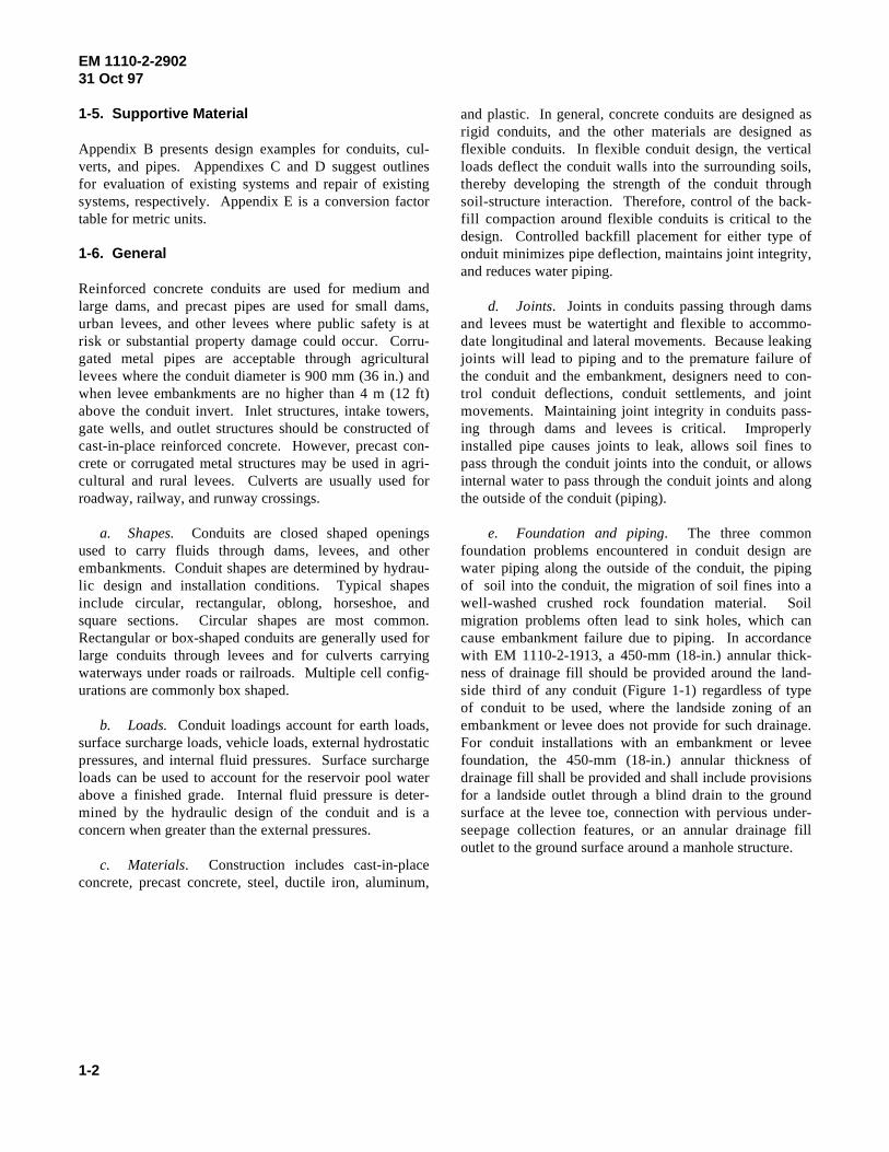
a. Shapes. Conduits are closed shaped openings e. Foundation and piping. The three commonused to carry fluids through dams, levees, and other foundation problems encountered in conduit design areembankments. Conduit shapes are determined by hydrau- water piping along the outside of the conduit, the pipinglic design and installation conditions. Typical shapes of soil into the conduit, the migration of soil fines into ainclude circular, rectangular, oblong, horseshoe, and well-washed crushed rock foundation material. Soilsquare sections. Circular shapes are most common. migration problems often lead to sink holes, which canRectangular or box-shaped conduits are generally used for cause embankment failure due to piping. In accordancelarge conduits through levees and for culverts carrying with EM 1110-2-1913, a 450-mm (18-in.) annular thick-waterways under roads or railroads. Multiple cell config- ness of drainage fill should be provided around the land-urations are commonly box shaped. side third of any conduit (Figure 1-1) regardless of type
b. Loads. Conduit loadings account for earth loads, embankment or levee does not provide for such drainage.surface surcharge loads, vehicle loads, external hydrostatic For conduit installations with an embankment or leveepressures, and internal fluid pressures. Surface surcharge foundation, the 450-mm (18-in.) annular thickness ofloads can be used to account for the reservoir pool water drainage fill shall be provided and shall include provisionsabove a finished grade. Internal fluid pressure is deter- for a landside outlet through a blind drain to the groundmined by the hydraulic design of the conduit and is a surface at the levee toe, connection with pervious under-concern when greater than the external pressures. seepage collection features, or an annular drainage fill
c. Materials. Construction includes cast-in-placeconcrete, precast concrete, steel, ductile iron, aluminum,
and plastic. In general, concrete conduits are designed asrigid conduits, and the other materials are designed as
design. Controlled backfill placement for either type ofonduit minimizes pipe deflection, maintains joint integrity,and reduces water piping.
of conduit to be used, where the landside zoning of an
outlet to the ground surface around a manhole structure.
EM 1110-2-290231 Oct 97
1-3
Figure 1-1. Drainage fill along conduit
Chapter 2 Cast-in-Place Conduits for Dams
2-1. General
The selection of the most economical conduit cross section must depend on the designer's judgment and the consideration of all design factors and site conditions for each application. For fills of moderate height, circular or rectangular openings will frequently be the most practicable because of the speed and economy obtainable in design and construction. For openings of less than about 5.6 m2 (60 ft2), a single rectangular box probably will be most economical for moderate fills up to about 18.3 m (60 ft). However, a rectangular conduit entrenched in rock to the top of the conduit may be economical for higher fills since the applied vertical load need be only the weight of the earth directly above with no increase for differential fill settlement. The ratio of height to width should be about 1.50 to accommodate the range of loading conditions economically. Where there is a battery of outlet gates, a multiple-box shape is sometimes economical where acceptable from a hydraulic standpoint.
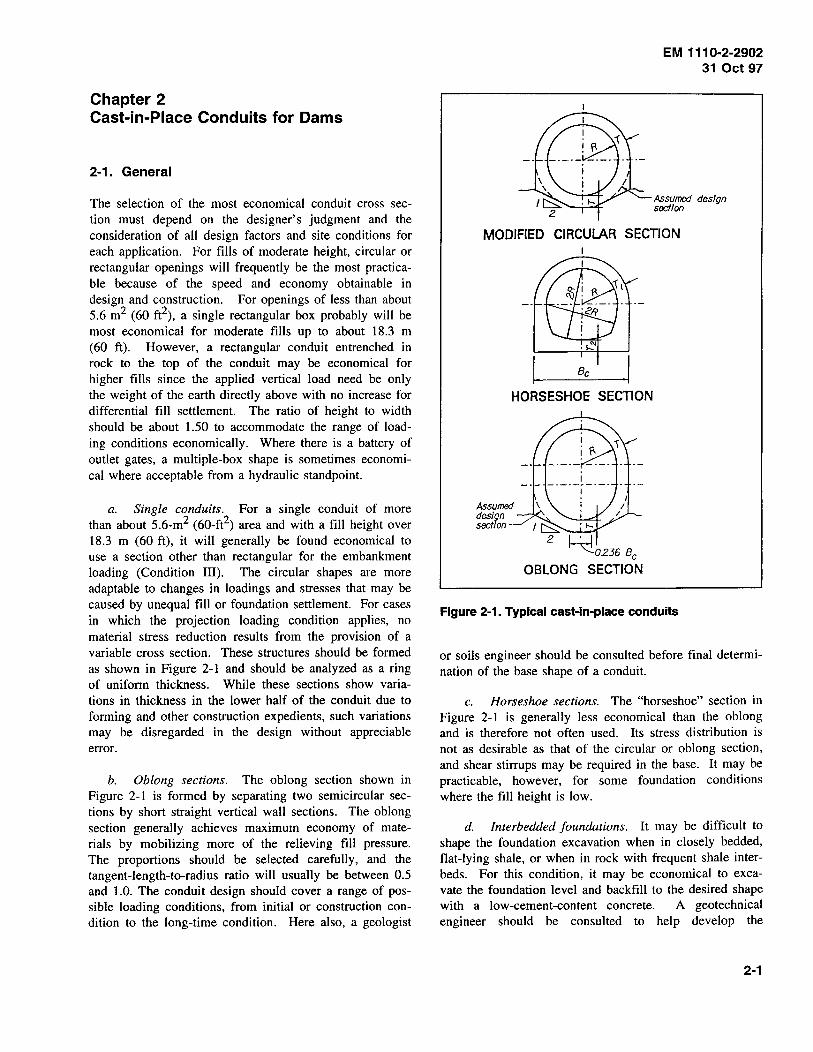
a. Single conduits. For a single conduit of more than about 5.6-m2 (60-ft2) area and with a fill height over 18.3 m (60ft), it will generally be found economical to use a section other than rectangular for the embankment loading (Condition III). The circular shapes are more adaptable to changes in loadings and stresses that may be caused by unequal fill or foundation settlement. For cases in which the projection loading condition applies, no material stress reduction results from the provision of a variable cross section. These structures should be formed as shown in Figure 2-1 and should be analyzed as a ring of uniform thickness. While these sections show variations in thickness in the lower half of the conduit due to forming and other construction expedients, such variations may be disregarded in the design without appreciable error.
b. Oblong sections. The oblong section shown in Figure 2-1 is formed by separating two semicircular sections by short straight vertical wall sections. The oblong section generally achieves maximum economy of materials by mobilizing more of the relieving fill pressure. The proportions should be selected carefully, and the tangent-length-to-radius ratio will usually be between 0.5 and 1.0. The conduit design should cover a range of possible loading conditions, from initial or construction condition to the long-time condition. Here also, a geologist
EM 1110-2-2902 31 Oct 97
Assumed desfqn section
MODIFIED CIRCULAR SECTION
Be
HORSESHOE SECTION
~0236 Be
OBLONG SECTION
Figure 2-1. Typical cast-in-place conduits
or soils engineer should be consulted before final determination of the base shape of a conduit.
c. Horseshoe sections. The "horseshoe" section in Figure 2-1 is generally less economical than the oblong and is therefore not often used. Its stress distribution is not as desirable as that of the circular or oblong section, and shear stirrups may be required in the base. It may be practicable, however, for some foundation conditions where the fill height is low.
d. Interbedded foundations. It may be difficult to shape the foundation excavation when in closely bedded, flat-lying shale, or when in rock with frequent shale interbeds. For this condition, it may be economical to excavate the foundation level and backfill to the desired shape with a low-cement-content concrete. A geotechnical engineer should be consulted to help develop the
2-1
EM 1110-2-2902 31 Oct 97
excavation plan. Excavation drawings should show the pay excavation lines and not the actual excavation lines. For a conduit under a dam, the designer should show the actual excavation lines rather than the pay excavation lines and the contractor should limit excavation to the actual excavation lines.
2-2. Materials
a. Concrete. Minimum compressive strength 28 MPa (4,000 psi) air entrained.
b. Reinforcement. Minimum yield strength, Grade 400 MPa (60,000 psi).
2-3. Installation
Conduits through dams are cast directly against the soil or rock and, therefore, bedding is not a design consideration. When overexcavation of the foundation materials is required, concrete fill should be used to maintain proper conduit grade. All foundation materials for cast-in-place conduits should be reviewed by a geotechnical engineer.
2-4. Loadings
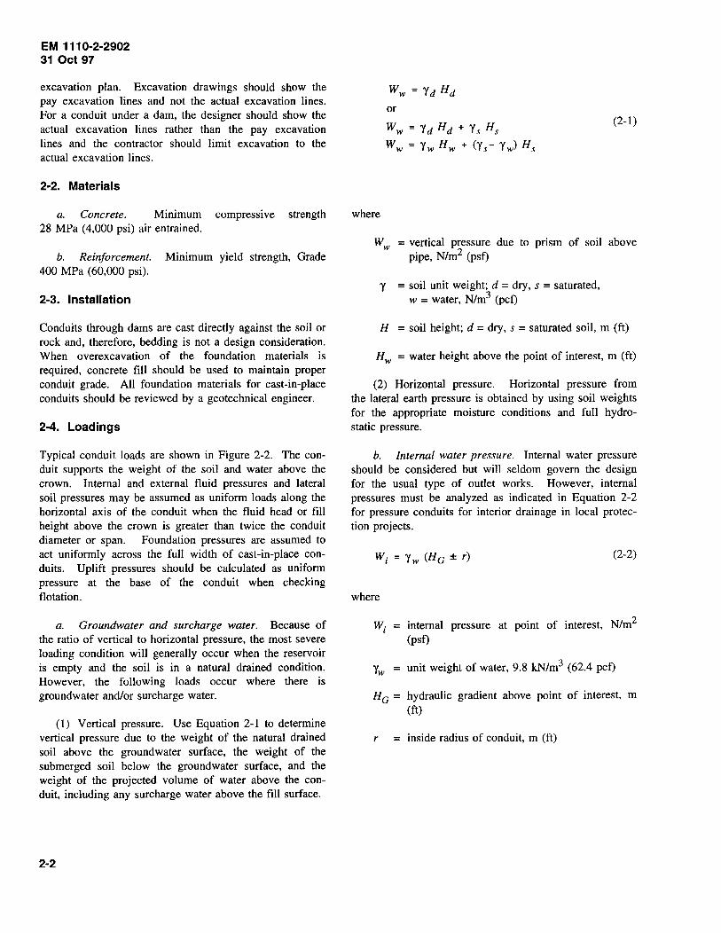
Typical conduit loads are shown in Figure 2-2. The conduit supports the weight of the soil and water above the crown. Internal and external fluid pressures and lateral soil pressures may be assumed as uniform loads along the horizontal axis of the conduit when the fluid head or fill height above the crown is greater than twice the conduit diameter or span. Foundation pressures are assumed to act uniformly across the full width of cast-in-place conduits. Uplift pressures should be calculated as uniform pressure at the base of the conduit when checking flotation.
a. Groundwater and surcharge water. Because of the ratio of vertical to horizontal pressure, the most severe loading condition will generally occur when the reservoir is empty and the soil is in a natural drained condition. However, the following loads occur where there is groundwater and/or surcharge water.
(1) Vertical pressure. Use Equation 2-1 to determine vertical pressure due to the weight of the natural drained soil above the groundwater surface, the weight of the submerged soil below the groundwater surface, and the weight of the projected volume of water above the conduit, including any surcharge water above the fill surface.
2-2
ww = Yd Hd
or
ww = Y d Hd + Ys Hs (2-1)
ww = Yw Hw + (Ys- Yw) Hs
where
W w = vertical pressure due to prism of soil above pipe, N/m2 (psf)
y = soil unit weight; d = dry, s = saturated, w = water, N/m3 (pcf)
H = soil height; d =dry, s = saturated soil, m (ft)
Hw = water height above the point of interest, m (ft)
(2) Horizontal pressure. Horizontal pressure from the lateral earth pressure is obtained by using soil weights for the appropriate moisture conditions and full hydrostatic pressure.
b. Internal water pressure. Internal water pressure should be considered but will seldom govern the design for the usual type of outlet works. However, internal pressures must be analyzed as indicated in Equation 2-2 for pressure conduits for interior drainage in local protection projects.
(2-2)
where
Wi = internal pressure at point of interest, N/m2
(psf)
Yw = unit weight of water, 9.8 kN/m3 (62.4 pcf)
HG = hydraulic gradient above point of interest, m (ft)
r = inside radius of conduit, m (ft)
Trench cond!tlon
Reservoir condition
EM 1110-2-2902 31 Oct 97
INTERNAL PRESSURE
------ When the height of fill Is greater than twice the trench width use the overage horizontal pressure computed at the pipe centerline
Figure 2-2. Typical conduit loadings
c. Concentrated live loads.
(1) Vertical pressure. Because soil conditions vary, designers can expect only a reasonable approximation when computing vertical pressures resulting from concentrated surface loads. The Boussinesq method is commonly used to convert surface point loads to vertical stress fields through the geometric relationship shown in Equation 2-3. This equation may be used for all types of soil masses including normally consolidated, overconsolidated, anisotropic, and layered soils. Stresses calculated by using this method are in close agreement with measured stress fields, and examples for using Equation 2-3 are shown in Figure 2-3.
(2-3)
where
We = vertical pressure due to concentrated load, N/m2 (psf)
P = concentrated load, N (lb)
z = depth to pressure surface, m (ft)
R = radial distance to pressure surface, m (ft)
(2) Horizontal pressure. Lateral loads caused by vehicles can be safely ignored due to their transient nature. However, a minimum lateral pressure of 0.005 of the wheel load for vehicles to a depth of 2.4 m (8 ft) should be considered in accordance with American Society for Testing and Materials (ASTM) C 857. For stationary surcharge loads, a lateral pressure can be calculated by using a Boussinesq equation such as Equation 2-4.
2-3

EM 1110-2-2902 31 Oct 97
------------~----
Given: P=44.5 kN (/0,000 lbs.J z=0.92 m (J ftJ r=0.61 m (2 ftJ
R· -J r2+z2
b-0.52 m (/.7 ftJ radius of a circular area
METHOD
BOUSSINEO
SQUARE AREA
CIRCULAR
LOAD PLANE PRESSURE FORMULA AT POINT CENTER
Kpo (psf! Kpo (psfJ
3Pz3
We • 2TTzR5 103 (215! 25J(525J
FIGURE 2-5 105 (220) 18.4 (384!
FIGURE 2-6 105 (220J 18.3 (383) 17.8 (372)
Wc.[/.0- I J
L·8·0.92 m (J ft) dimension of a square area t---------+---------1-----1---~ Wo [!+(b/zfft'Z
p
L=Lonq side of rectangular area 13J(275J 13J (275J
SIMPLIFIED ~2 w. •
fB+zXL+zJ e
p We • ra +zJ2
MINIMUM LATERAL PRESSURES
0.4 We (AREAJ (CQEJ
AASHTO :?J2 I.
Pyramid (2 ftJ minimum cCNer
172 (.359) 172 (359)
Pe Pe = 0.5 or !.ONe
Figure 2-3. Typical live load stress distribution
_ P [3zr2
Pc- ----21t R5
where
- (1 - 2~) l R(R + z)
(2-4)
Pc horizontal pressure from concentrated load, N/m2 (psf)
r = surface radius from point load P, m (ft)
R = radial distance to point in question, m (ft)
J.l = Poisson's ratio, 0.5 for saturated cohesive soils or 0.2 to 0.3 for other soils
Consult a geotechnical engineer for lateral loads from other surcharge conditions.
(3) Wheel loads. For relatively high fills, Equation 2-3 will give reasonably accurate results for highway and railroad wheel loads and the loads on relatively small footings. However, where the conduit is near the surface or where the contact area of the applied load is large,
2-4
these loads must be divided into units for a more accurate analysis. The use of influence charts as developed by Newmark (1942) will be helpful in computing the stress due to loads on relatively large and irregular areas.
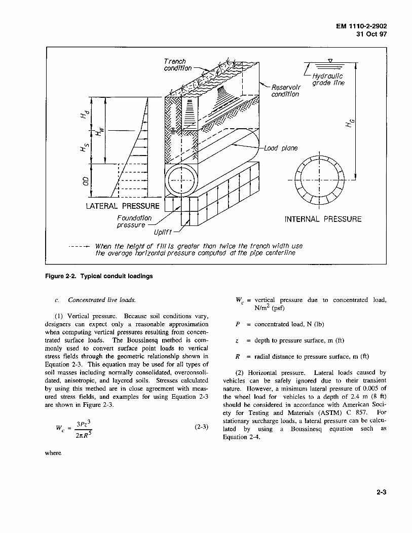
d. Backfill. The behavior of the soil pressures transmitted to a conduit or culvert by the overlying fill material is influenced by the physical characteristics and degree of compaction of the soil above and adjacent to the conduit or culvert as well as the degree of flexibility and the amount of settlement of the conduit or culvert. The effect of submergence in the backfill must also be considered as indicated in Figure 2-2. Direct measurements of such pressures have been made for smalldiameter pipes under relatively low fills. Until more data are available, the following loading should be used for rigid conduits and culverts for dams and levees and outlet conduits for interior drainage. The effect of submergence in the backfill must be considered. The three typical conduit installation conditions are trench, trench with superimposed fill, and embankment. Terms for these loading conditions are defined in Figure 2-4.
EM 1110-2-2902 31 Oct 97
He ·10 500mm (35 ftJ Inside Diameter • 1200mm (4'-()"J bd • 2100mm (7'-(lJ ¥' •173 kN/m3mo pcfJ Ordinary Clay Class B Bedding DLOAD • 289 kN/m 0.984 plf)
TRENCH (CONDITION I)
He • 10 500mm (35 ff) Inside Diameter "1200mm (4'-()"J bd • 2/00mm {7'-(!J 6 - 17 3 kN/m3 mo pcf) p' ·1.0 Class B Bedding DLOAD • 333 kN/m (2,287 p/f)
TRENCH WITH SUPERIMPOSED FILL (CONDITION ll )
Natural Ground
He • 10 500mm (35 ftJ Inside Diameter • 1200mm (4'-()"J Y ·17 J kN/m3 mo pcfJ Ordinary Sol/ p. 07 Class B Bedding DLONJ z 433 kN/m (2,970 pff)
EMBANKMENT (CONDITION ill)
Figure 2-4. Loading conditions for conduits
2-5

EM 111 0-2-2902 31 Oct 97
(1) Trench with no superimposed fill (Condition I).
(a) Loads from the trench backfill condition are applied to those structures that are completely buried in a trench with no superimposed fill above the top of the trench. To satisfy this condition, the width of the trench measured at the top of the conduit should be no greater than one and one-half times the overall width of the conduit, and the sides of the ditch above the top of the conduit should have a slope no flatter than one horizontal to two vertical. The total dead load of the earth at the top of the conduit should be computed as the larger of the two values obtained from Equations 2-5 through 2-7.
(2-5)
or
(2-6)
(2-7)
where
We = total dead load of earth at top of conduit, N/m (lbf/ft)
cd = trench coefficient, dimensionless
Bd = trench width at top of conduit< 1.5 be, m (ft)
Be = outside diameter of conduit, m (ft)
H = variable height of fill, m (ft). When He ~ 2Bd, H = Hh. When He < 2Bd, H varies over the height of the conduit.
p' = soil constant, dimensionless
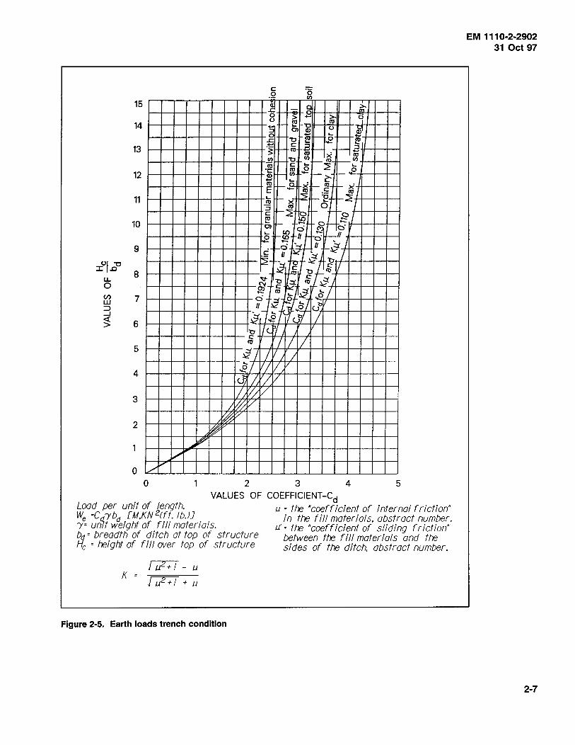
Values for Kp' and Cd can be taken from Figure 2-5.
(b) When the height of the fill above the top of the conduit (He) is less than twice the trench width, the horizontal pressure should be assumed to vary over the height of the conduit. When He is equal to or greater than 2sd• the horizontal pressure may be computed at the center of the conduit using an average value of H equal to Hh
2-6
applied uniformly over the height of the conduit. When He < 2Bd, the horizontal pressure in N/m2 (psf) at any depth should be computed using Equation 2-8.
where
p e = horizontal earth pressure, N/m2 (psf)
y = unit weight of fill, N/m3 (pcf)
<I> = angle of internal friction of the fill material, degrees
Ka = active pressure coefficient, N (lb)
(c) In most cases, the unit weight and the internal friction angle of the proposed backfill material in dry, natural drained, and submerged conditions should be determined by the laboratory and adapted to the design. However, where economic conditions do not justify the cost of extensive investigations by a soils laboratory, appropriate values of unit weight of the material and its internal friction angle should be determined by consultation with the soils engineer.
(d) Where submergence and water surcharge are applicable, the loadings must be modified. To obtain the total vertical load, the weight of the projected volume of water above the conduit, including any surcharge water above the fill surface, is added to the larger value of we obtained by using the submerged weight of the material used in Equations 2-5 and 2-6. The horizontal pressure i~ obtained by adding the full hydrostatic pressure to the pressure found by Equation 2-8 using the submerged weight of material.
(2) Trench with superimposed fill (Condition II).
(a) This loading condition applies to conduits that are completely buried in a trench with a superimposed fill H1 above the top of the trench. The trench width and side sfopes have the same lim\tations as specified for the trench condition. The vertical and horizontal unit loads for this loading condition vary between the computed values for the Conditions I and III (trench and embankment conditions) in proportion to the ratio Hj(He + HP). The vertical load, in N/m (pounds per foot) of conduit length, for the Condition II (trench with superimposed fill) should be computed as the larger of the two values obtained from Equations 2-9 and 2-10.
15
14
13
12
11
10
9
01 "'C :::Z::.£:1 8 u.
0 U) 7 w :::1 ...J
~ 6
5
4
c 0 ·o
rn
~ ~--~ g ~ 0 > .... >- <-: 0 10 10
"<;: 1- C5l -"i 0 ~ .s ~ .._ ~ .r. 1- "'C (lJ 1-- 0 1- 10 .... '+- ""
-~ 1- ~ .a I- f- E m x 10
rn I- -c rn I- 10 _ rn 10 c .... ::2 L..
-~ Hm_ .!2 t-- ~ .2 .... .... ~ I 10 §" 10. E f-- ~ f- .!: - lti I l'i; 1- X ~f-"E 1-~~
- (lJ 0 ~ I- ::2 0 1- f-0./ ~~-- ~ 0 ::::: O> • .rl o·
10 0 -o 1-<a II o· II
"": cd r:J U ~Jt f c , ~ . I
;:{-o::t.~~ ~-1! "tit
o)-1C I ~ IO~i/-~ . f -fltfjf (Jb ~ .2 <-b I
"0 1/<.. PI c I I I 10
~I I I I ~I llj 1/ v <] /, II v / V/ v
3 ;k0 v 2 ~ t;/
~ ~ ltP
v 0
v /
0 2 3 4 5
Load per unit of length. We =Cd.!'bd [M,KN 2rft. lb.JJ
VALUES OF COEFFICIENT-Cd
')'= untf weight of fill materials. bd= breadth of ditch at top of structure He = height of fill over top of structure
K
Figure 2-5. Earth loads trench condition
1.1 =the ·coefficient of internal friction" in the fill materials. abstract number.
1.1' ~the "coefficient of sliding friction" between the fill materials and the sides of the ditch. abstract number.
EM 1110-2-2902 31 Oct 97
2-7
EM 1110-2-2902 31 Oct 97
(2-9)
or
(2-10)
where
y = unit weight of fill, N/m3 (pcf)
bd = trench width, m (ft), bd :5: = 1.5 be
Hf = height of superimposed fill above the top of the trench, m (ft)
He = height of fill above top of conduit, m (ft)
HP = height of conduit above level adjacent foundation, m (ft)
be = outside dimension of conduit, m (ft)
H h = height of fill above horizontal diameter of conduit, m (ft)
(b) For low fills it may be desirable to use an effective height slightly less than Hh. The horizontal pressure for Condition II loading IS determined using Equation 2-11.
P, = yH tan2 (·s· -i} [H"~!HP l (2-11)
[o.5 yH - yH tan2 (45· - ; ]
where
2-8
H = variable height of fill above conduit, m (ft) (see definition, paragraph 2-4d(l)(a))
(c) For loading cases with submergence and water surcharge, the horizontal and vertical earth pressures should be similarly proportioned between the results obtained for Conditions I and III (trench and embankment conditions) with surcharge added to the hydrostatic pressure.
(3) Embankments (Condition III).
(a) Condition III applies to conduits and culverts that project above an embankment subgrade and to conduits and culverts in ditches that do not satisfy the requirements of Condition I or II. For this condition, the design should cover a range of possible loading conditions from the initial condition to the long-time condition by satisfying two extreme cases: Case 1, with pJWe = 0.33 (We = 150 percent vertical projected weight of fill material, lateral earth pressure coefficient k = 0.50); and Case 2, pJWe = 1.00 (We = 100 percent vertical projected weight of fill material, k = 1.00). The total vertical load in N/m (lbf/ft) for this condition should be computed as shown in Equations 2-12 and 2-13:
For Case 1, We = 1.5 "(ofth (2-12)
For Case 2, We = "(ofth (2-13)
or the unit vertical load N/m2 (psf), We, as given by Equations 2-14 and 2-15:
For Case 1, We= 1.5 y Hh (2-14)
For Case 2, We = y Hh (2-15)
The horizontal loading N/m2 (psf) should be taken as shown in Equations 2-16 and 2-17:
For Case 1, Pe = 0.5 y H (2-16)
For Case 2, Pe = y H (2-17)
Normal allowable working stresses should apply for both Case 1 and Case 2.
(b) Where submergence and water surcharge are applicable, their effects must be considered as for Condition I. In such cases, the vertical load as computed by Equations 2-12 through 2-17, using the submerged weight of the material should be increased by the weight of the projected volume of water above the conduit including any surcharge water above the fill surface. When a clay
blanket is applied to the face of the darn, the weight of water above the blanket must be included but the soil weight below the blanket and above the phreatic line (or the line of saturation where capillarity exists) is that for the natural drained condition. The horizontal unit pressure is found by adding full hydrostatic pressure to the value of p, obtained from Equation 2-16 or 2-17 using the submerged weight of the material.
2-5. Special Conditions
a. General. If conditions are encountered that warrant deviation from the loading criteria discussed above, justification for the change should be submitted with the analysis of design. However, the designer must first select the most economical method of installation. Where the rock surface occurs above the elevation of the bottom of the conduit, the designer should investigate the relative costs of excavating away from the conduit and backfilling between the conduit and the excavation line, allowing sufficient space between the conduit and the excavation line for operation of compaction rollers, and placing the conduit directly against rock as indicated for the following conditions.
b. Walls cast against rock. Where the conduit walls are placed directly against rock and the rock surface is at or above the top of the crown, the soil weight should be taken as 1.0 times the weight of material above, rather than 1.5, and the lateral pressure should be hydrostatic only, where applicable. Where the rock surface is at an intermediate level between crown and invert, use judgment to select a value between 1.0 and 1.5 to multiply by the weight of material above to obtain the correct soil design load. Lateral soil pressure should be applied only above the rock level and hydrostatic pressure as applicable over the full height of conduit. For either of these cases, the condition with no hydrostatic pressure should also be considered.
2-6. Methods of Analysis
Cast-in-place conduits can be designed using simplified elastic analysis or with finite element codes. Specialized finite element codes are available that feature nonlinear soil elements. These specialized codes provide the most accurate analysis. If these codes are not available, general finite element codes can be used, but they may need to be calibrated to the actual soil conditions. The finite element approach lends itself to parametric studies for rapid analysis of various foundation, bedding, and compaction conditions. Consult a geotechnical engineer for determination of soil spring constants to be used in the finite
EM 1110-2-2902 31 Oct 97
element model. Both concrete thickness and reinforcing steel area should be varied to obtain the best overall economy.
a. Finite element analysis. Finite element analysis is a useful method to design sections with unique shape for various field stresses. This method can be used to approximate the soil-structure interaction using spring foundations and friction between elements. These models calculate flexure and shear loads on the design section directly from soil-structure interaction relationships. The design of reinforcement for flexure and shear should be in accordance with EM 1110-2-2104. When the inside face steel is in tension, the area of steel needs to be limited to reduce the effects of radial tension. Therefore, limits on the amount of inside face steel that can be developed are necessary to prevent interior face concrete spalls or "slabbing failures." If more steel is required to develop the flexural capacity of the section, use radial ties. They should be designed in accordance with American Concrete Institute (ACI) 318 for shear reinforcement.
b. Curvilinear conduits and culverts (CURCON). This Computer-Aided Structural Engineering (CASE) program performs a structural analysis for conduit shapes including horseshoe, arch, modified oblong, and oblong sections with constant thickness, base fillets, or a square base. Loads that can be analyzed include groundwater and surcharge water in embankment backfills.
2-7. Reinforcement
a. Minimum longitudinal. Longitudinal reinforcement should be placed in both faces of the conduit as shown in Figure 2-6. The minimum required area of reinforcement should not be less than 0.0028 times the gross area of concrete, half in each face, with a maximum of #30M at 300 mm (#9 at 12 in.) in each face. Generally, the same reinforcement will be in each face. Maximum spacing of bars should not exceed 450 mm (18 in).
b. Minimum transverse. Minimum transverse reinforcement should be placed in both inside and outside faces. Minimum required area of transverse steel, even when not carrying computed stresses, should not be less than 0.002 times the nominal area of concrete in each face, but not more than #25M at 300 mm (#8 at 12 in.) in each face, unless required to carry the computed stresses. Compression reinforcement in excess of this minimum should not be used.
2-9

EM 111 0-2-2902 31 Oct 97
Notes:
-------------------LS----------------~
{of Dam '
UPSTREAM I
'-""-LS/3-DOWNSTREAM
For monolith lengths see paragraph 2-8 of text
LRelnforced concrete
RESERVOIR OUTLET WORKS-LONGITUDINAL SECTION THROUGH CONDUIT ON ROCK
I. Conduit strength sfl>uld vary roughly In accordance with height of overburden or other loading conditions so the overall structure w/11 have essentially a constant safety factor throughout Its len<;th. Prefabricated conduit can usually be varied for strength class commercially available. For cast-m-place conduit both concrete thickness and reinforcing steel area stoold be varied to obtain the best overall econom;. · 2.. The •corps EM 1110-2-2102.. Waterstops and other Joint Materials", !1/ustrotes various shapes of rubber and polyvln;lchlorlde commercially available.
IOOmm (4'1 clear. typ
Top form inner surface above point of 0.75: /J slope
Where severe erosion Is anticipated the protective covering should gradually Increase to about 150mm (6'1 at the Invert
Symm.~ about c_ 1
..
..
Flexible waterstop r not 2J see e ']
A .. . ---:--. - - -
. A
I '
I A •
• . TOP •
- - - r-
.. . BOTIOM .
,\_ Monolith joint
OBLONG SECTION
MODIFIED CIRCULAR SECTION
DETAIL SHOWING CONTRACTION JOINTS
Figure 2-6. Typical conduit details (large dams)
2-10
c. Minimum cover. Minimum concrete cover of reinforcement should not be less than 100 mm (4 in.).
2-8. Joints
a. Transverse monolith joints. Maximum contraction joint spacing should not exceed 6 m (20 ft) on earth foundations and 9 m (30 ft) on rock, as shown in Figure 2-6. When large settlements are expected, these maximum spacings should be reduced to allow for more movement in the joint. A geotechnical engineer should be consulted for soil settlements.
b. Longitudinal construction joints. The position of the longitudinal construction joints indicated in Figure 2-6 can be varied to suit the construction methods used. When circular and oblong conduits are used, the concrete in the invert section should be top-formed above the point where the tangent to the invert is steeper than 1 vertical on 1.75 horizontal.
2-9. Waterstops
EM 1110-2-2902 31 Oct 97
Flexible-type waterstops should be used in all transverse contraction joints, as shown in Figure 2-6. Guidance on the selection of waterstop materials is given in EM 1110-2-2102. Where large differential movement is expected, a center-bulb-type waterstop and a joint separation of approximately 13 mm (112 in.) should be used. When the conduit rests on a rather firm foundation, a two-bulb or equivalent type waterstop should be used with a joint separation of approximately 6 mm (1/4 in.). For conduit on rock foundations with little expected deformation, the joint should be coated with two coats of mastic and an appropriate waterstop should be used.
2-10. Camber
When conduits are cast-in-place, large settlements are usually not a major concern. However, where considerable foundation settlements are likely to occur, camber should be employed to ensure positive drainage.
2-11
Chapter 3 Circular Reinforced Concrete Pipe for Small Dams and Levees
3-1. General
Reinforced concrete pipe should be used for small dams, urban levees, and other levees where loss of life or substantial property damage could occur. Reinforced concrete pipe may also be used for less critical levees. Ancillary structures such as inlet structures, intake towers, gate wells, and outlet structures should be constructed with cast-in-place reinforced concrete. However, precast concrete may be used for less critical levees when designed and detailed to satisfy all loading and functional requirements.
3-2. Materials: Small Dams
a. Overview. Reinforced concrete pipe discussed in this chapter is designed by either the direct or indirect (D-load) method. This approach indirectly compares the moments and shears for the pipe section to a standard three-edge bearing test. The minimum diameter pipe used should be 1,220 mm (48 in.) to facilitate installation, maintenance, and inspection.
b. Reinforced concrete pipe through dams. Pipe through small dams should be concrete pressure pipe, steel cylinder type. Pipe joints should be deep or extra deep with steel joint rings and solid 0-ring gaskets, and they should be used for the entire length of pipe between the intake structure and the stilling basin. The steel cylinder provides longitudinal reinforcement and bridges the gap if transverse cracks develop in the concrete. Steel joint rings can be readily attached to the steel cylinder. Reinforced concrete pipe with either steel end rings or a concrete bell-and-spigot joint can be used in less critical areas. Joints should have solid 0-ring gaskets, and the pipe may or may not be prestressed. Also, a steel cylinder is optional. All acceptable pipe must be hydrostatic tested.
(1) Steel cylinder. When the steel cylinder is used, the cylinder should have a minimum thickness of 1.5 mm (0.0598 in.) and 25 mm (1 in.) minimum concrete cover.
(2) Prestress wire. When prestressing is used, the wire should have a minimum diameter of 5 mm (0.192 in).
EM 111 0-2-2902 31 Oct 97
(3) Mortar covering. The minimum concrete cover over prestressing wire should be 19 mm (3/4 in.).
( 4) Concrete cover. The minimum concrete cover over plain reinforcing bars or welded wire fabric should be 38 mm (1.5 in).
(5) Cement. Cement used for concrete, grout, or mortar shall be type II.
(6) Steel skirts. These skirts are used on prestressed noncylinder concrete pipe to hold the steel ring in place. Skirts shall be welded to steel joint rings for noncylinder pipe, and longitudinal reinforcement shall be welded to the steel skirt for anchorage.
(7) Reinforced concrete pressure pipe, steel cylinder type. Design in accordance with American Water Works Association (A WW A) C 300. This pipe is designed by the direct method in accordance with A WW A C304.
(8) Prestressed concrete pressure pipe, steel cylinder type. Design pressure pipe in accordance with A WW A C 301. This pipe is designed by the direct method in accordance with A WW A C 304.
(9) Reinforced concrete pressure pipe. Design in accordance with A WW A C 302 or ASTM C 76. This pipe is designed by the indirect method (D-load).
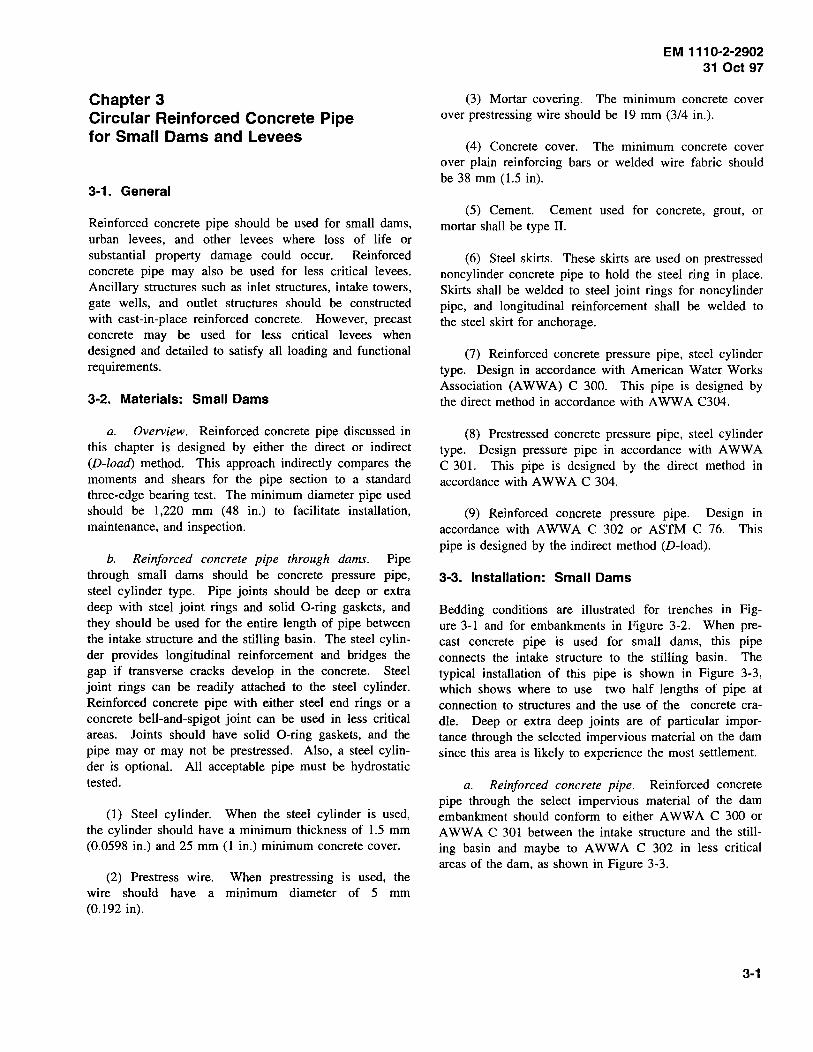
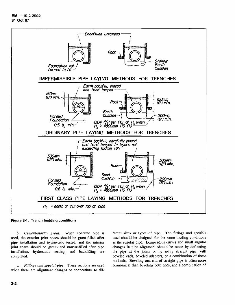
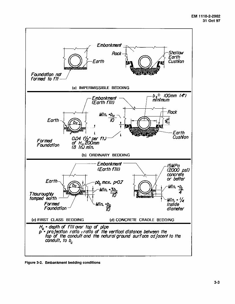
3-3. Installation: Small Dams
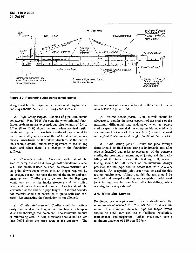
Bedding conditions are illustrated for trenches in Figure 3-1 and for embankments in Figure 3-2. When precast concrete pipe is used for small dams, this pipe connects the intake structure to the stilling basin. The typical installation of this pipe is shown in Figure 3-3, which shows where to use two half lengths of pipe at connection to structures and the use of the concrete cradle. Deep or extra deep joints are of particular importance through the selected impervious material on the dam since this area is likely to experience the most settlement.
a. Reinforced concrete pipe. Reinforced concrete pipe through the select impervious material of the dam embankment should conform to either A WW A C 300 or A WW A C 301 between the intake structure and the stilling basin and maybe to A WW A C 302 in less critical areas of the dam, as shown in Figure 3-3.
3-1
EM 111 0-2-2902 31 Oct 97
Foundation not j formed to fit
Rock
Slr:JIIow Earth Cuslion
IMPERMISSIBLE PIPE LAYING METHODS FOR TRENCHES
150mm f6"J min.
Formed Foundation
0.5 be min.
Earth backf111, placed and lr:Jnd tamped------...
ORDINARY PIPE
300mm (J2"J min.
Earth backfiJJ, carefully placed and lr:Jnd tamped In layers not exceeding 150mm (6")
Rockl a Sand ~==::\----+ Cuslion --L_S.·:.::·:.::.:></ :::.: .. !;,.:
OIJ4 t~· per ftJ of He when He > 48oi:Jmm (16 ftJ
150mm t6"J min.
200mm (8') min.
300mm (12") min.
200mm (fJ'J min.
FIRST CLASS PIPE LAYING METHODS FOR TRENCHES
He ·depth of fill CNer top of pipe
Figure 3-1. Trench bedding conditions
b. Cement-mortar grout. When concrete pipe is used, the exterior joint space should be grout-filled after pipe installation and hydrostatic tested, and the interior joint space should be grout- and mortar-filled after pipe installation, hydrostatic testing, and backfilling are completed.
c. Fittings and special pipe. These sections are used when there are alignment changes or connections to dif-
3-2
ferent sizes or types of pipe. The fittings and specials used should be designed for the same loading conditions as the regular pipe. Long-radius curves and small angular changes in pipe alignment should be made by deflecting the pipe at the joints or by using straight pipe with beveled ends, beveled adapters, or a combination of these methods. Beveling one end of straight pipe is often more economical than beveling both ends, and a combination of
Embankment ---+->-~"-------.J"---+
F oundatlon not formed to fit
Earth
Rock
Earth
(a) IMPERMISSIBLE BEDDING
Embankment lEarth fill)
Min. •be ~ 10 _L
___j_ ' r·~~~J
O.D4 (~ • :e, ftJ _/I Formed Foundation
Earth
. Ttourougtly tamped earth
Formed Foundation
of Hc200mm lB lnJ min.
(b) ORDINARY BEDDING
.-------Embankment --------. lEorth fill)
pbc max. p-07
/~H--'f-/ Min. •3bc 10
Shall ON Earth Cuslion
b~+ IOOmm l4J mtniiTI.Jm
15MPa (2000 psi) concrete or better
Min.·~ 4
Min.·~ Inside diameter
(c) FIRST CLASS BEDDING (d) CONCRETE CRADLE BEDDING
He· depth of fill wer top of pipe p ·projection ratio :ratio of tf'IJ vertical distance between tf'IJ
top of tf'IJ conduit and tf'IJ natural ground surf ace ad ]acent to tte conduit, to be
Figure 3-2. Embankment bedding conditions
EM 111 0-2-2902 31 Oct 97
3-3
EM 1110-2-2902 31 Oct 97
UPSTREAM
i of Small Dam I
DOWNSTREAM
Drainage Fill (see EM/1/G-2-19/3 and EM/110-2-2300 for more details)
Reinforced Concrete Pipe from inlet structure to toe of the embankment
Figure 3-3. Reservoir outlet works (small dams)
straight and beveled pipe can be economical. Again, steel end rings should be used for fittings and specials.
d. Pipe laying lengths. Lengths of pipe used should not exceed 4.9 m (16 ft) for conduits when minimal foundation settlements are expected, and pipe lengths of 2.4 to 3.7 m (8 to 12 ft) should be used when nominal settlements are expected. Two half lengths of pipe should be used immediately upstream of the intake structure, immediately downstream of the intake structure, at the end of the concrete cradle, immediately upstream of the stilling basin, and when there is a change in the foundation stiffness.
e. Concrete cradle. Concrete cradles should be used to carry the conduit through soft foundation materials. The cradle is used between the intake structure and the point downstream where it is no longer required by the design, but not less than the toe of the major embankment section. Cradles are to be used for the first pipe length upstream of the intake structure and the stilling basin and under horizontal curves. Cradles should be terminated at the end of a pipe length. Disturbed foundation material should be backfilled to grade with lean concrete. Recompacting the foundation is not allowed.
f Cradle reinforcement. Cradles should be continuously reinforced in the longitudinal direction with temperature and shrinkage reinforcement. The minimum amount of reinforcing steel in both directions should not be less than 0.002 times the gross area of the concrete. The
3-4
transverse area of concrete is based on the concrete thickness below the pipe invert.
g. Dowels across joints. Joint dowels should be adequate to transfer the shear capacity of the cradle or the maximum differential load anticipated when an excess cradle capacity is provided. A compressible material with a minimum thickness of 13 mm (112 in.) should be used in the joint to accommodate slight foundation deflections.
h. Field testing joints. Joints for pipe through dams should be field-tested using a hydrostatic test after pipe is installed and prior to placement of the concrete cradle, the grouting or mortaring of joints, and the backfilling of the trench above the bedding. Hydrostatic testing should be 120 percent of the maximum design pressure for the pipe and in accordance with A WW A standard. An acceptable joint tester may be used for this testing requirement. Joints that fail the test should be replaced and retested until they are acceptable. Additional joint testing may be completed after backfilling, when watertightness is questioned.
3-4. Materials: Levees
Reinforced concrete pipe used in levees should meet the requirements of A WW A C 302 or ASTM C 76 as a minimum. The minimum diameter pipe for major levees should be 1,220 mm (48 in.) to facilitate installation, maintenance, and inspection. Other levees may have a minimum diameter of 910 mm (36 in.).
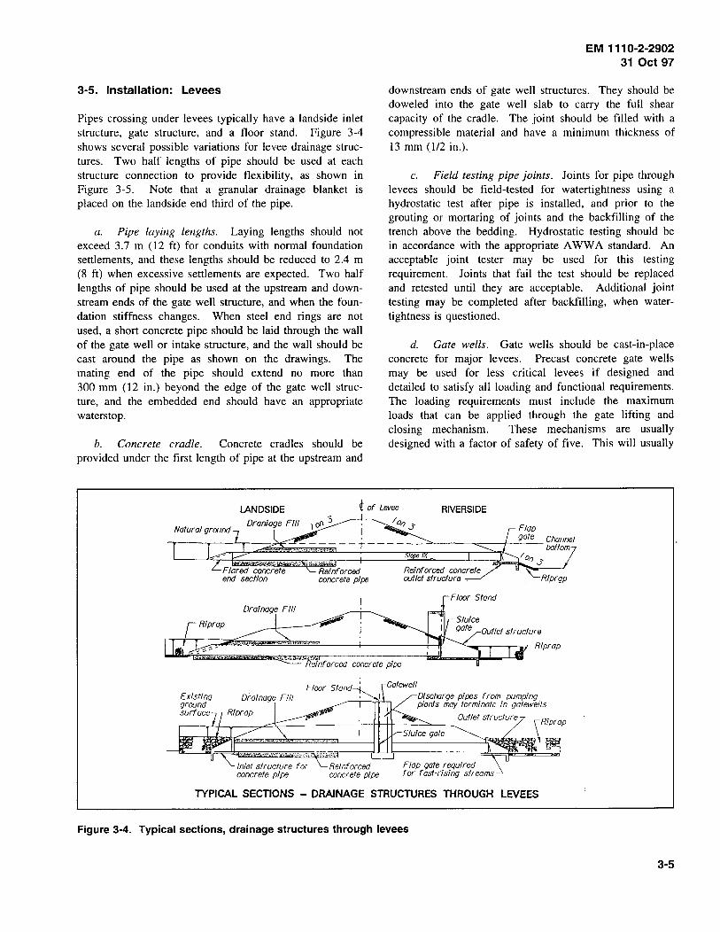
3-5. Installation: Levees
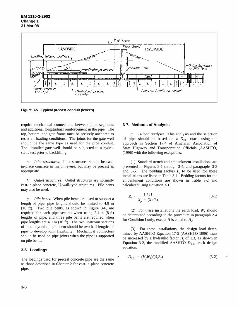
Pipes crossing under levees typically have a landside inlet structure, gate structure, and a floor stand. Figure 3-4 shows several possible variations for levee drainage structures. Two half lengths of pipe should be used at each structure connection to provide flexibility, as shown in Figure 3-5. Note that a granular drainage blanket is placed on the landside end third of the pipe.
a. Pipe laying lengths. Laying lengths should not exceed 3.7 m (12 ft) for conduits with normal foundation settlements, and these lengths should be reduced to 2.4 m (8 ft) when excessive settlements are expected. Two half lengths of pipe should be used at the upstream and downstream ends of the gate well structure, and when the foundation stiffness changes. When steel end rings are not used, a short concrete pipe should be laid through the wall of the gate well or intake structure, and the wall should be cast around the pipe as shown on the drawings. The mating end of the pipe should extend no more than 300 mm (12 in.) beyond the edge of the gate well structure, and the embedded end should have an appropriate waters top.
b. Concrete cradle. Concrete cradles should be provided under the first length of pipe at the upstream and
EM 1110-2-2902 31 Oct 97
downstream ends of gate well structures. They should be doweled into the gate well slab to carry the full shear capacity of the cradle. The joint should be filled with a compressible material and have a minimum thickness of 13 mm (112 in.).
c. Field testing pipe joints. Joints for pipe through levees should be field-tested for watertightness using a hydrostatic test after pipe is installed, and prior to the grouting or mortaring of joints and the backfilling of the trench above the bedding. Hydrostatic testing should be in accordance with the appropriate A WW A standard. An acceptable joint tester may be used for this testing requirement. Joints that fail the test should be replaced and retested until they are acceptable. Additional joint testing may be completed after backfilling, when watertightness is questioned.
d. Gate wells. Gate wells should be cast-in-place concrete for major levees. Precast concrete gate wells may be used for less critical levees if designed and detailed to satisfy all loading and functional requirements. The loading requirements must include the maximum loads that can be applied through the gate lifting and closing mechanism. These mechanisms are usually designed with a factor of safety of five. This will usually
LANDSIDE i of Levee RIVERSIDE
Drainage Fill
Inlet structure for concrete pipe
Reinforced concrete pipe
e nf arced concrete pipe
Reinforced concrete outlet structure ,
Rlprap
Dlscrorge pipes from pumping plants may terminate in qatewells
Flap gate required for fast-rlsinq streams
TYPICAL SECTIONS - DRAINAGE STRUCTURES THROUGH LEVEES
Figure 3-4. Typical sections, drainage structures through levees
3-5
� �
Bf 1.431
Xp (Xa/3)
D0.01 = (HfWT)/(Si Bf )
EM 1110-2-2902Change 131 Mar 98
3-6
Figure 3-5. Typical precast conduit (levees)
require mechanical connections between pipe segmentsand additional longitudinal reinforcement in the pipe. Thetop, bottom, and gate frame must be securely anchored toresist all loading conditions. The joints for the gate wellshould be the same type as used for the pipe conduit.The installed gate well should be subjected to a hydro-static test prior to backfilling.
e. Inlet structures. Inlet structures should be cast-in-place concrete in major levees, but may be precast asappropriate.
f. Outlet structures. Outlet structures are normallycast-in-place concrete, U-wall-type structures. Pile bentsmay also be used.
g. Pile bents. When pile bents are used to support alength of pipe, pipe lengths should be limited to 4.9 m(16 ft). Two pile bents, as shown in Figure 3-6, arerequired for each pipe section when using 2.4-m (8-ft)lengths of pipe, and three pile bents are required whenpipe lengths are 4.9 m (16 ft). The two upstream sectionsof pipe beyond the pile bent should be two half lengths ofpipe to develop joint flexibility. Mechanical connectorsshould be used on pipe joints when the pipe is supportedon pile bents.
3-6. Loadings
The loadings used for precast concrete pipe are the sameas those described in Chapter 2 for cast-in-place concretepipe.
3-7. Methods of Analysis
a. D-load analysis. This analysis and the selectionof pipe should be based on a D crack using the0.01
approach in Section 17.4 of American Association ofState Highway and Transportation Officials (AASHTO)(1996) with the following exceptions.
(1) Standard trench and embankment installations arepresented in Figures 3-1 through 3-4, and paragraphs 3-3and 3-5. The bedding factors B to be used for thesef
installations are listed in Table 3-1. Bedding factors for theembankment conditions are shown in Table 3-2 andcalculated using Equation 3-1:
(3-1)
(2) For these installations the earth load, W shouldE
be determined according to the procedure in paragraph 2-4for Condition I only, except H is equal to H .c
(3) For these installations, the design load deter-mined by AASHTO Equation 17-2 (AASHTO 1996) mustbe increased by a hydraulic factor H of 1.3, as shown inf
Equation 3-2, the modified AASHTO D crack design0.01
equation:
(3-2)

Treated bridge
II II Ll Ll
PROFILE NOT TO SCALE
beams ft x wJ, typ. 600 mm (2'-(J'J fTypJ
Treated timber I "t 'I pill()(} (d), typ.
,..---~~.._..· lvtomatic flap qate
/50mm (6"J
PIPE SUPPORT DETAILS NOT TO SCALE
AUTOMATIC FLAP GATE NOT TO SCALE
Figure 3-6. Typical pile bent
EM 1110-2-2902 31 Oct 97
Grouted ancmrs as required by flap qate manufacturer to fasten flap qate to reinforced concrete pipe
3-7

EM 111 0-2-2902 31 Oct 97
Table 3-1 Design Conditions: Trench
Type of Bedding Bedding Factor a,
Ordinary 1.5
First Class 1.9
Concrete Cradle 2.5
Table 3-2 Bedding Factor Constants: Embankment
Other Projection Projection Ratio Concrete Bedding Bedding p X a X a
0 0.15 0
0.3 0.743 0.217
0.5 0.856 0.423
0.7 0.811 0.594
0.9 0.678 0.655
1.0 0.638 0.638
Type of Bedding X
Ordinary 0.840
First Class 0.707
Concrete Cradle 0.505
where
and
3-8
H1 = hydraulic factor of 1.3
si = internal diameter or horizontal span of the pipe in mm (feet)
B1 = bedding factor. See Table 3-1 for trench condition and use Equation 3-1 with Table 3-2 for embankment condition
WE = earth load on the pipe as determined according to the procedures outlined in Chapter 2, using case 1 only except replacement of H with He
W F = fluid load in the pipe
WL = live load on the pipe as determined according to paragraph 5-4
b. Multiple pipes. When several pipes need to be installed in the same trench, the designer must determine the loading condition to use. Two common installation conditions are shown in Figures 3-7 and 3-8. The soil columns used for this loading analysis are identified in these figures. The design method described below provides conservative results.
z BcA r Bee r Bca z
COLUMNS OF BACKFILL ASSOCIATED WITH EACH PIPELINE
Figure 3-7. Multiple pipes in trench
COLUMNS OF BACKFILL ASSOCIATED WITH PIPEUNES IN A BENCHED TRENCH
Figure 3-8. Benched pipes
(1) Trench condition. Load for multiple pipes varies from a simple trench condition to a projected embankment
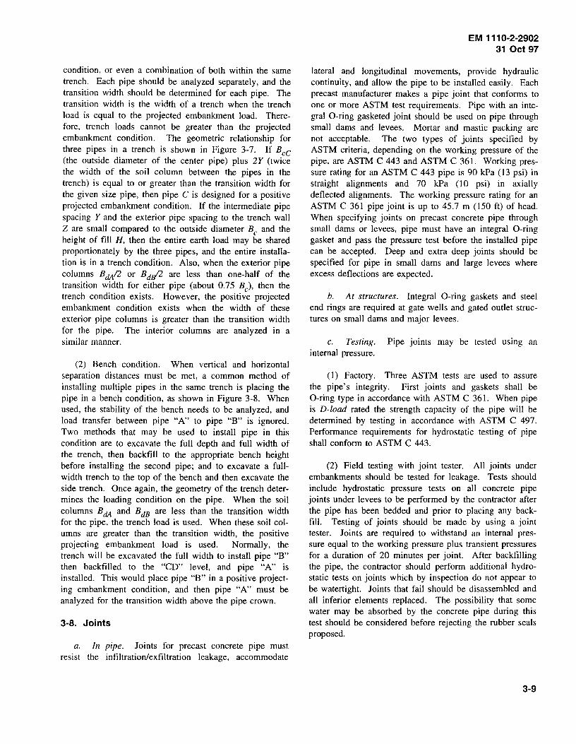
condition, or even a combination of both within the same trench. Each pipe should be analyzed separately, and the transition width should be determined for each pipe. The transition width is the width of a trench when the trench load is equal to the projected embankment load. Therefore, trench loads cannot be greater than the projected embankment condition. The geometric relationship for three pipes in a trench is shown in Figure 3-7. If Bee (the outside diameter of the center pipe) plus 2Y (twice the width of the soil column between the pipes in the trench) is equal to or greater than the transition width for the given size pipe, then pipe C is designed for a positive projected embankment condition. If the intermediate pipe spacing Y and the exterior pipe spacing to the trench wall Z are small compared to the outside diameter Be and the height of fill H, then the entire earth load may be shared proportionately by the three pipes, and the entire installation is in a trench condition. Also, when the exterior pipe columns BdA/2 or BdJ!2 are less than one-half of the transition width for either pipe (about 0.75 Be), then the trench condition exists. However, the positive projected embankment condition exists when the width of these exterior pipe columns is greater than the transition width for the pipe. The interior columns are analyzed in a similar manner.
(2) Bench condition. When vertical and horizontal separation distances must be met, a common method of installing multiple pipes in the same trench is placing the pipe in a bench condition, as shown in Figure 3-8. When used, the stability of the bench needs to be analyzed, and load transfer between pipe "A" to pipe "B" is ignored. Two methods that may be used to install pipe in this condition are to excavate the full depth and full width of the trench, then backfill to the appropriate bench height before installing the second pipe; and to excavate a fullwidth trench to the top of the bench and then excavate the side trench. Once again, the geometry of the trench determines the loading condition on the pipe. When the soil columns BdA and BdB are less than the transition width for the pipe, the trench load is used. When these soil columns are greater than the transition width, the positive projecting embankment load is used. Normally, the trench will be excavated the full width to install pipe "B" then backfilled to the "CD" level, and pipe "A" is installed. This would place pipe "B" in a positive projecting embankment condition, and then pipe "A" must be analyzed for the transition width above the pipe crown.
3-8. Joints
a. In pipe. Joints for precast concrete pipe must resist the infiltration/exfiltration leakage, accommodate
EM 1110-2-2902 31 Oct 97
lateral and longitudinal movements, provide hydraulic continuity, and allow the pipe to be installed easily. Each precast manufacturer makes a pipe joint that conforms to one or more ASTM test requirements. Pipe with an integral 0-ring gasketed joint should be used on pipe through small dams and levees. Mortar and mastic packing are not acceptable. The two types of joints specified by ASTM criteria, depending on the working pressure of the pipe, are ASTM C 443 and ASTM C 361. Working pressure rating for an ASTM C 443 pipe is 90 kPa (13 psi) in straight alignments and 70 kPa (10 psi) in axially deflected alignments. The working pressure rating for an ASTM C 361 pipe joint is up to 45.7 m (150 ft) of head. When specifying joints on precast concrete pipe through small dams or levees, pipe must have an integral 0-ring gasket and pass the pressure test before the installed pipe can be accepted. Deep and extra deep joints should be specified for pipe in small dams and large levees where excess deflections are expected.
b. At structures. Integral 0-ring gaskets and steel end rings are required at gate wells and gated outlet structures on small dams and major levees.
c. Testing. Pipe joints may be tested using an internal pressure.
(1) Factory. Three ASTM tests are used to assure the pipe's integrity. First joints and gaskets shall be 0-ring type in accordance with ASTM C 361. When pipe is D-load rated the strength capacity of the pipe will be determined by testing in accordance with ASTM C 497. Performance requirements for hydrostatic testing of pipe shall conform to ASTM C 443.
(2) Field testing with joint tester. All joints under embankments should be tested for leakage. Tests should include hydrostatic pressure tests on all concrete pipe joints under levees to be performed by the contractor after the pipe has been bedded and prior to placing any backfill. Testing of joints should be made by using a joint tester. Joints are required to withstand an internal pressure equal to the working pressure plus transient pressures for a duration of 20 minutes per joint. After backfilling the pipe, the contractor should perform additional hydrostatic tests on joints which by inspection do not appear to be watertight. Joints that fail should be disassembled and all inferior elements replaced. The possibility that some water may be absorbed by the concrete pipe during this test should be considered before rejecting the rubber seals proposed.
3-9

EM 1110-2-2902 31 Oct 97
(3) Water-filled pipe test. Where practical, pipe joints can be tested for watertightness in the field by using the water-filled pipe test. The pipe should be free of air during this test and be maintained at the test pressure for a minimum of 1 hour. The possibility that some water may be absorbed by the concrete pipes during this test should be considered before rejection of the rubber seals proposed. Water should be added as necessary to maintain a completely full pipe at the specified head. On outlet works pipe, testing can be in increments as installed or for the full length after installation is completed.
3-9. Camber
Where considerable foundation settlement is likely to occur, camber should be employed to assure positive drainage and to accommodate the extension of the pipe due to settlement, as shown in Figure 3-9 (EM 1110-2-1913).
3-10
£ I
Comber ollo.vs for settlement of a culvert under a figh fill. Most of the fall Is In the outlet mlf. Diameters 3000mm 110 ffJ and smaller ore easter to comber. as ore the 1/gtter wall tficknesses.
Figure 3-9. Cambered conduit
EM 1110-2-2902Change 131 Mar 98
4-1
* *
Chapter 4Corru gated Metal Pi pe for RuralLevees and Culverts
4-1. General
Corrugated metal pipe may be used in rural levee systemswhen risk of substantial property damage and loss of life islow. Corrugated metal pipe is subject to chemical andgalvanic corrosion, is not easily tapped, has a highhydraulic coefficient of friction, and is vulnerable to jointleakage and associated piping and to live load distortion.When this pipe is used, a life cycle cost analysis should beperformed. The service life of a flood control project is100 years, and corrugated metal pipe systems must bedesigned to meet this requirement. Typically, corrugatedmetal pipe may have to be replaced a minimum of onceduring this project life. Use 900-mm- (36-in.-) diameterpipe as a minimum for levees to facilitate installation,maintenance, and inspection.
a. Corrugated metal pipe. This pipe may be used asan option in agricultural levees where the levee embank-ment is less than 3.7 m (12 ft) above the pipe invert.Circular pipe must be used through levee embankments.
b. Corrosion protection. Corrugated metal pipe issusceptible to corrosion, primarily in the invert. The pipeshould always be galvanized and protected with a bitumi-nous coating and should have bituminous paving applied tothe invert. Bituminous coatings and paving can add about20 to 25 years of service life to the pipe, and a bituminouscoating (AASHTO M 190) alone adds about 8 years ofservice life to the pipe. Polymer coatings (AASHTO M246) can add about 10 years of service life to the pipe. Ifthe fill or backfill materials contain chemically activeelements, it may be necessary to protect the outside of thepipe with a coating of coal tar epoxy. The life of galva-nized conduits can be estimated by using information fromthe American Iron and Steel Institute's (AISI) Handbook ofSteel Drainage and Highway Construction Prod-ucts (1993). When considering other coatings, the designershould review applicable test data for similar installations.
(1) Metallic-coated corrugated steel pipe. Metallic-coated corrugated steel pipe should conform to AmericanAssociation of State Highway and Transportation Officials(AASHTO) M 36, M 218, M 246, and M 274. When spiralrib steel pipe is used, the material should conform toAASHTO M 36 and M 245. When bituminous coatings are
required, the material should conform to AASHTO M 190.For installations involving only fresh water, the Type Ccoating should be used except when the pH value of thesoil or the water at the installation site is below 5 orabove 9. In this case, the coating should be ASTM A 885,Aramid Fiber Composite, and AASHTO M 190. For allseawater installations, the coating should be ASTM A 885and AASHTO M 190. Both the loading conditions and thecorrosion characteristics (soil and water) at the installationsite should be considered when specifying metal thickness(steel). Metal thickness should be selected to meet thecorrosion condition and should not allow the pipe toperforate during the life of the project. The soil resistivityand pH can be determined by a geotechnical engineer. Thistype of pipe should not be used to conduct strong industrialwastes or raw sewage. In general the environmentalconditions for corrugated metal pipe require pH limits of 6to 8 for galvanized steel, and 5 to 9 for aluminized steel.Soil resistivity should be greater than or equal to2,500 ohm-cm for galvanized steel and 1,500 ohm-cm foraluminized steel. Long-term field test data suggest thataluminum alloy coatings (Aluminized Type 2, AASHTOM 274) lasts longer than plain galvanized coatings (Zinc,AASHTO M 218). Before selecting aluminized coatings,the designer should verify local experience with such pipe,and these coatings should not be used for sanitary orindustrial sewage, salt water or when heavy metals arepresent.
(2) Corrugated aluminum alloy culvert pipe. Thispipe is generally used for culverts and underdrain systems,and should conform to ASTM B 745M. When spiral ribpipe is used, the materials should conform to ASTM B745M and should be included in the specifications forculverts, storm drains, and other applications on relocationsand similar works which will be used on Civil WorksProjects or turned over to others. Engineering standardsand requirements of the affected authority should befollowed. Corrugated aluminum alloy pipe should not beused through dams, levees, or other water retentionembankments.
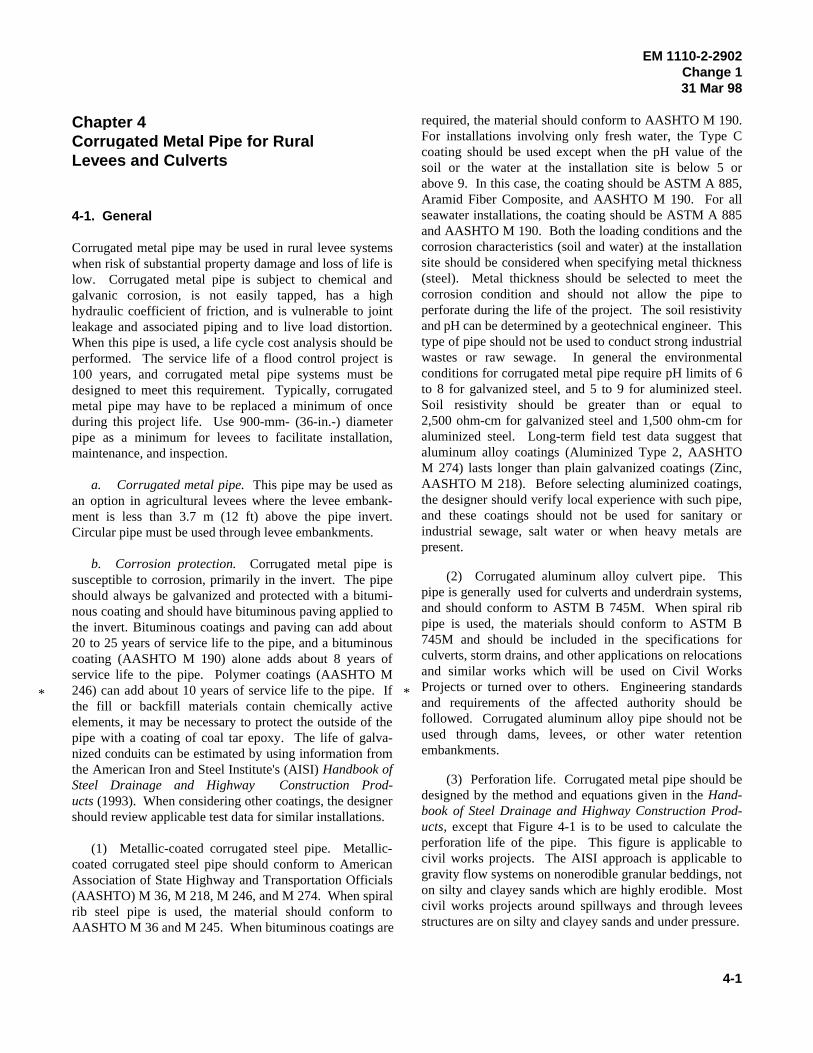
(3) Perforation life. Corrugated metal pipe should bedesigned by the method and equations given in the Hand-book of Steel Drainage and Highway Construction Prod-ucts, except that Figure 4-1 is to be used to calculate theperforation life of the pipe. This figure is applicable tocivil works projects. The AISI approach is applicable togravity flow systems on nonerodible granular beddings, noton silty and clayey sands which are highly erodible. Mostcivil works projects around spillways and through leveesstructures are on silty and clayey sands and under pressure.
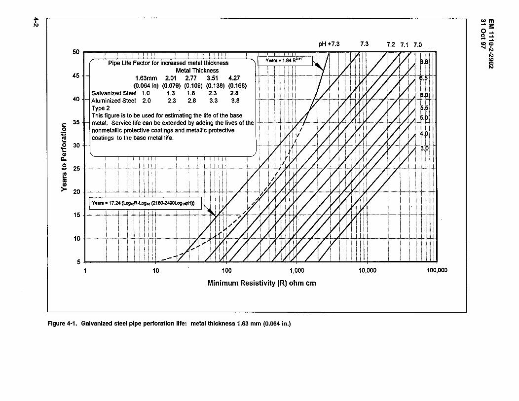
Pipe Life Factor for increased metal thickness Metal Thickness
45 ... 1.63mm 2.01 2.77 3.51 4.27 (0.064 In) (0.079) (0.109) (0.138) (0.168)
Galvanized Steel 1.0 1.3 1.8 2.3 2.8 40 ··· Aluminized Steel 2.0 2.3 2.8 3.3 3.8
c: 0
:;::::: E .g 30 ... (I)
D..
.s 25 ~ CIS
~ 20
15
10
1
Type2
~ j j j j j i . ' .. '
10 100 1,000
Minimum Resistivity (R) ohm em
Figure 4-1. Galvanized steel pipe perforation life: metal thickness 1.63 mm (0.064 in.)
pH +7.3 7.3 7.2 7.1 7.0
10,000 100,000
wm -"S::: o .... n ..... -..... <00 ......
N I
N <0
:G
EM 1110-2-2902Change 131 Mar 98
4-3
*
*
*
*
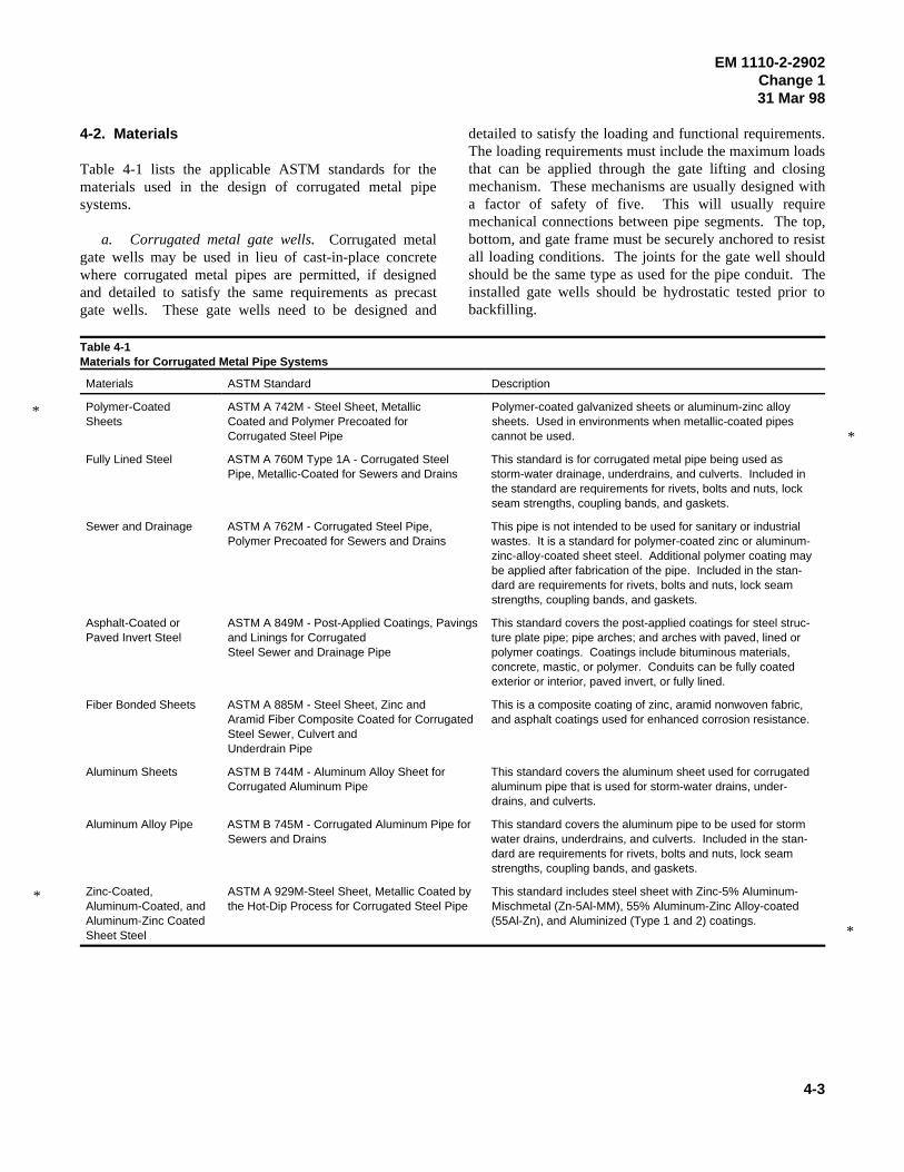
4-2. Materials
Table 4-1 lists the applicable ASTM standards for thematerials used in the design of corrugated metal pipesystems.
a. Corrugated metal gate wells. Corrugated metalgate wells may be used in lieu of cast-in-place concretewhere corrugated metal pipes are permitted, if designedand detailed to satisfy the same requirements as precastgate wells. These gate wells need to be designed and
detailed to satisfy the loading and functional requirements.The loading requirements must include the maximum loadsthat can be applied through the gate lifting and closingmechanism. These mechanisms are usually designed witha factor of safety of five. This will usually requiremechanical connections between pipe segments. The top,bottom, and gate frame must be securely anchored to resistall loading conditions. The joints for the gate well shouldshould be the same type as used for the pipe conduit. Theinstalled gate wells should be hydrostatic tested prior tobackfilling.
Table 4-1Materials for Corrugated Metal Pipe Systems
Materials ASTM Standard Description
Polymer-Coated ASTM A 742M - Steel Sheet, Metallic Polymer-coated galvanized sheets or aluminum-zinc alloySheets Coated and Polymer Precoated for sheets. Used in environments when metallic-coated pipes
Corrugated Steel Pipe cannot be used.
Fully Lined Steel ASTM A 760M Type 1A - Corrugated Steel This standard is for corrugated metal pipe being used asPipe, Metallic-Coated for Sewers and Drains storm-water drainage, underdrains, and culverts. Included in
the standard are requirements for rivets, bolts and nuts, lockseam strengths, coupling bands, and gaskets.
Sewer and Drainage ASTM A 762M - Corrugated Steel Pipe, This pipe is not intended to be used for sanitary or industrialPolymer Precoated for Sewers and Drains wastes. It is a standard for polymer-coated zinc or aluminum-
zinc-alloy-coated sheet steel. Additional polymer coating maybe applied after fabrication of the pipe. Included in the stan-dard are requirements for rivets, bolts and nuts, lock seamstrengths, coupling bands, and gaskets.
Asphalt-Coated or ASTM A 849M - Post-Applied Coatings, Pavings This standard covers the post-applied coatings for steel struc-Paved Invert Steel and Linings for Corrugated ture plate pipe; pipe arches; and arches with paved, lined or
Steel Sewer and Drainage Pipe polymer coatings. Coatings include bituminous materials,concrete, mastic, or polymer. Conduits can be fully coatedexterior or interior, paved invert, or fully lined.
Fiber Bonded Sheets ASTM A 885M - Steel Sheet, Zinc and This is a composite coating of zinc, aramid nonwoven fabric,Aramid Fiber Composite Coated for Corrugated and asphalt coatings used for enhanced corrosion resistance.Steel Sewer, Culvert andUnderdrain Pipe
Aluminum Sheets ASTM B 744M - Aluminum Alloy Sheet for This standard covers the aluminum sheet used for corrugatedCorrugated Aluminum Pipe aluminum pipe that is used for storm-water drains, under-
drains, and culverts.
Aluminum Alloy Pipe ASTM B 745M - Corrugated Aluminum Pipe for This standard covers the aluminum pipe to be used for stormSewers and Drains water drains, underdrains, and culverts. Included in the stan-
dard are requirements for rivets, bolts and nuts, lock seamstrengths, coupling bands, and gaskets.
Zinc-Coated, ASTM A 929M-Steel Sheet, Metallic Coated by This standard includes steel sheet with Zinc-5% Aluminum-Aluminum-Coated, and the Hot-Dip Process for Corrugated Steel Pipe Mischmetal (Zn-5Al-MM), 55% Aluminum-Zinc Alloy-coatedAluminum-Zinc Coated (55Al-Zn), and Aluminized (Type 1 and 2) coatings.Sheet Steel
EM 111 0-2-2902 31 Oct 97
b. Inlet structures. Corrugated metal inlets may be used where corrugated metal pipes are permitted, if designed and detailed to satisfy the loading and functional requirements.
c. Outlet structures. Outlet structures are normally cast-in-place reinforced concrete U-wall structures.
d. Pile bents. When pile bents are used to support a length of pipe, pipe lengths should be limited to 4.9 m (16 ft). Two pile bents, as shown in Figure 3-6, are required for each pipe section when using 2.4-m (8-ft) lengths of pipe, and three pile bents are required when pipe lengths are 4.9 m (16 ft). The two upstream sections of pipe beyond the pile bents should be two half lengths of pipe to develop joint flexibility. Corrugated bands should be used on pipe joints when the pipe is supported on pile bents.
4-3. Installation
Corrugated metal pipe for levees and culverts, and structural plate for culverts should be installed in accordance with the requirements set forth in ASTM A 798 for steel pipe or ASTM A 807 for steel plate pipe or ASTM B 788 for aluminum pipe or ASTM B 789 for aluminum plate pipe.
a. Foundation. When soft soils or rock are encountered, they should be removed and replaced with approved materials as specified herein. The excavation depth below the pipe invert shall be equal to 42 mm (0.5 in.) per meter (foot) of fill above the crown of the pipe, not to exceed 600 mm (24 in.) maximum. The minimum width of material removed in a trench will be three diameters m soft soil, and one and one-half diameters in rock.
b. Backfill. Structural backfill for pipe in trenches is the material placed around the pipe from invert up to an elevation of 305 mm (12 in.) or one-eighth the diameter, whichever is more, above the pipe. For pipe in embankment conditions, structural backfill is the material within one diameter of the sides of the pipe from invert to an elevation of 305 mrn (12 in.), or one-eighth the diameter, whichever is more, over the pipe. Acceptable backfill material for corrugated metal pipe includes silty and clayey gravels and sands (SM and SC, Unified Soil Classification System) as approved by the geotechnical engineer. Gravels and sands (GW, GP, GM, GC, SW, and SP) are not acceptable backfill materials in levees. Plastic clays and silts, organic soils, and peat are not acceptable materials (OL, MH, CH, OH, and PT). This backfill material is installed in 152- to 305-mm (6-to 12-in.)
4-4
layers compacted per EM 1110-2-1913 and is brought up evenly on both sides of the pipe to a minimum cover of 305 mm (12 in) over the top of the pipe.
c. Minimum cover and spacing.
(1) Cover. Use the method for calculating the minimum cover as defined in ASTM A 796 and ASTM B 790 for steel and aluminum, respectively. However, a minimum cover of 610 mm (2 ft) from the top of the pipe to the bottom of the slab or crosstie is recommended for railroads, highways, and airfield pavements. For construction loads, a minimum cover of 1,220 mm (4 ft) is recommended.
(2) Spacing. When multiple lines of pipe are installed in the same excavation, a minimum spacing between pipes of one-half the pipe diameter or 900 mm (3 ft), whichever is less, should be used for adequate compaction of the backfill material. These minimum spacings are for compacted backfill and may be less when using slurry or flowable backfills.
4-4. Loadings
Earth loads and live loads (highway, railways, runways, and impact) for corrugated metal pipe are defined in ASTM A 796 and ASTM B 790 for steel and aluminum, respectively, as vertical pressures. Horizontal pressures are controlled by backfill requirements. The applications of these pressures are similar to those presented in Figure 5-2.
4-5. Methods of Analysis
The design of corrugated steel pipe is covered in ASTM A 796, and the design of corrugated aluminum pipe is covered in ASTM B 790. The designer should consider the design criteria for ring buckling strength, wall crushing strength, handling stiffness, and joint integrity. The section properties for corrugated metal pipe and seam strength requirements are provided in ASTM A 796 for steel and ASTM B 790 for aluminum. When corrugated metal pipe is used, an analysis of seam separation should be performed, except when helical lock seam pipe is used.
a. Thrust in pipe wall. Thrust in pipe walls must satisfy three criteria: required wall area as determined from ring compression or thrust, critical buckling stress, and required seam strength.
(1) Wall thickness. The minimum wall thickness is based on the yield stress of the pipe material, and
EM 1110-2-2902Change 131 Mar 98
4-5
*
assumes a factor of safety of 2. This design is defined in gaskets and bands discussed below are used to developASTM A 796 or ASTM B 790 for steel and aluminum, leak-resistant joints in corrugated metal pipe. A typicalrespectively. hugger band installation is shown in Figure 4-2, and a
(2) Allowable wall stress. The critical buckling wall through levees must be tested for watertightness, andstress can be determined by using formulas presented in require the use of corrugated bands.ASTM A 796 and ASTM B 790, for steel and aluminum,respectively. If the critical buckling stress is less than the a. Gaskets. For sleeve type gaskets, use ASTMyield stress of the wall material, recalculate the required D 1056, Grade 2C2. Sleeve type gaskets should be one-wall thickness using the calculated buckling stress. piece construction, closed-cell neoprene, skin on all four
(3) Longitudinal seam stress. Because there are no 13 mm (1/2 in.) less than the width of the connection bandseams in helical lock seam and welded seam pipe, these required. O-ring gaskets should meet the requirements ofcriteria do not apply. For pipe fabricated with longitudinal ASTM C 361.seams (riveted, spot-welded, or bolted), seam strengthshould be sufficient to develop the thrust in the pipe wall. b. Coupling bands. Corrugated bands and sleeveThe factor of safety for longitudinal seams is 3. Also, these type gasket are required when watertightness is a concern.joints must be hydrostatically tested for acceptance. Seam For helical pipe, the ends should be reformed so the pipesstrengths for various seam connections are given in ASTM can be coupled. Flat bands with sleeve or O-ring typeA 796 and B 790 for steel and aluminum pipe, respectively. gaskets, or hat-channels with mastic bands are not accept-
b. Handling stiffness. The handling stiffness of cor- apart. Bands with annular corrugations and rod and lugrugated metal pipe should be checked to ensure that the connectors, semi-corrugated bands and bands with angularpipe can be handled without damage during construction. corrugations, and angle iron bolt connectors are acceptableThe required flexibility factors for steel and aluminum connectors.pipe are given in ASTM A 796 and ASTM B 790,respectively.
4-6. Joints Where considerable foundation settlement is likely to
Special attention should be given to the joint between a and to accommodate the extension of the pipe due tocorrugated metal pipe and any concrete structure. The settlement.
typical corrugated band joint is shown in Figure 4-3. Joints
sides. The thickness should be 9.53 mm (3/8 in.) and
able for watertight joints as they are susceptible to pulling
4-7. Camber
occur, camber should be used to ensure positive drainage
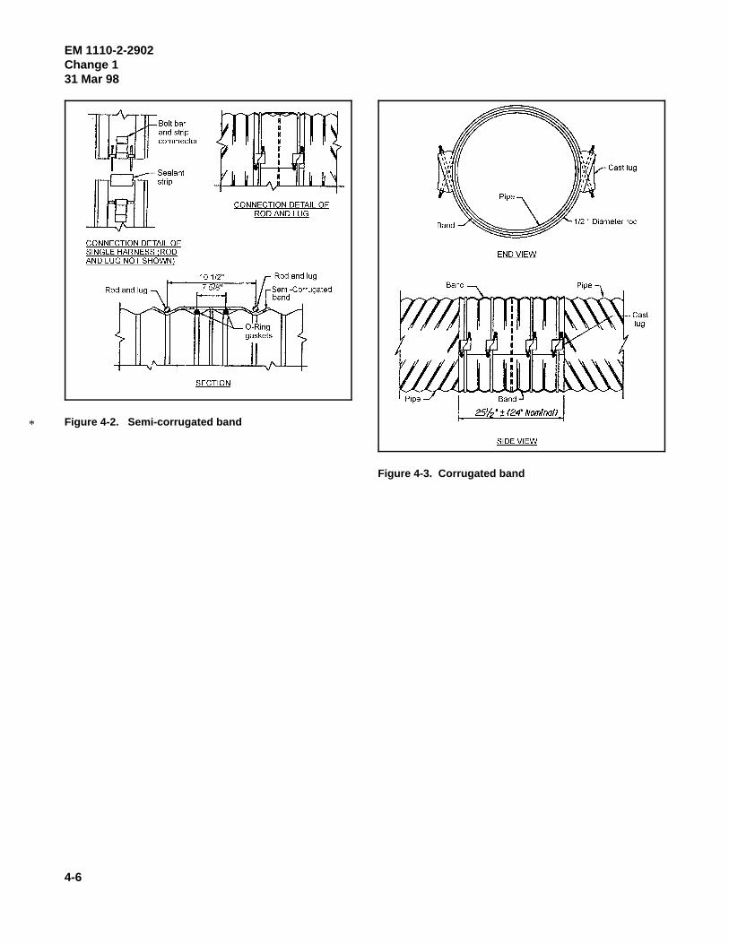
EM 1110-2-2902Change 131 Mar 98
4-6
Figure 4-2. Semi-corrugated band *
Figure 4-3. Corrugated band
Chapter 5 Concrete Culverts
5-1. Features Affecting Structure Shape and Capacity
The following information applies to the design of reinforced concrete culverts. Typical conduit shapes used for culverts are shown in Figure 5-1.
a. Location. Ideally, the axis of a culvert should coincide with that of the natural streambed and the structure should be straight and short. This may require modification of the culvert alignment and grade. Often it is more practical to construct the culvert at right angles to the roadway. However, the cost of any change in stream channel location required to accomplish this should be balanced against the cost of a skewed alignment of the culvert, and changes in channel hydraulics should be considered.
b. Grade and camber. The culvert invert gradient should be the same as the natural streambed to minimize erosion and silting problems. Foundation settlement should be countered by cambering the culvert to ensure positive drainage.
c. Entrance and outlet conditions. It is often necessary to enlarge the natural channel a considerable distance downstream of the culvert to prevent backwater from entering the culvert. Also, enlargement of the culvert entrance may be required to prevent ponding above the culvert entrance. The entrance and outlet conditions of the culvert structure directly impact its hydraulic capacity. Rounding or beveling the entrance corners increases the hydraulic capacity, especially for short culverts of small cross section. Scour problems can occur when abrupt changes are made to the streambed flow line at the entrance or outlet of the culvert.
5-2. Materials
Table 5-l lists the applicable standards for the materials used in the design of reinforced concrete culverts.
5-3. Installation
a. Foundation material. Materials to be used for the culvert pipe foundation should be indicated on the drawings. Refer to the geotechnical foundation report for the project.
EM 111 0-2-2902 31 Oct 97
b. Bedding materials. Bedding class and materials for culverts should be indicated on the drawings. Beddings shown in the American Concrete Pipe Association's Concrete Pipe Design Manual (1992) are acceptable. When designing the bedding for a box culvert, assume the bedding material to be slightly yielding, and that a uniform support pressure develops under the box section.
5-4. Loadings
Assume that design loads for concrete culvert pipe are calculated as vertical pressures and that the horizontal pressures are controlled by the backfill requirements. Refer to Chapter 2 for typical loading calculations. Concentrated live loads for highway or railroad loadings should be applied as required by the standards of the affected authority and in accordance with Chapter 2 of this manual.
a. Railroad, highway, and aircraft loads. Culverts designed for loadings from railroads, highways, or aircraft need to satisfy the criteria of the affected authority. This manual presents data closely related to the requirements of the American Railway Engineering Association (AREA) (1996) and the American Association of State Highway Transportation Officials (AASHTO) Standard Specifications for Highway Bridges (AASHTO 1996). The method used to combine wheel live loads and earth loads on culverts is shown in Figure 5-2. The procedure presented in the Concrete Pipe Design Manual (American Concrete Pipe Association 1992) should be used to distribute aircraft wheel loads through pavement slabs to the top of the culvert. Railroad or highway loads may be ignored when the induced vertical stress fields are equal to or Jess than 4.8 kPa (100 psf), a depth of 2.4 m (8 ft) for highway loadings, or 9 m (30 ft) for railroad loadings. Note that the railroad and highway loads as shown are in accordance with ASTM A 796 and include an impact factor of 50 percent, which is higher than the impact loads required by AREA or AASHTO criteria.
b. Special point loads. Pressure bulb charts are acceptable for determining the nominal vertical stress fields from relatively small footings. Pressure bulbs for continuous and circular/square footings are shown in Figures 5-3 and 5-4, respectively. Consult a geotechnical engineer for lateral loads from surface surcharge loadings.
5-1
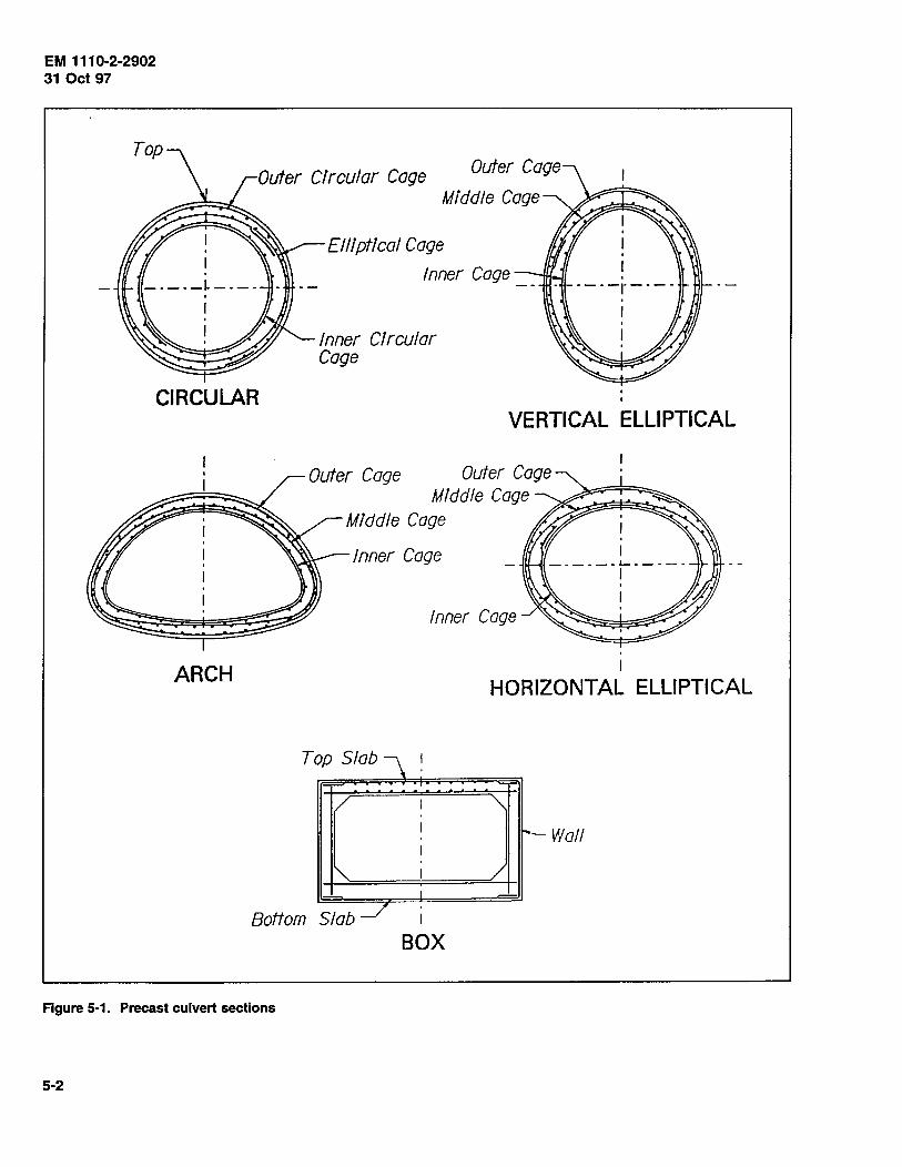
EM 1110-2-2902 31 Oct 97
Outer Circular Cage Outer Cage
Middle Cage
Elliptical Cage
Inner Cage
Inner Circular Cage
CIRCULAR
ARCH
VERTICAL ELLIPTICAL
Outer Cage Middle Cage
Middle Cage
Inner Cage
Inner Cage
' I
HORIZONTAL ELLIPTICAL
Top Slab ~
I "' I ~ Wall I
"- I / - I -
_/ Bottom Slab 1
BOX
Figure 5-1. Precast culvert sections
5-2
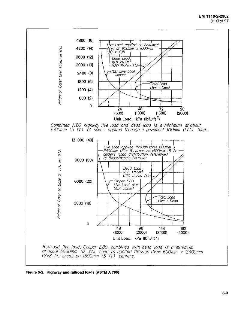
EM 1110-2-2902 31 Oct 97
4800 (16)
-- 4200 (14) ....: ~
~ 3600 (12) ~
,g 3000 (10) Q_
'--Cl,) 2400 (8) () '-- 1800 (6) Cl,)
8 ....... 1200 (4) 0
l:: 600 (2) t:h ·-Cl,)
::r:: 0
24 48 72 96· (500) (1000) (1500) (2000)
Unit Load, kPa (lbf./ft 2)
Combined H20 higtwoy live load and dead load is a minimum at about 1500mm (5 ft.J of cover. applied through a pavement 300mm (f ft.J thick.
12 000 (40)
9000 (30)
.~ 1---
6000 (20)
3000 (10)
0
Live Lood applied through three 600mm x 2400mm (2' x 8'J areas on 1500mm r5 ft.J centers (Lood distribution determined by Boussinesq's formula)
Dead Load 1--\--+---1- 18.8 kN I m 3
n20 lb.lcu ft.J Cooper E80
t-----+-lf--Li~'e Lood plus·-+-~'-+-+--+---+----1 50/. Impact
Total Lood Live+ Dead
48 96 1M (1000) (2000) (3000)
Unit Load, kPa (lbf./ft 2 )
192 (4000)
Railroad live load. Cooper EBO. combined with dead load is a mtmmum at about 3600mm (12 ft.J Load is applied through three 600mm x 2400mm r2x8 ft.J areas on 1500mm (5 ft.J centers.
Figure 5-2. Highway and railroad loads (ASTM A 796)
5-3
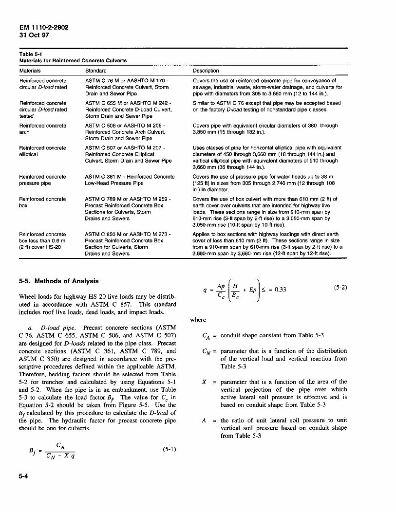
EM 1110-2-2902 31 Oct 97
Table 5-1 Materials for Reinforced Concrete Culverts
Materials
Reinforced concrete circular 0-/oad rated
Reinforced concrete circular 0-/oad rated tested
Reinforced concrete arch
Reinforced concrete elliptical
Reinforced concrete pressure pipe
Reinforced concrete box
Reinforced concrete box less than 0.6 m (2 ft) cover HS-20
Standard
ASTM C 76 M or AASHTO M 170 -Reinforced Concrete Culvert, Storm Drain and Sewer Pipe
ASTM C 655 M or AASHTO M 242 -Reinforced Concrete D-Load Culvert, Storm Drain and Sewer Pipe
ASTM C 506 or AASHTO M 206 -Reinforced Concrete Arch Culvert, Storm Drain and Sewer Pipe
ASTM C 507 or AASHTO M 207 -Reinforced Concrete Elliptical Culvert, Storm Drain and Sewer Pipe
ASTM C 361 M - Reinforced Concrete Low-Head Pressure Pipe
ASTM C 789 M or AASHTO M 259 -Precast Reinforced Concrete Box Sections for Culverts, Storm Drains and Sewers
ASTM C 850 M or AASHTO M 273 -Precast Reinforced Concrete Box Section for Culverts, Storm Drains and Sewers
5-5. Methods of Analysis
Wheel loads for highway HS 20 live loads may be distributed in accordance with ASTM C 857. This standard includes roof live loads, dead loads, and impact loads.
a. D-load pipe. Precast concrete sections (ASTM C 76, ASTM C 655, ASTM C 506, and ASTM C 507) are designed for D-loads related to the pipe class. Precast concrete sections (ASTM C 361, ASTM C 789, and ASTM C 850) are designed in accordance with the prescriptive procedures defined within the applicable ASTM. Therefore, bedding factors should be selected from Table 5-2 for trenches and calculated by using Equations 5-l and 5-2. When the pipe is in an embankment, use Table 5-3 to calculate the load factor Bl The value for Cc in Equation 5-2 should be taken from Figure 5-5. Use the B1
calculated by this procedure to calculate the D-load of the pipe. The hydraulic factor for precast concrete pipe should be one for culverts.
(5-1)
5-4
Description
Covers the use of reinforced concrete pipe for conveyance of sewage, industrial waste, storm-water drainage, and culverts for pipe with diameters from 305 to 3,660 mm (12 to 144 in.).
Similar to ASTM C 76 except that pipe may be accepted based on the factory 0-/oad testing of nonstandard pipe classes.
Covers pipe with equivalent circular diameters of 380 through 3,350 mm (15 through 132 in.).
Uses classes of pipe for horizontal elliptical pipe with equivalent diameters of 450 through 3,660 mm (18 through 144 in.) and vertical elliptical pipe with equivalent diameters of 910 through 3,660 mm (36 through 144 in.).
Covers the use of pressure pipe for water heads up to 38 m (125ft) in sizes from 305 through 2,740 mm (12 through 108 in.) in diameter.
Covers the use of box culvert with more than 610 mm (2 ft) of earth cover over culverts that are intended for highway live loads. These sections range in size from 91 0-mm span by 610-mm rise (3-ft span by 2-ft rise) to a 3,050-mm span by 3,050-mm rise (10-ft span by 10-ft rise).
Applies to box sections with highway loadings with direct earth cover of less than 610 mm (2 ft). These sections range in size from a 910-mm span by 610-mm rise (3-ft span by 2-ft rise) to a 3,660-mm span by 3,660-mm rise (12-ft span by 12-ft rise).
Ap [H l q = _ _ + Ep ::;; = 0.33 Cc Be
(5-2)
where
CA = conduit shape constant from Table 5-3
C N = parameter that is a function of the distribution of the vertical load and vertical reaction from Table 5-3
X = parameter that is a function of the area of the vertical projection of the pipe over which active lateral soil pressure is effective and is based on conduit shape from Table 5-3
A = the ratio of unit lateral soil pressure to unit vertical soil pressure based on conduit shape from Table 5-3
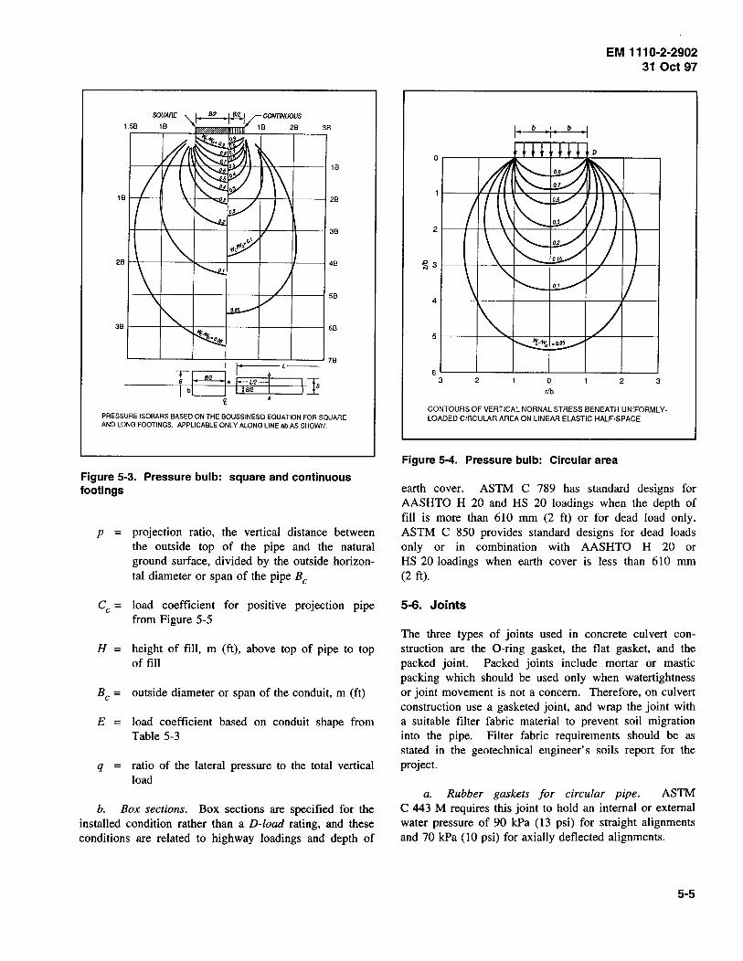
'----~--~--~~~==~==~7B I I' L--
----~T~b~r-M~·mT.M~~j1b--4\} <t •
PRESSURE ISOBARS BASED ON THE BOUSSINESQ EQUATION FOR SQUARE AND LONG FOOTINGS. APPLICABLE ONLY ALONG LINE ab AS SHOWN.
Figure 5-3. Pressure bulb: square and continuous footings
p = projection ratio, the vertical distance between the outside top of the pipe and the natural ground surface, divided by the outside horizontal diameter or span of the pipe B c
Cc = load coefficient for positive projection pipe from Figure 5-5
H = height of fill, m (ft), above top of pipe to top of fill
Be= outside diameter or span of the conduit, m (ft)
E = load coefficient based on conduit shape from Table 5-3
q = ratio of the lateral pressure to the total vertical load
b. Box sections. Box sections are specified for the installed condition rather than a D-load rating, and these conditions are related to highway loadings and depth of
EM 1110-2-2902 31 Oct 97
2
~ 3
4
5
6 3 2 0 2 3
rib
CONTOURS OF VERTICAL NORNAL STRESS BENEATH UNIFORMLY· LOADED CIRCULAR AREA ON LINEAR ELASTIC HALF·SPACE
Figure 5-4. Pressure bulb: Circular area
earth cover. ASTM C 789 has standard designs for AASHTO H 20 and HS 20 loadings when the depth of fill is more than 610 mm (2 ft) or for dead load only. ASTM C 850 provides standard designs for dead loads only or in combination with AASHTO H 20 or HS 20 loadings when earth cover is less than 610 mm (2 ft).
5-6. Joints
The three types of joints used in concrete culvert construction are the 0-ring gasket, the flat gasket, and the packed joint. Packed joints include mortar or mastic packing which should be used only when watertightness or joint movement is not a concern. Therefore, on culvert construction use a gasketed joint, and wrap the joint with a suitable filter fabric material to prevent soil migration into the pipe. Filter fabric requirements should be as stated in the geotechnical engineer's soils report for the project.
a. Rubber gaskets for circular pipe. ASTM C 443 M requires this joint to hold an internal or external water pressure of 90 kPa (13 psi) for straight alignments and 70 kPa (10 psi) for axially deflected alignments.
5-5

EM 1110-2-2902 31 Oct 97
Table 5·2 Design Value Parameters for Load Factor: Trenches
Shape Bedding Cradle Reinforcement Bedding Factor (B~
Circular (only) A (Concrete) A5 = 1.0% 0.4
4.8 3.4 2.8 0.0 (Plain Concrete)
All shapes
All shapes
Circular (only)
Table 5·3
B (Shaped)
C (Shaped)
D (Impermissible: Flat)
Design Value Parameters for Load Factor: Embankments
Shape C A (Shape Factor)
Circular: A = 0.33, E = 0.50
1.431
Bedding Class
Class B (Shaped) Class C (Shaped)
Horizontal Elliptical and Arch: A = 0.23, E = 0.35
1.337 Class B Class C
Vertical Elliptical: A= 0.48, E = 0.73
1.021 Class B Class C
b. External band gaskets for noncircular pipe. ASTM C 877 applies to arch, elliptical, and box pipe sections. These sealing bands are adequate for external hydrostatic pressures of up to 90 kPa (13 psi). Joints on the installed pipe should be tested when watertightness is a concern. Sealing bands that meet this standard can be rubber and mastic or plastic ftlm and mesh-reinforced mastic.
c. Field pipe joint testing. When watertight joints are required, one of the test methods referenced below should be used.
(1) Low-pressure air test. ASTM C 924 covers exftltration testing of 100- to 61Q-mm (4- to 24-in.) concrete pipe with gasketed joints and demonstrates the condition of the pipe prior to backfilling.
5-6
CN (Distribution Factor)
0.707 0.840
0.630 0.763
0.516 0.615
1.9
1.5
1.1
Projection Ratio, p
1.0 0.9 0.7 0.5 0.3 0.0
0.9 0.7 0.5 0.3
0.9 0.7 0.5 0.3
X (Lateral Projection Factor)
0.638 0.655 0.594 0.423 0.217 0.000
0.421 0.369 0.268 0.148
0.718 0.639 0.457 0.238
(2) Infiltration/exftltration test. ASTM C 969 covers the testing of concrete pipes up to 210 m (700 ft) in length between manholes. The inftltration test is used when the groundwater level is 1,800 mm (6 ft) above the crown of the pipe and allows a leakage including manholes of 18.5 L/(mm-diameter) (km) (24 hr) ((200 gal/ (in.-diameter) (mile) (24 hr)). The exfiltration test is used when the groundwater level is 910 mm (3 ft) below the invert of the pipe and allows a leakage including manholes of 18.5 L/(mm-diameter) (km) (24 hr) ((200 gal/ (in.-diameter) (mile) (24 hr)) with an average head of 0.9 m (3 ft) or less. The Corps of Engineers exfiltration test allows a leakage rate of 23.1 L/(mm-diameter) (km) (24 hr) ((250 gal/(in.-diameter) (mile) (24 hr)) for pipeline construction. This test method does not apply to water retention structures.
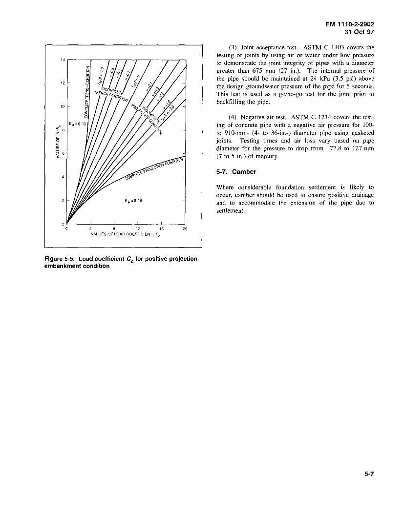
lL 0 rJ) w :::J
12
10
;t 6 >
4
2
4 12 16 20 VALUES OF LOAD COEFFICIENT, Cc
Figure 5-5. Load coefficient Cc for positive projection embankment condition
EM 111 0-2-2902 31 Oct 97
(3) Joint acceptance test. ASTM C 1103 covers the testing of joints by using air or water under low pressure to demonstrate the joint integrity of pipes with a diameter greater than 675 mm (27 in.). The internal pressure of the pipe should be maintained at 24 kPa (3.5 psi) above the design groundwater pressure of the pipe for 5 seconds. This test is used as a go/no-go test for the joint prior to backfilling the pipe.
(4) Negative air test. ASTM C 1214 covers the testing of concrete pipe with a negative air pressure for 100-to 910-mm- (4- to 36-in.-) diameter pipe using gasketed joints. Testing times and air loss vary based on pipe diameter for the pressure to drop from 177.8 to 127 mm (7 to 5 in.) of mercury.
5-7. Camber
Where considerable foundation settlement is likely to occur, camber should be used to ensure positive drainage and to accommodate the extension of the pipe due to settlement.
5-7
Chapter 6 Plastic Pipe for Other Applications
6-1. General
a. Plastic pipes. Plastic pipes are available in both solid wall and profile wall thermoplastic acrylonitrilebutadiene-styrene (ABS), high-density polyethylene (HDPE), and polyvinyl chloride (PVC) pipes, as well as thermoset reinforced plastic mortar (RPM) pipes. They all possess the general attributes normally associated with plastics including light weight, long lengths, tight joints, and resistance to normal atmospheric corrosion. All these pipes are flexible, and in general the design considerations are similar to metal pipes. However, due to the viscoelastic nature of these materials, the time under load condition may require that long-term material properties be used in the design. Additionally, each specific grade of material, as well as the type of pipe (i.e., solid or profile) dictates the design properties.
b. Selection considerations. Plastic pipes vary significantly in strength, stiffness, and performance. Differences depend more on their design and intended use than on the specific pipe wall material. A thorough evaluation of the intended use and detailed material, jointing, and backfill specifications is necessary to ensure performance. Use of plastic pipes in drainage and subdrainage applications is increasing. However, their use in low cover with heavy wheel loads or high cover applications is limited (refer to paragraph 6-3). Plastic pipe will not be used through embankments of dams and levees without approval from HQUSACE. Plastic pipes will typically be used for drainage piping behind structures.
6-2. Materials
a. Plastic materials. The piping materials discussed in this chapter include ABS, HDPE, and PVC thermoplastic pipes and RPM thermosetting resin pipes. Thermoplastic pipes include both solid wall (smooth, solid pipe wall extrusions), as well as profile wall (corrugated, ribbed, etc.) pipes that provide the indicated level of pipe stiffness while providing a limited wall area to carry ring compression.
b. Profile wall pipe. These pipes are commonly more economical, especially in diameters exceeding 200 mm (8 in.). However, they provide 50 to 70 percent of the wall area when compared to equal stiffness solid wall pipes of the same material. This limits their
EM 111 0-2-2902 31 Oct 97
load-carrying capability in high cover applications and also limits beam strength.
c. Reinforced plastic mortar. These pipes are strain sensitive. If the surface resin layer strain cracks, the reinforcing glass is exposed to corrosion. The manufacturer will supply strain limits which are typically in the 0.5 to 1.0 percent range. Control of deflection and localized deformation are very important in design and construction.
d. Plastic pipe systems. These systems are summarized in Table 6-1. Typical mechanical properties for plastic pipe design are shown in Table 6-2, and average values for the modulus of soil reaction are shown in Table 6-3.
e. Applications. Intended applications are provided in the American Society for Testing and Materials (ASTM) or American Association of State Highway and Transportation Officials (AASHTO) specification. The highest (most stringent) use is summarized above. Generally, piping systems can be downgraded in application and provide excellent performance, but they cannot be upgraded. Sanitary sewer pipes perform well in culvert, drainage, and subdrainage (if perforations are provided) applications. However, unperforated land drainage pipes do not perform well as culverts or sewers.
(1) Culverts. For culvert applications, the exposed ends of some types of plastic pipes need protection from exposure to ultraviolet, thermal cycling, etc. Concrete or metal end sections, headwalls, or other end protection is recommended.
(2) Pipe stiffness. Product specifications typically provide minimum pipe stiffness levels. Pipe stiffness and its relationship to AASHTO Flexibility Factor (FF) limits for adequate installation stiffness are provided in paragraph 6-5. In installations where poorly graded granular (SP, GP, etc.) or cohesive (CL or ML) backfill materials are to be used, specifying a stiffer pipe than required by the minimum design criteria is recommended (refer to paragraph 6-5).
(3) Gravity flow. The listed materials, except as noted, are gravity flow piping systems limited to applications where internal hydrostatic heads will not exceed 7.6 m (25 ft) of water.
f. Joints. The types of joints available for each system are shown in Table 6-4. When watertight joints
6-1
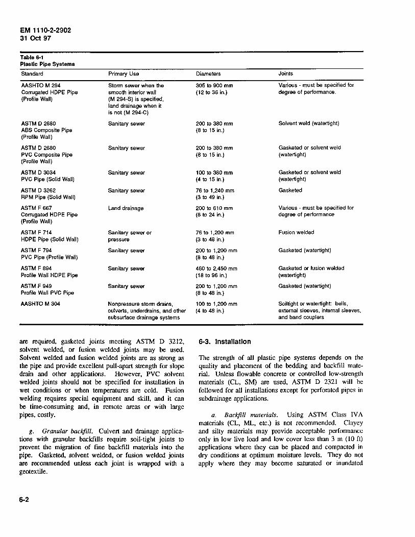
EM 111 0-2-2902 31 Oct 97
Table 6-1 Plastic Pipe Systems
Standard Primary Use
AASHTO M 294 Storm sewer when the Corrugated HOPE Pipe smooth interior wall (Profile Wall) (M 294-S) is specified,
land drainage when it is not (M 294-C)
ASTM D 2680 Sanitary sewer ABS Composite Pipe (Profile Wall)
ASTM D 2680 Sanitary sewer PVC Composite Pipe (Profile Wall)
ASTM D 3034 Sanitary sewer PVC Pipe (Solid Wall)
ASTM D 3262 Sanitary sewer RPM Pipe (Solid Wall)
ASTM F667 Land drainage Corrugated HOPE Pipe (Profile Wall)
ASTM F 714 Sanitary sewer or HOPE Pipe (Solid Wall) pressure
ASTM F 794 Sanitary sewer PVC Pipe (Profile Wall)
ASTM F 894 Sanitary sewer Profile Wall HOPE Pipe
ASTM F 949 Sanitary sewer Profile Wall PVC Pipe
AASHTO M 304 Nonpressure storm drains, culverts, underdrains, and other subsurface drainage systems
are required. gasketed joints meeting ASTM D 3212, solvent welded, or fusion welded joints may be used. Solvent welded and fusion welded joints are as strong as the pipe and provide excellent pull-apart strength for slope drain and other applications. However, PVC solvent welded joints should not be specified for installation in wet conditions or when temperatures are cold. Fusion welding requires special equipment and skill, and it can be time-consuming and, in remote areas or with large pipes, costly.
g. Granular backfill. Culvert and drainage applications with granular backfills require soil-tight joints to prevent the migration of fine backfill materials into the pipe. Gasketed, solvent welded, or fusion welded joints are recommended unless each joint is wrapped with a geotextile.
6-2
Diameters Joints
305 to 900 mm Various - must be specified for (12 to 36 in.) degree of performance.
200 to 380 mm Solvent weld (watertight) (8 to 15 in.)
200 to 380 mm Gasketed or solvent weld (8 to 15 in.) (watertight)
100 to 380 mm Gasketed or solvent weld (4 to 15 in.) (watertight)
76 to 1 ,240 mm Gasketed (3 to 49 in.)
200 to 610 mm Various - must be specified for (8 to 24 in.) degree of performance
76 to 1 ,200 mm Fusion welded (3 to 48 in.)
200 to 1,200 mm Gasketed (watertight) (8 to 48 in.)
460 to 2,450 mm Gasketed or fusion welded (18 to 96 in.) (watertight)
200 to 1,200 mm Gasketed (watertight) (8 to 48 in.)
100 to 1,200 mm Soiltight or watertight: bells, (4 to 48 in.) external sleeves, internal sleeves,
and band couplers
6-3. Installation
The strength of all plastic pipe systems depends on the quality and placement of the bedding and backfill material. Unless flowable concrete or controlled low-strength materials (CL, SM) are used, ASTM D 2321 will be followed for all installations except for perforated pipes in subdrainage applications.
a. Backfill materials. Using ASTM Class IV A materials (CL, ML, etc.) is not recommended. Clayey and silty materials may provide acceptable performance only in low live load and low cover less than 3 m (10 ft) applications where they can be placed and compacted in dry conditions at optimum moisture levels. They do not apply where they may become saturated or inundated
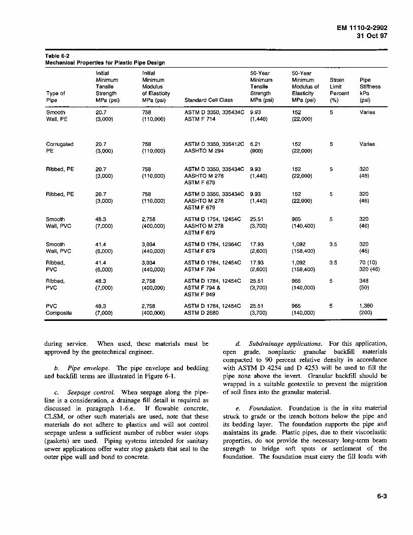
EM 1110-2-2902 31 Oct 97
Table 6-2 Mechanical Properties for Plastic Pipe Design
Initial Initial 50-Year 50-Year Minimum Minimum Minimum Minimum Strain Pipe Tensile Modulus Tensile Modulus of Limit Stiffness
Type of Strength of Elasticity Strength Elasticity Percent kPa Pipe MPa (psi) MPa (psi) Standard Cell Class MPa (psi) MPa (psi) (%) (psi)
Smooth 20.7 758 ASTM D 3350, 335434C 9.93 152 5 Varies Wall, PE (3,000) (110,000) ASTM F 714 (1 ,440) (22,000)
Corrugated 20.7 758 ASTM D 3350, 335412C 6.21 152 5 Varies PE (3,000) (110,000) AASHTO M 294 (900) (22,000)
Ribbed, PE 20.7 758 ASTM D 3350, 335434C 9.93 152 5 320 (3,000) (11 0,000) AASHTO M 278 (1,440) (22,000) (46)
ASTM F 679
Ribbed, PE 20.7 758 ASTM D 3350, 335434C 9.93 152 5 320 (3,000) (110,000) AASHTO M 278 (1 ,440) (22,000) (46)
ASTM F 679
Smooth 48.3 2,758 ASTM D 1754, 12454C 25.51 965 5 320 Wall, PVC (7,000) (400,000) AASHTO M 278 (3,700) (140,400) (46)
ASTM F 679
Smooth 41.4 3,034 ASTM D 1784, 12364C 17.93 1,092 3.5 320 Wall, PVC (6,000) (440,000) ASTM F 679 (2,600) (158,400) (46)
Ribbed, 41.4 3,034 ASTM D 1784, 12454C 17.93 1,092 3.5 70 (10) PVC (6,000) (440,000) ASTM F 794 (2,600) (158,400) 320 (46)
Ribbed, 48.3 2,758 ASTM D 1784, 12454C 25.51 965 5 348 PVC (7,000) (400,000) ASTM F 794 & (3,700) (140,000) (50}
ASTM F 949
PVC 48.3 2,758 ASTM D 1784, 12454C 25.51 965 5 1,380 Composite (7,000) (400,000) ASTM D 2680 (3,700) (140,000) (200)
during service. When used, these materials must be approved by the geotechnical engineer.
d. Subdrainage applications. For this application, open grade, nonplastic granular backfill materials compacted to 90 percent relative density in accordance with ASTM D 4254 and D 4253 will be used to fill the pipe zone above the invert. Granular backfill should be wrapped in a suitable geotextile to prevent the migration of soil fines into the granular material.
b. Pipe envelope. The pipe envelope and bedding and backfill terms are illustrated in Figure 6-1.
c. Seepage control. When seepage along the pipeline is a consideration, a drainage fill detail is required as discussed in paragraph l-6.e. If flowable concrete, CLSM, or other such materials are used, note that these materials do not adhere to plastics and will not control seepage unless a sufficient number of rubber water stops (gaskets) are used. Piping systems intended for sanitary sewer applications offer water stop gaskets that seal to the outer pipe wall and bond to concrete.
e. Foundation. Foundation is the in situ material struck to grade or the trench bottom below the pipe and its bedding layer. The foundation supports the pipe and maintains its grade. Plastic pipes, due to their viscoelastic properties, do not provide the necessary long-term beam strength to bridge soft spots or settlement of the foundation. The foundation must carry the fill loads with
6-3
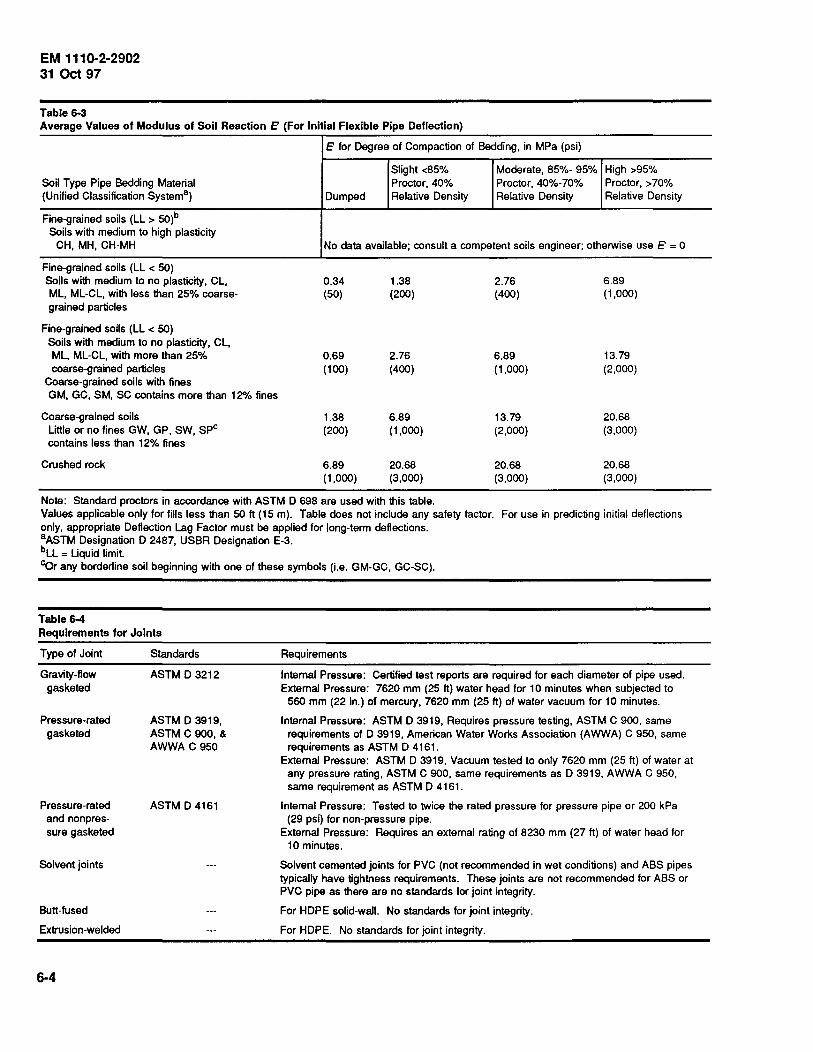
EM 1110-2-2902 31 Oct 97
Table 6-3 Average Values of Modulus of Soil Reaction E' (For Initial Flexible Pipe Deflection)
Soil Type Pipe Bedding Material (Unified Classification System2
)
Fine-grained soils (LL > 50)b Soils with medium to high plasticity
CH, MH, CH-MH
Fine-grained soils (LL < 50) Soils with medium to no plasticity, CL, ML, ML-CL, with less than 25% coarsegrained particles
Fine-grained soils (LL < 50) Soils with medium to no plasticity, CL, ML, ML-CL, with more than 25% coarse-grained particles
Coarse-grained soils with fines GM, GC, SM, SC contains more than 12"/o fines
Coarse-grained soils Little or no fines GW, GP, SW, spc contains less than 12% fines
Crushed rock
e for Degree of Compaction of Bedding, in MPa (psi)
Slight <85% Moderate, 85%- 95% High >95% Proctor, 40% Proctor, 40%-70% Proctor, >70%
Dumped Relative Density Relative Density Relative Density
No data available; consult a competent soils engineer; otherwise use e = 0
0.34 (50)
0.69 (100)
1.38 (200)
6.89 (1,000)
1.38 (200)
2.76 (400)
6.89 (1,000)
20.68 (3,000)
2.76 (400)
6.89 (1,000)
13.79 (2,000)
20.68 (3,000)
6.89 (1,000)
13.79 (2,000)
20.68 (3,000)
20.68 (3,000)
Note: Standard proctors in accordance with ASTM D 698 are used with this table. Values applicable only for fills less than 50ft (15m). Table does not include any safety factor. For use in predicting initial deflections only, appropriate Deflection Lag Factor must be applied for long-term deflections. 8 ASTM Designation D 2487, USBR Designation E-3. bLL = Liquid limit. cOr any borderline soil beginning with one of these symbols (i.e. GM-GC, GC-SC).
Table 6-4 Requirements for Joints
Type of Joint
Gravity-flow gasketed
Pressure-rated gasketed
Pressure-rated and nonpressure gasketed
Solvent joints
Butt-fused
Extrusion-welded
6-4
Standards
ASTM D 3212
ASTM D 3919, ASTM C 900, & AWWA C 950
ASTM D 4161
Requirements
Internal Pressure: Certified test reports are required for each diameter of pipe used. External Pressure: 7620 mm (25 ft) water head for 10 minutes when subjected to
560 mm (22 in.) of mercury, 7620 mm (25ft) of water vacuum for 10 minutes.
Internal Pressure: ASTM D 3919, Requires pressure testing, ASTM C 900, same requirements of D 3919, American Water Works Association (AWWA) C 950, same requirements as ASTM D 4161.
External Pressure: ASTM D 3919, Vacuum tested to only 7620 mm (25ft) of water at any pressure rating, ASTM C 900, same requirements as D 3919, AWWA C 950, same requirement as ASTM D 4161 .
Internal Pressure: Tested to twice the rated pressure for pressure pipe or 200 kPa (29 psi) for non-pressure pipe.
External Pressure: Requires an external rating of 8230 mm (27 ft) of water head for 10 minutes.
Solvent cemented joints for PVC (not recommended in wet conditions) and ABS pipes typically have tightness requirements. These joints are not recommended for ABS or PVC pipe as there are no standards for joint integrity.
For HOPE solid-wall. No standards for joint integrity.
For HOPE. No standards for joint integrity.

Final backfill
Initial Backfill
Pipe zone Haunchlng
~-+
Bedding
Foundation
TYPICAL PIPE BACKFILL
Final backfill
Pipe zone Flowab/e backfill
Foundation
FLOWABLE PIPE BACKFILL
Figure 6-1. Flexible pipe backfill
EM 1110-2-2902 31 Oct 97
6-5
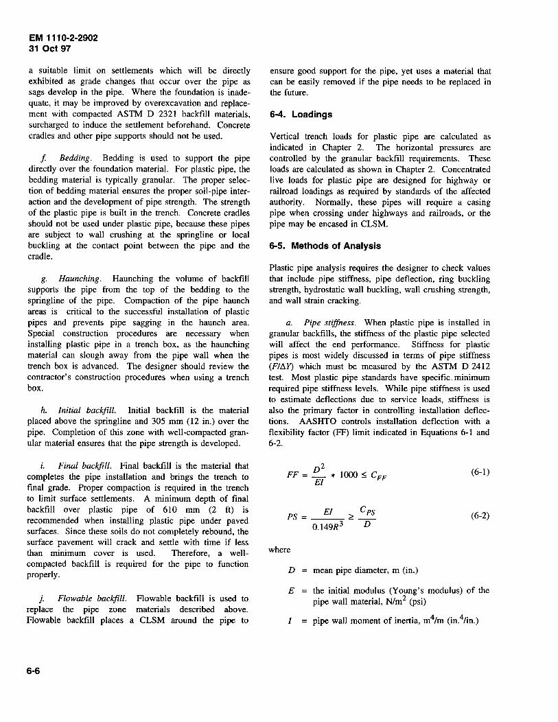
EM 1110-2-2902 31 Oct 97
a suitable limit on settlements which will be directly exhibited as grade changes that occur over the pipe as sags develop in the pipe. Where the foundation is inadequate, it may be improved by overexcavation and replacement with compacted ASTM D 2321 backfill materials, surcharged to induce the settlement beforehand. Concrete cradles and other pipe supports should not be used.
f Bedding. Bedding is used to support the pipe directly over the foundation material. For plastic pipe, the bedding material is typically granular. The proper selection of bedding material ensures the proper soil-pipe interaction and the development of pipe strength. The strength of the plastic pipe is built in the trench. Concrete cradles should not be used under plastic pipe, because these pipes are subject to wall crushing at the springline or local buckling at the contact point between the pipe and the cradle.
g. Haunching. Haunching the volume of backfill supports the pipe from the top of the bedding to the springline of the pipe. Compaction of the pipe haunch areas is critical to the successful installation of plastic pipes and prevents pipe sagging in the haunch area. Special construction procedures are necessary when installing plastic pipe in a trench box, as the haunching material can slough away from the pipe wall when the trench box is advanced. The designer should review the contractor's construction procedures when using a trench box.
h. Initial backfill. Initial backfill is the material placed above the springline and 305 mm (12 in.) over the pipe. Completion of this zone with well-compacted granular material ensures that the pipe strength is developed.
i. Final backfill. Final backfill is the material that completes the pipe installation and brings the trench to final grade. Proper compaction is required in the trench to limit surface settlements. A minimum depth of final backfill over plastic pipe of 610 mm (2 ft) is recommended when installing plastic pipe under paved surfaces. Since these soils do not completely rebound, the surface pavement will crack and settle with time if less than minimum cover is used. Therefore, a wellcompacted backfill is required for the pipe to function properly.
j. Flowable backfill. Plowable backfill is used to replace the pipe zone materials described above. Plowable backfill places a CLSM around the pipe to
6-6
ensure good support for the pipe, yet uses a material that can be easily removed if the pipe needs to be replaced in the future.
6-4. Loadings
Vertical trench loads for plastic pipe are calculated as indicated in Chapter 2. The horizontal pressures are controlled by the granular backfill requirements. These loads are calculated as shown in Chapter 2. Concentrated live loads for plastic pipe are designed for highway or railroad loadings as required by standards of the affected authority. Normally, these pipes will require a casing pipe when crossing under highways and railroads, or the pipe may be encased in CLSM.
6-5. Methods of Analysis
Plastic pipe analysis requires the designer to check values that include pipe stiffness, pipe deflection, ring buckling strength, hydrostatic wall buckling, wall crushing strength, and wall strain cracking.
a. Pipe stiffness. When plastic pipe is installed in granular backfills, the stiffness of the plastic pipe selected will affect the end performance. Stiffness for plastic pipes is most widely discussed in terms of pipe stiffness (FitlY) which must be measured by the ASTM D 2412 test. Most plastic pipe standards have specific. minimum required pipe stiffness levels. While pipe stiffness is used to estimate deflections due to service loads, stiffness is also the primary factor in controlling installation deflections. AASHTO controls installation deflection with a flexibility factor (FF) limit indicated in Equations 6-1 and 6-2.
2 FF = !!._ * 1000 ~ Cpp
EI
EI Cps PS = ----:;- ~ --
0.149R3 D
where
D = mean pipe diameter, m (in.)
(6-1)
(6-2)
E the initial modulus (Young's modulus) of the pipe wall material, N/m2 (psi)
I = pipe wall moment of inertia, m4/m (in.4/in.)
CFF = Constant: 0.542 metric (95 english)
PS = pipe stiffness, N/m/m (lbs/in./in.)
R = mean pipe radius, m (in.)
Cps = Constant: 98946 metric (565 english)
b. Deflection.
(1) Excessive pipe deflections should not occur if the proper pipe is selected and it is properly installed and backfilled with granular materials. However, when pipes are installed in cohesive soils, the deflection can be excessive. Deflections occur from installation loadings (the placement and compaction of backfill) and service loads due to soil cover and live loads.
(2) In installations, where heavy compaction equipment is often used, or when difficult to compact backfill materials (GP, SP, CL, ML, etc.) are used, specifying a minimum pipe stiffness of 317 kPa (46 psi) or twice that required by Equation 6-2, whichever is less, is desirable to facilitate backfill compaction and control installation deflections.
(3) Deflections under service loads depend mostly on the quality and compaction level of the backfill material in the pipe envelope. Service load deflections are generally evaluated by using Spangler's Iowa Formula. However, it significantly overpredicts deflections for stiffer pipes (pipe stiffnesses greater than 4, 790 N/m/m (100 lb/in./in.) and underpredicts deflections for less stiff pipes (pipe stiffnesses less than 960 N/m/m (20 lb/in./in.). In both cases, the error is roughly a factor of 2.0. The form of the Iowa Formula easiest to use is shown in Equation 6-3.
~y [ DL K P ) - = 100 D 0.149 (PS) + 0.061 (E1)
(6-3)
where
~YID = pipe deflection, percent
D L deflection lag factor = 1.0 minimum value for use only with granu
lar backfill and if the full soil prism load is assumed to act on the pipe
= 1.5 minimum value for use with granular backfill and assumed trench loadings
= 2.5 minimum value for use with CL, ML backfills, for conditions where the backfill can become saturated, etc.
EM 1110-2-2902 31 Oct 97
K = bedding constant (typically 0.11)
P = service load pressure on the crown of the pipe, N/m2 (psi)
PS = pipe stiffness, N/m/m (lb/in./in.)
E' = modulus of soil reaction as determined by the geotechnical engineer, Ntm2 (psi)
Note: Table 6-3 provides generally accepted values that may apply to specific site conditions and backfill materials if they do not become saturated or inundated.
b. Wall stress (crushing). Wall stress is evaluated on the basis of conventional ring compression formulas. Because of the time-dependent strength levels of plastic materials, long-term loads such as soil and other dead loads must be evaluated against the material's long-term (50-year) strength. Very short term loads, such as rolling vehicle loads, may be evaluated using initial properties. Use Equations 6-4 through 6-6 to evaluate wall stress.
DPsT TsT = --
2 (6-4)
(6-5)
(6-6)
where
TsT = thrust due to short-term loads
D = pipe diameter or span, m (ft)
PsT = short-term loading pressure at the top of the pipe, N/m2 (psf)
TLT = thrust due to long-term loads
PLT = long-term loading pressure at the top of the pipe, N/m2 (psf)
A = required wall area using a minimum factor of safety of 2.0 (A/10 6 in.2/ft)
6-7
EM 111 0-2-2902 31 Oct 97
!; = initial tensile strength level, N/m2 (psi) (Table 6-2)
fso = 50-year tensile strength level, N/m2 (psi) (Table 6-2)
c. Ring buckling. The backfilled pipe may buckle whether the groundwater table is above the bottom of the pipe or not. The critical buckling stress may be evaluated by the AASHTO formula shown in Equation 6-7.
R BM~I fer= 0.77-
A 0.149R 3 (6-7)
where
fer = maximum, critical stress in the pipe wall, N/m2
(psi), using a factor of safety of 2.0
R = mean pipe radius, m (in.)
A = pipe wall area, mm2/m (in.2/in.)
B = water buoyancy factor = 1-0.33 hJh
hw = height of water surface above the top of the pipe, m (ft)
h = height of cover above the top of the pipe, m (ft)
Ms = Soil modulus (of the backfill material, N/m2
(psi)), as determined by a geotechnical engineer
E = 50-year modulus of elasticity of the pipe wall material, N/m2 (psi) (Table 6-2)
I = pipe wall moment of inertia, mm4/m (in.4/in.)
d. Hydrostatic buckling.
(1) When pipes are submerged but not adequately backfilled, such as service lines laid on the bottom of a lake, the critical hydrostatic pressure to cause buckling can be evaluated by the Timoshenko buckling formula provided in Equation 6-8. The variable C is used to account for decrease in buckling stress due to pipe out of roundness Per
6-8
Per= C ( (1
(6-8)
where
Per = critical buckling pressure, N/m2 (psf)
C = ovality factor at: 0 % deflection, C = 1.0; 1%, 0.91; 2%, 0.84; 3%, 0.76; 4%, 0.70, and 5%,0.64
K = constant 1.5 (1 or 12 metric, 216 non-SI
v = Poisson's ratio for the pipe wall material (typically 0.33 to 0.45) other factors same as Equation 6-7
(2) A factor of safety of 2.0 is typically applied for round pipe. However, note that 5 percent pipe deflection reduces Per to 64 percent of its calculated value.
(3) Equation 6-8 can be conservatively applied to hydrostatic uplift forces acting on the invert of round pipes.
e. Wall strain cracking. Wall strain cracking is a common mode of failure in plastic pipe, especially RPM and reinforced thermosetting resin (RTR) pipes, the two common forms of fiberglass pipe. Refer to ASTM D 3839 for the standard practice to install these pipes and to ASTM D 3262 for the minimum allowable strain limits for these pipes. The manufacturer of the pipe material must provide the maximum allowable wall strain limit based upon ASTM D 3262. Also, AASHTO provides information on the allowable long-term strain limits for many plastics. Excessive wall strain in fiberglass pipe will lead to an accelerated premature failure of the pipe. The typical long-term strain value for HOPE and PVC is 5 percent at a modulus of 2,760 MPa (400,000 psi), or 3.5 percent for PVC with a modulus of 3,030 MPa (440,000 psi). Refer to Equation 6-9.
I 0.03 LlY I = tmax D < £limit Eb -- ---
D 1 _ 0.02 LlY FS D
(6-9)

where
eb = bending strain due to deflection, percent
tmax = pipe wall thickness, m (in.)
D = mean pipe diameter, m (in.)
AY!D = pipe deflection, percent
£limit = maximum long-term strain limit of pipe wall, percent
FS = factor of safety (2.0 recommended)
f. Plowable backfill. This material has a compressive strength less than 3.4 MPa (500 psi). Flexural
EM 111 0-2·2902 31 Oct 97
strength is not a concern since cracking of the backfill material does not control the design of the pipe. A cracked backfill material would still form an arch over the pipe and provide adequate support.
6-6. Joints
Requirements for joints are provided in Table 6-4.
6-7. camber
Where considerable foundation settlement is likely to occur, camber should be used to ensure positive drainage and to accommodate the extension of the pipe due to settlement.
6-9

Chapter 7 Ductile Iron Pipe and Steel Pipe for Other Applications
7-1. General
a. Ductile iron pipe (DIP). Ductile iron pipe has replaced cast iron pipe in use and application. Ductile iron pipe is used under levees and for water mains and other installations where fluids are carried under pressure. It is also suitable for pressure sewers and for gravity sewers where watertightness is essential. It can resist relatively high internal and external pressures and corrosion in most soils. However, it is subject to corrosion caused by acids, highly septic sewage, and acid soils. It is generally available in sizes up to about 1,625 mm (64 in.). Flexible bolted joints are required under levees and in other locations where differential settlement is anticipated.
b. Steel pipe. Steel pipe should be used for discharge lines from pumping stations for flood protection work. In general, these pipes should be carried over rather than through the levee. Steel pipe should be designed in accordance with American Water Works Association (A WW A) M 11 (A WW A 1985).
7-2. Materials
The standards listed m Table 7-1 may be referenced by designers using these materials.
Table 7-1 Materials for Ductile Iron and Steel Pipe
Materials
Ductile Iron Pipe
Standard
ASTM A 746- Ductile Iron Sewer Pipe
7-3. Installation
EM 1110-2-2902 31 Oct 97
Ductile iron pipe is normally installed in the trench condition. When using first-class beddings and a backfill compacted to 90 percent standard proctor, American Association of State Highway and Transporation Officials (AASHTO) T-99 or better, the values shown below apply. When other beddings and backfill conditions are used, refer to American Society for Testing and Materials (ASTM) A 746 for loading constants.
7-4. Loadings
Because ductile iron pipe is normally installed only in the trench condition, this is the only loading condition discussed in this chapter.
7-5. Methods of Analysis
Equation 7-1 for bending stress and Equation 7-2 for deflection are used to calculate the maximum trench load the pipe can withstand for earth and live loads in terms of the vertical field stress as N/m2 (psi). It is recommended that a Type 4 (ASTM A 746) bedding be used and that actual pipe beddings and backfills be verified by a geotechnical engineer.
Notes
This standard covers ductile iron pipe with push-on joints. Loading covered for this pipe is a trench condition for cement-mortar-lined or asphaltic-lined pipe.
AWWA C150/A21.50 American National Standard for the Thickness Design of Ductile-Iron Pipe
Steel Pipe
AWWA C11 O/A21.10, American National Standard for DuctileIron and Gray-lrolil Fittings 3 in. through 48 in. (75 mm thru 1220 mm for Water and Other Liquids
There is a compatible standard from American Society of Mechanical Engineers (ASME).
AWWA C115/A21.15, American National Standard for Flanged There is a compatible standard from ASME. Ductile-Iron Pipe with Threaded Flanges
AISI 1989, Welded Steel Pipe-Steel Plate Engineering Data-Vol. 3
7-1
EM 111 0-2-2902 31 Oct 97
p v :::: ------r-----=-1 ______ -r-
+ 0.732
(7-1)
where (for bedding Type 4 per ASTM A 746 similar to first -class bedding)
Pv = trench load, earth plus live, N/m2 (psi)
f = design maximum stress, 330 N/m2 (48,000 psi)
D = outside diameter, mm (in.)
= net pipe thickness, mm (in.)
Kb = bending moment coefficient, 0.157
Kx = deflection coefficient, 0.096
E = modulus of elasticity, 165,475 MPa (24,000,000 psi)
E' :::: modulus of soil reaction, 3.5 MPa (500 psi)
7-2
where
tm = m1mmum manufacturing thickness, t + 2 mm, t + 0.08 in
f:0(JD = design deflection/diameter, 0.03 for concrete lined, 0.05 for asphaltic or plastic lined
7-6. Joints
Use the materials referenced above for the type of joint used. The two available types are push-on and flanged. Joints can be restrained for thrust forces by using thrust blocks, restrained joints, or tie rods. Thrust restraint is required at tees, closed valves, reducers, dead ends, or wyes.
7-7. Camber
Where considerable foundation settlement is likely to occur, camber should be used to ensure positive drainage and to accommodate the extension of the pipe due to settlement.
Chapter 8 Pipe Jacking
8-1. General
Pipe jacking is a method of installing a pipe under roadways, railways, runways or highways without using an open cut trench. The pipe jacking procedure uses a casing pipe of steel or reinforced concrete that is jacked through the soil. Sizes range from 460 to 2,740 mm (18 to 108 in.). Maximum jacking loads are controlled by pumping bentonite or suitable lubricants around the outside of the pipe during the jacking operation. Typically, jacks are oversized so they can be operated at a lower pressure and maintain a reserve jacking capacity. It is common to use a 24-hour operation when pushing pipe, reducing the possibility that the pipe will freeze or "set" in the ground. Another common practice is to place 38-mm- (1.5-in.-) diameter grout plugs in each section of pipe up to 1,220-mm (48-in.) diameter and three plugs in each section of pipe over 1,370 mm (54 in.) in diameter. These plugs are used to pump lubricants around the outside of the pipe during the jacking operation and to pump grout around the outside of the pipe after the push is completed. Refer to Figure 8-1 for casing pipe details. In accordance with the intent of EM 1110-2-1913 and para 1-6.e., a drainage detail shall be provided that is adequate to prevent formation of excess seepage gradients and piping in the region of the landside toe of levees underlain by pipes installed by jacking or other "trenchless" methods. The detail may consist of buried drainage features with suitable filter, drainage collection and discharge elements, an inverted filter and weight berm above the toe of the levee and the pipe installation pit, or a combination of these.
8-2. Materials
a. Steel pipe. New and unused sections of steel pipe are used for the casing pipe. Steel casing pipe sections are then joined with full circumferential welds and pushed through the soil. Typical nominal wall thicknesses for steel casing pipe indicated in Table 8-1 should be coordinated with the appropriate highway or railroad authorities as necessary.
b. Concrete pipe. The minimum recommended compressive strength for jacked concrete pipe is 35 MPa (5,000 psi). Typical axial jacking loads for concrete pipe are shown in Table 8-2. Concrete pipe should have full circumferential reinforcement and supplemental joint
EM 1110-2-2902 31 Oct 97
reinforcement when ASTM C 76M pipe is used. Provisions for intermediate jacking rings should be incorporated in the design when pushes are longer than 105 m (350 ft), and joints should be cushioned with plywood, manila rope, jute, or oakum. Pipe alignment for jacked pipe should be straight. Bell and spigots should be concentric with the pipe wall, and the outside wall should be straight walled with no bells.
8-3. Installation
a. Excavation. Pipe jacking operations require the excavation of a suitable jacking pit. Pits need to be shored because the side walls are normally cut vertical to conserve space. Pits should be large enough to accommodate the backstop, jacking equipment, spacer, muck removal equipment, and lubricant pump and lines. They should also have minimal walking room on each side of the jacking equipment. All equipment is normally centered along the center line of the casing pipe.
b. Backstop. The backstop is a rigid plate placed between the jack and the back wall of the pit that is used to distribute the jacking load into the ground. The load required to push the pipe through the ground depends on the method and lubricants used and equipment capacity. Small-diameter pipe can be jacked using a shoe on the front of the pipe. Large-diameter pipe can use an auger on the front of the pipe to cut the face material away and then push the muck through the pipe for removal. On pipe in nonrunning soils and that is large enough for workers to enter, hand excavation at the face of the pipe is possible.
c. Set. The casing pipe can "set" or freeze in the ground either when inadequate jacking force is available or when operation is stopped for a period of time. To prevent this set condition from occurring, the operation can use lubricants, oversized jacks, and a continuous operation.
8-4. Loadings on Installed Pipe
a. Prism weight. The earth load on a jacked pipe is normally the prism weight of soil above the crown of the pipe. However, the full prism load does not occur unless the soil is saturated.
b. Cohesion of soil overburden. Cohesion of the overburden soil is used to reduce the earth load on the installed casing pipe as indicated by Equation 8-1. Typical values of cohesion are shown in Table 8-3.
8-1

EM 111 0-2·2902 31 Oct 97
Stainless steel band
Largest outside diameter of bell joint or gland
Carrier pipe
Spacers Stainless steel band or clamp (Typ.) Type of joint
Wood skids SKID DETAILS
NO SCALE
CLEARANCE DISTANCE
Steel casing pipe Wood skids
Carrier pipe size
150mm (6") Or less
200mm (8")
250mm (10")
Be Tc
13mm 18-25mm ( ") ( "-1 ")
18mm 25-37mm ( ") (1"-1 ")
18mm 25-37mm (1"-1 ")
~~--~~~~~ Be ( ")
300mm 18mm 25-37mm Spacers
SECTION
30 Mil membrane PVC liner material Casing pipe
Carrier pipe
NO SCALE
Figure 8-1. Casing pipe details
8-2
(12")
345mm (14")
400mm
25mm (1") Stainless steel band or clamp with suitable corrosion proof fastener
L.i'.L .. I END SEAL DETAIL FOR CASING PIPE
NO SCALE
(16")
( ") (1"-1 ")
25mm 25-37mm (1 ") (1 "-1 ")
25mm 50-75mm (1") (2"-3")
20
30 Mil membrane PVC liner material
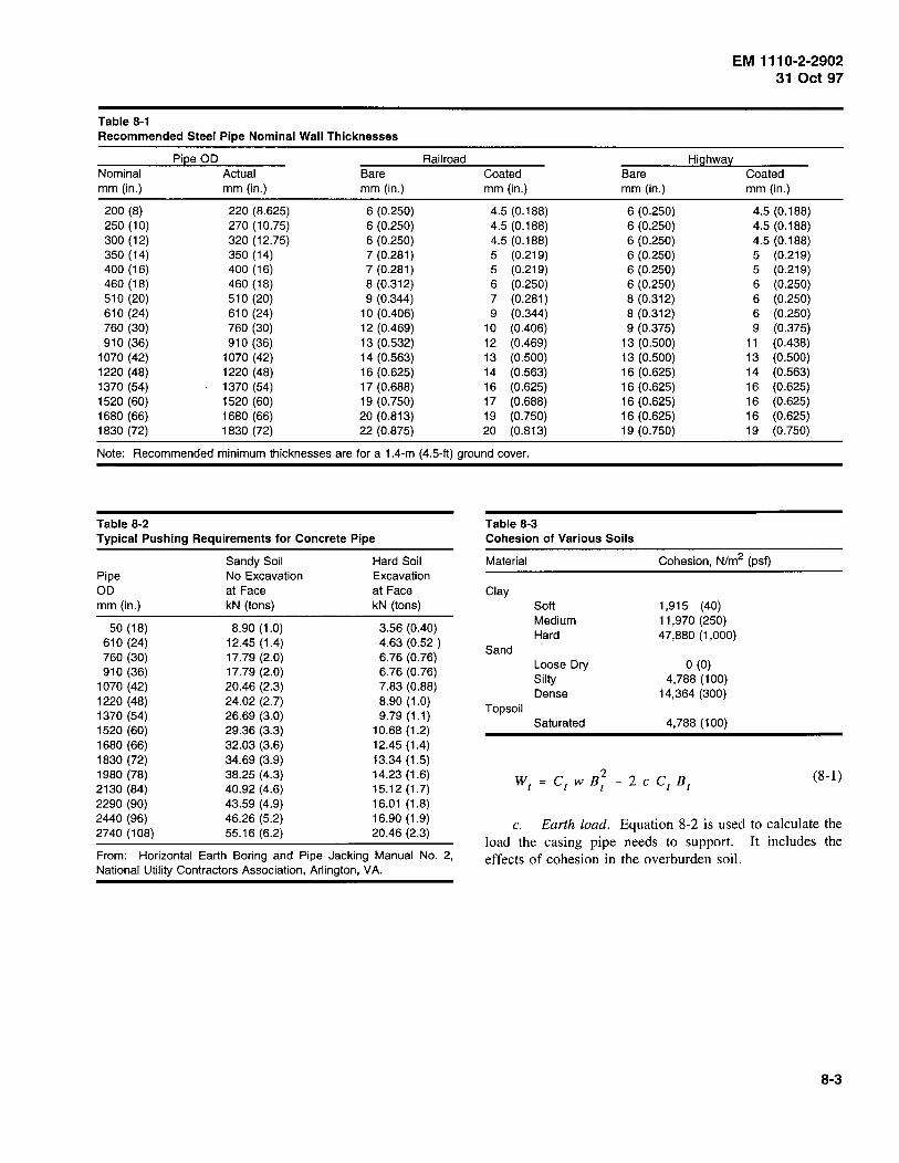
EM 1110-2-2902 31 Oct 97
Table 8-1 Recommended Steel Pipe Nominal Wall Thicknesses
Pi[!e OD Railroad Highway Nominal Actual Bare Coated Bare Coated mm (in.) mm(in.) mm(in.) mm(in.) mm(in.) mm(in.)
200 (8) 220 (8.625) 6 (0.250) 4.5 (0.188) 6 (0.250) 4.5 (0.188) 250 (10) 270 (10.75) 6 (0.250) 4.5 (0.188) 6 (0.250) 4.5 (0.188) 300 (12) 320 (12.75) 6 (0.250) 4.5 (0.188) 6 (0.250) 4.5 (0.188) 350 (14) 350 (14) 7(0.281) 5 (0.219) 6 (0.250) 5 (0.219) 400 (16) 400 (16) 7 (0.281) 5 (0.219) 6 (0.250) 5 (0.219) 460 (18) 460 (18) 8 (0.312) 6 (0.250) 6 (0.250) 6 (0.250) 510 (20) 510 (20) 9 (0.344) 7 (0.281) 8 (0.312) 6 (0.250) 610 (24) 610 (24) 10 (0.406) 9 (0.344) 8 (0.312) 6 (0.250) 760 (30) 760 (30) 12 (0.469) 10 (0.406) 9 (0.375) 9 (0.375) 910 (36) 910 (36) 13 (0.532) 12 (0.469) 13 (0.500) 11 (0.438)
1070 (42) 1070 (42) 14 (0.563) 13 (0.500) 13 (0.500) 13 (0.500) 1220 (48) 1220 (48) 16 (0.625) 14 (0.563) 16 (0.625) 14 (0.563) 1370 (54) 1370 (54) 17 (0.688) 16 (0.625) 16 (0.625) 16 (0.625) 1520 (60) 1520 (60) 19 (0.750) 17 (0.688) 16 (0.625) 16 (0.625) 1680 (66) 1680 (66) 20 (0.813) 19 (0.750) 16 (0.625) 16 (0.625) 1830 (72) 1830 (72) 22 (0.875) 20 (0.813) 19 (0.750) 19 (0.750)
Note: Recommended minimum thicknesses are for a 1.4-m (4.5-ft) ground cover.
Table 8-2 Typical Pushing Requirements for Concrete Pipe
Pipe OD mm (in.)
50 (18) 610 (24) 760 (30) 910 (36)
1070 (42) 1220 (48) 1370 (54) 1520 (60) 1680 (66) 1830 (72) 1980 (78) 2130 (84) 2290 (90) 2440 (96) 2740 (108)
Sandy Soil No Excavation at Face kN (tons)
8.90 (1.0) 12.45 (1.4) 17.79 (2.0) 17.79 (2.0) 20.46 (2.3) 24.02 (2.7) 26.69 (3.0) 29.36 (3.3) 32.03 (3.6) 34.69 (3.9) 38.25 (4.3) 40.92 (4.6) 43.59 (4.9) 46.26 (5.2) 55.16 (6.2)
Hard Soil Excavation at Face kN (tons)
3.56 (0.40) 4.63 (0.52) 6.76 (0.76) 6.76 (0.76) 7.83 (0.88) 8.90 (1.0) 9.79 (1.1)
10.68 (1.2) 12.45 (1.4) 13.34 (1.5) 14.23 (1.6) 15.12 (1.7) 16.01 (1.8) 16.90 (1.9) 20.46 (2.3)
From: Horizontal Earth Boring and Pipe Jacking Manual No. 2, National Utility Contractors Association, Arlington, VA.
Table 8-3 Cohesion of Various Soils
Material Cohesion, N/m2 (psf)
Clay Soft 1,915 (40) Medium 11,970 (250) Hard 47,880 (1 ,000)
Sand Loose Dry 0 (0) Silty 4,788 (100) Dense 14,364 (300)
Topsoil Saturated 4,788 (100)
(8-1)
c. Earth load. Equation 8-2 is used to calculate the load the casing pipe needs to support. It includes the effects of cohesion in the overburden soil.
8-3

EM 1110-2-2902 31 Oct 97
where
(8-2)
W1 = earth load under tunneled or jacked conditions, N/m (lbf/ft)
C1 = load coefficient for tunneled or jacked pipe
8-4
w
Bt
c
Kp '
H
= unit weight of soil, N/m3 (pcf)
= maximum width of bore excavation, m (ft)
= cohesion of soil above the excavation, N/m2
(psf) (Table 8-3)
= 0.165 (sand/gravel), 0.150 (saturated top soil), 0.130 (clay), and 0.110 (saturated clay)
= height of fill, m (ft)

Appendix A References
A-1. Required Publications
EM 1110-2-1603 Hydraulic Design of Spillways
EM 1110-2-1913 Design and Construction of Levees
EM 1110-2-2102 Waterstops and Other Joint Materials
EM 1110-2-2104 Strength Design for Reinforced-Concrete Hydraulic Structures
EM 1110-2-2400 Structural Design of Spillways and Outlet Works
EM 1110-2-2901 Tunnels and Shafts in Rock
Note: Specifications are grouped by issuing agency and then arranged in numerical order by specification designation.
American Association of State Highway & Transportation Officials (AASHTO) 1996 American Association of State Highway & Transportation Officials. 1996. Standard Specifications for Highway Bridges, Sixteenth Edition, Washington, DC.
American Association of State Highway & Transportation Officials (AASHTO) American Association of State Highway & Transportation Officials, M36/M36M, Standard Specification for Corrugated Steel Pipe, Metallic-Coated, for Sewers and Drains, Washington, DC.
American Association of State Highway & Transportation Officials (AASHTO) American Association of State Highway & Transportation Officials, Ml70/MJ70M, Standard Specification for Reinforced Concrete Culvert, Storm Drain, and Sewer Pipe, Washington, DC.
American Association of State Highway & Transportation Officials (AASHTO) American Association of State Highway & Transportation Officials, M 190, Standard Specification for Bituminous
EM 1110-2-2902 31 Oct 97
Coated Corrugated Metal Culvert Pipe and Pipe Aches, Washington, DC.
American Association of State Highway & Transportation Officials (AASHTO) American Association of State Highway & Transportation Officials, Ml96/MJ96M, Standard Specification for Corrugated Aluminum Pipe for Sewers and Drains, Washington, DC.
American Association of State Highway & Transportation Officials (AASHTO) American Association of State Highway & Transportation Officials, M206/M206M, Standard Specification for Reinforced Concrete Arch Culvert Storm Drain and Sewer Pipe, Washington, DC.
American Association of State Highway & Transportation Officials (AASHTO) American Association of State Highway & Transportation Officials, M207/M207M, Standard Specification for Reinforced Concrete Elliptical Culvert, Storm Drain and Sewer Pipe, Washington, DC.
American Association of State Highway & Transportation Officials (AASHTO) American Association of State Highway & Transportation Officials, M218, Standard Specification for Steel Sheet, Zinc-Coated (Galvanized) for Corrugated Steel Pipe, Washington, DC.
American Association of State Highway & Transportation Officials (AASHTO) American Association of State Highway & Transportation Officials, M242/M242M, Standard Specification for Reinforced Concrete D-Load Culvert, Storm Drain, and Sewer Pipe, Washington, DC.
American Association of State Highway & Transportation Officials (AASHTO) American Association of State Highway & Transportation Officials, M245/M245M, Interim Specification for Corrugated Steel Pipe, Polymer Precoated for Sewers and Drains, Washington, DC.
American Association of State Highway & Transportation Officials (AASHTO) American Association of State Highway & Transportation Officials, M246/M246M, Standard specifications for Steel Sheet, Metallic-Coated and Polymer Precoated for Corrugated Steel Pipe, Washington, DC.
A-1
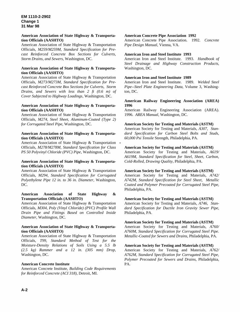
�
EM 1110-2-2902Change 131 Mar 98
A-2
American Association of State Highway & Transporta- American Concrete Pipe Association 1992tion Officials (AASHTO)American Association of State Highway & TransportationOfficials, M259/M259M, Standard Specification for Pre-cast Reinforced Concrete Box Sections for Culverts,Storm Drains, and Sewers, Washington, DC. American Iron and Steel Institute. 1993. Handbook of
American Association of State Highway & Transporta-tion Officials (AASHTO)American Association of State Highway & TransportationOfficials, M273/M273M, Standard Specification for Pre- American Iron and Steel Institute. 1989. Welded Steelcast Reinforced Concrete Box Sections for Culverts, Storm Pipe--Steel Plate Engineering Data, Volume 3, Washing-Drains, and Sewers with less than 2 ft (0.6 m) of ton, DC.Cover Subjected to Highway Loadings, Washington, DC.
American Association of State Highway & Transporta-tion Officials (AASHTO)American Association of State Highway & TransportationOfficials, M274, Steel Sheet, Aluminum-Coated (Type 2)for Corrugated Steel Pipe, Washington, DC. American Society for Testing and Materials (ASTM)
American Association of State Highway & Transporta-tion Officials (AASHTO)American Association of State Highway & TransportationOfficials, M278/M278M, Standard Specification for ClassPS 50 Polyvinyl Chloride (PVC) Pipe, Washington, DC.
American Association of State Highway & Transporta-tion Officials (AASHTO)American Association of State Highway & TransportationOfficials, M294, Standard Specification for Corrugated American Society for Testing and Materials, A742/Polyethylene Pipe 12 in. to 36 in. Diameter, Washington, A742M, Standard Specification for Steel Sheet, MetallicDC. Coated and Polymer Precoated for Corrugated Steel Pipe,
American Association of State Highway &Transportation Officials (AASHTO)American Association of State Highway & TransportationOfficials, M304, Poly (Vinyl Chloride) (PVC) Profile WallDrain Pipe and Fittings Based on Controlled InsideDiameter, Washington, DC.
American Association of State Highway & Transporta-tion Officials (AASHTO) A760M, Standard Specification for Corrugated Steel Pipe.American Association of State Highway & TransportationOfficials, T99, Standard Method of Test for theMoisture-Density Relations of Soils Using a 5.5 lb(2.5 kg) Rammer and a 12 in. (305 mm) Drop,Washington, DC.
American Concrete Institute PA.American Concrete Institute, Building Code Requirementsfor Reinforced Concrete (ACI 318), Detroit, MI.
American Concrete Pipe Association. 1992. ConcretePipe Design Manual, Vienna, VA.
American Iron and Steel Institute 1993
Steel Drainage and Highway Construction Products,Washington, DC.
American Iron and Steel Institute 1989
American Railway Engineering Association (AREA)1996American Railway Engineering Association (AREA).1996. AREA Manual, Washington, DC.
American Society for Testing and Materials, A307, Stan-dard Specification for Carbon Steel Bolts and Studs,60,000 Psi Tensile Strength, Philadelphia, PA.
American Society for Testing and Materials (ASTM)American Society for Testing and Materials, A619/A619M, Standard Specification for Steel, Sheet, Carbon,Cold-Rolled, Drawing Quality, Philadelphia, PA.
American Society for Testing and Materials (ASTM)
Philadelphia, PA.
American Society for Testing and Materials (ASTM)American Society for Testing and Materials, A746, Stan-dard Specification for Ductile Iron Gravity Sewer Pipe,Philadelphia, PA.
American Society for Testing and Materials (ASTM)American Society for Testing and Materials, A760/
Metallic-Coated for Sewers and Drains, Philadelphia, PA.
American Society for Testing and Materials (ASTM)American Society for Testing and Materials, A762/A762M, Standard Specification for Corrugated Steel Pipe,Polymer Precoated for Sewers and Drains, Philadelphia,
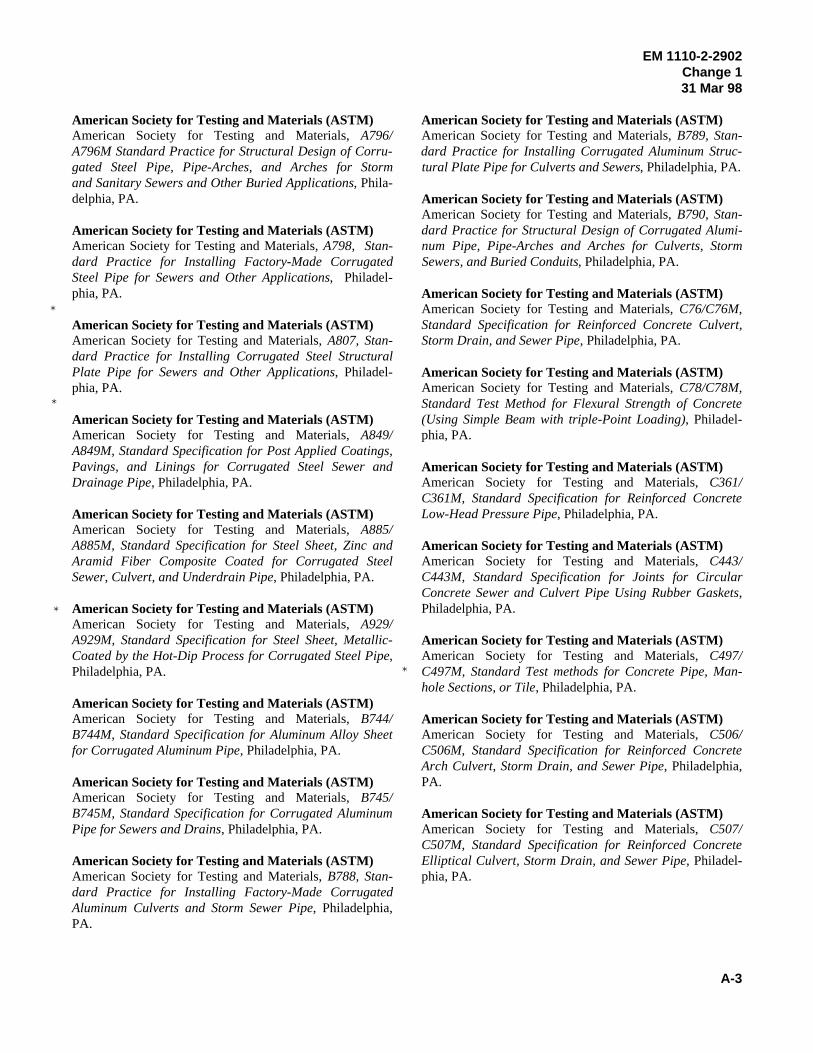
�
�
�
�
EM 1110-2-2902Change 131 Mar 98
A-3
American Society for Testing and Materials (ASTM) American Society for Testing and Materials (ASTM)American Society for Testing and Materials, A796/ American Society for Testing and Materials, B789, Stan-A796M Standard Practice for Structural Design of Corru- dard Practice for Installing Corrugated Aluminum Struc-gated Steel Pipe, Pipe-Arches, and Arches for Storm tural Plate Pipe for Culverts and Sewers, Philadelphia, PA.and Sanitary Sewers and Other Buried Applications, Phila-delphia, PA.
American Society for Testing and Materials (ASTM)American Society for Testing and Materials, A798, Stan- num Pipe, Pipe-Arches and Arches for Culverts, Stormdard Practice for Installing Factory-Made Corrugated Sewers, and Buried Conduits, Philadelphia, PA.Steel Pipe for Sewers and Other Applications, Philadel-phia, PA.
American Society for Testing and Materials (ASTM)American Society for Testing and Materials, A807, Stan- Storm Drain, and Sewer Pipe, Philadelphia, PA.dard Practice for Installing Corrugated Steel StructuralPlate Pipe for Sewers and Other Applications, Philadel-phia, PA.
American Society for Testing and Materials (ASTM)American Society for Testing and Materials, A849/ phia, PA.A849M, Standard Specification for Post Applied Coatings,Pavings, and Linings for Corrugated Steel Sewer andDrainage Pipe, Philadelphia, PA.
American Society for Testing and Materials (ASTM)American Society for Testing and Materials, A885/A885M, Standard Specification for Steel Sheet, Zinc andAramid Fiber Composite Coated for Corrugated SteelSewer, Culvert, and Underdrain Pipe, Philadelphia, PA.
American Society for Testing and Materials (ASTM)American Society for Testing and Materials, A929/A929M, Standard Specification for Steel Sheet, Metallic-Coated by the Hot-Dip Process for Corrugated Steel Pipe,Philadelphia, PA.
American Society for Testing and Materials (ASTM)American Society for Testing and Materials, B744/B744M, Standard Specification for Aluminum Alloy Sheetfor Corrugated Aluminum Pipe, Philadelphia, PA.
American Society for Testing and Materials (ASTM)American Society for Testing and Materials, B745/B745M, Standard Specification for Corrugated AluminumPipe for Sewers and Drains, Philadelphia, PA.
American Society for Testing and Materials (ASTM)American Society for Testing and Materials, B788, Stan- phia, PA.dard Practice for Installing Factory-Made CorrugatedAluminum Culverts and Storm Sewer Pipe, Philadelphia,PA.
American Society for Testing and Materials (ASTM)American Society for Testing and Materials, B790, Stan-dard Practice for Structural Design of Corrugated Alumi-
American Society for Testing and Materials (ASTM)American Society for Testing and Materials, C76/C76M,Standard Specification for Reinforced Concrete Culvert,
American Society for Testing and Materials (ASTM)American Society for Testing and Materials, C78/C78M,Standard Test Method for Flexural Strength of Concrete(Using Simple Beam with triple-Point Loading), Philadel-
American Society for Testing and Materials (ASTM)American Society for Testing and Materials, C361/C361M, Standard Specification for Reinforced ConcreteLow-Head Pressure Pipe, Philadelphia, PA.
American Society for Testing and Materials (ASTM)American Society for Testing and Materials, C443/C443M, Standard Specification for Joints for CircularConcrete Sewer and Culvert Pipe Using Rubber Gaskets,Philadelphia, PA.
American Society for Testing and Materials (ASTM)American Society for Testing and Materials, C497/C497M, Standard Test methods for Concrete Pipe, Man-hole Sections, or Tile, Philadelphia, PA.
American Society for Testing and Materials (ASTM)American Society for Testing and Materials, C506/C506M, Standard Specification for Reinforced ConcreteArch Culvert, Storm Drain, and Sewer Pipe, Philadelphia,PA.
American Society for Testing and Materials (ASTM)American Society for Testing and Materials, C507/C507M, Standard Specification for Reinforced ConcreteElliptical Culvert, Storm Drain, and Sewer Pipe, Philadel-

�
�
EM 1110-2-290231 Oct 97
A-4
American Society for Testing and Materials (ASTM) American Society for Testing and Materials (ASTM)American Society for Testing and Materials, C655/ American Society for Testing and Materials, C1214/C655M, Standard Specification for Reinforced Concrete C1214M, Testing Concrete Pipe Sewerlines by NegativeD-Load Culvert, Storm Drain, and Sewer Pipe, Philadel- Air Pressure, Philadelphia, PA.phia, PA.
American Society for Testing and Materials (ASTM)American Society for Testing and Materials, C789/ Method for Laboratory Compaction Characteristics ofC789M, Standard Specification for Precast Reinforced Soil Using Standard Effort (12,000 ft-lbf/ft3) (600 kN-Concrete Box Sections for Culverts, Storm Drains, and m/m3), Philadelphia, PA.Sewers, Philadelphia, PA.
American Society for Testing and Materials (ASTM)American Society for Testing and Materials, C850/ Standard Specification for Flexible Cellular Materials -C850M, Standard Specification for Precast Reinforced Sponge or Expanded Rubber, Philadelphia, PA.Concrete Box Sections for Culverts, Storm Drains, andSewers with less than 2 ft (0.6 m) of Cover subjected toHighway Loadings, Philadelphia, PA.
American Society for Testing and Materials (ASTM)American Society for Testing and Materials, C857/C857M, Standard Practice for Minimum Structural DesignLoading for Underground Precast Concrete Utility Struc-tures, Philadelphia, PA.
American Society for Testing and Materials (ASTM)American Society for Testing and Materials, C877/C877M, Standard Specification for External Sealing Bandsfor Noncircular Concrete Sewer, Storm Drain, and CulvertPipe, Philadelphia, PA.
American Society for Testing and Materials (ASTM)American Society for Testing and Materials, C900, Stan-dard Test Method for Pullout Strength of Hardened Con-crete, Philadelphia, PA.
American Society for Testing and Materials (ASTM)American Society for Testing and Materials, C924/ cation, Philadelphia, PA.C924M, Standard Practice for Testing Concrete PipeSewer Lines by Low-Pressure Air Test Method, Philadel-phia, PA.
American Society for Testing and Materials (ASTM)American Society for Testing and Materials, C969/ Loading, Philadelphia, PA.C969M, Standard Practice for Infiltration and ExfiltrationAcceptance Testing of Installed Precast Concrete PipeSewer Lines, Philadelphia, PA.
American Society for Testing and Materials (ASTM)American Society for Testing and Materials, C1103/C1103M, Standard Practice for Joint Acceptance Testingof Installed Precast Concrete Pipe sewer Lines, Philadel-phia, PA.
American Society for Testing and Materials (ASTM)American Society for Testing and Materials, D698, Test
American Society for Testing and Materials (ASTM)American Society for Testing and Materials, D1056,
American Society for Testing and Materials (ASTM)American Society for Testing and Materials, D1754,Standard Test Method for Effect of Heat and Air onAsphaltic Materials, Philadelphia, PA.
American Society for Testing and Materials (ASTM)American Society for Testing and Materials, D1784,Standard Specification for Rigid Poly(Vinyl) Chloride)(PVC) Compounds and Chlorinated PolyVinyl Chloride)CPVC) Compounds, Philadelphia, PA.
American Society for Testing and Materials (ASTM)American Society for Testing and Materials, D2262,Standard Test Method for Tearing Strength of WovenFabrics by the Tongue (Single Rip) Method (Constant Rateof Traverse Tensile Testing Machine), Philadelphia, PA.
American Society for Testing and Materials (ASTM)American Society for Testing and Materials, D2321,Standard Practice for Underground Installation of Ther-moplastic Pipe for Sewers and Other Gravity-Flow Appli-
American Society for Testing and Materials (ASTM)American Society for Testing and Materials, D2412,Standard Test Method for Determination of ExternalLoading Characteristics of Plastic Pipe by Parallel-Plate
American Society for Testing and Materials (ASTM)American Society for Testing and Materials, D2487-93,Standard Classification of Soils for Engineering Purposes(Unified Soil Classification System), Philadelphia, PA.

�
�
EM 1110-2-290231 Oct 97
A-5
American Society for Testing and Materials (ASTM) American Society for Testing and Materials (ASTM)American Society for Testing and Materials, D2680, American Society for Testing and Materials, D4254,Standard Specification for Acrylonitrile- Standard Test Method for Minimum Index Density andButadiene-Styrene (ABS) and Poly(Vinyl Chloride) (PVC) Unit Weight of Soils and Calculation of Relative Density,Composite Sewer Piping, Philadelphia, PA. Philadelphia, PA.
American Society for Testing and Materials (ASTM) American Society for Testing and Materials (ASTM)American Society for Testing and Materials, D3034, American Society for Testing and Materials, D4161,Standard Specification for Type PSM Poly(Vinyl Chloride) Standard Specification for 'Fiberglass' (Glass(PVC) Sewer Pipe and Fittings, Philadelphia, PA. Fiber-Reinforced Thermosetting Resin) Pipe Joints Using
American Society for Testing and Materials (ASTM)American Society for Testing and Materials, D3212,Standard Specification for Joint for Drain and Sewer American Society for Testing and Materials, F667, LargePlastic Pipes Using Flexible Elastomeric Seals, Philadel- Diameter Corrugated Polyethylene Tubing and Fittings,phia, PA. Philadelphia, PA.
American Society for Testing and Materials (ASTM) American Society for Testing and Materials (ASTM)American Society for Testing and Materials, D3262, American Society for Testing and Materials, F679,Standard Specification for 'Fiberglass' (Glass-Fiber- Standard Specification for Poly(Vinyl Chloride) (PVC)Reinforced Thermosetting Resin) Sewer Pipe, Philadel- Large-Diameter Plastic Gravity Sewer Pipe and Fittings,phia, PA. Philadelphia, PA.
American Society for Testing and Materials (ASTM) American Society for Testing and Materials (ASTM)American Society for Testing and Materials, D3350, American Society for Testing and Materials, F714,Standard Specification for Polyethylene Plastics Pipe and Standard Specification for Polyethylene (PE) Plastic PipeFittings Materials, Philadelphia, PA. (SDR-PR) Based on Outside Diameter, Philadelphia, PA.
American Society for Testing and Materials (ASTM) American Society for Testing and Materials (ASTM)American Society for Testing and Materials, D3550, American Society for Testing and Materials, F794,Standard Practice for Ring-Lines Barrel Sampling of Soils, Standard Specification for Poly(Vinyl) Chloride) (PVC)Philadelphia, PA. Profile Gravity Sewer Pipe and Fittings Based on
American Society for Testing and Materials (ASTM)American Society for Testing and Materials, D3839,Standard Practice for Underground Installation of 'Fiber- American Society for Testing and Materials, F894,glass' (Glass Fiber Reinforced Thermosetting Resin) Pipe, Standard Specification for Polyethylene (PE) LargePhiladelphia, PA. Diameter Profile Wall Sewer and Drain Pipe, Philadelphia,
American Society for Testing and Materials (ASTM)American Society for Testing and Materials, D3919,Standard Practice for Measuring Trace Elements in WaterAmerican Society for Testing and Materials, F949,by Graphite Furnace Atomic Absorption Spectrophotome- Standard Specification for Poly(Vinyl Chloride) (PVC)try, Philadelphia, PA. Corrugate Sewer Pipe with a Smooth Interior and Fittings,
American Society for Testing and Materials (ASTM)American Society for Testing and Materials, D4253,Standard Test Method for Maximum Index Density andAmerican Water Works Association. 1985. AWWA M11,Unit Weight of Soils Using a Vibratory Table, Philadelphia, Steel Pipe--A Guide for Design and Installation, Denver,PA. CO.
Flexible Elastomeric Seals, Philadelphia, PA.
American Society for Testing and Materials (ASTM)
Controlled Inside Diameter, Philadelphia, PA.
American Society for Testing and Materials (ASTM)
PA.
American Society for Testing and Materials (ASTM)
Philadelphia, PA.
American Water Works Association 1985
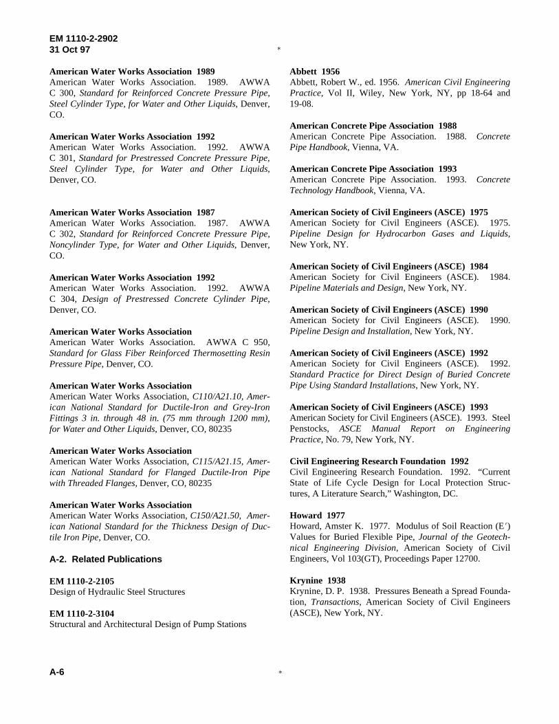
�
�
EM 1110-2-290231 Oct 97
A-6
American Water Works Association 1989 Abbett 1956American Water Works Association. 1989. AWWA Abbett, Robert W., ed. 1956. American Civil EngineeringC 300, Standard for Reinforced Concrete Pressure Pipe, Practice, Vol II, Wiley, New York, NY, pp 18-64 andSteel Cylinder Type, for Water and Other Liquids, Denver, 19-08.CO.
American Water Works Association 1992American Water Works Association. 1992. AWWA Pipe Handbook, Vienna, VA.C 301, Standard for Prestressed Concrete Pressure Pipe,Steel Cylinder Type, for Water and Other Liquids, American Concrete Pipe Association 1993Denver, CO.
American Water Works Association 1987American Water Works Association. 1987. AWWAC 302, Standard for Reinforced Concrete Pressure Pipe,Noncylinder Type, for Water and Other Liquids, Denver,CO.
American Water Works Association 1992American Water Works Association. 1992. AWWAC 304, Design of Prestressed Concrete Cylinder Pipe,Denver, CO.
American Water Works AssociationAmerican Water Works Association. AWWA C 950,Standard for Glass Fiber Reinforced Thermosetting ResinPressure Pipe, Denver, CO.
American Water Works AssociationAmerican Water Works Association, C110/A21.10, Amer-ican National Standard for Ductile-Iron and Grey-IronFittings 3 in. through 48 in. (75 mm through 1200 mm),for Water and Other Liquids, Denver, CO, 80235
American Water Works AssociationAmerican Water Works Association, C115/A21.15, Amer-ican National Standard for Flanged Ductile-Iron Pipewith Threaded Flanges, Denver, CO, 80235
American Water Works AssociationAmerican Water Works Association, C150/A21.50, Amer-ican National Standard for the Thickness Design of Duc-tile Iron Pipe, Denver, CO.
A-2. Related Publications
EM 1110-2-2105Design of Hydraulic Steel Structures
EM 1110-2-3104Structural and Architectural Design of Pump Stations
American Concrete Pipe Association 1988American Concrete Pipe Association. 1988. Concrete
American Concrete Pipe Association. 1993. ConcreteTechnology Handbook, Vienna, VA.
American Society of Civil Engineers (ASCE) 1975American Society for Civil Engineers (ASCE). 1975.Pipeline Design for Hydrocarbon Gases and Liquids,New York, NY.
American Society of Civil Engineers (ASCE) 1984American Society for Civil Engineers (ASCE). 1984.Pipeline Materials and Design, New York, NY.
American Society of Civil Engineers (ASCE) 1990American Society for Civil Engineers (ASCE). 1990.Pipeline Design and Installation, New York, NY.
American Society of Civil Engineers (ASCE) 1992American Society for Civil Engineers (ASCE). 1992.Standard Practice for Direct Design of Buried ConcretePipe Using Standard Installations, New York, NY.
American Society of Civil Engineers (ASCE) 1993American Society for Civil Engineers (ASCE). 1993. SteelPenstocks, ASCE Manual Report on EngineeringPractice, No. 79, New York, NY.
Civil Engineering Research Foundation 1992Civil Engineering Research Foundation. 1992. “CurrentState of Life Cycle Design for Local Protection Struc-tures, A Literature Search,” Washington, DC.
Howard 1977Howard, Amster K. 1977. Modulus of Soil Reaction (E1)Values for Buried Flexible Pipe, Journal of the Geotech-nical Engineering Division, American Society of CivilEngineers, Vol 103(GT), Proceedings Paper 12700.
Krynine 1938Krynine, D. P. 1938. Pressures Beneath a Spread Founda-tion, Transactions, American Society of Civil Engineers(ASCE), New York, NY.
�
�
EM 1110-2-290231 Oct 97
A-7
Leonards 1962 Rowe 1957Leonards, G. A., ed. 1962. Foundation Engineering, Rowe, R. R. 1957. Rigid Culverts Under High Overfills,McGraw-Hill, New York, NY. Transactions, American Society of Civil Engineers
Metcalf and Eddy 1928Metcalf, L. and Eddy, H. P. 1928. American SeweragePractice, Vol I, Second Edition, McGraw-Hill, New York, Spangler, M. G. 1948. Underground Conduits--AnNY. Appraisal of Modern Research, Transactions, American
National Utility Contractors AssociationNational Utility Contractors Association. Horizontal EarthBoring and Pipe Jacking Manual No. 2, Arlington, VA. Szechy, K. 1973. The Art of Tunneling, Hungarian Aca-
Newmark 1942Newmark, Nathan M. 1942. Influence Charts for Compu-tation of Stresses in Elastic Foundations. University of Water Pollution Control Federation. 1974. Design andIllinois Bulletin Series, No. 338, Urbana, IL. Construction of Sanitary and Storm Sewers, Manual of
Portland Cement Association 1975Portland Cement Association. 1975. Concrete Culvertsand Conduits, Skokie, IL.
Roark 1989Roark, R. J. 1989. Formulas for Stress and Strain,McGraw-Hill, New York, NY.
(ASCE), New York, NY.
Spangler 1948
Society of Civil Engineers (ASCE), New York, NY, p 316.
Szechy 1973
demy of Sciences, Budapest, Hungary.
Water Pollution Control Federation 1974
Practice, No. 9. (American Society of Civil Engineers(ASCE) Manual of Engineering Practice, No. 37.),New York, NY.
Appendix B Design Examples
Design examples for conduits, culverts, and pipes are presented in this appendix. Each equation in this manual is used in the order presented in its chapter. Once a variable is defined, that value is used throughout the remaining calculations. The design method for corrugated
EM 1110-2-2902 31 Oct 97
metal pipe from ASTM A 796 is included for Chapter 4. This method also applies to corrugated aluminum pipe using the ASTM B 790 method of design.
At the end of this appendix is a demonstration of a finite element method computer code used to analyze concrete rectangular and oblong shapes.
8-1
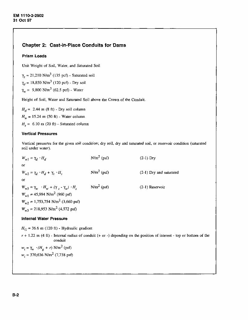
EM 1110-2-2902 31 Oct 97
B-2
Chapter 2: Cast-in-Place Conduits for Dams
Prism Loads
Unit Weight of Soil, Water, and Saturated Soil
'fs = 21,210 N/m3 (135 pet) - Saturated soil
'fd = 18,850 N/m3 (120 pet) - Dry soil
'fw = 9,800 N/m3 (62.5 pet) - Water
Height of Soil, Water and Saturated Soil above the Crown of the Conduit.
Hd = 2.44 m (8 ft) - Dry soil column
Hw = 15.24 m (50 ft) - Water column
Hs = 6.10 m (20 ft) - Saturated column
Vertical Pressures
Vertical pressures for the given soil condition; dry soil, dry and saturated soil, or reservoir condition (saturated soil under water).
or
or
W w3 = 'fw 'Hw + ('( s - 'fw) 'Hs
W wl = 45,994 N/m2 (960 psf)
Ww2 = 1,753,754 N/m2 (3,660 psf)
Ww3 = 218,953 N/m2 (4,572 psf)
Internal Water Pressure
Nlm2 (psf)
Nlm2 (psf)
Nlm2 (psf)
HG = 36.6 m (120 ft) - Hydraulic gradient
(2-1) Dry
(2-1) Dry and saturated
(2-1) Reservoir
r + 1.22 m (4ft)- Internal radius of conduit(+ or-) depending on the position of interest- top or bottom of the conduit
wi = 'Yw • (Hg + r) N/m2 (psf)
wi = 370,636 N/m2 (7,738 psf)
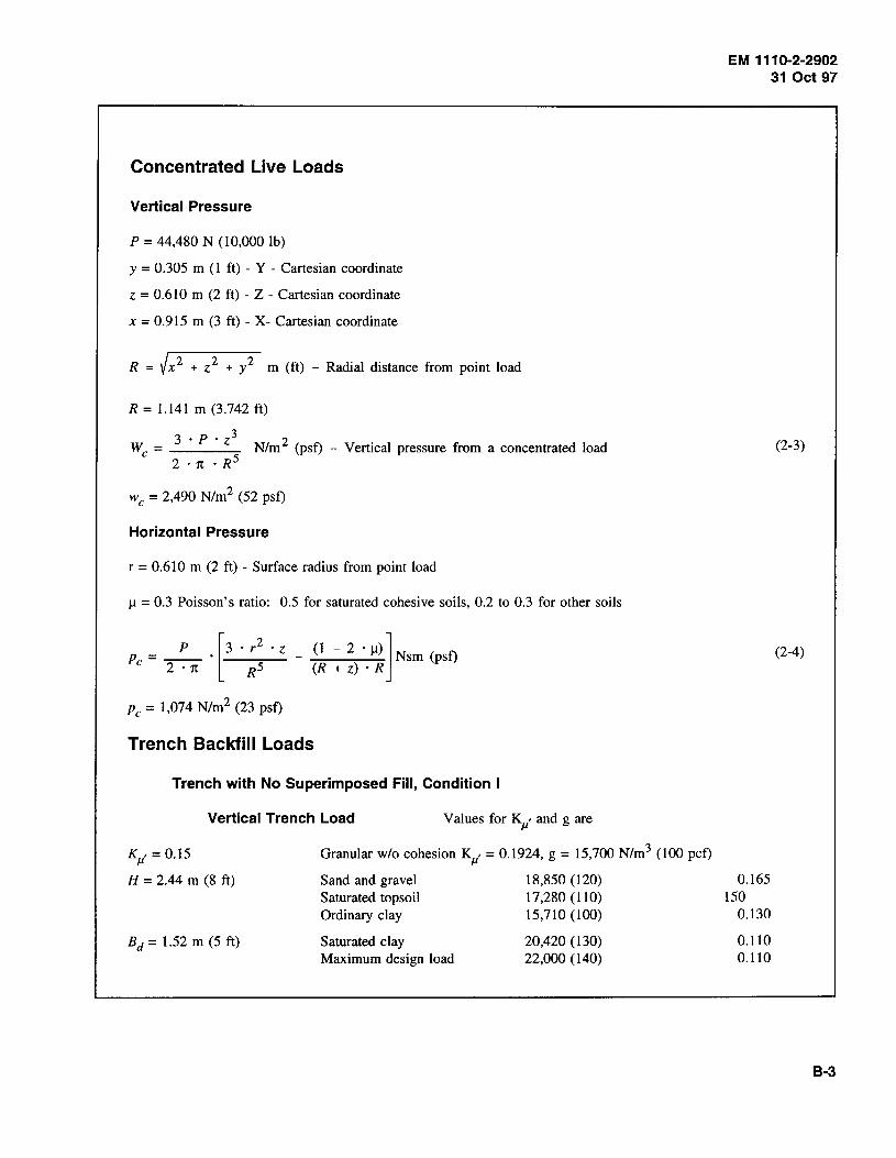
Concentrated Live Loads
Vertical Pressure
P = 44,480 N (10,000 lb)
y = 0.305 m (1 ft) - Y - Cartesian coordinate
z = 0.610 m (2ft) - Z - Cartesian coordinate
x = 0.915 m (3 ft) - X- Cartesian coordinate
R = V x2 + z2 + y 2 m (ft) - Radial distance from point load
R = 1.141 m (3.742 ft)
3 · P • z3 2 We = N/m (psf) - Vertical pressure from a concentrated load
2 · 1t • R5
w c = 2,490 N/m2 (52 psf)
Horizontal Pressure
r = 0.610 m (2 ft) - Surface radius from point load
11 = 0.3 Poisson's ratio: 0.5 for saturated cohesive soils, 0.2 to 0.3 for other soils
Pc = _P_ . [3 . r2 • z - (1 - 2 . ll)l Nsm (psf) 2 · 1t R5 (R + z) • R
Pc = 1,074 N/m2 (23 psf)
Trench Backfill Loads
Trench with No Superimposed Fill, Condition I
Vertical Trench Load Values for Kp' and g are
KJI, = 0.15
H = 2.44 m (8 ft)
Bd = 1.52 m (5 ft)
Granular w/o cohesion Kp' = 0.1924, g = 15,700 N/m3 (100 pcf)
Sand and gravel 18,850 (120) Saturated topsoil 17,280 (110) Ordinary clay 15,710 (100)
Saturated clay Maximum design load
20,420 (130) 22,000 (140)
EM 1110-2-2902 31 Oct 97
0.165 150
0.130
0.110 0.110
(2-3)
(2-4)
8-3
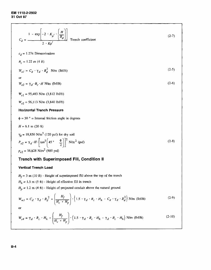
EM 1110-2-2902 31 Oct 97
B-4
-e{2 · K,, · (;.)] Trench coefficient
2 · KJ11
cd = 1.274 Dimensionless
Be= 1.22 m (4 ft)
or
We2 = Y d ·Be· H Nlm (lbf/ft)
Wei = 55,483 N/m (3,812 lbf/ft)
We2 = 56,113 N/m (3,840 lbf/ft)
Horizontal Trench Pressure
cj> = 30 o = Internal friction angle in degrees
H= 6.1 m (20ft)
Yct = 18,850 N/m3 (120 pcf) for dry soil
Pe2 = Yd·H·[tan2(45°- ~ )Y Nlm
2 (psf)
P e2 = 38,828 N/m2 (800 psf)
Trench with Superimposed Fill, Condition II
Vertical Trench Load
H1 = 3 m (10 ft) - Height of superimposed fill above the top of the trench
Hh = 1.5 m (5 ft) - Height of effective fill in trench
HP = 1.2 m (4 ft) - Height of projected conduit above the natural ground
W wJ = C d • y d • B / + [ : ) • ( 1.5 · y d • Be • H h - C d • y d • B J ) N/m (lbf/ft) He HP
or
(2-7)
(2-5)
(2-6)
(2-8)
(2-9)
(2-10)
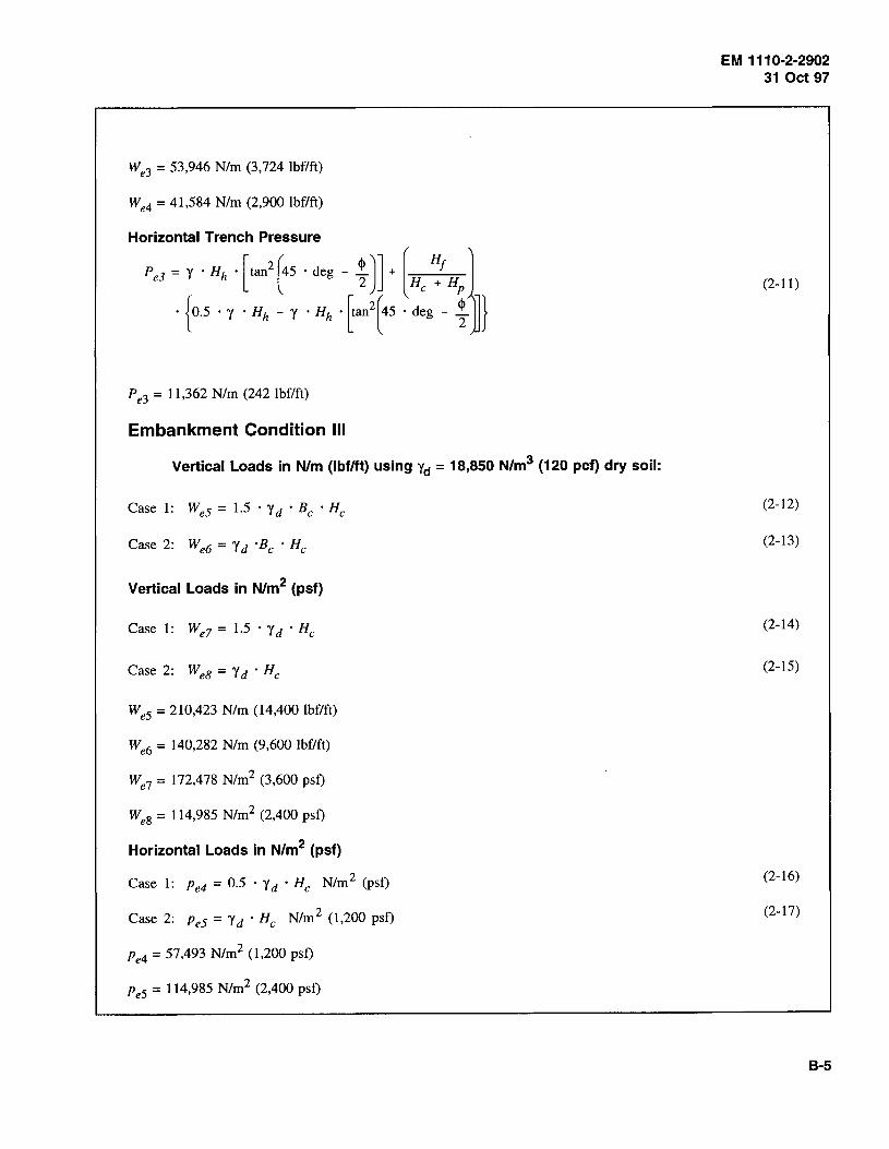
We3 = 53,946 N/m (3,724 lbf/ft)
We4 = 41,584 N/m (2,900 lbf/ft)
Horizontal Trench Pressure
PeJ = y · Hh • [tan2
(45 · deg - !)] + [ HI 1 2 He + HP
· { 0.5 · y · Hh - y · Hh • [tan2
(45 · deg - ; }
Pe3 = 11,362 N/m (242 lbf/ft)
Embankment Condition Ill
Vertical Loads in N/m (lbf/ft) using yd = 18,850 N/m3 (120 pcf) dry soil:
Case 1: Wes = 1.5 · y d • Be ·He
Vertical Loads in N/m2 (psf)
Case 1: We7 = 1.5 · y d • He
Case 2: WeB= Yd ·He
Wes = 210,423 N/m (14,400 lbf/ft)
We6 = 140,282 N/m (9,600 lbf/ft)
We? = 172,478 N/m2 (3,600 psf)
Wes = 114,985 N/m2 (2,400 psf)
Horizontal Loads in N/m2 (psf)
Case 1: Pe4 = 0.5 · y d ·He Nlm 2 (psf)
Case 2: Pes = y d • He Nlm 2 (1,200 psf)
P e4 = 57,493 N/m2 ( 1,200 psf)
peS = 114,985 N/m2 (2,400 psf)
EM 1110-2-2902 31 Oct 97
(2-11)
(2-12)
(2-13)
(2-14)
(2-15)
(2-16)
(2-17)
B-5
EM 111 0-2-2902 31 Oct 97
8-6
Notes on Loading Conditions for Embankments
Case 1: P/ we= 0.3 and ka = 0.50
Case 2: p /we = 1.00 and ka = 1.00
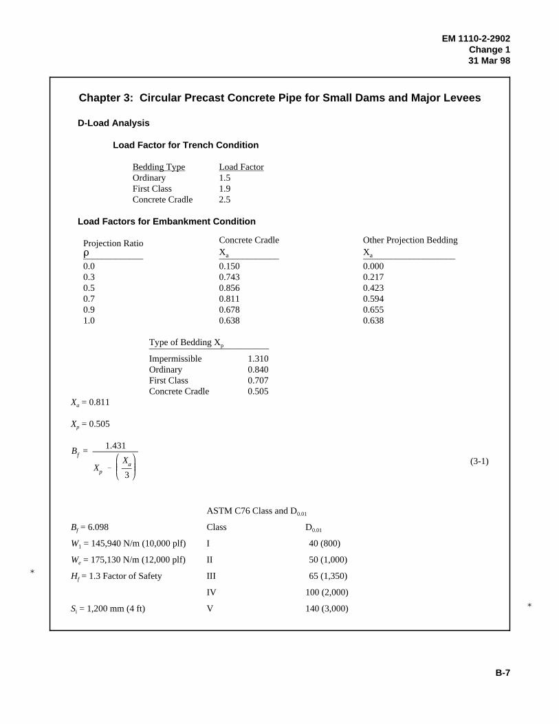
�
�
Bf =1.431
Xp
Xa
3
EM 1110-2-2902Change 131 Mar 98
B-7
(3-1)
Chapter 3: Circular Precast Concrete Pipe for Small Dams and Major Levees
D-Load Analysis
Load Factor for Trench Condition
Bedding Type Load FactorOrdinary 1.5First Class 1.9Concrete Cradle 2.5
Load Factors for Embankment Condition
Projection Ratio Concrete Cradle Other Projection Bedding' X X a a_____________ _____________ ____________________0.0 0.150 0.0000.3 0.743 0.2170.5 0.856 0.4230.7 0.811 0.5940.9 0.678 0.6551.0 0.638 0.638
Type of Bedding X p__________________________
Impermissible 1.310Ordinary 0.840First Class 0.707Concrete Cradle 0.505
X = 0.811a
X = 0.505p
ASTM C76 Class and D0.01
B = 6.098 Class Df 0.01
W = 145,940 N/m (10,000 plf) I 40 (800)1
W = 175,130 N/m (12,000 plf) II 50 (1,000)e
H = 1.3 Factor of Safety III 65 (1,350)f
IV 100 (2,000)
S = 1,200 mm (4 ft) V 140 (3,000)i
D��������
=W7
BI
#
HI
SL
=W7
(HI)
BI
(SL)
�
EM 1110-2-2902Change 131 Mar 98
B-8
(3-2)
D = 57 N/m/mm (1,172 plf/ft) ASTM C76M Class III0.01
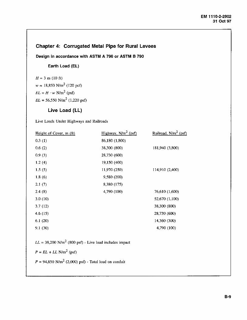
Chapter 4: Corrugated Metal Pipe for Rural Levees
Design in accordance with ASTM A 796 or ASTM B 790
Earth Load (EL)
H =3m (10ft)
w = 18,850 N/m2 (120 pet)
EL = H · w N!m2 (pst)
EL = 56,550 N/m2 (1,220 pst)
Live Load (LL)
Live Loads Under Highways and Railroads
Height of Cover, m (ft)
0.3 (1)
0.6 (2)
0.9 (3)
1.2 (4)
1.5 (5)
1.8 (6)
2.1 (7)
2.4 (8)
3.0 (10)
3.7 (12)
4.6 (15)
6.1 (20)
9.1 (30)
Highway, N/m2 (psf)
86,180 ( 1 ,800)
38,300 (800)
28,730 (600)
19,150 (400)
11,970 (250)
9,580 (200)
8,380 (175)
4,790 (100)
LL = 38,200 N/m2 (800 psf) - Live load includes impact
P = EL + LL N!m2 (pst)
P = 94,850 N/m2 (2,000) pst) - Total load on conduit
Railroad, N/m2 (psf)
181,940 (3,800)
114,910 (2,400)
76,610 (1,600)
52,670 (1,100)
38,300 (800)
28,730 (600)
14,360 (300)
4,790 (100)
EM 1110-2-2902 31 Oct 97
B-9
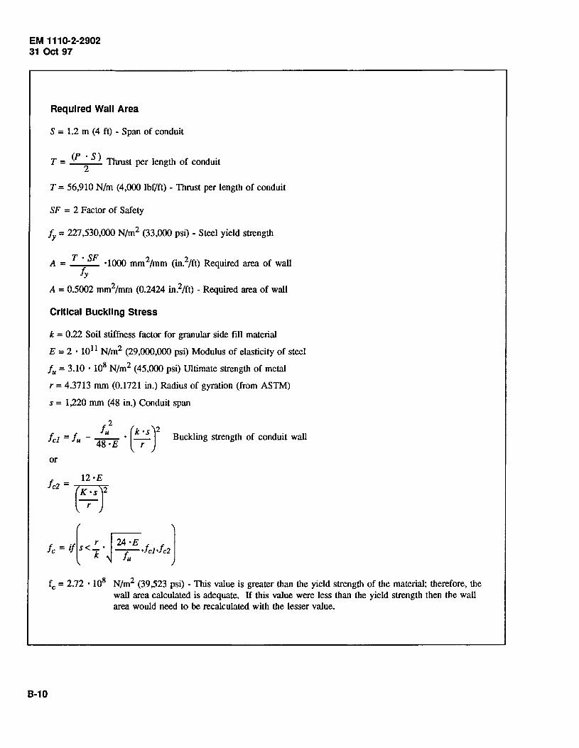
EM 1110-2-2902 31 Oct 97
Required Wall Area
S = 1.2 m (4 ft) - Span of conduit
(P • S) T = Thrust per length of conduit 2
T = 56,910 N/m (4,000 lbf/ft) - Thrust per length of conduit
SF = 2 Factor of Safety
fy = 227,530,000 N/m2 (33,000 psi) - Steel yield strength
A = T ·SF ·1000 mm2/mm (in.2/ft) Required area of wall fy
A= 0.5002 mm2/mm (0.2424 in.2/ft)- Required area of wall
Critical Buckling Stress
k = 0.22 Soil stiffness factor for granular side fill material
E = 2 · 1011 N/m2 (29,000,000 psi) Modulus of elasticity of steel
fu = 3.10 · 108 N/m2 (45,000 psi) Ultimate strength of metal
r = 4.3713 mm (0.1721 in.) Radius of gyration (from ASTM)
s = 1,220 mm (48 in.) Conduit span
fu2
(k •s)2 fc1 = fu - 48 • E • -r- Buckling strength of conduit wall
or
·( r ~ J fc = if S < k · ~ -r,;- ,fcJ ,fc2
B-10
fc = 2.72 • 108 N/m2 (39,523 psi) -This value is greater than the yield strength of the material; therefore, the wall area calculated is adequate. If this value were less than the yield strength then the wall area would need to be recalculated with the lesser value.
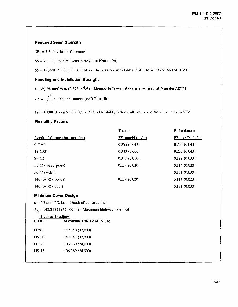
EM 1110-2-2902 31 Oct 97
Required Seam Strength
SF5
= 3 Safety factor for seams
SS = T · SF5
Required seam strength in N/m (lbf/ft)
SS = 170,730 N/m2 (12,000 lbf/ft)- Check values with tables in ASTM A 796 or ASTM B 790
Handling and Installation Strength
I- 39,198 mm4/mm (2.392 in.4/ft)- Moment in Inertia of the section selected from the ASTM
s2 6. FF = _ ·1,000,000 mm/N (FF/10 m.!lb) E·l
FF = 0.00019 mm/N (0.00003 in.!lbf) - Flexibility factor shall not exceed the value in the ASTM
Flexibility Factors
Depth of Corrugation, mm (in.)
6 (114)
13 (1/2)
25 (1)
50 (2 (round pipe))
50 (2 (arch))
140 (5-112 (round))
140 (5-1/2 (arch))
Minimum Cover Design
d = 13 mm (112 in.) -Depth of corrugations
Trench
FF, mm/N (in./lb)
0.255 (0.043)
0.343 (0.060)
0.343 (0.060)
0.114 (0.020)
0.114 (0.020)
AL = 142,340 N (32,000 lb)- Maximum highway axle load
Highway Loadings Class Maximum Axle Load, N (lb)
H 20
HS 20
H 15
HS 15
142,340 (32,000)
142,340 (32,000)
106,760 (24,000)
106,760 (24,000)
Embankment
FF, mm/N (in.lb)
0.255 (0.043)
0.255 (0.043)
0.188 (0.033)
0.114 (0.020)
0.171 (0.030)
0.114 (0.020)
0.171 (0.030)
B-11
EM 111 0-2-2902 31 Oct 97
. [ ~L. d S . [ ~L. d S ~L. d ]] Hmin = If 0.23 < --- , - If 0.45 > --- ,_, 0.55 · S · ---£·/ 8 E·l 4 E·l
Hmin = 0.3 m (1 ft) - minimum cover for highway loads and is never less than 0.3 m (1 ft)
Check the requirements for railroad and aircraft loads.
Pipe-Arch Bearing Design
Maximum height of fill over arch pipe assuming 191,520 N/m2 (2 tsf) bearing capacity for the soil
rc = 0.46 m (1.5 ft) - corner radius of pipe-arch
66.7 · rc Hmax = · 0.3048 m (Hma/0.3048 = ft) Maximum cover s Hmax = 7.79 m (25 ft)
B-12

Chapter 5: Culverts
EM 111 0·2-2902 31 Oct 97
Use the same design procedure as developed in Chapter 3 for precast pipe. Use the bedding load factors as defined in American Concrete Pipe Association Concrete Pipe Design Manual (1992).
Circular Concrete Culvert, Class B Bedding, Embankment Condition
CA B -:t - --=c==-N-_-x-q
CA = 1.431
eN= 0.101
X= 0.594
A= 0.33
p = 0.7
ce = 3
H= 8
Be= 4ft
E = 0.50
q = __ + EP ~ 0.33 AP(H ) Ce Be
q = 0·33<0·7) (2 + 0.5(0.7)) = 0.181 ~ 0.33
3
Bedding factor B1
B! = [0.707 - ~~~ (0.181)] = 2"387
D0_01 Calculation
WrHJ D -o.o1 - si Bf
Si =Be= 4ft
Hf= 1.0
B!= 2.387
Wr = 1.5 y Be Hh: y = 120 pcf
Hh = 8 + ± = 10 ft 2
Wr = 1.5(120)(4)(10) = 7200 lbf/ft
D = 7200 (1) = 754 _.!!:__ 0·
01 4 (2.387) ft/ft
Use Class I, C76 Pipe
(5-1)
(5-2)
B-13
EM 1110-2-2902 31 Oct 97
B-14
Chapter 6: Plastic Pipe for Other Applications
Pipe Stiffness
D = 0.250 m (10 in.)- Pipe diameter
R = D R = 0.125 m (5 in.) - Pipe radius 2
t = 8 mm (0.134 5 in.) - Wall thickness
EP = 3.03 · 109 N/m2 (440,000 psi) - Initial modulus of elasticity (plastic)
3 I= _r_ · 10-9 m4/m (in.4/in.) Moment of inertia
12
I = 4.27 · 10-8 m4/m (0.0026 in.4in.)
D2 FF = __ * 1000 < = 0.542 miN (95 in./lb)
E ·I
FF = 0.4834 miN (85 in.lb)
PS = E • I > = 98,946/D N/m/m (565/D lb/in./in.) 0.149 · R3
PS = 444,237 ~ 98•946
= 395,784 OK D
Deflection
DL = 2.5 Deflection lag factor for long-term prediction
K = 0.11 Bedding constant
E' = 6.89 · 106 N/m2 (1,000 psi) - Soil modulus
P = 69,000 N/m2 (10 psi) - Service pressure at the crown of the pipe
,1Y DL · K · P = ---------~ · 100 percent
D 0.149 . (PS) + 0.061 . (E 1)
,1Y - = 3.90% - Pipe deflection D
(6-1)
(6-2)
(6-3)

Wall Stress (Crushing)
PsT = 68,950 N/m2 (1,440 pst)- Short-term pressure at the crown of the conduit
PLT = 68,950 N/m2 (1,440 pst)- Long-term pressure at the crown of the conduit
fi = 3.03 · 109 N/m2 (440,000 psi) Initial tensile strength of the pipe material
fso = 1.09 · 109 N/m2 (158,400 psi) - 50-year tensile strength of the pipe material
D = 0.3 m (1 ft) - Diameter of pipe
PsT TsT = D • __ TsT = 10,343 N/m (720 lbf/ft) - Short-term wall thrust
2
PLT TLT = D • __ TLT = 10,343 N/m (720 lbf/ft) - Long-term wall thrust
2
A <=: 2 · _ + _ · 10 A = 25.8 mm lm (0.0124 in. /ft) (
TST TLT] 6 2 2
fi fso
Ring Buckling
H = 3 m (10 ft) - Height of soil above the crown of the pipe
Hw = 6 m (20 ft) - Height of water above the crown of the pipe
R = 0.3 m (12 in.) - Mean radius
hw B = 1 - 0.33 · _ Buoyancy factor B = 0.34
h
- Wall area
E = 9.65 · 108 N/m2 (140,000 psi) - 50-year Modulus of elasticity
Ms = 11.72 · 106 N/m2 (1 ,700 psi) - Soil modulus
A = 3,050 mm2/m (1.44 in.2/ft) - Wall area
I= 42,610 mm4/m (0.0026 in.4/in.) - Moment of inertia of the wall section
B · Ms · E ·I 2 N/m (fa* 12 (psi)) - Wall buckling stress
\ 0.149 · R3
0.77 · R fer= A
EM 1110-2-2902 31 Oct 97
(6-4)
(6-5)
(6-6)
(6-7)
B-15
EM 1110-2-2902 31 Oct 97
8-16
fa 6 2 fer =
2Fs = 2 fer = 7.6424 · 10 N/m (1,096 psi)
Hydrostatic Buckling
v = 0.39 Poisson's ration
K = 1.5 (10r 12 SI, 216 non-SI
Per= c[ (1
KEf ]· 0. 7 N/m 2 (psf) - Buckling stress - v2)R3
C = Ovality = 0. 7 for 4 percent deflection
Per= 1,886 N/m2 (37.3 psf) - Field stress or radial pressure from the water
Wall Strain Cracking
tmax = 6 mm (0.25 in.) - Thickness of pipe wall
D = 250 mm (10 in.)- Pipe diameter
L1Y = 3.9% Ratio of pipe deflection to pipe diameter D
[
0.03 . L1Y l · 1 (o.02 ~ ~) mrnlmm (in.r.n.)
- Wall strain < strain limit/2
£b = 0.003 < 0.0512 = 0.025 OK
(6-8)
(6-9)
Chapter 7: Ductile Iron Pipe and Steel Pipe for Other Applications
Earth Load Limited by:
Bending Stress
f = 3.31 · 108 N/m2 48,000 psi) - Design stress
t = 6 mm (0.25 in.) - Wall thickness
D = 250 mm (10 in.)- Pipe diameter
E = 165.5 · 109 N/m2 (24,000,000 psi) - Modulus of elasticity
E' = 3.45 · 106 N/m2 (500 psi) - Soil modulus DIPRA Type 4 bedding
Kb = 0.157 Bending moment coefficient
Kx = 0.096 Deflection coefficient
!J.x/D = 0.03 Deflection limit
f Pv= ---------------.------------------------------------,
+ 0.732
Pvl = 458,267 N/m2 (10,279) psf)
Deflection
Pv2 = 578,439 N/m2 (12,061 psf)
EM 111 0-2-2902 31 Oct 97
(7-1)
(7-2)
B-17

EM 1110-2-2902 31 Oct 97
B-18
Chapter 8: Pipe Jacking
Bt = 1.2 m (4 ft) - Diameter of pipe
w = 18,850 N/m3 (120 pcf) - Unit weight of soil
K11
= 0.130 Soil constant
H = 15 m (50 ft) - Height of soil
c = 4,790 N/m2 (100 psf) - Cohesion
exp[-2 · K,i · H ] Bt
Ct = 1 - ---=-----=---=-=-----l..---''-= Load coefficient 2 · K 1
ll
Ct = 0.8509 Load coefficient
2 Wt = Ct · w · Bt - 2 · c · C t · Bt Nlm (lbf/ft) - Earth load on pipe
wt = 13,314 N/m (953 lbf/ft)
(8-2)
(8-1)

EM 1110-2-2902 31 Oct 97
Rectangular Conduit rTrenchJ- Cast-In-Place
Vertical Pressure We = 18.9 (3)
= 57.6 kPa 0,200 psfJ
Per= 57.6 = 19.2 kPa ( 400 psfJ 3
Peb = 45 m 09.2) = 28.8 kPa 3.0 m (600 psfJ
Ws =Weight of Structure kN-m (plfJ
~ 0 Ordinary Damp Clay
""' Y ·189 kPo (120 pcf)
3m (/(Y (r)
BOX
Next calculate FEM/ s and distribute to des!gn sect! on. Use load factors from EM 1110-2-2104.
other Computer programs that can be used to analyze this sha{2ed culvert Include CAN DE (Culvert Analysfs DeslgnJ, CORTCUL (Des!gn or Invest! gat! on of Orthogonal Culverts)
Standard re!nforcement for rectanQular sect!ons Is !nc/uded !n ASTM C789 and CB50.
19.2 kPa I 575 kPa (/200 psfJ 19.2 kPo
BE (65J BE (65)
(~[]
2BE kPa (600 psfJ
( lws J 57.5 kPa 0200 psfJ Ws/3 m
D¢J 2BE kPo (600 psfJ
rvvs//Cf-(J'J
LOADING DIAGRAM
BE (65.v-:n!~-rr7-rr77'77"~~ BE (65J
9E (7 2J
122 (9.0)
122 (9.0)
122 (9.0)
MOMENT DIAGRAM kN-m (K-ft}
B-19
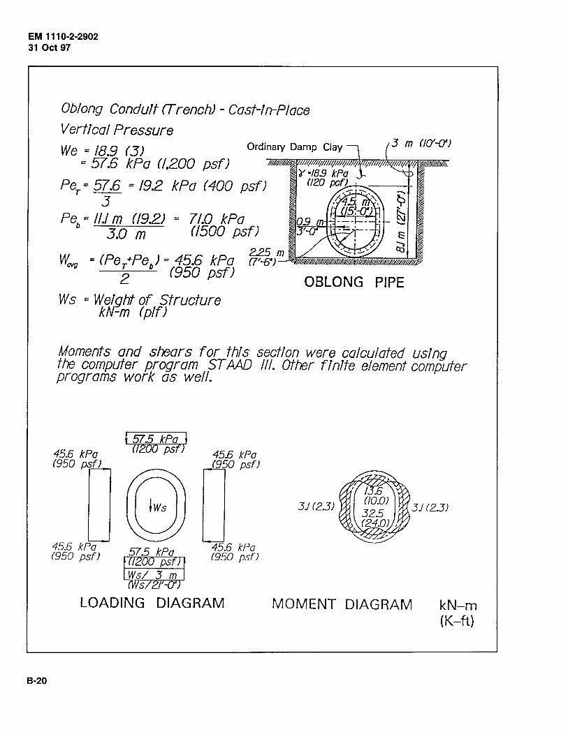
EM 111 0-2-2902 31 Oct 97
8-20
Oblong Conduit rTrenchJ- Cast-In-Place
Vertical Pressure
We = 18.9 (3) = 57.6 kPa (/,200 psfJ
Per= 57.6 = 19.2 kPa (400 psfJ 3
Peb = 1/J m (/9.2) = 71.0 kPa 3.0 m 0500 psfJ
Wa.'g = (Per+Peb) = 45.6 kPa 2 (950 psfJ
Ws = Weight of Structure kN-m (p/fJ
OBLONG PIPE
Moments and shears for this section were calculated using the computer program ST AAD Ill. Other finite element computer programs work as well.
45.6 kPa (950 pq_f)
45.6 kPa (950 psf)
l 515 kPa J (/2oo psn
45E kPa (950 psf)
45E kPo (950 psfJ
LOADING DIAGRAM
3J (23) 3) (23)
MOMENT DIAGRAM kN-m {K-ft)
Appendix C Evaluation and Inspection of Existing Systems
This appendix will be completed when data become available in the future. The outline below presents a list of key features that need to be considered when evaluating and inspecting existing systems.
C-1. Site Inspection
a. Surface settlement.
b. Surface water.
c. Dip in pavement.
d. Settlement of manholes or control structure.
C-2. Interior Inspection
a. Visual inspection.
b. Camera inspection.
c. Smoke testing.
d. Infiltration.
e. Exfiltration.
f Piping.
C-3. Failures
a. Leaking joints.
b. Separated joints.
c. Crushed pipe wall.
d. Perforated pipe wall.
e. Misaligned pipe sections.
f Root penetration of pipe.
g. Material deposition.
h. Change in loading condition.
EM 1110-2-2902 31 Oct 97
C-1
Appendix D Repair of Existing Systems
This appendix will be completed when data become available in the future. The outline below lists some methods to repair existing systems.
D-1. Pipe Replacement
D-2. Slip Lining
EM 1110-2-2902 31 Oct 97
D-3. In-Place Fracturing and Replacement
D-4. Concrete Relining
D-5. Plastic Relining and Grouting
D-6. Jacking Pipe
D-1
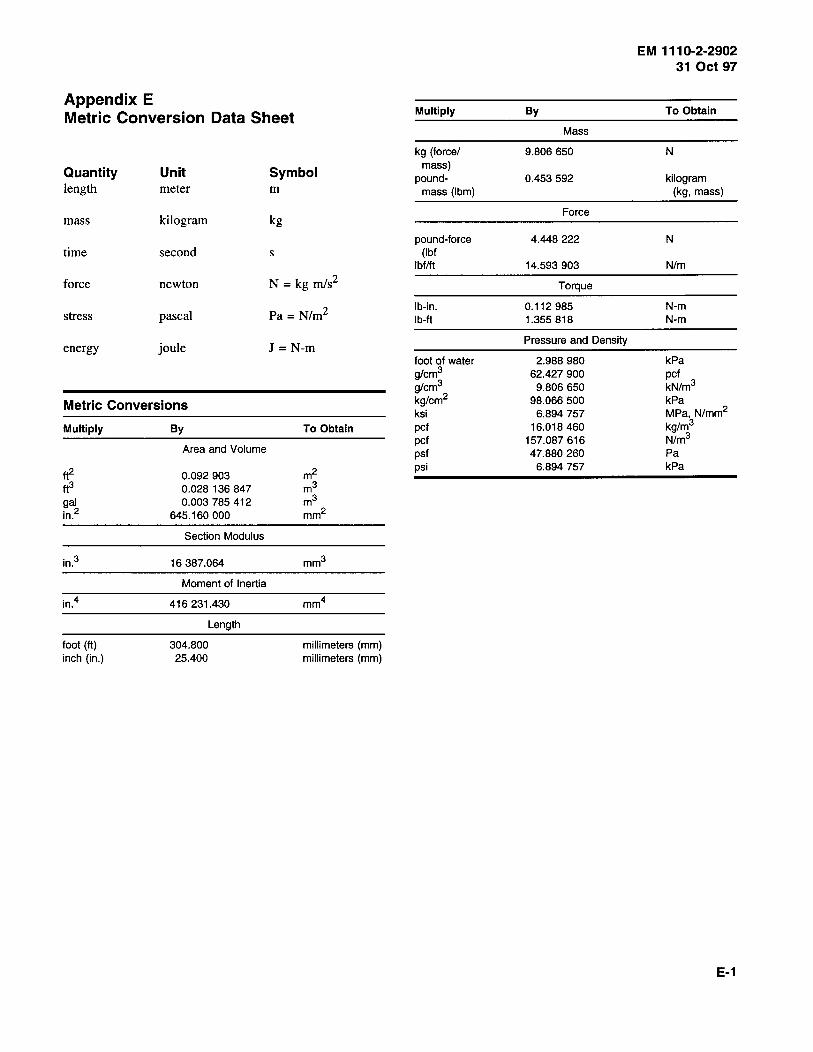
EM 1110-2-2902 31 Oct 97
Appendix E Metric Conversion Data Sheet Multiply By To Obtain
Mass
kg (force/ 9.806 650 N
Quantity Unit Symbol length meter m
mass) pound- 0.453 592 kilogram
mass (Ibm) (kg, mass)
mass kilogram kg Force
pound-force 4.448 222 N time second s (lbf
lbf/ft 14.593 903 N/m
force newton N =kg rnls2 Torque
stress pascal Pa = Nlm2 I b-in. 0.112 985 N-m lb-ft 1.355 818 N-m
energy joule J = N-m Pressure and Density
foot of water 2.988 980 kPa
Metric Conversions
g/cm3 62.427 900 pet g/cm3 9.806 650 kN/m3
kg/cm2 98.066 500 kPa ksi 6.894 757 MPa, N/mm2
Multiply By To Obtain
Area and Volume
pet 16.018 460 kg/m3
pet 157.087 616 N/m3
psf 47.880 260 Pa
tt2 0.092 903 m2 psi 6.894 757 kPa
tf3 0.028 136 847 m3
gal 0.003 785 412 m3
in.2 645.160 000 mm2
Section Modulus
in.3 16 387.064 mm3
Moment of Inertia
in.4 416 231.430 mm4
Length
foot (ft) 304.800 millimeters (mm) inch (in.) 25.400 millimeters (mm)
E-1