distribution independent of the pressure Replaces : 10.05 ...
36
Assembly instructions RE 64125-S/11.2010 Replaces : 10.05 English Directional control block with flow distribution independent of the pressure and available flow SX 14, SX 14 S
Transcript of distribution independent of the pressure Replaces : 10.05 ...

Assembly instructions
RE 64125-S/11.2010Replaces : 10.05English
Directional control block with flow distribution independent of the pressure and available flowSX 14, SX 14 S

The data specified above only serve to describe the product. No statements concerning a certain condition or suitability for a certain application can be derived from our information. The information given does not release the user from the obligation of own judgment and verification. It must be remembered that our products are subject to a natural process of wear and aging.
© This document, as well as the data, specifications and other information set forth in it, are the exclusive property of Bosch Rexroth AG. It may not be reproduced or given to third parties without its consent.
The title page shows an illustration of an example configuration. The delivered product may therefore deviate from the illustration.
The original operating instructions were written in French.
Subject to revision.

Contents1 Introduction .........................................................................................42 Safety instructions .............................................................................5
2.1 General safety instructions ............................................................52.2 Safety instructions in this document ..............................................5
3 Troubleshooting .................................................................................64 Fundamental rules ..............................................................................8
4.1 General information concerning control block connection .............85 Removal / installation of the SX 14, SX 14 S control block ............8
5.1 General recommendations .............................................................85.2 Removal of the SX 14, SX 14 S control block ................................95.3 Installation of the SX 14, SX 14 S control block .............................95.4 Starting, maximal pressure set up .................................................9
6 Inlet and outlet elements repair procedure ....................................106.1 LS pressure relief valve replacement ...........................................106.2 Flow regulator replacement .........................................................116.3 Flow divider replacement .............................................................126.4 Removal of the "closed center' or of the flushing valve or of the
"closed center .............................................................................136.5 Removal of the outlet element flushing valve ..............................146.6 Solenoid valve, "clamps" and shuttle valve removal (installed on
backhoe loader) ..........................................................................157 Distribution element repair procedure ...........................................16
7.1 Secondary valves replacement ....................................................167.2 Removal of spool with spring return .............................................187.3 Spool stroke measurement (3 position) .......................................217.4 hydraulic operation removal ........................................................227.5 Removal of mechanical detent system (pull function only) ..........237.6 Removal of electrical detent system (spool pushed or spool pulled)
257.7 Electrical controlled spool removal ..............................................287.8 Pressure compensator or check valve removal ...........................29
8 Control block Disassembly / Assembly ..........................................319 Precaution when replacing the spool lip seal ................................32
RE 64125-S/11.2010 | Type SX 14, SX 14 S Bosch Rexroth AG 3/34

Introduction1 This manual deals with the instructions relative to servicing and maintenance operations for the SX 14 and SX 14 S control blocks. For the inspections and servicing operations associated with the hydraulic system of the machine to which the block is connected, please consult the maintenance manual supplied by the equipment manufacturer.It is recommended that only qualified personnel perform the installation, connection and maintenance of this device, and that all operations be carried out in compliance with the technical standards in force and the cleanliness regulations specific to this type of installation.
To ensure maximum performance and safety during maintenance operations we advise you to READ THIS MANUAL THOROUGHLY.
All information, illustrations, instructions and characteristics contained in this document are based on the latest product information available at the time of publication. In its attempts to maintain a high-quality product, BOSCh REXROTh reserves the right to make design or technical modifications at any time and without prior notification.
Related documentsSX 14 and SX 14 S are system components.
Also follow the instructions for the other system components. •Also follow the instructions in the following manuals: •
System documentation from the system manufacturer –Service instruction manual RE64025 –Datasheet RE64125 –Spare parts manual RDEF64125-E –
4/34 Bosch Rexroth AG Type SX 14, SX 14 S | RE 64125-S/11.2010
Introduction

Safety instructions2
General safety instructions2.1 See service instruction manual RE64025.
Safety instructions in this document2.2 In this manual, there are safety instructions before the steps whenever there is a danger of personal injury or damage to the equipment. The measures described to avoid these hazards must be observed.Safety instructions are set out as follows :
Signal words/warning signsTable 1: Signal word/warning sign
Application
DANGERIndicates an imminently hazardous situation which, if not avoided, willcertainly result in serious injury.
WARNINGIndicates a potentially hazardous situation which, if not avoided, couldresult in serious injury.
NOTICEIndicates property or environment damages, practices not related to personal injury.
CAUTION Indicates a delicate operation.
Use or application hints.
DANGERType of risk!Description
precautions f
RE 64125-S/11.2010 | Type SX 14, SX 14 S Bosch Rexroth AG 5/34
Safety instructions

Troubleshooting3 CAUTION
BEFORE STARTING ANY PROCEDURES OF TROUBLE ShOOTING OR REMOVING ThE CONTROL BLOCk, INSPECT ThE GLOBAL MAChINE’S hYDRAULIC SYSTEM TO ELIMINATE ALL POSSIBLE MALFUNCTIONS NOT RELATED TO ThE SX 14 CONTROL BLOCk.
Abnormal operation of the actuators connected to the control blockTable 2:
Malfunction Probable cause Additional Checks Remedy
Lack of strength at all actuators
1 - LS pressure relief valve defective
Take a pressure measurement (see block specifications)
Replace LS pressure relief valve (see § 6.1)
2 - LS pressure relief valve out of adjustment
Make necessary adjustments (see § 5.4)
Lack of force on one actuator only
1 - Secondary pressure relief valve out of adjustment
Reset to original pressure (refer to block specifications). SX14S: change secondary pressure relief valve
2 - Secondary pressure relief valve blocked "open" (return to tank)
Replace secondary pressure relief valve (see § 7.1)
Lack of speed in the performance of a movement or all movements
SX 14 with "open center" on the inlet element (if so equipped) - Piston if the "open center" blocked in position P toward T
Replace housing + piston assembly (see § 8 and 6.4)
Movement performance slow
1 - Spool stroke incorrect Manual control: measure spool stroke (see § 7.3)Direct electrical control:- check solenoid resistance (R:2.5Ωà25°C)
If stroke is incorrect: replace housing + spool assembly (see § 8 and 7.2)If resistance is incorrect: replace solenoid (see § 7.7)
2 - hydraulic operator adjustable stopnut out of adjustment
Make necessary adjustments (see § 7.4)
3 - Individual compensator pressure blocked
Replace housing + pressure compensator assembly (see § 8 and 7.8)
Lack of load hold at work 1 - Load hold check valve failure Replace housing + valve assembly (see § 8 and 7.8)
Lack of load hold at neutral position or relief valve internal leak
1 - Excessive clearance between the housing and the spool
Replace housing + spool assembly (see § 8 and 7.2) or secondary pressure relief valve (see § 7.1)
Steering abnormally hard 1 - Flow divider adjustment problem
1 - Adjustment piston sliding freely
Replace control sub-system (see § 6.3)
2 - Adjustment piston blocked Replace housing + control system assembly (see § 8 and 6.3)
Steering response time abnormally long
Filter of the check piston’s flow divider is clogged
Replace the filter (see § 6.3)
Clamp operation malfunction (SX 14 installed on backhoe loader)
1 - Solenoid on the outlet element defective
Check solenoid resistance (R:7.6Ωà20°C)
If resistance is incorrect: replace the solenoid (see § 6.6)
2 - Shuttle valve malfunction on the outlet element
Replace shuttle valve (see § 6.6)
3 - 2-way valve defective Replace 2-way valve (see § 6.6)Simultaneous movement malfunction
1 - Blockage of the individual compensator orifice
Remove and clean individual compensator (see § 7.8)
2 - Individual pressure compensator blocked
Replace the housing + pressure compensator assembly (see § 7.8)
3 - LS line leakage Replace LS flow regulator (see § 6.2)
6/34 Bosch Rexroth AG Type SX 14, SX 14 S | RE 64125-S/11.2010
Troubleshooting

Abnormal machine operationTable 3:
Malfunction Probable cause Additional Checks Remedy
Engine remains under load after spools are returned to neutral
1 - flow regulator blocked Replace flow regulator (see § 6.2)2 - Flow regulator filter clogged Replace the filter (see § 6.2)
Abnormal control block operationTable 4:
Malfunction Probable cause Additional Checks Remedy
detent malfunction 1 - Mechanism defective Replace mechanical detent (see § 7.5)
2 - Solenoid defective Check solenoid resistance (for electrical detent) (R:16.5Ωat20°C)
If resistance is incorrect: Replace solenoid (see § 7.6)
Increase of force on controls or spool return defective
Control block assembly tie rods too tight
Check tightening torque Loosen and tighten to 42 ± 10% N.m. CAUTION
REMOVE CONTROL BLOCk FROM ITS FIXATION POINTS
Spool seals obsolete Replace spool seals (see § 7.2)
Visual defectsTable 5:
Malfunction Probable cause Additional Checks Remedy
Spool leaking oil Spool seals defective Replace spool seals (see § 7.2)Check the rubber boot condition
Oil leakage at pressure relief valves and plugs
Seals defective Remove pressure relief valve or plug and replace seals (see § 7.1)
Oil leakage between elements
Seals between elements defective Remove working sections and replace seals (see § 8)
Oil leaking from hydraulic operator housing
1 - Seal between housing and body defective
Replace seal (see § 7.4)
2 - seal of adjustable stop nut defective
Replace seal (see § 7.4)
Tongue control boot damaged
Replace boot (see § 7.2)
RE 64125-S/11.2010 | Type SX 14, SX 14 S Bosch Rexroth AG 7/34
Troubleshooting
Fundamental rules4
General information concerning control block 4.1 connection
When removing the block, all openings must be plugged immediately to prevent any contamination of the hydraulic system.When replacing the block, remove the plastic plugs from the openings and lines just before making the connections.Do not tighten connectors to a torque greater than that specified in the assembly instructions.Check the hydraulic installation’s oil quality and filtration capacity during all servicing/maintenance operations.The use of Teflon tape, hemp and joint filler is prohibited.hydraulic lines and connections must not be under any strain whatsoever.
Removal / installation of the SX 14, 5 SX 14 S control block
General recommendations5.1
NOTICEProperty damages risk
BEFORE REMOVING ThE SX 14 CONTROL BLOCk FROM ThE fMAChINE, ThE BLOCk AND ITS SURROUNDINGS MUST BE ThOROUGhLY CLEANED (DO NOT DIRECT ThE jET OF A PRESSURE WAShING UNIT DIRECTLY AT ThE UNIT).NO IMPURITIES MUST ENTER ThE hYDRAULIC SYSTEM. fPLASTIC PLUGS ARE TO BE FITTED ON LINES AND ORIFICES IMMEDIATELY FOLLOWING ThEIR REMOVAL.
DANGERWear protective clothing and use suitable equipment to prevent faccidents, particularly concerning the hydraulic fluid. Use the lifting eyes and suitable handling equipment. f Set all actuators connected to the machine in neutral position (on the fground, at lower limit ...) to avoid accidents which could result from uncontrolled movements of the equipment when the hydraulic system is disconnected. With the machine off, release the pressure remaining in the system fby manipulating all of the distribution spools. This is performed by moving the handle in all directions.
8/34 Bosch Rexroth AG Type SX 14, SX 14 S | RE 64125-S/11.2010
Fundamental rules

Removal of the SX 14, SX 14 S control block5.2 Install a vacuum pump on the tank to limit oil leakage when fconnections are removed.After disconnecting the lines from the block, immediately fit the sealing fplugs. Make sure to collect any possible oil leakage in a suitable receptacle.Unscrew the mounting screws and remove the control block. f
Installation of the SX 14, SX 14 S control block5.3 Contact faces must be perfectly clean. fCheck the evenness of support area on the machine (Tolerance: f0.5 mm).Check the condition of line connector seals. fClean the block if it has been in storage for a long period of time. fCorrectly place and secure the control block onto the machine with the fmounting screws.Connect the lines to the block as per the connecting diagram and ftighten to the torque specification (refer to the table in the Data sheet).Ensure that hoses are not twisted or rub. f
Once correctly installed, the unit can be placed into operation.
Starting, maximal pressure set up5.4 Decalibrate the LS pressure relief valve (19 mm open end spanner on fcounternut) before starting the machine,Maintain one of the control block spool valve in action before the linked fhydraulic receiver is at the end of stroke.
On the spool valve, the value of the secondary valve pressure must be greater than that of the ls pressure relief valve to adjust.
Adjust the maximum pressure measured in M using the LS pressure frelief valve (6 mm socket wrench).Tighten the counternut of the adjusting screw to the torque: f20 ± 10% N.m.
RE 64125-S/11.2010 | Type SX 14, SX 14 S Bosch Rexroth AG 9/34
Removal / installation of the SX 14, SX 14 S control block

Inlet and outlet elements repair 6 procedure
LS pressure relief valve replacement6.1
On the inlet element, unscrew the LS pressure relief valve (24 mm open end spanner).
Reassembly:
install the LS pressure relief valve on the inlet element, torque: 1. 45 ± 10% N.m.
set the LS pressure relief valve to the specified value (see § 5.4),2.
fit a new appropriate locking cover.3.
The control block does not need to be removed from the machine to perform this operation.
DANGEROil pressureMachine off:
place all of the machine’s actuators connected to the control block in fneutral position,release stored pressure by operating all the spools. f
NOTICEEnvironment damages risk
Install a vacuum pump on the tank to limit oil leakage during this foperation.Collect possible leaks with a suitable receptacle. f
10/34 Bosch Rexroth AG Type SX 14, SX 14 S | RE 64125-S/11.2010
Inlet and outlet elements repair procedure

Flow regulator replacement6.2
On the inlet or outlet element:
unscrew the LS pressure relief valve (see § 6.1),1.
unscrew the flow regulator (22 mm open end spanner).2.
Flow regulator filter replacement:Using pliers, extract the filter from the end of the flow regulator. Be careful not to damage the seal and the end of the flow regulator.
Reassemble the filter in reverse order. f
Reassembly:
install the flow regulator on the inlet or outlet element, torque: 1. 20 ± 10% N.m,
install the LS pressure relief valve (see § 6.1).2.
The control block does not need to be removed from the machine to perform this operation.
DANGEROil pressureMachine off :
place all of the machine’s actuators connected to the control block in fneutral position,release stored pressure by operating all the spools. f
NOTICEEnvironment damages risk
Install a vacuum pump on the tank to limit oil leakage during this foperation.Collect possible leaks with a suitable receptacle. f
RE 64125-S/11.2010 | Type SX 14, SX 14 S Bosch Rexroth AG 11/34
Inlet and outlet elements repair procedure

Flow divider replacement6.3
On the inlet element, unscrew the plug (12 mm socket wrench).
Remove:
the shim, •the stop, •the spring, •the piston assembly. •
Replace defective parts.
Reassembly:
replace the plug O-ring,1.
reassemble parts in reverse order,2.
torque for the plug: 100 ± 10% N.m.3.
The control block does not need to be removed from the machine to perform this operation.
DANGEROil pressureMachine off :
place all of the machine’s actuators connected to the control block in fneutral position,release stored pressure by operating all the spools. f
NOTICEEnvironment damages risk
Install a vacuum pump on the tank to limit oil leakage during this foperation.Collect possible leaks with a suitable receptacle. f
12/34 Bosch Rexroth AG Type SX 14, SX 14 S | RE 64125-S/11.2010
Inlet and outlet elements repair procedure

Removal of the "closed center' or of the 6.4 flushing valve or of the "closed center
On the inlet element, unscrew the flushing value plug (12 mm socket wrench).
Remove:
the spring (flushing valve or open center), •shims (flushing valve or open center), •the piston. •
Reassembly:
replace the plug O-ring,1.
reassemble parts in reverse order,2.
torque for the plug: 100 ± 10% N.m.3.
The control block does not need to be removed from the machine to perform this operation.
DANGEROil pressureMachine off :
place all of the machine’s actuators connected to the control block in fneutral position,release stored pressure by operating all the spools. f
NOTICEEnvironment damages risk
Install a vacuum pump on the tank to limit oil leakage during this foperation.Collect possible leaks with a suitable receptacle. f
RE 64125-S/11.2010 | Type SX 14, SX 14 S Bosch Rexroth AG 13/34
Inlet and outlet elements repair procedure

Removal of the outlet element flushing valve6.5
On the outlet element, unscrew the flushing valve plug.(12 mm socket wrench).
Remove:
the spring, •shims, •the piston. •
Reassembly:
replace the plug O-ring,1.
reassemble parts in reverse order,2.
torque for the plug: 100 ± 10% N.m.3.
The control block does not need to be removed from the machine to perform this operation.
DANGEROil pressureMachine off :
place all of the machine’s actuators connected to the control block in fneutral position,release stored pressure by operating all the spools. f
NOTICEEnvironment damages risk
Install a vacuum pump on the tank to limit oil leakage during this foperation.Collect possible leaks with a suitable receptacle. f
14/34 Bosch Rexroth AG Type SX 14, SX 14 S | RE 64125-S/11.2010
Inlet and outlet elements repair procedure

S6.6 olenoid valve, "clamps" and shuttle valve removal (installed on backhoe loader)
Solenoid replacementOn the outlet element, unscrew the knurled knob from the solenoid.Pull the solenoid off the stem of the 2-ways valve.
Reassembly:replace the 2 seals of the solenoid,1. torque for the knob: 3,5 ± 10% N.m.2.
2-ways valve replacementUnscrew the 2-ways valve (24 mm wrench).Replace solenoid + 2-ways valve assembly.
Reassembly: torque: 45 ± 10% N.m. f
Shuttle valve or selector removalOn the outlet element, unscrew the plug (8 mm socket wrench).Unscrew the upper seat (4 mm socket wrench).Remove the ball using a magnet.Unscrew the lower seat (4 mm socket wrench).Replace shuttle valve parts.Apply a droplet of Loctite 542 pneumatic/hydraulic sealant on the seats thread.
CAUTION
DO NOT PUT LOCTITE ON ThE BALL.
Reassembly: reassemble parts in reverse order.1. torque for the lower seat: 20 ± 10% N.m.2. torque for the upper seat: 20 ± 10% N.m.3. torque for the plug: 20 ± 10% N.m.4.
The control block does not need to be removed from the machine to perform this operation.
DANGEROil pressureMachine off :
place all of the machine’s actuators connected to the control block in fneutral position,release stored pressure by operating all the spools. f
NOTICEEnvironment damages risk
Install a vacuum pump on the tank to limit oil leakage during this foperation.Collect possible leaks with a suitable receptacle. f
RE 64125-S/11.2010 | Type SX 14, SX 14 S Bosch Rexroth AG 15/34
Inlet and outlet elements repair procedure

Distribution element repair 7 procedure
Secondary valves replacement7.1
Secondary valve replacement on a standard SX 14 element (relief valve or anti-cavitation check valve)On the distribution element in question, unscrew the secondary valve (24 mm open end spanner).
Replace the 3 valve seals or the pressure relief valve.
Reassembly:
if necessary, set the pressure relief valve to the specified value,1.
install the secondary pressure relief valve on the distribution element, 2.
torque for the secondary valve: 70 ± 10% N.m.3.
anti-cavitation check valve: fit a new appropriate locking cover.4.
The control block does not need to be removed from the machine to perform this operation.
DANGEROil pressureMachine off :
place all of the machine’s actuators connected to the control block in fneutral position,release stored pressure by operating all the spools. f
NOTICEEnvironment damages risk
Install a vacuum pump on the tank to limit oil leakage during this foperation.Collect possible leaks with a suitable receptacle. f
16/34 Bosch Rexroth AG Type SX 14, SX 14 S | RE 64125-S/11.2010
Distribution element repair procedure

Secondary valve replacement on a SX 14 S element (relief valve or anti-cavitation check valve)On the distribution element in question, unscrew the secondary valve (10 mm socket wrench).
Replace the valve seal or the pressure relief valve.
Reassembly: torque: 30-35 N.m. f
Plug replacement on a standard SX 14 elementOn the distribution element in question, unscrew the plug (8 mm socket wrench).
Replace the 3 plug seals or the plug.
Reassembly: torque: 70 ± 10% N.m. f
Plug replacement on a SX 14 S elementOn the distribution element in question, unscrew the plug (10 mm socket wrench).
Replace the plug o-ring or the plug.
Reassembly: torque: 30-35 N.m. f
O-ring
RE 64125-S/11.2010 | Type SX 14, SX 14 S Bosch Rexroth AG 17/34
Distribution element repair procedure

R7.2 emoval of spool with spring return
Tongue sideOn the distribution element in question, unscrew the 2 mounting screws (screwdriver Torx Tx30).
Remove:
mounting screws (L=12 mm), •the boot and its plate, •the second plate. •
Reassembly:
replace the lip seal, or replace the old spool seals (wiper ring + O-ring) 1. by a lip seal,
CAUTION
POSITION ThE METALLIC PART OF ThE LIP SEAL ON ThE OUTSIDE.ThE LIP SEAL MUST BE FITTED ON ThE END OF ThE SPOOL SO ThAT IT IS NOT DAMAGED ON ThE SPOOL GROOVES AND ITS TIGhTNESS PROPERTY DOES NOT DETERIORATE. (SEE § 9)LUBRIFICATE ThE LIP SEAL WITh CLEAN hYDRAULIC OIL AND SLIDE IT PERPENDICULARLY ONTO ThE SPOOL.
Use tool Rexroth-Ref. R9 08 250 793.
reassemble parts in reverse order,2.
torque for the 2 mounting screws: 10 ± 10% N.m.3.
The control block does not need to be removed from the machine to perform this operation.
DANGEROil pressureMachine off :
place all of the machine’s actuators connected to the control block in fneutral position,release stored pressure by operating all the spools. f
NOTICEEnvironment damages risk
Install a vacuum pump on the tank to limit oil leakage during this foperation.Collect possible leaks with a suitable receptacle. f
18/34 Bosch Rexroth AG Type SX 14, SX 14 S | RE 64125-S/11.2010
Distribution element repair procedure

Cover sideOn the distribution element in question, unscrew the 2 mounting screws (screwdriver Torx Tx30).
Remove the cover.
Remove the spool from the working section.
Use the spool clamp (Rexroth-Ref. R9 08 103 002) and a vuce to secure the spool.
CAUTION
IN ORDER TO AVOID DAMAGING ThE SPOOL, PLACE IT APPROXIMATELY 30 MM FROM ThE END OF ThE SPOOL (NEVER IN ThE CENTRE).
Beforehand,heatthespoolto200°Cinanovenor,failingthat,withaheat gun. Do not use fire.
AVERTISSEMENTHot spool!Danger of burns
Wear thick protective gloves when handling the hot spool. f
Remove the adapter (5 mm socket wrench).
Remove:
2 spring retainers, •the spring, •the plate, •the lip seal or old spool seals (wiper ring + O-ring). •
RE 64125-S/11.2010 | Type SX 14, SX 14 S Bosch Rexroth AG 19/34
Distribution element repair procedure

Reassembly:
replace the lip seal, or replace the old spool seals (wiper ring + O-ring) 1. by a lip seal.
CAUTION
POSITION ThE METALLIC PART OF ThE LIP SEAL ON ThE OUTSIDE.ThE LIP SEAL MUST BE FITTED ON ThE END OF ThE SPOOL SO ThAT IT IS NOT DAMAGED ON ThE SPOOL GROOVES AND ITS TIGhTNESS PROPERTY DOES NOT DETERIORATE. (SEE § 9)LUBRIFICATE ThE LIP SEAL WITh CLEAN hYDRAULIC OIL AND SLIDE IT PERPENDICULARLY ONTO ThE SPOOL.
Use tool Rexroth-Ref. R9 08 250 793.
grease the spring,2.
except of coating, apply a droplet of loctite 262 on the end of the spool 3. internal thread,
reassemble the return system parts in reverse order,4.
torque for the 2 mounting screws: 10 ± 10% N.m5.
CAUTION
WAIT FOR 8 hOURS BEFORE USING ThE MAChINE TO LET ThE LOCTITE 262 DRY COMPLETELY.
20/34 Bosch Rexroth AG Type SX 14, SX 14 S | RE 64125-S/11.2010
Distribution element repair procedure

Tongue replacement (if necessary)Beforehand,heatthespoolto200°Cinanovenor,failingthat,withaheat gun. Do not use fire.
CAUTION
DO NOT USE A WELDING TORCh TO hEAT ThE TONGUE AS SPOOL DEFORMATION MAY RESULT.
AVERTISSEMENTHot spool!Danger of burns
Wear thick protective gloves when handling the hot spool. f
Loosen the tongue with an open end spanner (8 mm open end spanner).
Reassembly:
except of coating, apply a droplet of loctite 262 on the end of the 1. tongue thread,
reassemble parts in reverse order,2.
torque for the tongue: 10 ± 10% N.m,3.
torque for the 2 mounting screws: 10 ± 10% N.m.4.
CAUTION
WAIT FOR 8 hOURS BEFORE USING ThE MAChINE TO LET ThE LOCTITE 262 DRY COMPLETELY.
Spool stroke measurement (3 position)7.3 Move the control lever of the element in question in all possible positions, and measure the corresponding spool stroke values at the tongue.
RE 64125-S/11.2010 | Type SX 14, SX 14 S Bosch Rexroth AG 21/34
Distribution element repair procedure

H7.4 ydraulic operation removal
Adjustable stop nut seal replacementUsing a vernier, measure before replacement the dimension y between the stopnut screw and the nut tip (see diagram below).This value y is to be thoroughly respected when reassembling to ensure an identical flow adjustment.
Remove the nut (Gaz: 22 mm open end spanner, UNF: 27 mm open end panner)
Reassembly:
replace the nut O-ring or replace the nut + stopnut screw assembly,1.
torque for the nut: 40 ± 10% N.m.2.
CAUTION
WhILE TIGhTNING ThE NUT, BLOCk ThE STOPNUT SCREW USING A 6 MM SOCkET WRENCh.
Hydraulic control housing removalRemove the 4 mounting screws (6 mm socket wrench).
Remove:
the cover, •the O-ring, •the spring, •the spring retainer. •
Reassembly:
replace the O-ring on the body,1.
reassemble parts in reverse order,2.
torque for the 4 mounting screws: 10 ± 10% N.m.3.
The control block does not need to be removed from the machine to perform this operation.
DANGEROil pressureMachine off :
place all of the machine’s actuators connected to the control block in fneutral position,release stored pressure by operating all the spools. f
NOTICEEnvironment damages risk
Install a vacuum pump on the tank to limit oil leakage during this foperation.Collect possible leaks with a suitable receptacle. f
22/34 Bosch Rexroth AG Type SX 14, SX 14 S | RE 64125-S/11.2010
Distribution element repair procedure

R7.5 emoval of mechanical detent system (pull function only)
Tongue side: see § 7.2
Cover sideUnscrew the 4 mounting screws (screwdriver Torx Tx30).
Remove the cover.
Remove the spool from the working section.
Use the spool clamp (Rexroth-Ref. R9 08 103 002) and a vuce to secure the spool.
CAUTION
IN ORDER TO AVOID DAMAGING ThE SPOOL, PLACE IT APPROXIMATELY 30 MM FROM ThE END OF ThE SPOOL (NEVER IN ThE CENTRE).
The control block does not need to be removed from the machine to perform this operation.
DANGEROil pressureMachine off :
place all of the machine’s actuators connected to the control block in fneutral position,release stored pressure by operating all the spools. f
NOTICEEnvironment damages risk
Install a vacuum pump on the tank to limit oil leakage during this foperation.Collect possible leaks with a suitable receptacle. f
RE 64125-S/11.2010 | Type SX 14, SX 14 S Bosch Rexroth AG 23/34
Distribution element repair procedure

Using a metal rod (min. length = 80 mm, Ø 6), push the central ball while extracting the detent bush.
CAUTION
MARk ThE ORIENTATION OF ThE DETENT BUSh FOR ThE REASSEMBLY.
Remove the balls and the spring.
Reassembly:
introduce the spring into the adapter,1.
place the 3 balls into the radial holes of the adapter and hold them with 2. a small amount of grease,
position the central ball against with the spring,3.
slip the detent bush onto a metal rod,4.
using the rod, press the central ball into the adapter, then slide the 5. detent bush onto the adapter, making sure that the 3 balls are still in place,
CAUTION
The orientation of the detent bush must be respected.
remove the metal rod, assembly is complete.6.
Exploded view of the mechanical detent system pull functionFigure 1:
24/34 Bosch Rexroth AG Type SX 14, SX 14 S | RE 64125-S/11.2010
Distribution element repair procedure

Reassembly of the system inside the distribution element:
replace the O-ring on the spacer,7.
replace the lip seal, or replace the old spool seals (wiper ring + O-ring) 8. by a lip seal on the spacer side and tongue side (see § 7.2).
CAUTION
POSITION ThE METALLIC PART OF ThE LIP SEAL ON ThE OUTSIDE.ThE LIP SEAL MUST BE FITTED ON ThE END OF ThE SPOOL SO ThAT IT IS NOT DAMAGED ON ThE SPOOL GROOVES AND ITS TIGhTNESS PROPERTY DOES NOT DETERIORATE. (SEE § 9)LUBRIFICATE ThE LIP SEAL WITh CLEAN hYDRAULIC OIL AND SLIDE IT PERPENDICULARLY ONTO ThE SPOOL.
Use tool Rexroth-Ref. R9 08 250 793.
torque for the 2 screws of the spacer: 10 ± 10% N.m. 9. torque for the 2 screws of the cover: 10 ± 10% N.m.
R7.6 emoval of electrical detent system (spool pushed or spool pulled)
Tongue side: see § 7.2
Cover sideRemove the 2 mounting screws (screwdriver Torx Tx30)
This operation can be performed independently of the solenoid replacement operation.Remove the control block from the machine for this operation, if necessary.
DANGEROil pressureMachine off :
place all of the machine’s actuators connected to the control block in fneutral position,release stored pressure by operating all the spools. f
NOTICEEnvironment damages risk
Install a vacuum pump on the tank to limit oil leakage during this foperation.Collect possible leaks with a suitable receptacle. f
RE 64125-S/11.2010 | Type SX 14, SX 14 S Bosch Rexroth AG 25/34
Distribution element repair procedure

Remove the spool from the distribution element.
Use the spool clamp (Rexroth-Ref. R9 08 103 002) and a vuce to secure the spool.
CAUTION
IN ORDER TO AVOID DAMAGING ThE SPOOL, PLACE IT APPROXIMATELY 30 MM FROM ThE END OF ThE SPOOL (NEVER IN ThE CENTRE).
Exploded view of the electrical detent system spool pulledFigure 2:
Exploded view of the electrical detent system spool pushedFigure 3:
26/34 Bosch Rexroth AG Type SX 14, SX 14 S | RE 64125-S/11.2010
Distribution element repair procedure

Spool pushed system: Remove the solenoid (10 mm socket wrench).
Spool pulled system: Remove the cover (19 mm open-end spanner).
To replace solenoid on spool pushed system, the control block does not need to be removed from the machine.
Remove:
the circlip, •the spring, •the armature, •the solenoid. •
Remove the adapter (6 mm open-end spanner)
Remove:
2 spring retainers, •the second spring, •the centering bush, •the O-ring. •
Reassembly:
replace the O-ring,1.
tongue side: replace the lip seal, or replace the old spool seals (wiper 2. ring + O-ring) by a lip seal on (see § 7.2),
reassemble parts in reverse order,3.
install a new solenoid if necessary,4.
torque for the adapter: 10 ± 10% N.m,5.
torque for the cover or of the solenoid: 20 ± 10% N.m,6.
torque for the 2 mounting screws: 10 ± 10% N.m,7.
RE 64125-S/11.2010 | Type SX 14, SX 14 S Bosch Rexroth AG 27/34
Distribution element repair procedure

E7.7 lectrical controlled spool removal
Solenoid control replacement
Remove the 2 mounting screws and the solenoid control (5 mm socket wrench).
Remove the mounting plate from the solenoid control.
Repeat the operation on the other side of the distribution element.
Reassembly:
replace the O-rings on the solenoid control and mounting plate,1.
reassemble parts in reverse order,2.
torque for the solenoid: 10 ± 10% N.m,3.
torque for the 2 mounting screws: 10 ± 10% N.m.4.
The control block does not need to be removed from the machine to perform this operation.
DANGEROil pressureMachine off :
place all of the machine’s actuators connected to the control block in fneutral position,release stored pressure by operating all the spools. f
NOTICEEnvironment damages risk
Install a vacuum pump on the tank to limit oil leakage during this foperation.Collect possible leaks with a suitable receptacle. f
28/34 Bosch Rexroth AG Type SX 14, SX 14 S | RE 64125-S/11.2010
Distribution element repair procedure

Pressure compensator or check valve removal7.8 Preliminary operationsRemove the control block from the machine (see § 5).Remove the distribution element in question (see § 8).
Individual pressure compensator removal on a standard SX 14 elementUnscrew the compensator plug (8 mm socket wrench).
Remove the compensator piston using a magnet to extract it from its bore.
NOTICERisk of infection when using magnetic tool
Clean parts to remove any attracted metal particle. fDo not use magnet for reassembly. f
Clean the piston’s nozzle with compressed air to remove all traces of pollution.
Check the condition of the bore in the distribution element body.
Reassembly:
replace the plug O-ring,1.
reassemble parts in reverse order,2.
torque for the plug: 60 ± 10% N.m.3.
Solid compensator piston
Dampened compensator piston
RE 64125-S/11.2010 | Type SX 14, SX 14 S Bosch Rexroth AG 29/34
Distribution element repair procedure
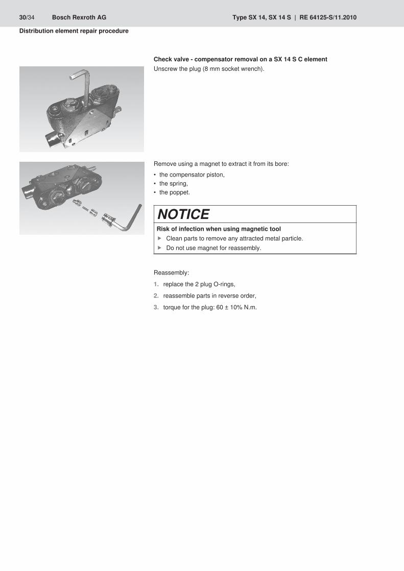
Check valve - compensator removal on a SX 14 S C elementUnscrew the plug (8 mm socket wrench).
Remove using a magnet to extract it from its bore:
the compensator piston, •the spring, •the poppet. •
NOTICERisk of infection when using magnetic tool
Clean parts to remove any attracted metal particle. fDo not use magnet for reassembly. f
Reassembly:
replace the 2 plug O-rings,1.
reassemble parts in reverse order,2.
torque for the plug: 60 ± 10% N.m.3.
30/34 Bosch Rexroth AG Type SX 14, SX 14 S | RE 64125-S/11.2010
Distribution element repair procedure
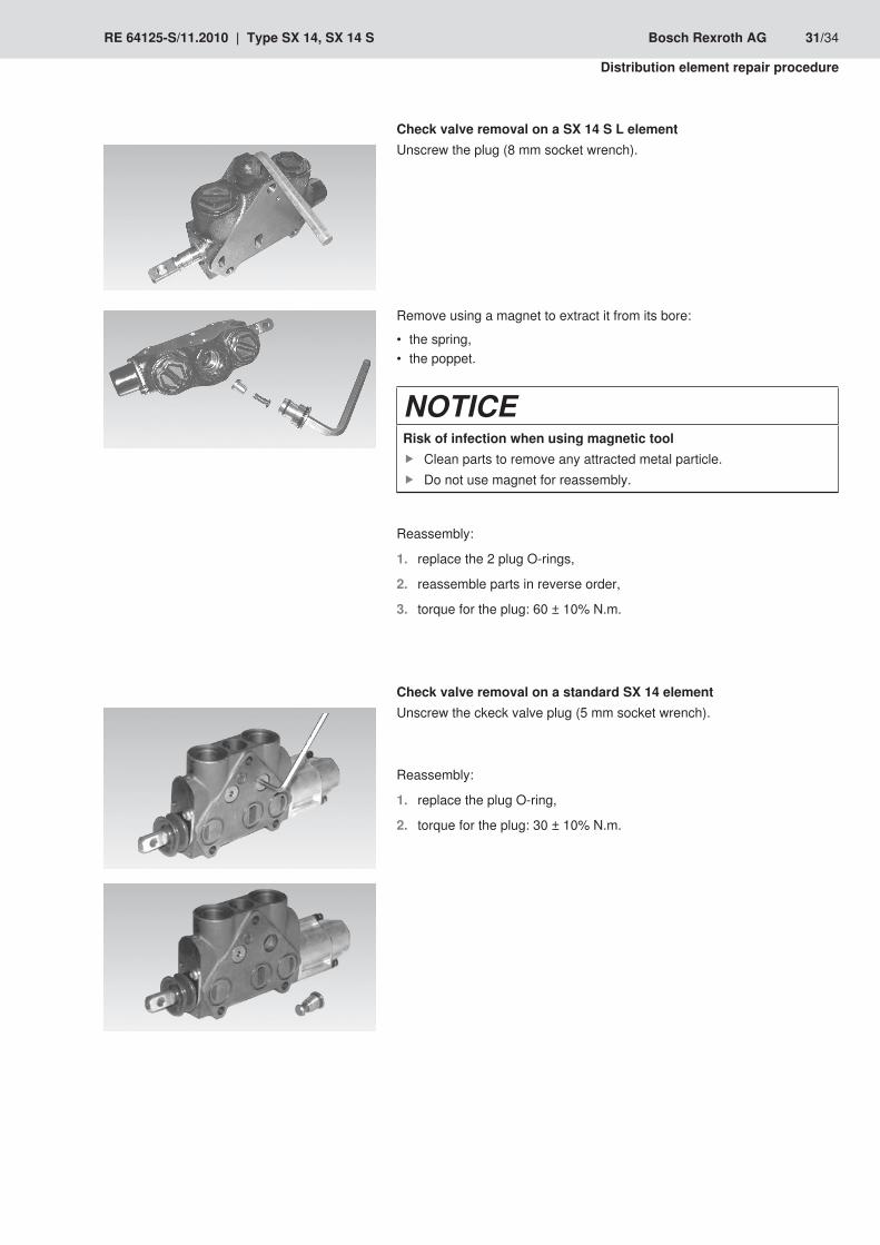
Check valve removal on a SX 14 S L elementUnscrew the plug (8 mm socket wrench).
Remove using a magnet to extract it from its bore:
the spring, •the poppet. •
NOTICERisk of infection when using magnetic tool
Clean parts to remove any attracted metal particle. fDo not use magnet for reassembly. f
Reassembly:
replace the 2 plug O-rings,1.
reassemble parts in reverse order,2.
torque for the plug: 60 ± 10% N.m.3.
Check valve removal on a standard SX 14 elementUnscrew the ckeck valve plug (5 mm socket wrench).
Reassembly:
replace the plug O-ring,1.
torque for the plug: 30 ± 10% N.m.2.
RE 64125-S/11.2010 | Type SX 14, SX 14 S Bosch Rexroth AG 31/34
Distribution element repair procedure
Control block Disassembly / 8 Assembly
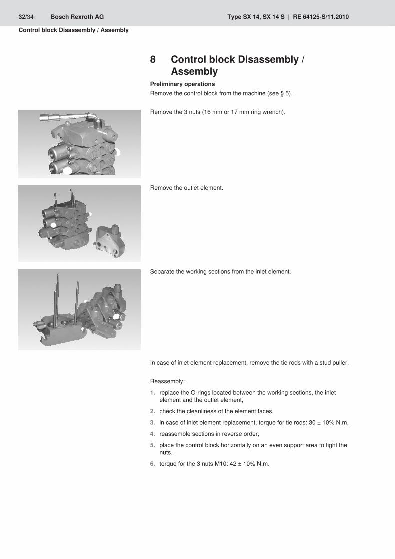
Preliminary operationsRemove the control block from the machine (see § 5).
Remove the 3 nuts (16 mm or 17 mm ring wrench).
Remove the outlet element.
Separate the working sections from the inlet element.
In case of inlet element replacement, remove the tie rods with a stud puller.
Reassembly:
replace the O-rings located between the working sections, the inlet 1. element and the outlet element,
check the cleanliness of the element faces,2.
in case of inlet element replacement, torque for tie rods: 30 ± 10% N.m,3.
reassemble sections in reverse order,4.
place the control block horizontally on an even support area to tight the 5. nuts,
torque for the 3 nuts M10: 42 ± 10% N.m.6.
32/34 Bosch Rexroth AG Type SX 14, SX 14 S | RE 64125-S/11.2010
Control block Disassembly / Assembly

Precaution when replacing the spool 9 lip seal
Place the spool in the working section.
Place tool Rexroth-Ref. R9 08 250 793 over the pool.
Lubrificate the lip seal with clean hydraulic oil and slide it perpendicularly onto the tool, positioning the metallic part of the lip seal on the outside.
The lip seal must be fitted on the end of the spool so that it is not damaged on the spool grooves and its tightness property does not deteriorate.
RE 64125-S/11.2010 | Type SX 14, SX 14 S Bosch Rexroth AG 33/34
Precaution when replacing the spool lip seal

34/34 Bosch Rexroth AG Type SX 14, SX 14 S | RE 64125-S/11.2010
Control block Disassembly / Assembly

Notes
RE 64125-S/11.2010 | Type SX 14, SX 14 S Bosch Rexroth AG

Subject to revision.Printed in FranceRE 64125-S/11.2010
Bosch Rexroth DSI S.A.S.BP 10191, bd Irène joliot-Curie69634 Vénissieux Cedex, FranceTelefon +33 (0) 4 78 78 52 52 Telefax +33 (0) 4 78 78 52 26www.boschrexroth.fr
Bosch Rexroth AGhydraulicsZum Eisengießer 197816 Lohr am Main, GermanyTél. +49 (0) 93 52 / 18-0Fax. +49 (0) 93 52 / 18-23 [email protected]