
Distributed Generation Interconnection Seminar - … DG Seminar Waltham... · Distributed...
95
Distributed Generation Interconnection Seminar July 20, 2017 National Grid 40 Sylvan Road, Waltham MA 02451 Auditorium
Transcript of Distributed Generation Interconnection Seminar - … DG Seminar Waltham... · Distributed...

Distributed Generation Interconnection
Seminar
July 20, 2017
National Grid
40 Sylvan Road, Waltham MA 02451
Auditorium

2
AGENDA
Co-Hosts

Agenda
3
8:30 Registration
9:00 Welcome, Opening Remarks – Will Kern
9:15 Interconnection Process & Timing – Alex Kuriakose
10:00 Interconnection Developments – Tim Roughan
10:40 Break
10:45 Interconnection Technical Session – Jeff Cahill
11:15 Post ISA Coordination – Hakob Mkrtchyan
11:30 First Bill Walkthrough – Colin Walker
11:50 Questions and Answer Session - National Grid Panel
12:00 Adjourn

4
Logistics & Introductions
Facilities
Emergency Exits
Restrooms
Designated smoking areas
Mobile Phones
Introductions
DOER / Mass CEC
MA Utilities
Guests

5
Safety Moment –
How to Spot and Survive a Riptide
Rip currents, also known as riptides, are long, narrow bands of water that can pull any objects caught in them away from shore and out to sea. Rip currents are dangerous, and it's best to learn how to identify and stay out of them. Keep your feet on the bottom as much as possible when swimming in surf conditions. Rip currents can occur in any ocean or lake where surf conditions (breaking waves) exist. Keeping your feet firmly on the lake or sea floor will help you to avoid being swept out to sea by a rip current. If, however, you get caught in a rip current, it's relatively easy to escape if you know what to do. 1. Remain calm if a rip current begins to pull you away from shore. A rip current will probably not pull you underwater; it will only pull you away from the shore.
2. Regain your footing if possible. If the current is relatively weak and you're in shallow water, you will probably be able to touch the bottom again and prevent yourself from being dragged out further. If you can't touch the bottom, do not struggle against the current. Conserve your energy for methodically swimming and staying afloat.
3. Call for help immediately. Get the attention of a lifeguard or of other beachgoers by waving your arms and yelling for help.

6
Safety Moment –
How to Spot and Survive a Riptide
4. Swim parallel to shore to get out of the current. Rather than swim against the
current toward shore, swim parallel to the shore. As you do so, the rip current will
carry you further away from shore, but remember, don't panic. Continue swimming
parallel to the shore until you are clear of the current. Float on your back or tread
water if you can't swim out of the current.
5. Swim toward the shore once you escape the current. When you are out of the
current swim diagonally toward shore and away from the current rather than
swimming straight back, to avoid swimming back into the rip current. You may be
some distance from shore at this point, so stop and float periodically if you need to
rest.

7
DOER Welcome Slide
DOER’s role in Distributed Generation:
o Assisting with incentives for clean energy
• Portfolio Standards (RPS/SRECs/APS)
• Net Metering
o Increasing awareness about policies
• Interconnection
• Rates
• System Planning / Service Quality
o Advising on new policies
• Streamlining Interconnection
• Hands-on assistance with challenging projects

Massachusetts Electric Utilities
8

9
DG Activity Trends - NE
Received 4,538 interconnection applications representing about 554.6 MW YTD June 2017
compared to 8,577 applications / 203.9 MW same period last year.
Small (<100kW) Interconnection application are triggering large studies because of the
aggregate generation on the circuit.
0
500
1,000
1,500
2,000
2,500
NE Applications Received
RI
MA
10
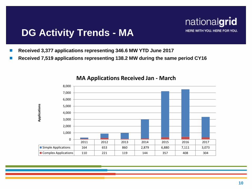
DG Activity Trends - MA
Received 3,377 applications representing 346.6 MW YTD June 2017
Received 7,519 applications representing 138.2 MW during the same period CY16
2011 2012 2013 2014 2015 2016 2017
Simple Applications 164 653 860 2,879 6,880 7,111 3,073
Complex Applications 110 221 119 144 357 408 304
0
1,000
2,000
3,000
4,000
5,000
6,000
7,000
8,000
Ap
plic
atio
ns
MA Applications Received Jan - March

11
DG Activity Trends - MA
Interconnected 2,981 applications representing 77.5 MW YTD June 2017
Interconnected 7,499 applications representing 90 MW during the same period CY16
2011 2012 2013 2014 2015 2016 2017
Simple Applications 141 419 870 1,453 4,900 7,286 2,799
Complex Applications 65 67 93 61 94 213 182
0
1,000
2,000
3,000
4,000
5,000
6,000
7,000
8,000
Ap
plic
atio
ns
MA Applications Interconnected Jan - June

11
ERV Basics
DG Interconnection Process
Customer Energy Integration
Alex Kuriakose

Interconnection
Discussion Agenda
The purpose of the Interconnection Process
Interconnection Process
Steps
Costs
Timetable
Common Missteps
Contacts and links for additional information
13
Importance of the Interconnection
Process
Safety of utility workers and general public
No adverse impact to power quality, in terms of:
Islanding
Transient Voltage Conditions
Noise and Harmonics
Frequency
Voltage Level
Machine Reactive Capability
Per tariff: customers cannot interconnect without an interconnection
agreement and approval. You proceed at your own risk if you don’t have utility
approval.
Billing implications
14
Interconnection Process Steps
Pre-Application
Simplified Application
Expedited/Standard Application
Impact Study and Detailed Study
Conditional Approval (to construct DG system)
National Grid Construction
Witness Test
Authorization to Interconnect
https://www.nationalgridus.com/masselectric/home/energyeff/4_interconnection-
process.asp
http://ngridustest/narragansett/home/energyeff/4_interconnection-process.asp
15

Pre-Application Report
Customer provides:
Contact and alternative contact Information
Facility Location (street address with cross streets,
including town, and a Google Map still picture and
GPS coordinates):
Generation type, size (AC kW), single or three
phase, service configuration:
Stand-alone (no on-site load, not including parasitic
load)?
If there is existing service at the Proposed Facility
site, provide: Interconnecting Customer Account
Number
Site minimum and maximum (if available) current or
proposed electric loads:
Is new service or service upgrade needed?
Utility provides:
• Circuit voltage, circuit number
• Whether single or three phase is available
near site; If single phase – distance from
three phase service;
• Aggregate of connected Facilities (kW) on
circuit;
• Aggregate of not yet connected (kW) on
circuit
• Whether the Interconnecting Customer is
served by an area network, a spot network, or
radial system;
• Identification of feeders within ¼ mile
• Other potential system constraints or critical
items
16

It Starts With The Application
A complete complex application package includes:
Complete application, signed and dated, with generator info
Pre-application (for projects over 500kW)
Application Fee ($300 minimum; $4.50 / kW – max of $7,500)
PE-Stamped 1-line diagram showing metering (relay settings if < 500kW)
Site Diagram showing electric service location, generator location, AC
Utility Disconnect, metering, access to metering and disconnect
Documentation problems “stop the clock” (Reference ESB756 as a guide to
avoid customer/contractor holds in the process).
Electronic documents preferred - however, mail first page of application with
application fee
17

18
Common Application Mistakes
Application not signed and dated
Name on application differs from name on utility account
Address of facility incorrect
Ownership of property not identified
Utility account or meter number not included or incorrect
Number of inverters not indicated
Landowner not identified
If new service, call Work Order Service group (800-375-7405): request service and write application “pending” account number and WR#.

19
Documentation Mistakes
Legal Info Document incorrectly represents intent of the parties
Third party ownership of generator
Legal Info Doc used to prepare Interconnection Service Agreements
1-line Diagram Errors:
Diagram doesn’t showing all equipment, including all metering
Transformer impedance data (% Z; X/R ratio) missing
Relay settings and islanding detection needed on larger projects
Site Plan Errors:
Doesn’t show location of metering, or incoming service, or transformer, or access road, or AC Utility Disconnect

Interconnection Costs
Application Fee
Studies: Supplemental Review, Impact Study, Detailed Study, Transmission
Not all projects will require Impact or Detailed Studies, or System Mods
System Modifications
Witness Test Fee(s)
Design, construction and installation of the Interconnection Facilities
20

Simplified Review Path
Single phase, UL Listed, inverter based systems 15kW (was previously 10
kW) or less on a single phase service on a radial feed
Three phase, UL List, inverter based systems 25kW or less on a three
phase service on a radial feed.
Listed (UL 1741.1) inverters, that comply with current IEEE 1547 standard,
or have nationally recognized test lab results
Additional 5 days for review if screen 5 is not met (project isn’t compatible
with existing service, e.g. loading on existing service transformer, etc.)
Does not apply to non-listed inverters or other generators (induction /
synchronous / asynchronous)
Does not apply to aggregate generation capacity of listed inverters that
exceed the above-mentioned limits
21
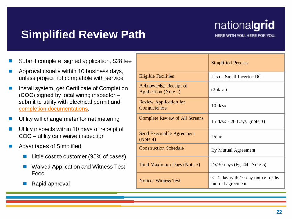
Simplified Review Path
Submit complete, signed application, $28 fee
Approval usually within 10 business days,
unless project not compatible with service
Install system, get Certificate of Completion
(COC) signed by local wiring inspector –
submit to utility with electrical permit and
completion documentations.
Utility will change meter for net metering
Utility inspects within 10 days of receipt of
COC – utility can waive inspection
Advantages of Simplified
Little cost to customer (95% of cases)
Waived Application and Witness Test
Fees
Rapid approval
Simplified Process
Eligible Facilities Listed Small Inverter DG
Acknowledge Receipt of
Application (Note 2) (3 days)
Review Application for
Completeness 10 days
Complete Review of All Screens 15 days - 20 Days (note 3)
Send Executable Agreement
(Note 4) Done
Construction Schedule By Mutual Agreement
Total Maximum Days (Note 5) 25/30 days (Pg. 44, Note 5)
Notice/ Witness Test < 1 day with 10 day notice or by
mutual agreement
22

Expedited Review Path
Single phase customers with listed single-phase inverter based systems
>15 kW on a radial feed
Three phase customers with listed three-phase inverter based systems
>25kW on a radial feed
Maximum size is based on review of screens
Does not Apply to:
Non-listed inverters or other generators (induction / synchronous /
asynchronous)
When aggregate generation capacity of listed inverters exceeds the
above-mentioned limits
23

Expedited Review Path
Often little or no System
Modifications required. If meter
only – usually no cost
Application fee plus any
Supplemental Review charges
up to 30 hours of engineering
time @ $150/hr. (if needed)
Relay control system must be
well defined to make
supplemental review easier.
Witness test fee of up to $300
plus travel may be required
Expedited
Eligible Facilities Listed Inverter DG
Acknowledge Receipt of Application
(Note 2) (3 days)
Review Application for
Completeness 10 days
Complete Review of All Screens 25 days
Complete Supplemental Review (if
needed) (Note 3) 20 days or Standard Process
Send Executable Agreement (Note 4) 10 days
Construction Schedule By Mutual Agreement
Total Maximum Days (Note 5) 45/65 days
(Note 5)
Notice/ Witness Test < 1 day with 10 day notice or by
mutual agreement
24

Supplemental Review
If any screens are not passed, the Company may provide a Supplemental Review
Agreement before providing an Interconnection Service Agreement
Key threshold is whether aggregate generation is less than 67% of minimum load on
the feeder. Other screens review voltage quality, reliability and safety to reduce the
potential need for impact studies.
Customer signs agreement and pays fee (max $4,500).
Supplemental Review may determine if any System Modifications are required. If no
Impact Study is needed an Interconnection Service Agreement will be sent to
customer detailing:
System Modifications, reasoning, and costs
Specifics on protection requirements
If Supplemental Review cannot determine requirements, an Impact Study
Agreement (or equal) will be sent to the customer. Shifts to standard process.
25

Standard Review Path
Applies to:
Non-listed inverters or other generators:
Induction, Synchronous, Asynchronous
Large-scale PV (500kW or greater)
Most CHP systems
*** Any project that requires more than 30 hours of
engineering time to identify System Modifications.
26
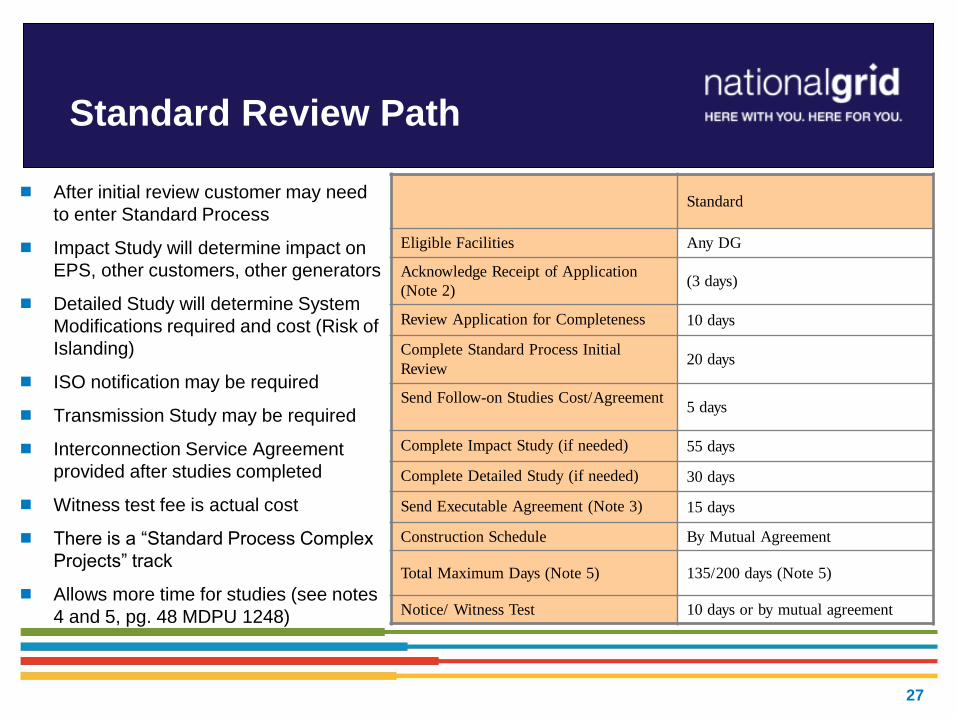
Standard Review Path
After initial review customer may need
to enter Standard Process
Impact Study will determine impact on
EPS, other customers, other generators
Detailed Study will determine System
Modifications required and cost (Risk of
Islanding)
ISO notification may be required
Transmission Study may be required
Interconnection Service Agreement
provided after studies completed
Witness test fee is actual cost
There is a “Standard Process Complex
Projects” track
Allows more time for studies (see notes
4 and 5, pg. 48 MDPU 1248)
Standard
Eligible Facilities Any DG
Acknowledge Receipt of Application
(Note 2) (3 days)
Review Application for Completeness 10 days
Complete Standard Process Initial
Review 20 days
Send Follow-on Studies Cost/Agreement 5 days
Complete Impact Study (if needed) 55 days
Complete Detailed Study (if needed) 30 days
Send Executable Agreement (Note 3) 15 days
Construction Schedule By Mutual Agreement
Total Maximum Days (Note 5) 135/200 days (Note 5)
Notice/ Witness Test 10 days or by mutual agreement
27

Interconnection Applications on non-dedicated circuits:
Largest wind application is 4.5 MVA on 13 kV class circuits
Largest Solar application is 6 MVA on 23 kV class circuits
Interconnection Applications on express(no load) circuits:
Largest wind application is 30 MVA on 34.5 kV class circuits
Largest Solar application is 14 MVA on 13 kV class circuits
Technical Issues: Limits on Distribution EPS - Radial
28

Timeline Compliance And “Holds”
Study “on hold” until company receives the requested info from customer
If an applicant requests additional time at or near a milestone, the Company will get
additional time to achieve that milestone
If an applicant requests a significant project change -- as determined by the
company - the applicant will be required to submit a new interconnection application
Recent examples – change of inverter could necessitate longer study and be
deemed moderate/ significant change (case by case basis)
At any time, an applicant may request a review of time-frame compliance by the
company, and the company must respond within ten business days
There is a process to remove customers from the “queue” if they don’t abide by the
timelines or extensions
Customer can request refund of application fee if the Company does not comply
with timeline(s)
29

Completion Documentation
PE-Stamped As-Built 1-line Diagrams – signed and dated
Certificate Of Completion – signed and dated
Commissioning Memo – signed and dated
Schedule Z – signed and dated with correct account numbers
Municipal Inspection – if needed – Inspector MUST call in
Net Metering Allocation (could be a Qualifying Facility instead)
(5) quality photos needed (with legible labels/plaques)
AC Utility Disconnect Current Limiting Device
Inverters / Generator Meter Socket
Pad-mount transformer
30

31
Behind the scenes at the utility…
Review and replacement of metering, modifications to billing
Modifications to protection systems as required (e.g. replace or install fusing, install switch, modify breaker/recloser set-points, transfer trip, etc.)
Larger generators require review by NEPOOL reliability committee and registration with ISO-NE
Adding generation asset to geographic information systems, maps, system one-lines, dispatch systems, etc.
Publish internal special operating guidelines for utility field personnel on larger generators.
Set up future testing for relay protection, meter calibration, insurance tracking, etc.

Many Stakeholders Involved
Utility • Application analyst – processes
application, agreements and assists with construction coordination
• Lead Engineer for reviews/studies • Relay Engineering • Distribution Planning • Distribution Dispatch • Distribution Design Engineering • Meter Operations • Meter Engineering • Meter Data Services • Relay Telecom Operations • Inspection team • Customer Service / Billing • Legal…
Interconnecting Customer
• Customer • Equipment vendor • Lead contractor • Electrician • Electrical Engineer (PE) • Relay Engineer • Relay testing firm • Legal
ISO-NE (If necessary)
32

Summary and Recommendations
Submit your interconnection application with National Grid early,
during conception phase before committing to buy no matter how
simple or small the DG might be.
You can always request general utility information about a specific
location from your utility
Large interconnection applications take longer to study
The Interconnection Tariff is a wealth of information
Time frames are standard working days and do not include delays
due to missing information or force majeure events
http://www9.nationalgridus.com/masselectric/business/energyeff/distributed_generation.asp
33

National Grid Contacts & Tariff
Links
34
Director Kevin Kelly | (978) 725-1325
Manager - NE John Kennedy | (401) 784-7221 William Kern | (781) 907-3023
Manager – DG Business Support (NE & NY) Vishal Ahirrao | (781) 907-3002
MA Vacancy (1) Alex Kuriakose | (781) 907-1643
Bob Moran | (508) 897-5656 Hakob Mkrtchyan | (781) 907-1516
Colin Sullivan | (781) 907-2937 Patrick Sullivan | (781) 907-1686
Eric Munzert | (781) 907-3833
Bassey Iro | (781) 907-2522 Melissa Drury | (781) 907-1472
Thomas Hurley | (781) 907-3145 Timothy Kounlavouth | (781) 907-3454
RI Diane Edwards | (401) 267-2061 Harmony Smith | (401) 267-6622
Patricia Matulaitis | (401) 784-7261
Screening Team Andy Garsils | (516) 545-4682 Nicholae Gari | (781) 907-2018
Joshua Dibia | (516) 545-4778
Analysts Chandra Bilsky | (401) 784-7174 Pamela Hill | (508) 860-6673
Jake Kailey | (781) 907-3729 Colin Walker | (781) 907-1489
Department Email: [email protected]
RI Website: https://www.nationalgridus.com/narragansett/home/energyeff/distributed_generation.asp
Customer Contact Center: 1-800-322-3223

35
Other MA Utility Contacts &
Tariff Links
• Eversource ~ NSTAR (Eastern Mass) DG team • Pyong Bruce Kim(Simplified)| (781) 441-8285 ([email protected]) • Complex| (781) 441-8196 • Email: [email protected] • https://www.eversource.com/Content/ema-c/residential/programs-services/customer-generation
• Eversource ~WM DG team (WMECo) • Phone: 413-787-1087 • Email: [email protected] • https://www.eversource.com/Content/wma/residential/programs-services/customer-generation
• Unitil • Phone: 603-773-6480 • Email: ([email protected]) • http://www.unitil.com/energy-for-residents/electric-information/distributed-energy-resources/renewable-energy-generation
36
Other Information Resources
• MA DG and Interconnection Website: http://sites.google.com/site/massdgic/
• Net Metering Basics: https://sites.google.com/site/massdgic/home/net-metering
• Interconnection Guide for Distributed Generation (Mass-CEC): http://files.masscec.com/uploads/attachments/InterconnectionGuideforDistributedGeneration.pdf

37
Interconnection Developments
Process & Recent Events
Regulatory ~ Tim Roughan

38
Net Metering in Massachusetts
December 2009 Net Metering Tariff, updated July 2012 by DPU.
DPU has issued clarifying orders in August 2012, and July 2013
Net Metering means the process of measuring the difference between electricity delivered by a Distribution Company and the electricity generated by a Class 1, Class II, or Class III Net Metering Facility and fed back to the Distribution Company.
Three Classes of Net Metering Facilities in Net Metering Tariff:
-- Class 1: Any generator up to 60 KW is eligible
-- Class 2: Agricultural, anaerobic digester, solar, or wind net metering facility over 60 KW but less than or equal to 1 MW (for municipal or government it’s “per unit”)
-- Class 3: Agricultural, anaerobic digester, solar, or wind net metering facility over 1 MW but less than or equal to 2 MW (for municipal or government it’s “per unit”)

39
Net Metering Credits
Credit the following charges
Class min max Type
Default
Service
kWH **
Dist-
ribution
kWH
Trans-
mission
kWH
Trans-
ition
kWH
I 0 60 KW Agricultural, Anaerobic
Digestion, Solar, Wind X X X X
I* 0 60 KW All Other
II >60 KW 1 MW Agricultural, Anaerobic
Digestion, Solar, Wind X X X X
III >1 MW 2 MW Agricultural, Anaerobic
Digestion, Solar, Wind X
Gov’t
only X X
Energy use is “netted” over the billing period, typically a month
- If there is net energy usage, Host Customer is billed for net purchases.
- If there is net energy sales, credit is export kWH times the following
- Credit is calculated on host customer’s rate
Notes: 1.) Class I* All Other (Non-Renewable) = Credited at average monthly clearing price set by ISO-NE.
2.) Default Service kWH ** = Fixed default service rate.
• Customer still responsible for customer charges and demand charges, even if net export
• Tariff allows credits to be allocated (with limitations)

40
Net Metering
Class 2 and Class 3 projects will need a production meter on generation.
Net Metering is limited to 7% of each utility’s peak MW for private and 8% of peak for public projects.
Contribution towards total is posted on each utility’s web site and updated monthly; also MASSACA website updated daily www.massaca.org
Cap data as
of 7/11/2017
Private: Available, Interconnected, Reserved and Pending Capacity (Values in kW)
Company Net Metering
Cap
Interconnect
ed (a)
Reserved Cap
Allocations (b)
Pending Cap
Allocations (c)
Capacity
Available Under
Cap (e)
Waiting List (d)
NGrid 359,170 225,017 132,915 23 1,215 3,242
NGrid-Nantucket
3,500 398 463 0 2,639 0
Public: Available, Interconnected, Reserved and Pending Capacity (Values in kW)
Company Net Metering
Cap
Interconnect
ed (a)
Reserved Cap
Allocations (b)
Pending Cap
Allocations (c)
Capacity
Available Under
Cap (e)
Waiting List (d)
NGrid 410,480 282,614 127,623 0 243 3,555
NGrid-Nantucket
4,000 100 0 0 3,900 0

41
Net Metering
All non-Simplified Applications for net metering must receive a Cap Allocation via the
System of Assurance (SoA) at http://www.MassACA.org.
Guidance on submitting an Application for Cap Allocation is available at:
http://www.massaca.org/help.asp,
via the [email protected] email,
or the MassACA Helpline (877) 357-9030
Need to determine whether project is a “Public” or a “Private” Facility
Public: Host Customer is certified as a Municipality or Other Governmental Entity by
the DPU and has Class II or Class III Facility. Host Customer allocates to only
customers who are certified Public. Ten MW limit per entity in Massachusetts.
Must apply to DPU to be certified as a Public Facility
Host Customer and all allocated customers must get this certification as a Public
Facility
Need to send copy of certificate(s) to utility
Private: All other Host Customers.

42
Net Metering ‘Eligibility’
Three Factor Approach (order 11-11C, issued 8/24/12)
Single parcel / single interconnection point / single meter
Enacted to limit gaming and limits one meter per parcel of land
with a limit of 2 MWs on the parcel for private entities
A governmental entity can have a total of 10 MWs of net-
metered accounts throughout the state or on a parcel
No more 6 – 1 MW projects on a parcel
We can not provide more than one interconnection point
(POI)
Otherwise separate metered project could earn higher credits than
if it was behind an existing meter

43
Net Metering ‘Eligibility’
11-11E issued 7/1/13
Allows for ‘an exception for optimal interconnection’.
Utility can have more than one interconnection point and meter for technical and/or operational reasons
Still only allows one net-metering facility per parcel
Customers can petition DPU for exceptions
Can have a separate meter for net metering facility along with other non-net meter meters on the single parcel
Company will determine if customer’s proposed configuration is technically ‘eligible’ for net metering as soon as it can
Could be upon application, or not until the project has been through screening or initial review
Customer must be ‘qualified’ for net metering by applying to the SoA.
Company can not provide net metering without proof of this ‘qualification’. If on waiting list we could set up customer as a QF (Qualifying Facility) and pay for excess at the hourly clearing price at the ISO-NE for the load zone where project is located.

44
Net Metering – filling out
Schedule Z
Net Metering Production Reporting
Net Metering Tariff requires reporting of generator’s kWH
output.
Class 1 Facilities to provide in writing by January 31 and
September 30
Class 2 and Class 3 Facilities may participate in production
tracking system (PTS).
Mass CEC provided PTS data to the utilities, still working
through implementation issues
Utility can request data from Class 2 and 3 Facilities
45
Net Metering Summary
If planning to Net Meter, submit Schedule Z with interconnection application or as soon as is practical.
Correctly fill out Schedule Z.
Host Customer is primary account holder on the electric account.
Must be signed by Host Customer.
If allocating, verify name/address/account info of electric customer(s) or will need to submit corrected form.
Host Customer must apply to DPU for certification as a Municipality or Other Governmental Entity and submit confirmation to Distribution Company.
If allocating credits to customers, those customers must also obtain certification.
Must obtain a qualified cap allocation from Mass ACA. (If on waiting list and still looking to interconnect became a Qualifying Facility.)
Production reporting is required.
Class II and III Facilities - ISO registration required and associated ISO-NE OP 18 metering.

46
Solar SMART Status
New feed-in-tariff program
Draft tariff development is underway
Program is expected to be available to projects interconnected on or after April 1, 2018 or when approved by the MA DPU
Initial 100 MW procurement process – to set initial prices
RFP to be issued in October
RFP results announced end of 2017

47
When is ISO-NE Notification or Study Required?
Proposed Plan Applications (PPA):
0 - 0.999 MW cumulative increase* - no form required
1.000 - 4.999 MW cumulative increase* - notification form required to go to Reliability Committee.
Submitted after Impact Study is completed.
Transmission Owner submits PPA if generator is not a NEPOOL participate.
If generator is NEPOOL participant, Transmission Owner must review PPA first.
> 4.999 MW cumulative increase* - PPA and studies required to go to Stability and Transmission Task Forces and Reliability Committee
After Impact Study completed, determine if any Substation / Transmission upgrades required.
Transmission Owner and Task Forces need to agree if transmission study will/will not be required.
Transmission Owner submits PPA if generator is not a NEPOOL participate.
If generator is NEPOOL participant, Transmission Owner must review PPA first.
A stability model will likely be required.
Refer to Planning Procedure 5-1
* NOTE = cumulative increase from last approved PPA
48
Compensation if not Net Metered
If the customer will never export power – no concern.
If customer will export power – they can sell their exported power to the market through a registered market participant.
Customer becomes or works with a registered market participant to sell power.
Customer must pay for all power they use.
Customer with a Qualifying Facility (QF) certificate (≥1MW) from FERC for the generator, can receive compensation under the local utility’s Power Purchase Schedule (PPS) rate.
(The PPS Short Run Energy rate is the ISO-NE locational marginal price (LMP).)
FERC QF page: http://www.ferc.gov/industries/electric/gen-info/qual-fac.asp

49
• This presentation will review the interconnection standard (Interconnection Tariff) applicable to generators that will connect (grid tied) to the Distribution System (either to a 69 kV line or lower).
• Generally, generation systems are considered DG if they are going to connect to the distribution system. In this case, the owner must follow the local utility’s interconnection process.
• If you would like to apply to the transmission system (generally larger systems), you need to apply to the New England Independent System Operator (ISO-NE), and are not considered DG.
• If you will be selling your power to a third party, you may have to apply through ISO-NE even for a distribution system interconnection
• If circuit is already “FERC Jurisdictional” you may need to apply to ISO-NE. http://www.iso-ne.com/genrtion_resrcs/nwgen_inter/index.html
State vs. ISO-NE Interconnection Process
50
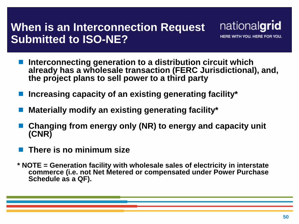
When is an Interconnection Request Submitted to ISO-NE?
Interconnecting generation to a distribution circuit which already has a wholesale transaction (FERC Jurisdictional), and, the project plans to sell power to a third party
Increasing capacity of an existing generating facility* Materially modify an existing generating facility* Changing from energy only (NR) to energy and capacity unit
(CNR) There is no minimum size
* NOTE = Generation facility with wholesale sales of electricity in interstate
commerce (i.e. not Net Metered or compensated under Power Purchase Schedule as a QF).

Break: 5 Minutes, then Follow up Questions
51

52
DG Engineering
Studies and Analysis
Distribution Planning & Asset Management
Jeff Cahill

Technical Discussion
Potential Impacts of DG on Distribution EPS
System Modeling Studies
Transformer Limits
Radial Systems versus Secondary Network Systems
Anti-Islanding
53

Interconnection Standards –
Industry Standards, Codes, Regulatory
Rules, Local Rules, Product Standards
What are industry standards and codes that apply to DG
interconnections to the EPS?
IEEE standards applicable to DG installations:
IEEE 1547 “Standard for Distributed Resources Interconnected with Electric Power Systems”
IEEE 1547 references several other standards, such as but not limited to the C37.90 series.
54

Interconnection Standards – Industry Standards, Codes,
Regulatory Rules, Local Rules, Product Standards
Federal Government
FERC SGIP “Small Generator Interconnection Procedure” http://www.ferc.gov/EventCalendar/Files/20050512110357-order2006.pdf
Regional
NERC Standard FAC-001-0 - Facility Connection Requirements
Standard PRC-002-NPCC-01 - Disturbance Monitoring
State Government
New York Department of Public Service (NY DPS)
PSC NY Standardized Interconnection Requirements for Distributed Generation Connected to the Distribution EPS (NY SIR)
Niagara Mohawk d/b/a National Grid tariff, P.S.C. 220
Massachusetts Department of Public Utilities (MA DPU)
Massachusetts Electric d/b/a National Grid tariff, M.D.P.U. 1320
Rhode Island Public Utilities Commission (RI PUC)
Narragansett Electric d/b/a National Grid tariff, R.I.P.U.C. 2078 https://www.nationalgridus.com/non_html/shared_interconnectStds_RI.pdf
55

Interconnection Standards – Industry Standards, Codes, Regulatory
Rules, Local Rules, Product Standards
ESB 750 Specifications for Electrical Installations
ESB 756 General Requirements for Parallel Generation Connected to a National Grid Owned EPS
- Appendix A Requirements for Parallel Generation Connected to National Grid Facilities in NY
- Appendix B Distributed Generation Connected To National Grid Distribution Facilities per the NYS SIR
- Appendix C Distributed Generation Connected To National Grid Distribution Facilities per the MA SIDG (September 2015, Version 3.0)
- Appendix D Distributed Generation Connected To National Grid Distribution Facilities per the RI SCDG (R.I.P.U.C. 2078, November 2011 tariff.)
- Appendix E Requirements for Parallel Generation Connected to National Grid Facilities in New Hampshire
The Appendices to ESB 756 are intended for jurisdictional-specific requirements.
http://www.nationalgridus.com/non_html/shared_constr_esb756.pdf
Each utility has their requirements pursuant to the regulations that govern
them as varying from state-to-state based on the NESC.
56

57
Key Points for Electric
Service Requirements:
Require some means of
disconnect and main
overcurrent protection,
i.e., service equipment.
Billing meters secure.
Interface points clear to
avoid potential
operating and safety
problems.
Key Points for Parallel Generation Requirements: Company determines the
interconnect voltage and method of interconnection.
Prior notification to and approval by the Company is required for any generation to be installed or operated in parallel with the Company
EPS.
Interconnection Standards – Industry Standards, Codes, Regulatory
Rules, Local Rules, Product Standards
www.nationalgridus.com/electricalspecifications
57

ESB 756 references all requirements for parallel generation connected to National Grid facilities located in Upstate New York, Massachusetts, and Rhode Island.
The purpose of this National Grid Electric System Bulletin (ESB) is to:
1. Provide general requirements and recommendations for all generators connected in parallel with the electric power system (EPS) operated by National Grid (Company). Stand alone generators serving isolated load, which can never be connected in parallel with the Company EPS, are not subject to these requirements.
2. Ensure compliance with NERC Standard FAC-001-0 – Facility Connection Requirements, effective April 1, 2005. Along with all of the Company’s Electric System Bulletins, the most current version of ESB 756 is available electronically on its National Grid USA web page at: www.nationalgridus.com/electricalspecifications.
3. Ensure that the electrical reliability and security of the Company EPS and the larger power system grid is maintained following connection of the parallel generator to the utility supply.
4. Refer Generator-owners to the applicable FERC or state-specific tariff regulations pertaining to parallel generators.
Interconnection Standards – Industry Standards, Codes, Regulatory
Rules, Local Rules, Product Standards
58

Potential Impacts of DG on Distribution EPS
Customer generation connected to the distribution system can cause a
variety of system impacts including steady state and transient voltage
changes, harmonic distortion, and increased fault current levels.
Technical Issues Integrating Distributed Generation
with the Utility Distribution EPS
59

System Modeling Studies
The purpose of impact studies is to identify the severity of system
impacts of the Customer’s generators and the upgrades needed to
avoid problems on the Company’s distribution electric power system
(EPS).
Careful engineering can effectively eliminate the potentially
adverse impacts that DG or distributed resource (DR)
penetration could impress on the electric delivery system, such
as exposing system and customer equipment to potential
damage, decrease in power quality, decrease in reliability,
extended time to restoration after outage, and potential risks
to public and worker safety.
Technical Issues Integrating Distributed Generation
with the Utility Distribution EPS
60

61
The IEEE supports the following system issues that the utility industry faces with DG penetration on the local EPS, but not limited to:
voltage
capacitor operations
flicker and voltage regulator and LTC operations
protection coordination
feeding faults after utility protection opens
interrupting rating of devices
faults on adjacent feeders
fault detection
ground source impacts and ground fault overvoltages
single phase interruption on three phase line
recloser coordination
Technical Issues: System Modeling Studies
thermal overload and conductor burndown
risk-of-islanding:
loss of power grid and sensitivity under light load
vulnerability and overvoltages
system restoration and network issues
harmonic distortion contributions
power system stability and impact to bulk power network
system reinforcement
metering
telemetering

Transformer Limits- DG Installations less than 600V
The utility distribution transformers continuous duty
nameplate rating is applied to sizing for DG Customer
installations to ensure reliability of the supply.
Exceeding transformer nameplate rating from DG sources
affects the transformer normal loading capability and
transformer life cycle becomes shortened.
Replacement later due to overload by DG causes burden
on other customers on same feed!
Technical Issues Integrating Distributed Generation
with the Utility Distribution EPS
62

63
Radial Systems versus Secondary Network Systems
Technical Issues Integrating Distributed Generation
with the Utility Distribution EPS
Area Networks consist of one or more primary circuits from one or more substations or
transmission supply points arranged such that they collectively feed secondary circuits
serving one (a spot network) or more (an area network) Interconnecting Customers.

Technical Issues: Limits on Distribution EPS - Radial
DG saturation refers to the point at which large amounts of parallel generation
are installed, whether by a single large facility or multiple facilities in
aggregate, such that it becomes technically infeasible to operate on a single
distribution feeder.
A resulting example is excessive voltage regulation issues associated with
intermittent resources like solar and wind. IEEE 1547 is recognized by the
applicable Company tariff, P.S.C. 220 Rule 53 providing technical guidance
whereby voltage regulation impacted by DG is a limiting factor.
It is expected due to the DG market that distribution feeders in many areas
will reach the saturation point based on the application growth rate in those
areas.
Stability issues due to generation exceeding the feeder load causing back
feed to the transmission system will need to be addressed where DG saturation
occurs.
64
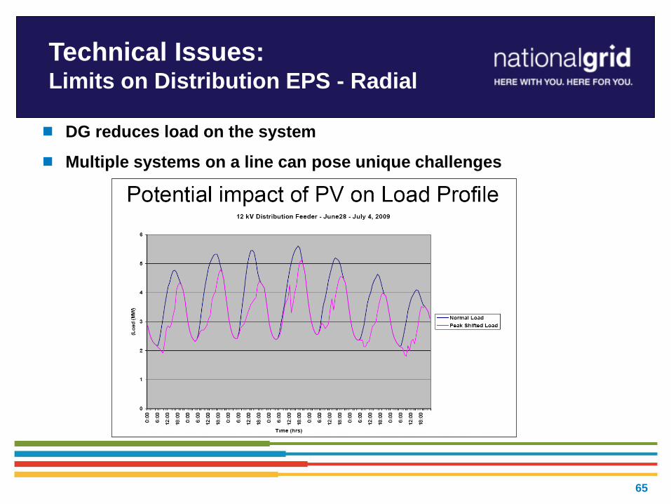
DG reduces load on the system
Multiple systems on a line can pose unique challenges
Technical Issues: Limits on Distribution EPS - Radial
65

Technical Issues: Limits on Distribution EPS - Radial
First check – “How is
EPS affected and how
much is acceptable on it
(other customers on the
feeder)?”
Example: Intermittent Resources - Large PV Inverter-based DG:
Ramp rates of large PV inverter-based generators can affect EPS operations and power quality.
Geographic diversity effects not yet fully understood.
66

67
Electric Service Bulletin (ESB) requirements have changed as of Nov.
15, 2016.
In most cases, certified inverter projects would no longer require direct
transfer trip (DTT).
For generation projects without customer load, a utility owned point of
common coupling (PCC) recloser may be required. This may allow the
customer to provide simpler service installations.
Where PCC reclosers are required, in most cases, a remote terminal unit
(RTU) would not be required.
This policy will be included in the next revision of ESB 756C, which will
be published later this year
November 2016 Islanding Policy
Summary

68
Zero Sequence Overvoltage
(3V0)
For single-line-to-ground faults on the delta side of substation delta-
wye-ground transformers, over-voltages may occur where significant
amounts of DG are connected on the wye side of the transformer
Impact studies evaluate total DG on the substation versus total
minimum load
If risk of overvoltage condition is present, additional substation
protection required:
CCVT’s
59N relaying
Control wiring to trip all wye-ground (low) side breakers
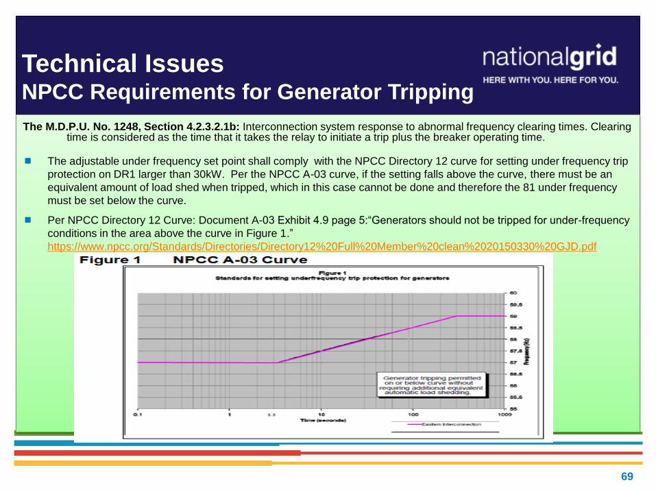
The M.D.P.U. No. 1248, Section 4.2.3.2.1b: Interconnection system response to abnormal frequency clearing times. Clearing time is considered as the time that it takes the relay to initiate a trip plus the breaker operating time.
The adjustable under frequency set point shall comply with the NPCC Directory 12 curve for setting under frequency trip
protection on DR1 larger than 30kW. Per the NPCC A-03 curve, if the setting falls above the curve, there must be an
equivalent amount of load shed when tripped, which in this case cannot be done and therefore the 81 under frequency
must be set below the curve.
Per NPCC Directory 12 Curve: Document A-03 Exhibit 4.9 page 5:“Generators should not be tripped for under-frequency
conditions in the area above the curve in Figure 1.”
https://www.npcc.org/Standards/Directories/Directory12%20Full%20Member%20clean%2020150330%20GJD.pdf
Technical Issues NPCC Requirements for Generator Tripping
69

The M.D.P.U. No. 1320, Section 4.2.3.2.1b: Interconnection system response to abnormal frequency clearing times. Clearing time is considered as the time that it takes the relay to initiate a trip plus the breaker operating time.
Clarifying points to avoid potential Issues causing non-compliance to the NPCC and IEEE 1547 standard
Aggregate generation under 30kW is acceptable if documentation is provided showing UL1741 “listed” inverters
Aggregate generation greater than 30kW: UL1741 “listed” inverters are required to provide confirmation of settings from
above table. This means if multiple string inverters less than 30kW are used for a site that aggregates greater than 30
kW, the appropriate settings from the table should be loaded in the inverters for UL 1741 testing.
Technical Issues NPCC Requirements for Generator Tripping
Continued…
70

Technical Issues NPCC Requirements for Generator Tripping
Examples:
71
Example 1:
81U UNDER-FREQUENCY
RELAY
STEP 1: PICKUP 57 HERTZ, TIME
DELAY 10 CYCLES
STEP 2: PICKUP 58.5 HERTZ, TIME
DELAY 6,000 CYCLES
81O OVER-FREQUENCY
RELAY
PICKUP 60.5 HERTZ, TIME
DELAY 10 CYCLES
Example 2:
81U
57.0 Hz 0.16 SEC (10
CYCLE) DELAY
59.0 Hz 300 SEC (18,000
CYCLE) DELAY
81O 60.5 Hz
0.16 SEC (10 CYCLE) DELAY
*Times listed are total clear (should include breaker/interrupter time, detection time, etc.)
11
ERV Basics
Post ISA Coordination
Customer Energy Integration Hakob Mkrtchyan

Post ISA Coordination Engineering, Procurement & Construction Process (Overview)
ISA Execution
• Payment Plan
• Kick-off Meeting
• Preliminary Engineering
• Milestone Plan
Design
• Field Investigation
• Detailed Design Sketches and Specifications
• Construction grade estimates
Procurement/ Permits
• Procuring Long Lead items
• Securing Easements, Right of Way access and/or Environmental permits/ licenses
Engineering
• Recloser and Primary Meter
• Company System Updates
• Compliance Verification
Construction
• Advanced notice for scheduling
• Field Check
• Outage coordination
• Construction
Energization, Testing & Commissioning
• Field Commissioning and Energization
• Relay Test
• RTU Test
• Customer Commissioning
Customer Interface: TSES, Customer Service, and Customer Solutions
Po
st
ISA
Co
ord
inati
on
- E
ng
inee
rin
g,
Pro
cu
rem
en
t &
Co
nstr
ucti
on
Pro
ce
ss
Overv
iew
73

Post ISA Coordination (cont’d) Witness Testing Process Overview
74
Witness Test Documents
• IC submits WT Documents
•Company reviews & approves WT documents
• IC Submits Pre-testing results
•Call to discuss test results and sequence of events
Scheduling Witness Test
• IC requests WT date
•Company confirms WT date & sequence of events
•Company coordinates WT with internal groups
Day of Witness Test
•Relay test
•Functional Trip test
• In-service checks
•Generator/Inverter relay test
Authority To Interconnect
•Company reviews & approves test results
•Company confirms receipts of all compliance documentation
•Company to issue AI letter
• In case of IPP, the site will ONLY be energized first time on the day of the witness test after
successful completion of relay test and functional trip test.
• Customer shall perform pre-testing using their own generator source.
• The Company needs at least 10 day advance notice to schedule a witness test.
• It is recommended to submit witness test documents at least 30 days prior to the witness test.

Post ISA Coordination Key Items
• Developing Project Schedule including Interconnection Tasks
• Procuring communication lines for Interconnection – MPLS circuit and Telephone line
• Verizon High Voltage Protection Requirements
• Other Utility Costs
• Design/ Equipment Changes
• Municipal Inspection
• Verizon Pole Installation and Payment
• Testing and Commissioning Plan
• Test Procedure
• Energization Plan
• Long term O&M Arrangement
Note: Please plan ahead for all close-out activities, like witness testing, as they can be time
consuming to coordinate and complete. Please keep all critical milestone date or deadline
of commercial operation of the system in mind while planning for witness test.
75
Plan
Ahead!

76
First Bill Walkthrough
Customer Energy Integration
Colin Walker

77
Basics of Net Metering
When you are using more power than you are generating, your
meter registers positive. You are importing power from your electric
company.
When you are generating more power than you are using, your
meter registers negative. You are exporting power to your electric
company.
In any billing period where exported energy exceeds imported, your
electric bill will show negative use. You are a net exporter for the
billing period, and are entitled to a Net Metering Credit.
Important: Standard utility meters cannot differentiate between import and export. A
bi-directional meter is needed to properly record directional flow.

78
Net Metering – Simple
Example

79
Net Metering Credit Amount

80
Bill Display
What will this look like on my bill?
Net Export is the basis for Net Metering Credit, and appears in
“Metered Usage” section
Net Metering Credits appear in “Delivery Services” section
Net Metering Credits are calculated using the retail rate, which may
include several types of charges (block rates, time-of-use, demand
charges, etc.)
Calculation depends on rate, class, and load zone
With different rate structures and use patterns, credit may not appear
the same on every net metered account.
81
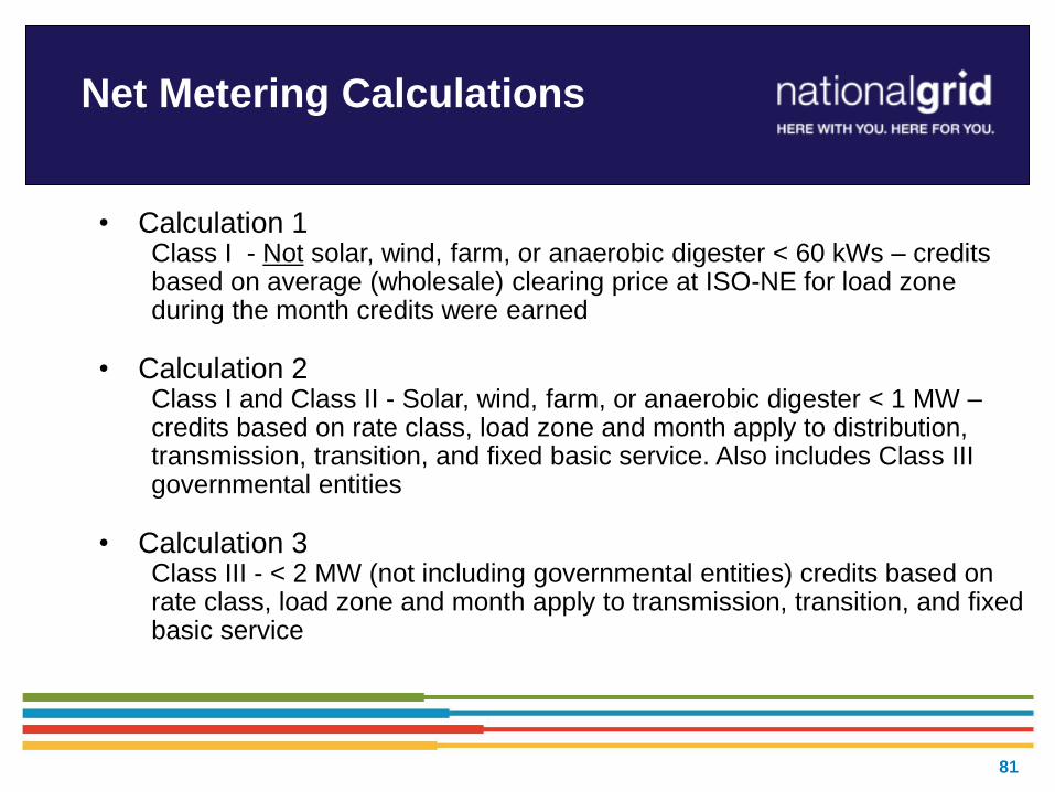
Net Metering Calculations
• Calculation 1 Class I - Not solar, wind, farm, or anaerobic digester < 60 kWs – credits based on average (wholesale) clearing price at ISO-NE for load zone during the month credits were earned
• Calculation 2 Class I and Class II - Solar, wind, farm, or anaerobic digester < 1 MW – credits based on rate class, load zone and month apply to distribution, transmission, transition, and fixed basic service. Also includes Class III governmental entities
• Calculation 3 Class III - < 2 MW (not including governmental entities) credits based on rate class, load zone and month apply to transmission, transition, and fixed basic service

82
Bill Display - Calculation 1 (QF
under 60 kW)
Qualifying Facilities under 60 kW are reimbursed based on ISO-NE monthly
average clearing price X net exported kWh

83
Bill Display - Calculation 2
(G2)
Some rate structures do not contain blocked or time of use rates, which
allows us to display the Net Metering Credit on one line on the bill.
Net Metering Credit includes: transmission, transition, distribution, and basic
service credits

84
Bill Display - Calculation 2
with a block rate (G1, R1, R2)
Block rate formats require Distribution Charges be displayed in the manner below
Net Met Cr Other is a combination of transmission, transition, and basic service credits
Net Met Cr First is the distribution credit for the first 600 kWh
Net Met Cr Next is the distribution credit for usage beyond first 600 kWh

85
Rate G-3 (Time-of-Use)
Example
Net Met Credit Other is a combination of transmission, transition, and basic
service credits
Net Metering Credits are calculated on both the Peak and Off Peak schedule
Net Metering Credit is the sum of Peak, Off Peak and basic service credits.

86
Bill Display - Calculation 3 (class III)
This calculation does not include Distribution Charges, so there are no issues
related to blocked or TOU rates; therefore, we can display the Net Metering
Credit on one line on the bill.

87
Schedule Z
Schedule Z is used to allocate Net Metering Credits from a Host
Account to “target” account(s)
Net Metering Credits are calculated using certain components of
the retail rate of the Host Account
The value of the Net Metering Credit depends on the rate of the
Host and the class of the Net Metering Facility
National Grid transfers credits, on a percentage basis, to accounts
listed on your Schedule Z
Important: There is no mechanism for transferring specific dollar amounts, only
percentages of Net Metering Credits

88
Transfer of Credits
When can I expect to see the first transfer of credits?
The first Net Metering Credit may not appear until the month following the first bill after you received formal Authorization to Interconnect
Each month the Host Account meter is read and net export is used to calculate Net Metering Credits for that month.
Our Accounts Processing group transfers credits, as directed on Schedule Z.
Typically, Net Metering Credits are transferred to “target” accounts about 1-2 weeks after Host Account has billed.
Net Metering Credits will be displayed on both the Host Account and “target” accounts on the next month’s bill
As Host Customers and “target” customers may not be in the same billing cycle, transfers from one month may not show up until the following month, and may not always occur on the same date.

89
FAQ’s
How often can I change my Schedule Z allocation(s)?
Customers are allowed to change Schedule Z twice a year.
When will my new Schedule Z allocation(s) take effect?
When we receive a revised Schedule Z, the account(s) are updated.
Changes should take effect the following billing cycle.
Will the bill show credits transferred from Host Account to “target”
accounts?
Host Account will show “Transfer Credit”, and $ amount
“Target” account will show “Transfer Credit” and $ amount
Host Account will not show “target” account numbers
“Target” account will not show Host Account number.

90
Host to Target Customer Credit
Transfer

91 91
92 92

93
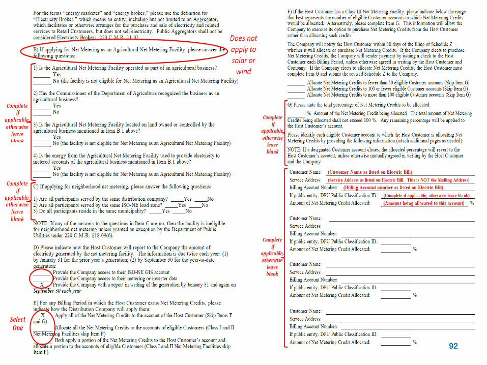
Net Metering – filling out
Schedule Z, last page

94
2017 DG Seminars – MA
• Today (National Grid – Waltham)
• August 23, 2017 (Eversource -- formerly WMECo) -- Hadley
• September 13, 2017 (Eversource East – formerly NSTAR)
• October 19, 2017 (National Grid -- North Andover/Brockton)
• November 2, 2017 (Eversource -- formerly WMECo) -- Hadley
• December 13, 2017 (Eversource East – formerly NSTAR)

Question and Answer
Contact for Follow-Up Questions:
Email: [email protected]
95
Thank you for Participating!