
DISTRIBUTED BY: National Technical Information Service ...1 ABSTRACT Using th, foil bearing...
95
I AD-768 454 DYNAMIC AND ENVIRONMENTAL EVALUATION OF COMPLAINT FOIL GAS LUBRICATED BEARING D. E. Heuer, et al Airesearch Manufacturing Company of Arizona Prepared for: Air Force Aero Propulsion Labora-tory June 1973 DISTRIBUTED BY: National Technical Information Service U. S. DEPARTMENT OF COMMERCE 5285 Port Royal Road, Springfield Va. 22151
Transcript of DISTRIBUTED BY: National Technical Information Service ...1 ABSTRACT Using th, foil bearing...

I
AD-768 454
DYNAMIC AND ENVIRONMENTAL EVALUATION OFCOMPLAINT FOIL GAS LUBRICATED BEARING
D. E. Heuer, et al
Airesearch Manufacturing Company of Arizona
Prepared for:
Air Force Aero Propulsion Labora-tory
June 1973
DISTRIBUTED BY:
National Technical Information ServiceU. S. DEPARTMENT OF COMMERCE5285 Port Royal Road, Springfield Va. 22151

UNCLASSIFID
DOCUMENT CONTROL DATA - R & D-Ser's'ly my.,"Z eP. t Wye P,'fr 1 9 s4u. .a-, -On I e'trf wl'.n F" oeall ter.-,f a -. etna 38tid,
I OPWNA Ic Ac T - Wy .Cnor t su'ho?) 12 . .COORT SCC ,R ',r Ct.1SS.aFICA Z-0
AiResearch Manufacturing Company of Arizona UNCLASSIFIEDA Division of The Garrett Corporation |b. GueoP402 So. 36th Street, Phoenix, Arizona 85034
R EPORT -,DYNA IC AND ELVIRONMENTAL E1YALUATION OF COMPLAINT FOIL GAS LUBRICATEDBEARINGS
a =CS-' zP- vC ,.TES 7"¢pe of-repoer ard Inclusive dates)
Final
D.E. HeuerR.A. Collins
93EPORT GATE 7. TOYAL PO OF PAGES 'b. No OF REPS
June 1973 iq0fs4 CZ%TRAC- OR G"N~' Pao go. ORIGINAT01*W SPOgt- NWJMLCRMS
F33615-72-C-1802 73-310169b. PRO eCT nO
2. OT64E REPORT NOS3 (Any othernumberS thata my be assignedthis report)
AFAPL-TR-73-5650 ZISTRIOUTION STA-EMEN-
Approved for public release; distribution unlimited
S,,PLEMENTARY NOTES (2. SPO-JSORiNG MP4LITARY ACTIVITY
Air Force Aero Propulsion Laborator__3 ____________ Wright-Patterson AFB, Ohio 45433
"3 ASSTRA¢C
This report summarizes the work accomplished under USAF ContractF33615-72-C-1802 by the AiResearch Manufacturing Company of Arizona, during the period from April 1972 to Nay 1973. A series of demonstrationtests, similar to those required for engine qualification, were conduc-ted on a gas turbine engine utilizing gas lubricated compliant foilbearings.
The engine operated successfully throughout the water ingestion and dustingestion tests. When subjected to high-yaw maneuver rates, which sub-jected the bearings to high gyroscopic moment loads, the ultimate loadcapacity of the bearings was reached. When subjected to high vibration,structural resonance was incurred which amplified the input vibration atthe bearing carrier. The forward journal bearing did not sur~rive thetest but its vibrational loading waq 5 times what was originally intendeeResults of the overtefperature test indicated that the present bearingcoating is acceptable up to approximately 550 0F, but higher temperaturecoatings would be required if the bearings should be installed in new,advanced-design engines.
D D byo 7 C, o,,1 4, NATIONAL TECHNICAL UNCLASSIFIED
INFORMATION SERVICE Security ClassificationU S Deparlniet of Commerce
Sp,;-gf1'|J VA 22151

Unclassified
14 L.Pdp AI| ----ii--I1i I-i....I
Foil Bearings IGas Lubrication fCompliant Bearings
Gas Lubricated Compliant Bearings
Gas Lubricated Foil Bearings
Hydrodynamic Gas Lubrication
Turbine Engine Lubrication
I IJ
UnclassifiedSecurity Classification
UNCLASSIFIED
AFAPL-TR-73-56 I't
DYNAMIC AND ENVIRONMENTAL IEVALUATION OF COMPLIANT FOIL
GAS LUBRICATED BEARINGS
D.F. HEUERR.A. COLLINS
AIRESEARCH MANUFACTURING COMPANYOF ARIZONA
Approved for public release;
distribution unlimited
UNCLASSIFIED

MR7.10RD
This report was prepared by The AiResearch 1V.anufacturing Company ofArizona, A Division of The Garrett Corporation, Phoenix, Arizona. TheacL-ivities discussed in this report were Liitiated under United StatesAir Force Contract F336!5-72-C-1802. The contract was administered bythe Aero Propulsion laboratory, Aeronautical Systems Division, Air ForceSystems Cozrnnd, right-Patterson Air Force Base, Ohio with Mr. E.A. Le-eact.Lng as Project Engineer.
A series of demonstration tests, similar to those required for militaryengine aualification, were conducted on a gas turbine engine utilizinggas ubricated compliant foil bearings. The tests were conducted duringtrje time period from April 1972 to May 1973.
This report is assigned a supplementary report number, 73-310169, byAiResearch Manufacturing Company.
The authors wish to ackiowledge contributions made by other individualswithin The Garrett Corporation, especially P. Gerba, B.B. Heath, N.M.Hi:ghes, J.T. Irwin, J.M. McVaugh, A. Silver, and J. Wenban.
This report was submitted by the authors on May 16, 1973.
ruLoll-ation of this report does not constitut Air Force approval of the -1report's findings or conclusions. It is published only for the exchangeand stimulation of ideas.
CHARMES R. HUDSONChief, Fuels and Lubrication DivisionAir Force Aero Propulsion Laboratory
IIF

1ABSTRACT
Using th, foil bearing demonstrator, which is a small, 95-poundthrust turbojet engine developed from an existing jet fuel starterunder U.S. Air Force Contract F33615-71-C-1376 and described inTechnical Report AFAPL-TR-72-41, a series of evaluation testswas conducted to demonstrate that a gas turbine engine, mountedon gas-lubricated, compliant foil bearings, has the potentialfor qualification in a military application.
The engine operated successfully throughout the water ingestionand dust ingestion tests.
When the engine was subjected to high-yaw maneuver rates, whichsubject the bearings to high gyroscopic moment loads, the ulti-mate load capacity of the bearings was reached, indicating addi-tional development to increase the load-carrying capability ofthe bearings may be desirable.
When the engine was subjected to high vibrational loading, astructural resonance was incurred which amplified the inputvibration at the bearing carrier. The forward journal bearingdid not survive the test but its vibrational loading was 5 timeswhat was originally intended. The ability of the foil bearingsto withstand vibrational loading is dependent upon the enginestructural hardware, which must isolate the external vibrationfrom the bearing carriers. This phenomena becomes peculiar tothe individual engine design.
Results of the overtemperature test indicate that the presentbearing coating is acceptable up to approximately 5500 F, buthigher temperature coatings would be required if the bearingsshould be installed in new, advanced-design egctines, which wouldhave such high pressure ratios that the compressor discharqetemperature would be hotter thai the coating tamperature limitation.
iii

TABLE OF CONTENTS
Page
I. INTRODUCTION .... .. ................ .................... ... .. ... !
lo ADVANTAGES !
a. Simplicityb. Reduced 11aintenance and Added Reliability ......... 1c. Reduced Vulnerability ............... o.. .. ...... od. High-temperature Operation ...... 1 o.. ..........e. Reduced Weight ......................... . .. ..... 2f. Cost Sa-:ing . . . . . . . . . . . . . . . . . . .. 2
2. BACKGROUND ... . . . .. . . ................ ......... 2
a. Development Program ........................... 2b. Evaluation Program ... .......... *......... 3
II. PROGRIM DESCRIPTION .......... . ............. . ............ 4
1. ENGINE DEVELOPMENT ............ ....... 4
2. TEST PROGRAM DEVELOPMENT ............................... 4
3. DESCRIPTION OF EQUIPMENT ........... o.................. 5
a. Engine .. ...... ..... ... ..... oo... -...... .. . .. . ... 5b. Bearings .. ....... ... o...... o........ -..... .. .. . .. 14
c. Instrumentation ............. o.. ............ 19
4. TEST PROGRA1M ........ . ................................ 24
a. Water Ingestion Test ...... .... ... .............. 24b. Dust Ingestion Test ............*........ .... 26c. Maneuver Loading Test ............................ 34d. Vibration Test ... . .... ......... . ........... o ... o. 62e. Foil Bearing Overtemperature Test ........ o....... 72
III. CONCLUSIONS AND RECOMIENDATIONS ............................ 82
Preceding page blank v
LIST OF ILLUSTRATIONS
Figure Paqe
1 Modifications to jet fuel starter for foil bearing demonstrator .. ..... 6
2 Three-fourths front view of foil bearing demonstrator in testconfiguration ......... ..... .............................. 7
3 Engine layout ......... ..... .............................. 8
4 Sea-level standard-day performance characteristics, foil bearingdemonstrator ......... ...... .............................. 9
S Cooling air flcw paths and orifice sizes in foil bearingdemonstrator ......... ... .............................. .. 11
6 Bearing load versus shaft speed, foil bearing demonstrator . ....... ... 12
7 Foil bearing demonstrator control panel and electroniccontrol assembly ......... .. ............................ ... 13
8 Changes to original foil bearing demonstrator for conversion toair motoring mode ......... .... ........................... 15
9 Plenum air pressure versus speed in the air motoring mode .......... . 16
10 Journal bearing selected for foil bearing demonstration .. ......... ... 17
11 Thrust bearing set selected for foil bearing demonstrator .......... . 18
12 Performance map for journal bearings ........ .................. 20
13 Load capacity of thrust bearing ........ ..................... ... 21
14 Aerodynamic thrust as a function of speed ...... ................ ... 22
15 Engine instrumentation .......... ......................... ... 23
16 View of water nozzle directed toward inlet of engine prior to startof water ingestion test .......... .......................... 25
17 Ten-power magnification of journal bearing foil segments afterwater ingestion test .......... .......................... ... 27
18 Ten-power magnification of forward thrust bearing foil segmentsafter water ingestion test ......... ....................... ... 28
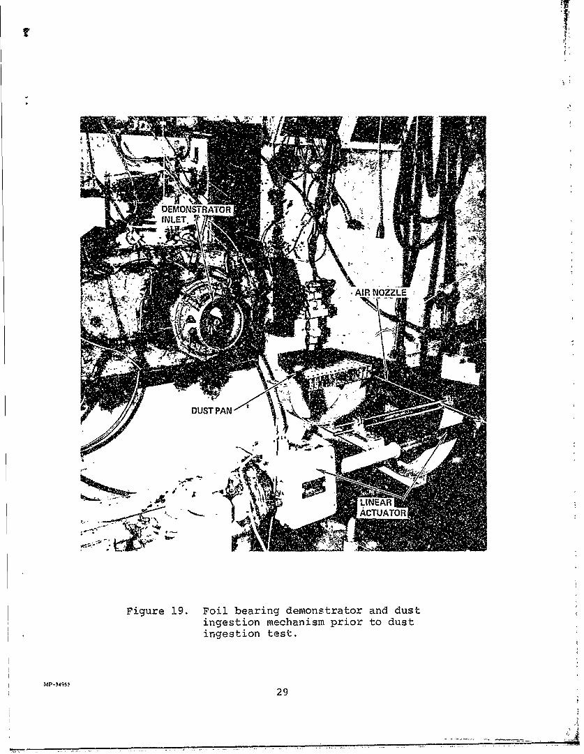
19 Foil bearing demonstrator and dust ingestion mechanism prior todust ingestion test .......................... 29
20 Journal bearing foil segments after dust ingestion test .......... .. 31
21 Forward and aft thrust bearing assemblies after dust ingestion ..... ... 32
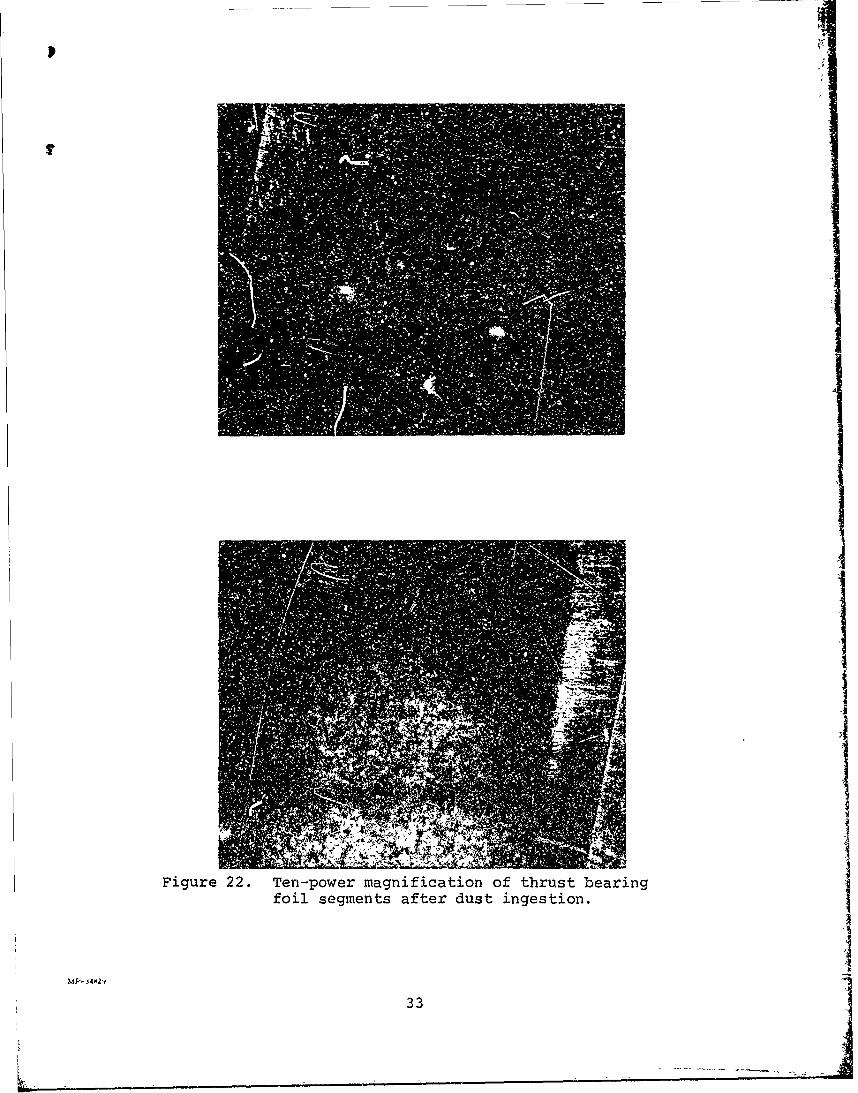
72 Ten-power magnification of thrust bearing foil segments afterdust ingestio ........ ....... ............................. 33
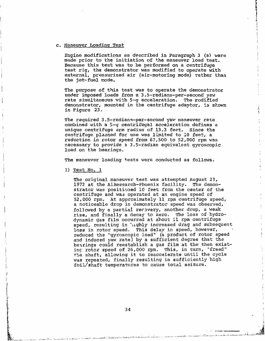
23 Front view of modified foil bearing demonstrator mounted oncentrifuge adapter prior to maneuver load test .... ............. ... 35
24 Compressor-end journal bearing foil segments after maneuver loadtest (top of photograph oriented toward front of engine, as installed). 37
vi

LIST OF ILLUSTRATIONS (Contd)
Figu1re Page
25 Turbine-end journal bearing foil segments after maneuver load test(bottom of photograph oriented toward rear of engine, as installed) . . . 38
26 Journal shaft/thrust runner after maneuver load test ..... ........ .39
27 Instrumentation locations in foil bearing demonstrator .... ......... 40
28 Cooling airflow pressure distribution in foil bearing demonstrator .. . 41
29 Schematic diagram of foil bearing demonstrator mounted in Mint Canyon
centrifuge test facility ....... .... ........................ 44
30 Overall view of centrifuge test facility ............. ................ 45
31 Close-up view of foil bearing demonstrator mounted near end ofcentrifuge arm (note insulated air supply duct) ...... ............. 46
32 View of centrifuge test instrumentation showing centrifuge drivecontrol, Offner 8-channel recorder, signal conditioner, andTVmonitor ....... ...... ............................... .47
33 Foil bearing demonstrator maneuver load test, January 4, 1973,Mint Canyon Test Facility ......... ........................ ... 50
34(a) Forward thrust bearing surface ....... ..................... . ...
34(b) Aft thrust bearing surface ....... .. ....................... .. 51
35 Forward thrust runner face ....... .. ....................... .. 52
36 Aft thrust runner face and journal shaft ................ 53
37 Analytic free-body of foil bearing demonstrator rotating group ...... .55
38 Axial thrust foil bearing load-deflection characteristics .......... .. 57
39 Radial thrust foil bearing load-deflectioa characteristics ......... .58
40 Isometric diagram of impostd loads upon compressor journal bearingseizure . . . . . . . . . . . . . . . . . . . . . . . . . . . . . . . . . 59
41 Coaxial and skewed shaft journial bearing load profile comparison . . . . 61
42 Side view of foil bearing demonstrator mounted on vibration table . . . . 63
43 Vibration Curve "C" Figure 514.1 in MIL-STD-810B .... ............ .64
44 Oscillograph recording of vibration test ........ ................ 65
45 View of shaft and two thrust bearings after disassembly uponcompletion of vibration test ....... .. ...................... .67
46 Close-up view of back (turbine) journal bearing ...... ............. 68
47 Single degree of freedom amplification factors .... ............. .. 69
48 Estimated system amplification factors ........ ................. 70
49 Thrust bearing thermocouple location ...... .................. ... 75
50 Front view of foil bearing demonstratcr installed in overtemperaturetest facility ........ .... ............................ ... 76
51 Sandborn trace showing final sec;onds of overtemperature test.. . . . . . 79
52 View of forward thrust foil bearing after disassembly .... ......... 80
vii

ii
LIST OF TABLES
Table Page
I Summary of Recorded Parameters During ManeuverLQad Test at Mint Canyon ........ .... 49
II Pertinent Test Information from Phoenix and MintCanyon Maneuver Load Tests...... . . . . . . . . 54
III Results of Bearing Forces and Average Loads Carriedby Each Bearing During Mint Canyon Maneuver Test . . . 60
IV Data Obtained from Sandborn Recording of Foil BearingOvertemperature Test. . . . . . . . . . . . . . .. . 77
viii
A
SECTION I
INTRODUCTION
Gas-lubricated foil bearings show the potential for providing theadvantages of simplicity, reduced maintenance, added reliabil-ity, reduced vulnerability, high-temperature operation, reducedweight, and cost savings to an advanced engine system.
1. ADVANTAGES
a. Simplicity
Simplicity of gas-lubricated bearings is effected by theabsence of a complicated delivery and scavenge oil network,especially critical at the hot end journal bearing whereoil crosses the engine exhaust path upon entering andleaving the bearing cnvity. In this area, extensivedevelopment is sometimes necessary to prevent high oiltemperature during soakback, which often reduces enginereliability and time-between-overhaul.
b. Reduced Maintenance and Added Reliability
The use of gas bearings will eliminate the possibility ofoil contaminating the bleed-air supply (environmentalcontrol system) or the engine exhaust, as a result ofoil seal leakage.
The endurance capability of the foil bearings has beenproven by foil bearing-equipped production DC-10 coolingturbines which have accu'mulated mrore than 650,000 hoursin scheduled airline service in more than 50 aircraftwith a mean-time-between-unscheduled-removal (MTRUR) of90,000 operating hours. The longest-mean-time unit hascompleted more than 8000 hours, with the number ofstarts estimated to be over 2000, conducted over a widerange of ambient temperature conditions.
7c. Reduced Vulnerability
Since the foil bearings do not require external enginehardware, such as oil lines and an oil heat exchanger, thevulnerability of the engine is reduced.
d. High-Temperature Operation
At present, limitations on foil bearing temperature havebeen due to foil coating. Advancements in foil coatingtemperature tolerance will be achieved in time, asresearch on the problem continues. Because the airviscosity increases with temperature, a hotter-runningbearing will provide higher load capacity, thus makinghigh temperature operation desirable.
1
,A

e. Reduced Weight
A weight saving can be effected by the reQtion inoil capacity required by a system incorporati.cr foilbearings, assuming that an engine gearbox is sllrequired. The reduced oil capacity, in turn, woildreduce capacity requirements for the oil heat exchamgerand the oil pump. Elimination of oil delivery andscavenge networks results in a less complex, more uniform,and a lighter weight assembly. The weight saving,however, is compromised by the requirement for largerjournal bearings and "he addition of a thrust runner onthe rotor for the thru-_" bearing.
f. Cost Savinq
The inherent simplicity of t:he foil bearing lends itselfto rapid and easy fabrication. After an initial invest-ment in tooling, foils can be stamped or rolled out atlow cost. The greatest cost saving is realized byelimination of the oil network.
2. BACKGROUND
a. Development Program
The gas-lubricated foil bearings utilized for thisprogram are of a design patented by The GarrettCorporation. The bearings were initially developed forexperimental use in cooling turbines of the airconditioning system onboard the Boeing 727 airliner.
Observing this successful application to the coolingturbines and recognizing the advantages foil bearingsoffer to advanced military engioies, the U.S. Militarysponsored a feasibility study of the application ofgas-lubricated, compliant foil bearings to gasturbine engines. This initial program has been com-pleted and is described in Technical Report AFAPL-TR-72-41, dated June 1.972.
During this program, the foil bearing demonstrator wasdesigned and fabricated from the gas generator of anAiResearch Model JFSI00.-13A Jet Fuel Starter, which isused on the Air Force A7D light-attack aircraft. Mod-ifications to the original production equipment includedreplacing the rolling element bearings with compliantfoil gas bearings and replacing the power turbine modulewith an exhaust thrust nozzle. The resultant engine is
2

a ;5-pcund-static-thrust turbojet, mounted on compliantfoil gas bearings, totally free of oil and external air*supply, and operating at a design speed of 72,000 rpm.
The demonstrator was operated continuously for five hoursand underwent 135 start/stop cycles to full speed, asrequired by the demonstration contract.
b. Evaluation Program
This program was an extension to the development program.The evaluation program consisted of five test:, four ofwhich are often required for engine qualification. Thesetests, listed below, v:ere conducted to evaluate thepotential of utilizing foil gas bearings on engines thatmust undergo this type of qualification testing.
1) Engine water ingestion
2) Engine dust ingestion
3) Engine mane'ver (yaw and acceleration)
4) Engine vibration
5) Bearing overtemperature
This report provides a short description of the foil bearingdemonstrator and the several c(nfigurations used during the testsequence. A description of each test is provided, along with theconclusions drawn from the test data. Recommendations areincluded on those areas of the bearings that could benefit fromfurther development.
*An external impingement air supp.y is used to start the engine,but the bearings do not rely on this air for starting. Aiterlightoff occurs, this external air is shut down.
3

SECTION II
PROGRAM DESCRIPTION
The program objectave was to demonstrate the potential of a smallgas turbine engine equipped with compliant foil gas bearings foraealification in military installations.
1. ENGINE DEVELOPMENT
The engine, called the foil bearing demonstrator, was designedand fabricated from the gas generator of an AiResearch ModelJFSI00-13A Jet Fuel Starter, the rolling element bearings beingreplaced by compliant foil gas bearings. The development of theengine and gas bearings was accomplished in a previousprogram,under U.S. Air Force Contract F33615-71-C-137S, and is describedin Technical Report AFAPL-TR-72-41.
2. TEST PROGRAM DEVELOPMENT
A test program was established to determine the effect thatenvironmental and loaling conditions would have on the beaeingsduring engine qualification. The program consisted of thefollowing tests, each selected to evaluate potential areas ofbearing vulnerability.
Test Procedure
Water Ingestion Water sprayed into inlet withengine operating at governedspeed.
Dust Ingestion Dust sprayed into, inlet withengine operating at governedspeed.
Maneuver Load Engine operated on centriftge,subjected to 3.5 rad/sec yawrate simultaneous with 5--gacceleration.
Aibration Load Engine operated on vibrationtable, subjected to a vibrationalfrequency sweep from 14 to 500cps.
Bearing Overtempera- Cooling air introduced atture increasing temperature until
bearing operation was impaired.
A

3. DESCRIPTION OF EQUIPMNT
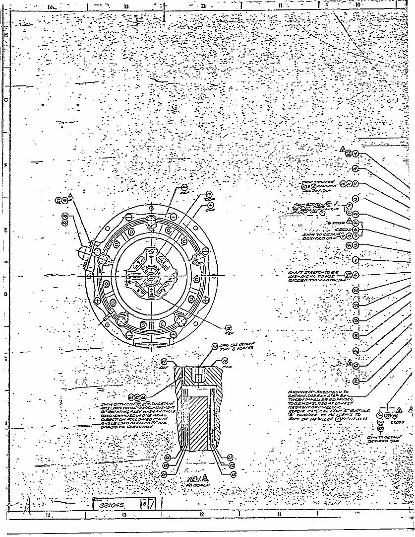
The foil bearing demonstrator was constructea by modifying thegas generator of an AiResearch Model JFSI00-!3A Jet Fuel Starter.The modifications, depictef in Figure 1, consist essentially ofreplacing the conventional rolling element bearings with compliantfoil gas bearings and replacing the original JFS power turbinemodule with a thrust nozzle.
The resultant "thrust" engine retains the aerodynaiic componentsof the original gas generator, requires no oil to operate, andcan generate up to 97 pounds of static thrust. A photograph ofthe engine is shown in Figure 2.
a. Engine
Th- engine layout is shown in Figure 3. The engineutiiizes a aingle-stage centrifugal compressor, whichgenerates a design pressure ratio of 3.2:1, and athrough-flow of 1.72 pounds per second at the full-ratedspeed of 72,000 rpm.
The annular combustor, equipped with five fuel nozzles,provides the turbine ilet temperature of 15800F. Theaxial turbine extracts a pressure ratio of 1.90 and theremaining pressure drop occurs through the exhaustnozzle (6.5-square-inch area) to provide the staticthrust. Figure 4 presents the engine performancecharacteristics as a function of the exhaust thrustnozzle discharge area.
The geometric and mass properties of the engine are asfollows.
Rotor Weight: 4.86 poundsPolar Moment of Inertia: 0.0138 in-lb-sec 2
Design Speed: 72,000 rpmJournal Bearing Diameter: 1.50 inchesThrust Bearing Diameter: 3.54 inchesEngine Length: 17 inchesEngine Width: 10 inchesEngine Height: 10 inches
The design of the rotor/bearing system was dictated, ir.part, by the adaptability of the foil bearing system 'coexisting parts of the jet fuel starter.
5
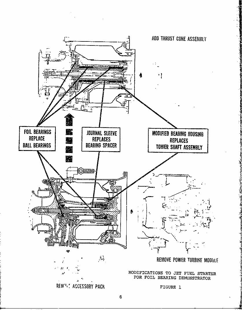
___________________ADD THRUST CONE ASSEMBLY
-_ __-__-----------_ _ _ _
FOIL BEARINGS JOURNAL SLEEVE MODIFIED BEARING HOUSINOREPLACE REPLACES IREPLACESBALL BEARINGS BEARING SPACER [TOWER SHAFT ASSEMBLY
A4REMOVE POWER TURBINE MODULE
MODIFICATIONS TO JET FUEL STARTERFOR FOIL BEARING DEMONSTRATOR
REM'v! ACCESSORY PACK FGR

44 -4
C
0 p
(D0
fits
41-
-3Z -
4: - J~. 3 - J. -z*-- Ti J~*~*1Icy-
P,.
co -. .. .. .. .. .- 7-. -- A.-a
-.- - - .-. 7 - -.. ..4.
Aeri
Are-- Av
-4-ZIC -. - A- ,
Gsozr --.v myy.
-13

4. .. -.....................
- S . . ~~~ .-- - - - . .-. , .... 5 . . . . . . .. ..................
97 'A w J799
at5~~5~ 70C- Y~ -- A1r--'-M
- --- . --
-
Al ;\1.!9.rjj'/

-4,,
AVO -V". 7. w ,
-~~~ I~. I.-- 1 A.
;i2g.- -
ENIN LAYOUT
Ore.""
c£FIGURE
........................-. - .-- A
B ~ ~ ~ ~ ~ y -.- -a-. - '
Pag 81045
M!2

!I
GAS GFNRATOR INLETSPEED = 72.'0130 RP 2M TMuPEU . 59 0Fz. -- 2000 - - -
T- I 1 100 EARO*T=R 29.92 IN. Fxg
1.7 1900 - - -9
1900 -- __90i800
1.65 80
1700 ?I4.C -_ 70Z6
1. 160 60
5 100 s
300 -- 40 4 o
2.-
1200 30
3 3 0 1_ _ _ L_-1_ '
30COMPRESSOR DISC1RGE 1002310 - TEMPERATURE, 0F300- 1 0 - T 10
320 , I I Io- -
2801 900 -0 -
6.0 6.25 6.5 6.75 7.0 6.0 6.25 6.5 6.75 7.0 6.0 6.25 6.5 6.75 7.0EFFECTIVE TMRUST NOZZLE AREA, IN. 2
Figure 4. Sea-level standard-day performancecharacteristics, foil bearing demonstrator.
9
,.

The bearing system is completely hydrodynamic and relieson compressor discharge air for pressurization andcooling. The cooling air flow path for the bearings isshown in Figure 5. The bearings utilize a foil coatingthat can withstand an ultimate temperature of 5500?but the bearings must be operated below 500OF to maintainan adequate margin for temperature rises resulting fromhot spots, touchdown and soakback. The orifices,therefore, were sized to allow sufficient airflow throughthe bearings to maintain the bearing temperature at500°F
The fcil journal bearings have a relatively low springrate(5,000 po-ands per inch) which drops the first twocritical speeds (conical modes) below idle speed of theengine. Figure 6 presents calculated critical speedcharacteristics of the rotor/bearing system. The enginerapidly passes through the first two criticals during thestart mode while accelerating to light-off speed fromthe air-impingement start system. Efforts to detectcritical speed shaft excursion, using proximity probes,have been futile because of the rapid rotor accelera-tion. To overcome the static friction of the bearingsduring starting, the impingement air starting systemmust provide about 12 inch-pounds of torque. e 7.bearing friction is greatly reduced after rollover andliftoff, resulting in rapid acceleration of the rotor.During an average start, the engine aocelerat,±s fromapproximately zero speed to 20,000 rpm in two seconds.
The third critical speed is much higher (134,000 rpm)than the normal engine operating speed (72,000 rpm) andpresents no problem. The wide range of allowableoperating speed between the second and third criticalspeeds is an inherent advantage of the lower bearingspringrate and larger journal bearings.
The engine utilizes a remotely operated bench fuelcontrol system that requires 115-vac and 24-vdc externalelectrical sources. There is no gearbox on the engineto drive accessories or provide a mechanical speedsignal; therefore, these functions are performed by aremote, electrically driven fuel pump and an electroni-cally operated speed sensor and governor system. Thesystem control panel is shown in Figure 7.
10

3 ORIFICES AT40.1195 IN.DIAM.
FLWRATE--I0.0232 LB/SEC -,-'004
8 HOLES T00.004
0.074 Ib.DIAI4. LB/SEC
Figure 5. Cooling air flow paths and orificesizes in foil bearing dem~onstrator.

10---in- - -I
I° 2
NOTES:I6- 1. K1 = K2 5000 LB/I°
0 2. C.G. ECCENTRICITY = 0.0005 IN. -I1 \I-1 -'-4 -- COMPRESSOR-END BEARING -
4 _TURBINE-END BEARING - -
2 '_ _
100 PERCENT SPEED = 72,200 RPM0 2 I I I0 I I II0 !0 20 30 40 50 60 70 130 140
GAS GENERATOR SHAFT SPEED, RPM IN THOUSANDS
Figure 6. Bearing load versus shaft speed,foil bearing demonstrator.
12
F;!

.44J
P0
4JP
CO 4
0 0
-PSi
00
U))
131
High pressure a -spplied to the impingementnozzles is utilized to i tart the engine, which isautomatically accomplished by the control system. Thestarting sequence is initiated when the engine startswitch is actqated at the control panel. Tle high-pressure (1000 psia) impingement air is released tothe nozzles, and the ignitor is energized. When theunit reaches 20-percent speed (14,400 rpm), fuel issupplied to the engine and lightoff accelerates the unitto governed speed, with the impingement air and theignitor shut off at about 42,000 rpm. The fuel controlgovernor maintains the desired speed via a fine-speedadjustment on the ccntrol panel.
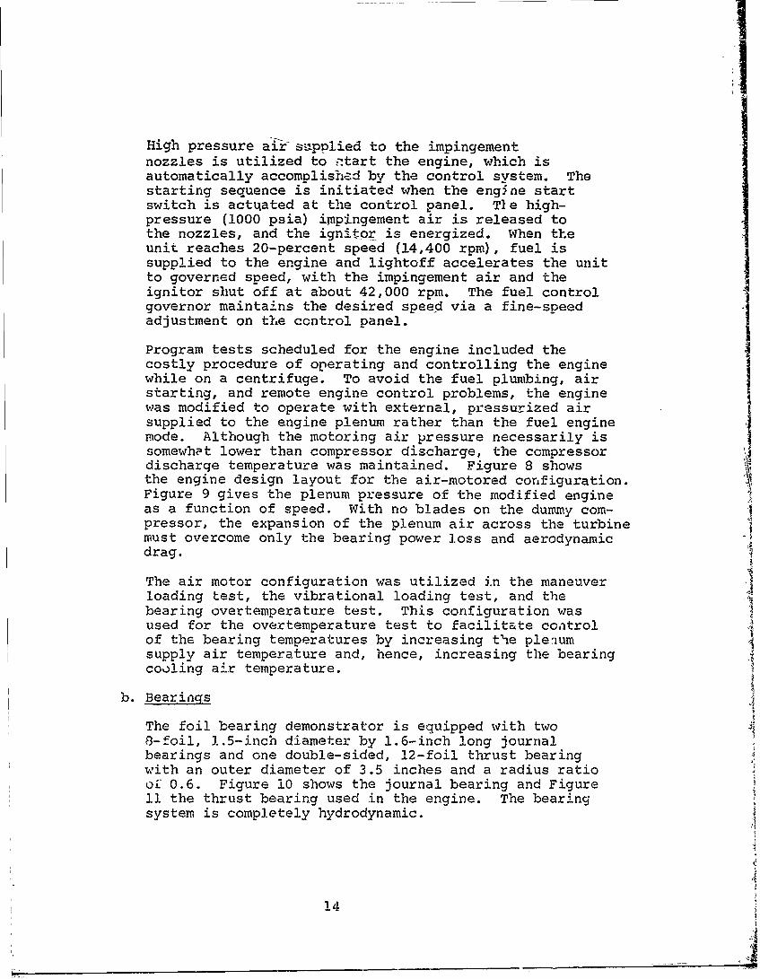
Program tests scheduled for the engine included thecostly procedure of operating and controlling the enginewhile on a centrifuge. To avoid the fuel plumbing, airstarting, and remote engine control problems, the engine
was modified to operate with external, pressurized airsupplied to the engine plenum rather than the fuel enginermode. Although the motoring air pressure necessarily issomewhat lower than compressor discharge, the compressordischarge temperature was maintained. Figure 8 showsthe engine design layout for the air-motored configuration. 4Figure 9 gives the plenum pressure of the modified engine
as a function of speed. With no blades on the dummy com-pressor, the expansion of the plenum air across the turbinemust overcome only the bearing power loss and aerodynamicdrag.
The air motor configuration was utilized in the maneuverloading test, the vibrational loading test, and thebearing overtemperature test. This configuration wasused for the overtemperature test to facilitate controlof the bearing temperatures by increasing the ple-iumsupply air temperature and, hence, increasing the bearingcooling air temperature.
b. Bearings
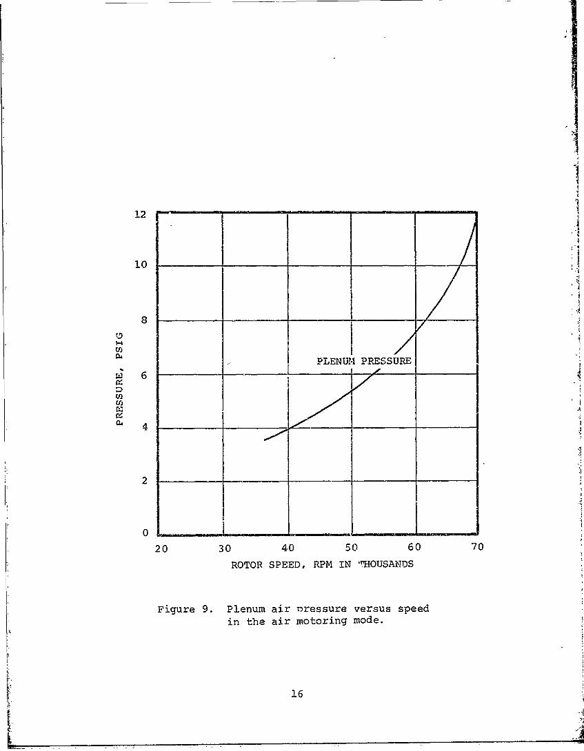
The foil bearing demonstrator is equipped with two8-foil, 1.5-inch diameter by 1.6-inch long journalbearings and one double-sided, 12-foil thrust bearingwith an outer diameter of 3.5 inches and a radius ratioor 0.6. Figure 10 shows the journal bearing and Figure11 the thrust bearing used in the engine. The bearingsystem is completely hydrodynamic.
14

cows~v~w'~ ~ OMUSTOR LIEIRDUCTr APTE? FLANGEVE
DUNIY IMPELLE3R
DIMSE REPACEDAIR MLOTORWIM r=IN Pl~A.ECOINFIGURATION
~> JET FUELCONFIGURATION
Figure 8. Changes to original foil bearing demonstrator forconversion to air motoring mode.
15
!2
10
8/
I-4
PLENUM PRESSURE
6
2
0!
20 30 40 50 60 70
ROTOR SPEED, RPM IN 'HOUSANDS
Figure 9. Plenum air oressure versus speed
in the air motoring mode.
16I' L4
Figure 10. Journal bearing selected forfoil bearing demonstration.
17

Figure 11. Thrust bearing set selected for foilbearing demonstrator.
18
NI- 74

Io
The foil coating utilized for both the tUrust and journalbearings is Teflon. Although it has a relatively lowtemperature limitationsthe Teflon coating has exhibitedlow friction and good embedment and wear-in charFcteris-tics which other candidate coatings were unable tomatch.
The foil bearing system relies on compressor dischargeair for pressurization and cooling. Higher air pressuresand temperatures generally will provide higher loadcapacity. At sea level conditicns, compressor dischargetemperature will reach 2800 to 320OF and will providecLoling to maintain the bearings at 4800 to 5250 F. Eachjourii3a bearing requires 0.004 pound per second coolingairflow and the thrust bearing requires 0.012 pound persecond per side.
The breakaway torque for the rotor/bearinr system isabout 12 inch-pounds. A Performance map !or the jour-nal bearings, established from test rig results in aprevious program, is included in Figure 12. Thebear-ing has a projected area of 2.4 square inches and,under good loading conditions, will generate about 10.5psi or 25 pounds under ambient test conditions. Thegyroscopic torque loading, combined with some degree ofmisalignment and thermal distortion unavoidable in anengine application, produced loads somewhat less thanthose obtained from the test rig, as indicated by thetest results reported in Section 4.
The load capacity for the thrust bearing was also es-tablished from test rig results in a previous programand is shown in Figure 13. The bearing has a projectedarea of 6.35 square inches and, under good loading con-ditions, will generate 25.3 psi or 160 pounds underambient test conditions.
The calculated aerodynamic thrust of the engine rotor ispresented in Figure 14 as a function of speed. Themaximum thrust is 30 pounds in the forward directionoccurring at full speed.
c. Instrumentation
Instrumentation was installed on the engine to monitorbearing performance and observe general engine aero-dynamic parameters to ensure proper iperation of Lheengine. Figure 15 shows the location of the engineinstrumentation.
19

0.16 --
0.14
-.10
00
0.0800o _~a4~o
40,Rp 2000 .z0 0.06
S~TSPEED, R PY. 20,0000.02
0i NOWNiiI - - - 2
Ficaure 12. Performance map for journal bearings.
20

.1
t
101
.014 - '- I--11
.0120
' \ _ _.-.._ _ I -_ _ ..
-VV '"_ A " OO (,
o \o
g 006
o~
o~o
S.004
.00AMBIENT PRESSURE 14.7 PSIA
• 002 -AMBIENT TEMPERATURE, 75 OF -
BEARING AREA, 6.34 SQ.IN.0
HI
0 _ _40 80 120 160 1200
BEARING LOAP, LBS
Figure 13. Load capacity of thrust bearing.
21

+ 4- 4 44r rr
* -4
t .viw A---r R~1 -Y .. i4
?O44-
I
7-t~
A T 4 iH 41L-
Figure 14. Aerodynamic thrust as a functionof speed.
22

CCY'PRESSOR DYSCHARGEPRESSV=- "'PEA-lVRE
7R'-UST .%GJOURNAL 3RG
TZIME PE VR \\ -RWR
PROXIMIT PROBES
4 RADI TURBINE IDISCFIARGE
INSTRUMENTATIONOUT
70JFigure 15. Engine instrumentation.
23
Wayne Kerr proximity probes were utilized to monitorshaft excursion. The probes were exposed to a tempera-ture environment of about 4000 F. Because of theirinsensitivity to temperature, Wayne Kerr probes were
chosen over other types of proximity probes.
Instrumentation readout and recording were accomplishedwith instruments appropriate for each test. Sanbornand Offner recorders were used generally to recordimportant engine aerodynamic data and bearing temperature.A tape recorder was utilized to record shaft excursion,the tape to be played back later through a Sanbornrecorder or an oscilloscope.
4. TEST PROGRAM
The test progra.i consisted of five tests, each necessary todetermine the feasibility of utilizing foil bearings on enginesrequiring qualification testing.
a. Water Ingestion Test
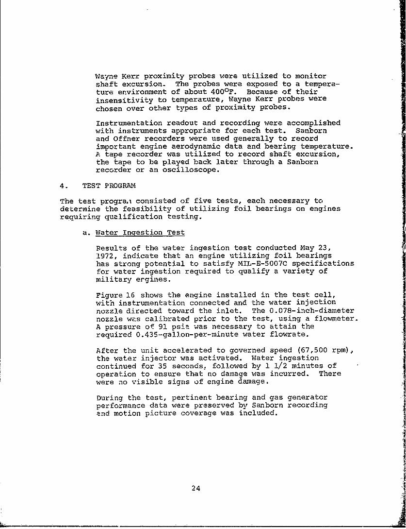
Results of the water ingestion test conducted May 23,1972, indicate that an engine utilizing foil bearingshas strong potential to satisfy MIL-E-5007C specificationsfor water ingestion required to qualify a variety ofmilitary ergines.
Figure 16 shows the engine installed in the test cell,with instrumentation connected and the water injectionnozzle directed toward the inlet. The 0.078-inch-diameternozzle was calibrated prior to the test, using a flowmeter.A pressure of 91 psia was necessary to attain therequired 0.435-gallon-per-minute water flowrate.
After the unit accelerated to governed speed (67,500 rpm),the water injector was activated. Water ingestioncontinued for 35 seconds, followed by 1 1/2 minutes ofoperation to ensure that no damage was incurred. Therewere no visible signs of engine damage.
During the test, pertinent bearing and gas generatorperformance data were preserved by Sanborn recordingand motion picture coverage was included.
24

v~ . -x
r ~ FZ,-N
W
Figure 16. View of water nozzle directed towardinlet of engine prior. to start of wateringestion test.
Fo.lowing the test, the unit was disassembled for bearinginspection and photography. Figure 17 shows a 10-powermagnification of typical journal bearing foil segments.Other than a slight polish from shaft contact duringstarting and stopping there were no signs of damage tothe bearings. Since the test was relatively short, thebearings did not reach high steady-state temperatures andthe foil coating did not darken.
Figure 18 shows a 10-power magnification of a typicalthrust bearing segment. Some scratches are evident, butthese were attributed to dust inadvertently introducedduring assembly. (Airborne dust entrained by the radiallyintroduced bearing cooling air would have produced ahelical scratch.) Local discoloration, common to allbearings as they "bed in", is evident, but as observed inprevious running no performance deterioration resulted.
b. Dust Ingestion Test
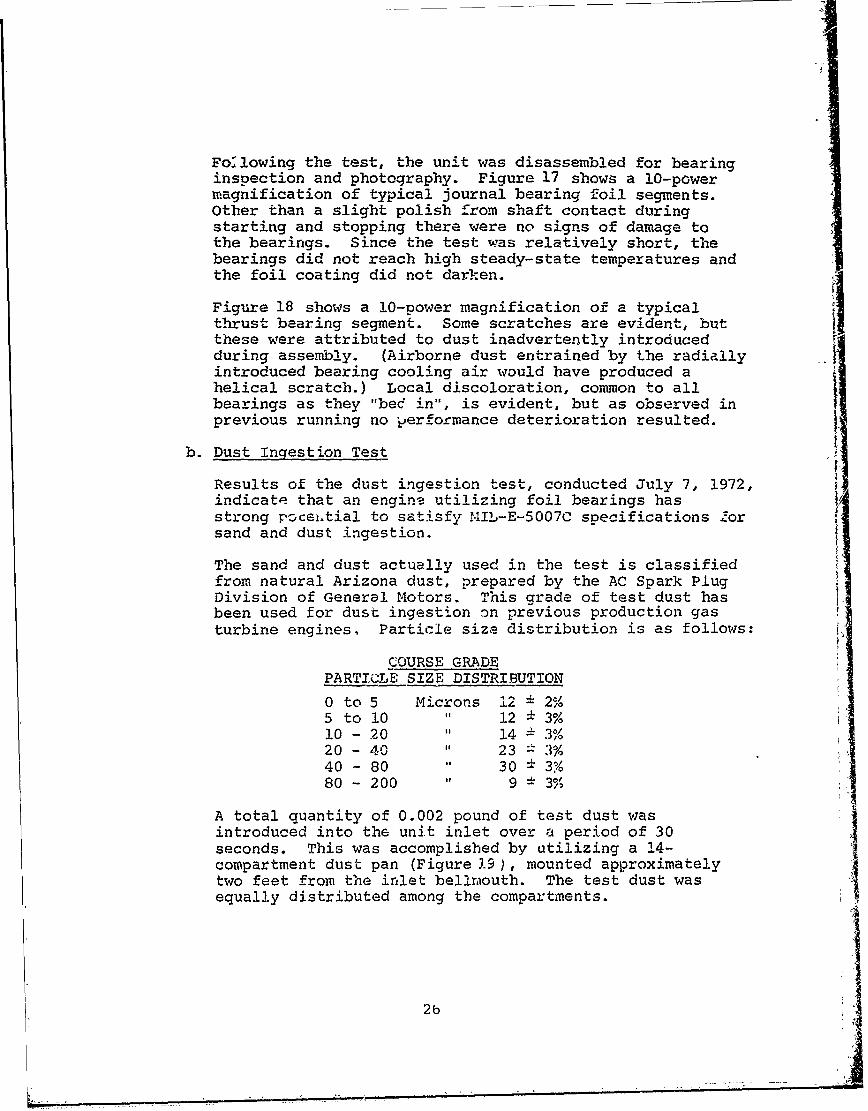
Results of the dust ingestion test, conducted July 7, 1972,indicate that an engine utilizing foil bearings hasstrong pz cei.tial to satisfy 14IL-E-5007C specifications forsand and dust ingestion.
The sand and dust actually used in the test is classifiedfrom natural Arizona dust, prepared by the AC Spark PlugDivision of General Motors. This grade of test dust hasbeen used for dust ingestion on previous production gasturbine engines. Particle size distribution is as follows:
COURSE GRADEPARTICLE SIZE DISTRIBUTION
0 to 5 Microns 12 2%5 toli " 12 3%10 - 20 " 14 3%20 - 40 " 23 3%40 - 80 30± 3?80 - 200 " 9 3%
A total quantity of 0.002 pound of test dust wasintroduced into the unit inlet over a period of 30seconds. This was accomplished by utilizing a 14-compartment dust pan (Figure 19), mounted approximatelytwo feet from the inlet bellraouth. The test dust wasequally distributed among the compartments.
2b

*41
Vft
-4-
27t

I
Figure 18. Ten-power magnification of forward thrustbearing foil segments after water ingestiontest.
MP- 3422728
-I .rAIR NOZZLE
Figure 19. Foil bearing demonstrator and dustingestion mechanism prior to dustingestion test.
MP-349,5L
29

An additional quantity was added to allow for thedust film which constantly remained in the dust pan.The pan was set far enough frem the unit inlet to preventthe test dust from being drawn into the inlet duringengine starting, prior to initiation of the test.
A time-interval energized linear actuator was used tomove an air nozzle past the dust pan compartments toblow dust from each of the compartments into the engineinlet during the 30-second period.
Before the actual test was initiated, a test run was made.The engine inlet was covered and dust was blown from thepan toward the inlet, establishing the direction of thespray and ensuring that all of the dust would be blownout within the required period. (All of the dust wasblown from the pan in 29.2 seconds.) With the inletcover removed, several engine starts were made for overallsystem checkout, after which the pan was refilled and thedust ingestion test was initiated.
With the engine operating at a governed speed of 67,500rpm, the required 4.4 x 10⁻⁵ pounds dust per poundthroughflow was introduced into the inlet for the 30-second period. The engine was operated for an additional150 seconds to ascertain whether any immediate effectson engine operation or performance would result. Nodeterioration in either was detected.
Following the test, the unit was disassembled forinspection. Figure 20 shows two sample journal bearingfoils: one from the turbine-end bearing and the otherfrom the compressor-end bearing. The foils were inexcellent co:zdition. Normal minor discoloration at thefoil tips' where they experience the greatest soakbacktemperatures (540°F in this test), and some glaze, whichaccompanies "bedding in", were evident. Shallow scratches,particularly the axial ones, could be seen on the foils.These may have been caused by trapped dust particlesbeing rolled along the foils as the shaft was withdrawnduring disassembly.
The forward and aft thrust bearing assemblies are shownin Figure 21. The circled portions of each, magnifiedten times, are shown in Figure 22. As with the journalbearing foils, both thrust bearing assemblies were inexcellent condition. Some of the dust particles wereembedded in the foil coatings; the rest of the dust seemedto have had little effect on the bearings, other thanleaving minor scratches. Some local charring was evidenton all of the bearings, as was noticed after the wateringestion test.
30

Non
-4-
Figure 20. Journal bearing foil segmentsafter dust ingestion test.
43

Figure 21. Forward and aft thrust bearingassemblies after dust ingestiontest.
MIP- 348'
32
p(
I
|I
Figure 22. Ten-power magnification of thrust bearingfoil segments after dust ingestion.
3I33
I
c. Maneuver Loading Test
Engine modifications as described in Paragraph 3 (a) weremade prior to the initiation of the maneuver load test.Because this test was to be performed on a centrifugetest rig, the demonstrator was modified to operate withexternal, pressurized air (air-motoring mode) rather thanthe jet-fuel mode.
The purpose of this test was to operate the demonstratorunder imposed loads from a 3.5-radians-per-second yawrate simultaneous with 5-a acceleration. The modifieddemonstrator, mounted in the centrifuge adaptor, is shownin Figure 23.
The required 3.5-radians-per-second yaw maneuver ratecombined with a 5-g centrifugal acceleration defines aunique centrifuge arm radius of 13.3 feet. Since thecentrifuge planned for use was limited to 10 feet, areduction in rotor speed from 67,500 to 52,000 rpm wasnecessary to provide a 3.5-radian equivalent gyroscopicload on the bearings.
The maneuver loading tests were conducted as follows.
1) Test No. 1
The original maneuver test was attempted August 23,1972 at the AiResearch-Phoenix facility. The demon-strator was positioned 10 feet from the center of thecentrifuge and waa operated at an engine speed of52,000 rpm. At approximately 11 rpm centrifuge speed,a noticeable drop in demonstrator speed was observed,followed by a partial recovery, another drop, a weakrise, and finally a decay to zero. The 1oss of hydro-dynamic gas film occurred at about 11 rpm centrifugespeed, resulting in 'ztghly increased drag and subsequentloss in rotor speed. This delay in speed, however,reduced the "gyroscopic load" (a product of rotor speedand induced yaw rate) by a sufficient degree that thebearings could reestablish a gas film at the then exist-in- rotor speed of 26,000 rpm. This, in turn, "freed"the shaft, allowing it to reaccelerate until the cyclewas repeated, finally resulting in sufficiently highfoil/shaft temperatures to cause total seizure.
3
34
-?-- -- -- - ---
Figure 23. Front view of modified foil bearing demonstratormounted on centrifuge adaptor prior to maneuverload test.
35

The decision to abort the run was made after the firstcycle, but the low gain of the centrifuge drive/brakeair-jet system, coupled with the high inertia of thearm, test piece, and counterweights, made it impossibleto stop the simulated yaw maneuver in time to save thebearings.
Following the test, the unit was disassembled forinspection. The compressor-end foils are shown inFigure 24, the turbine-end foils in Figure 25, and thejournal shaft/thrust runner assembly in Figure 26.Failure appeared to be the result of corner loadingthe bearings in excess of the load capacity that theycould hydrodynamically sustain under the test shaftspeed and bearing environment.
A number of bearing environment compromises, necessi-tated by the use of the 10-foot centrifuge, degradedthe bearing performance to a higher degree than antici-pated. These include the aforementioned reduction inshaft speed, bearing cavity pressure and inlet tempera-ture from those seen when the demonstrator is operatedin the jet-fuel mode.
It was decided, therefore, to repeat the test at theAiResearch facility at Mint Canyon, near Los Angeles,California. This is a new facility equipped with a20-foot centrifuge that can easily provide the requiredmotoring air supply up to 3500F. It also has an elabo-rate "brush" assembly that assures adequate signaltransmission from the rotating assembly to ground, withminimum noise and high reliability.
The damaged parts of the demonstrator were replaced inpreparation for the Mint Canyon maneuver test.
2) Test No. 2
After assembly, a bench test was conducted in Phoenixfor checkout prior to shipment to Los Angeles. Thebench test was conducted to accumulate informationabout the air motor configuration of the demonstrator,which was unobtainable while running on the centrifuge.
Static pressure taps were located at strategicpositions throughout the engine (Figure 27) to monitorpressures at various speeds. Figure 28 contains plotsof the pressures as a function of speed. The pressuredata indicate the flow rate and the paths taken by thecooling airflow. Figure 5, showing the direction of AI
flow of the cooling air and the approximate flow rate,was generated by the data from Figure 28.
36

!I
IIII
Figure 24. Compressor-end journal bearing foil segments Iafter maneuver load test (top of photographoriented toward front of engine, as installed).
MP.35510 37
.I

I1I,--fii
Figure 25. Turbine-end journal bearing foil segments aftermaneuver load test (bottom of photograph orientedtoward rear of engine, as installed).
MP-3 5"8
7::___ ___ ___ ___ ___ _ _ ___ ______ __38_

Figue 2. Jorna shat/trus runer ssemly fte
mar7e lodtet
MP- 355
39

3 PRES S URES
/ / 11 I I\\
2 3 5
TEMPERATURE S
Figure 27. Instrumentation locations in foil bearingdemonstrator.
40

t12
J . I I101
8
__- PLENUM PRESSUR'
PRESSURE AT LOCATION_ .,0. 3NO. 2-2 NO. 4"-0 '
NO .1 O , - - '' " - - ' - -
NO. 6-"
20 30 40 50 60 70
ROTOR SPEED, RPM IN THOUSANDS
Figure 28. Cooling airflow pressure distribution infoil bearing demonstrator.
41
Proximity probes were utilized in the bench test tomonitor shaft displacements and an oscilloscopemonitored radial displacements by displaying zlissajous pattern.
When the demonstrator was started, it quickly acceler-ated to a steady-state speed of 48,000 rpm. A preloadof 25 pounds was used for the thrust bearing, causingthe rollover torque to be 24 inch-pounds. The rela-tively high plenum-air pressure required for breakawayresulted in the 48,000 rpm steady-state speed.
The demonstrator was operated at 71,200 rpm for about10 minutes, until the bearing temperatures hadcompletely stabilized. The shaft appeared to be stableas the shape of the lissajous pattern remained rela-tively constant throughout the speed range.
The thrust bearing temperature climbed to 4600 F, thefront journal bearing to 4400 F, and the aft journalbearing to 3850F. It was felt that running the unitwith the thrust bearing at 500OF or above constitutedan unnecessary risk for the amount of potential addi-tional load capacity. Thus, the test was concludedand the plenum air supply (2900F) was terminated. The
unit rolled dcwn to zero speed in excess of 11 seconds.During this time, the bearings received no coolingairflow* and the indicated thrust bearing temperatureclimbed to over 5000 F. (Near the end of the rolldownand during the subsequent soakback period, thethermocouple was not suitably located to monitor thehottest part of the bearing, and it is estimated thebearing temperature was actually in excess of 6000 F.)The high preload on the thrust bearing coupled withthe 11-second loss of cooling flow al.lowed the bearing
temperature to exceed the coating limitation, resultingin part of the coating adhering to the shaft. Thedamage was discovered when a rcllover torque test wasattempted and it required more than 30 inch-poundtorque to rotate the shaft.
*This is not the case during a typical engine shutdown,however, where cooling air is continuously available,though in diminishing amounts, until the compressorstops rotating.
42
: i

When the unit was disassembled and inspected, it wasfound that both sides of the thrust bearing wereslightly damaged by overtemperature and some distresswas noted in the backing plates, suggesting thatfailure occurred at the end of the rol!down. Bothjournal bearings were still in excellent condition andwere left in the engine. The thrust bearing wasreplaced, and the preload was relieved somewhat to avalue of 19 pound4 resulting in a rollover torque of15 inch-pound. The unit was reassembled and shippedto Los Angeles.
3) Test No. 3
At the AiResearch Mint Canyon facility, the demonstratorwas mounted on the centrifuge as shown in the schematicof Figure 29. The unit was oriented to discharge theexhaust in the direction of rotation of the centrifuge.This direction was chosen because the fluid couplingdrive normally idles the centrifuge at 5 rpm, which wasconsidered rather high for this test. Using demonstratorthrust to load the fluid drive, the idle was reduced toabout 3 rpm; thus the test could be initiated at a lowercentrifuge speed. Figures 30 and 31 show the test setupand Figure 32 shows the instrumentation and control con-soles inside the remotely located blockhouse from whichthe test was monitored and controlled. An Offner 8-channel recorder was used to register the values of per-tinent parameters during the test and a closed circuittelevision was set up for visual monitoring of thecentrifuge,
The hot pressurized air supplied to the demonstratorwas delivered by an AiResearch Model GTCP85-291Auxiliary Power Unit (APU) with pressure and tempera-ture conditioning accomplished by a remotely controlledpressure-regulating valve and a water-to-air heatexchanger. The air flowed through an overhead, insul-ated duct to the pivot axis of the centrifuge, througha rotating swivel joint to the centrifuge arm duct,and then to the unit.
When the installation was complete and a final cali-bration of the recorder was made, the demonstratorwas accelerated to 30,000 rpm, using motoring airfrom the ground supply unit. The plenum air tempera-ture gradually increased as the insulated air duct
43

SOLENOID TOADJUST WATER
EXCHANGERRCH
85-291
375 *F.%- GAS TURBINE
AIR (BLEED AIR
PRESSUREREGULATOR
AIR-TO- VALVEWATERHEAT I
EXCHANGER
_ _ _ -iiINSULATED FOIL BEARINGAIR LINE DEMONSTRATOR
REMOTE C ONTROLLE/ NOZZLECENTRIFUGEDRUM "
R EMOTE CONTROLLED
BUICKENGINEAUTOMATIC
ITRANS.
Figure 29. Schematic diagram of foil bearing demonstratormounted in Mint Canyon centrifuge test facility.
44

454
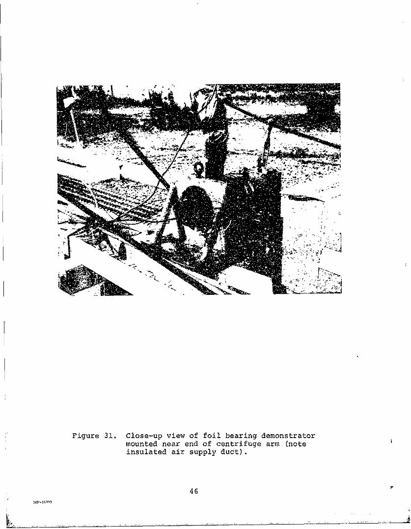
Figure 31. Close-up view of foil bearing demonstratormounted near end of centrifuge arm (noteinsulated air supply duct).
46
L3.A2

AA
Figure 32. View of centrifuge test instrumentationshowing centrifuge drive control, Of fner8-channel recorder, signal conditioner,and TV monitor.
47

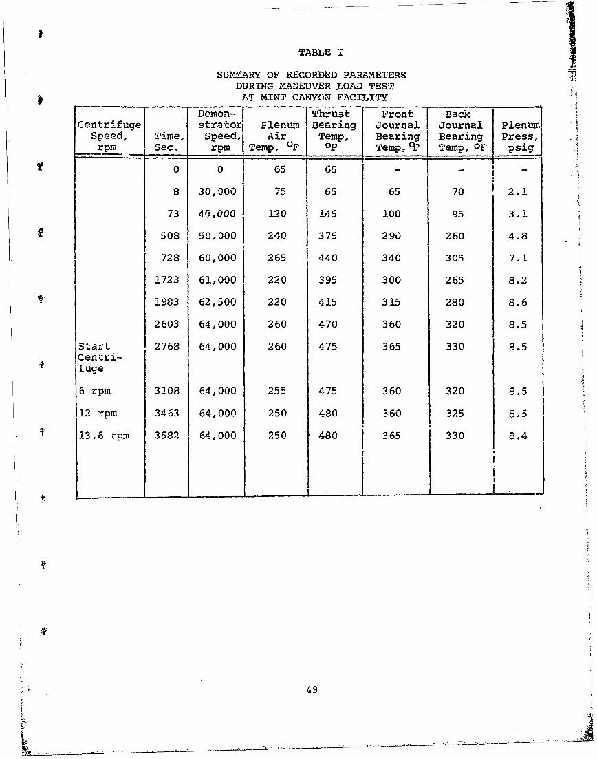
i.armed up, and the demonstrator speed stabilized at42,000 rpm at a plenum air temperature of 2600F.Table I sbcws the values of pertinent parametersmeasured at various time intervals and taken from theOffner recording. The total run timne of thedemonstrator was 59 minutes, 42 se,.onds. The maximumspeed of the demonstrator was 64,000 rpm. This speedwas limited bv the output pressure capability of theAPU, because a large pressure drop through the airduct and the swivel joint limited the availablepressure in the plenum to 8.0 psig.
The centrifuge was started, idled at 3 rpm, and thenthe speed was increased in increments of about 1 rpm.With the demonstrator oriented as shown in Figure 29,the compressor end of the rotating group was forceddown and the turbine end up due to the induced gyro-scopic movement. At a centrifuge speed of 13.6 rpm,the ultimate load capacity of the compressor-endjournal bearinq was exceeded. Shaft contact with thefoils resulted in a sharp rise in temperature, culmin-ating in seizure. The Offner recording of the lastseconds of the test is presented in Figure 33.
The demonstrator was returned to Phoenix where it wasdisassembled and inspected. The failure of thecompressor-end journal bearing was verified, but theturbine-end journal bearing was still in good condi-tion. The coating on both sides of the thrust bearingwas damaged from excessive heat, appearing somewhatlike the thrust bearing that underwent the checkoutbench test at Phoenix (Test 2). It is felt, however,that both these thrust bearings were damaged afterthe tests were completed, due to soakback of heatgenerated during the compressor journal bearingseizure, since neither the foil metal nor the backingplates displayed distress. Figure 34 shows both sidesof the thrust foil bearing and Figure 35 shows thecompressor side of the thrust runner. Figure 36 showsthe turbine-side of the thrust runner, along with theturbine end of the journal shaft, which was still inexcellent condition. The shaft was rigidly welded tothe compressor-end foils and bearing carrier and couldnot be pressed out of the carrier. Although a certainamount of welding of the foils occurred during otherbearing failures, the shaft could always be pressedout of the bearing carrier.
48
I
TABLE I
SUMMARY OF RECORDED PARAMETERSDURING MANEUVER LOAD TEST
*AT MINT CANYON FACILITY... .. Demon-i Thrust Front Back
Centrifuge strator Plenum Bearing Journal Journal Plen
Speed, Time, Speed, Air Temp, Bearing Bearing Press,rpm Sec. rpm Temp, OF OF Temp. 'emp, OF psig A
t 0 0 65 65 - - a -
8 30,000 75 65 65 70 2-1
73 40,000 120 145 100 95 3.1
508 50,300 240 375 290 260 4.8
728 60,000 265 440 340 305 7.1
1723 61,000 220 395 300 265 8.2
1983 62,500 220 415 315 280 8.6
2603 64,000 260 470 360 320 8.5
Start 2768 64,000 260 475 365 330 8.5Centri-fuge
6 rpm 3108 64,000 255 475 360 320 8.5
12 rpm 3463 64,000 250 480 360 325 8.5
13.6 rpm 3582 64,000 250 480 365 330 8.4
49
_ _ 1.

c-I
cI
C-4 t
81..
-TT.
7 A
~~1 4 -

Figure 34a. Forward thrust bearing surface.
Figure 34b. Aft thrust bearing surface.
51.MP-36883

Figure 35. Forward thruLt runner face.
52IMP-36885 5

ftL
t
sI
/'1:/- ;-I
2I
4I
1

in prior tests, however, the shaft outer surfaces had ahardness of Rockwell C-60 or better. For this test theouter surface hardness of t..e shaft was Rockwell C-40,and hence was less resistant to the tendency to "weld"than the other shafts.
Table II presents values of the pertinent parameters atthe time of bearing seizure.
TABLE 11
PERTINENT TEST INFORMATIONFROM PHOENIX AND MINT CANYON
MANEUVER LOAD TESTS
Phoenix Test Mint Canyon Test
Demonstrator speed, rpm 52,000 64,000
Terminal centrifuge speed, 11 13.6rpm
Centrifuge arm length, 120 158
inches
Rotor Ip, in.-lb-sec2 0.0138 0.01375
Rotor weight, lbs 4.88 4.86
Terminal-generated 86.61 131.7gyroscopic moment, in.-lb i
Terminal-generated 0.41 0.83centrifugal load, gsimultaneous withgyroscopic moment
In an effort to determine the load split between thejournal and thrust bearings, a force diagram of therotor was constructed as shown in Figure 37.
54

pX
8j T
LLR
II
(DT "m _ 4 R
P,, t L .,- R?
Figure 37. Analytic free-body of foil bearing demonstratorrotating group.
55

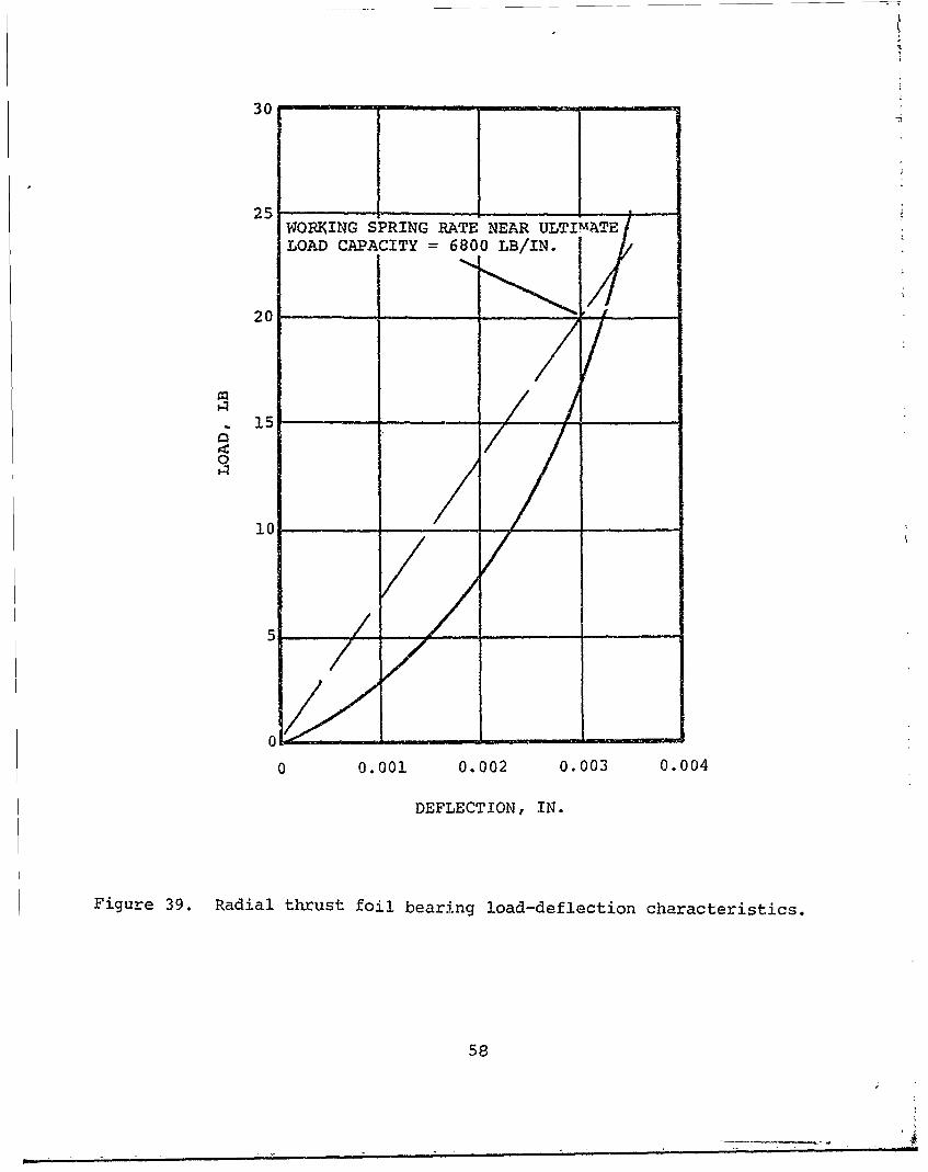
Before forces could be defined, however, load/deflection curves for both the thrust and journalbearings were required. These are presented inFigure 38 for the thrust bearing and Figure 39 for thejournal bearing. The thrust bearing springrate wasgenerated, assuming a 19-pound preload. There are 12nonlinear springs on each side of the thrust bearing,but only half are effective for resisting momentloading. The amount of preload on the springs affectsthe load/deflection curve and is representative of apurely axial load, equal on both sides of the bearing.
From Table II, the imposed gyroscopic moment on therotating group was 131.7 inch-pounds. Using a cal--culated aerodynamic thrust of 30 pounds acting forwaidon the rotating group, solutions of force and equi-librium equations yield the average loads on the thrustand jcurnal bearings. The solutions are shown inTable III, which indicates the loads on each bearingresulting from the gyroscopic torque, g-loading, andaerodynamic thrust. The last row indicates the totalunit loading on the bearings resulting from thecombined loading. Figure 40 is an isometric view ofthe shaft with the direction and magnitude of eachsource of loading. Of the 131.7 inch-pounds of torquegenerated, the thrust bearings resisted 61.96 inch-pounds or about 47 percent and the journal bearingsresisted 69.74 inch-pounds or about 53 percent of theload just before the load limit of the compressorjournal bearing was exceeded.
The average unit load capacities are lower by about15 percent than those predicted by test rig loadcapacity data, since the following engine phenomenawere omitted in the accumulation of the data.
The demonstrator incorporated thrust and journalbearings, both of which carried relatively equal andheavy moment loads, meaning that both of theiralignments and orthogonalities had to be held insteadof just those of the journal bearing, as in the caseof a journal bearing test rig.
Also, precautions are taken on a test rig to maintaina symmetrical load profile for the bearings and tostrive for maximum magnitude of the entire bearinglength. Misalignment, angularity, and unsymmetricalloading are avoided during bearing performance tests toobtain repeatable data. When the bearings resist animposed moment on the shaft, the shaft assumes askewed position relative to the bearings as shown(exaggerated) in Figure 41.
56

120
100
80
60Q:
0
20
0
0 0.001 0.002 0.003 0.004
DEFLECTION, IN.
Figure 38. Axial thrust foil bearing load-deflectioncharacteristics.
.57
30
25WORKJING SPRING RATE NEAR ULTIMATELOAD CAPACITY = 6800 LB/IN.
20
15
10
10
0 0.001 0.002 0.003 0.004
DEFLECTION, IN.
Figure 39. Radial thrust foil bearing load-deflection characteristics.
58

TrIRUST LOADFPROm IMPOSEDGRYOSCOPICIMOELADFMTORQUE 21.52 LB CMEIUA LACERO TIO IMPOSED LOAD FROM
CENTIFUGL ACELERTIONGYROSCOPIC TORQUE
AERO THRUST \11-6LREACTION 13LOAD 7.6 LB
ROTOR WEIGHTREACTION LOAD= 1.65 LB
A 80 HRUSTTHRUST LOAD30 LB FROM1 IMPOSEDAERO THRUST
CYROSCOPICREACTION TOQE=2.2LLOAD 7.5 LB
41 ROTOR WEIGHT =4.86 LB
IMPOSED LOAD FROMGYROSCOPIC TORQUE
---- ROTOR WEIGHTREACTION LOAD
z3.21 LB
Figure 40. Isometric diagram of imposed loads- uponcompressor journ~al bearing seizure.
59

TABLE III
RESULTS OF BEARING FORCESAND AVERAGE LOAD
CARRIED BY EACH BEARINGJUST BEFORE LOAD CAPACITY OF COMPRESSOR
JOURNAL BEARING WAS EXCEEDED DURINGMINT CANYON MANEUVER TEST
(LOADS SHOWN PICTORIALLY IN FIGURE 40)
Bottom Top MiddleCompressor Turbine Turbine Compressor SectionJournal Journal Thrust Thrust Thrust
Parameter Bearing Bearing Bearing Bearing Bearing
Load due to gyro 17.56 17.56 21.52 21.52torque (lb)
Average unit load from 7.32 7.32 13.49 13.49gyro torque (psi)
Load due to rotor 3.21 1.65 ---
weight (lb)
Average unit load from 1.34 0.69rotor weight (psi)
Load due to centrifugal 2.66 1.37"g" forces (lb)
Average unit load from 1.11 0.57centrifugal "g"forces (psi)
Load due to aero- 7.50 i 7.50 15.00dynamic thrtist (lb)
Average unit load, due 4.70 4.70 4.70to aerodynamicthrust (psi)
Resultant load (lb) 20.94 15.97 14.02 29.02 15.00
Resultant average unit 8.73 6.65 8.79 18.20 4.70load (psi)
The loss of capacity in the bearing thus became a measure of its compli-ancy, or self-aligning capability. The skewed position of the shaft,when resisting a moment loading, decreases the effective area in thebearing that can generate the maximum load capacity. Hence the bearingdemonstrates less overall load capacity than is observed in test rigdata.
60
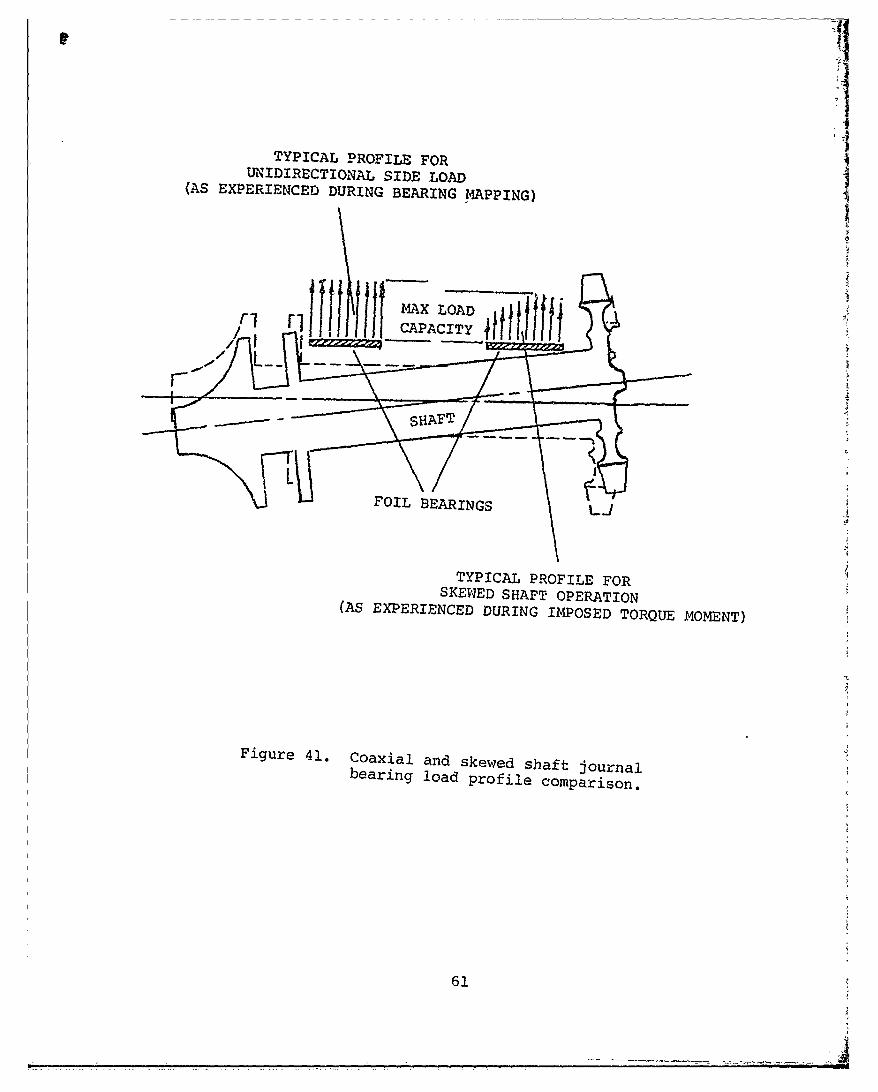
TYPICAL PROFILE FORUNIDIRECTIONAL SIDE LOAD
(AS EXPERIENCED DURING BEARING MAPPING)
MXLOAD
- SHAFT
FOIL BEARINGS
TYPICAL PROFILE FORSKEWED SHAFT OPERATION(AS EXPERIENCED DURING IMPOSED TORQUE MOMENT)
Figure 41. Coaxial and skewed shaft journalbearing load profile comparison.
61
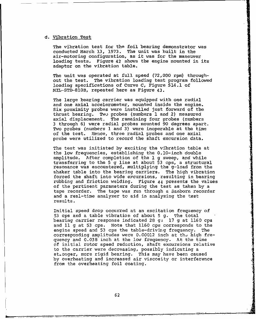
d. Vibration Test
The vibration test fof the foil bearing demonstrator wasconducted March 13, 1973. The unit was built in theair-motoring configuration, as it was for the maneuverloading tests. Figure 42 shows the engine mounted in itsadaptor on the vibration table.
The unit was operated at full speed (72,000 rpm) through-out the test. The vibration loading test program followedloading specifications of Curve C, Figure 514.1 ofMIL-STD-810B, repeated here as Figure 43.
The large bearing carrier was equipped with one radialand one axial accelerometer, mounted inside the engine.Six proximity probes were installed just forward of thethrust bearing. Two probes (numbers 1 and 2) measuredaxial displacement., The ramaining four probes (numbers3 through 6) were radial probes mounted 90 degrees apart.Two probes (numbers 1 and 3) were inoperable at the timeof the test. Hence, three radial probes and one axialprobe were utilized to record the shaft excursion data.
The test was initiated by exciting the vibration table atthe low frequencies, establishing the 0.10-inch doubleamplitude. After completion of the 1 g sweep, and whiletransferring to the 5 g line at about 53 cps, a structuralresonance was encountered, multiplying the g-load from theshaker table into the bearing carriers. The high vibrationforced the shaft into wide excursions, resulting in bearingrubbing and friction welding. Figure 44 presents the valuesof the pertinent parameters during the test as taken by atape recorder. The tape was run through a Sanborn recorderand a real-time analyzer to aid in analyzing the testresults.
Initial speed drop occurred at an excitation frequency of53 cps and a table vibration of about 5 g. The totalbearing carrier response indicated 28 g: 17 g at 1160 cpsand 11 g at 53 cps. Note that 1160 cps corresponds to theengine speed and 53 cps the table-driving frequency. Thecorresponding amplitudes were 0.00012 inch at th, high fre-quency and 0.038 inch at the low frequency. At the timeof initial rotor speed reduction, shaft excursions relativeto the carrier were decreasing, possibly indicating ast.onger, more rigid bearing. This may have been causedby overheating and increased air viscosity or interferencefrom the overheating foil coating.
62
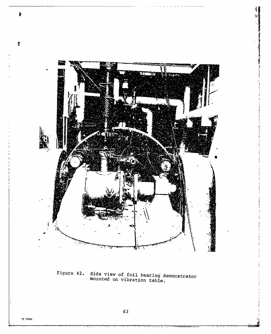
Figure 42. Side view of foil bearing demonstratormounted on vibration table.
63
435 37980

0. 1& 010 IN~CH D.A.
cRQENY 6,pL
44,

* ~- - *1
~~j__
---I .Ailhi_~TM
_r
1r,1
9 p E
E4 4
*~' ,t0+ i0o * -
Id U>4L-
F~gre44.Osilorp reodn ofvbain;st
65 J a -

After the test, the unit was disassembled and inspected.The compressor journal bearing had failed and the foilswere inertia-welded into the shaft. The remaining bear-ings, however, were in relatively good condition. Nodamage was incurred by the turbine or other parts of theunit except for the foils, the immediate bearing carrier,and the shaft.
Figure 45 shows the shaft as it came out of the engine.Slight residual damage is visible at the turbine bearingend of the shaft, which probably occurred after the frontbearing failed and the shaft experienced large displace-ments. Slight damage is also visible at the inner diam-eter of the turbine thrust bearing, which is adjacent tothe failed journal bearing where high temperature soakbackdamaged the foil coating.
Figure 46 shows the remaining turbine journal bearingwhich is in relatively good condition although parts ofthe foil coating were scuffed. The bearing did not over-heat and, from the color of the foil coating, did not ex-perience temperatures above 500'F.
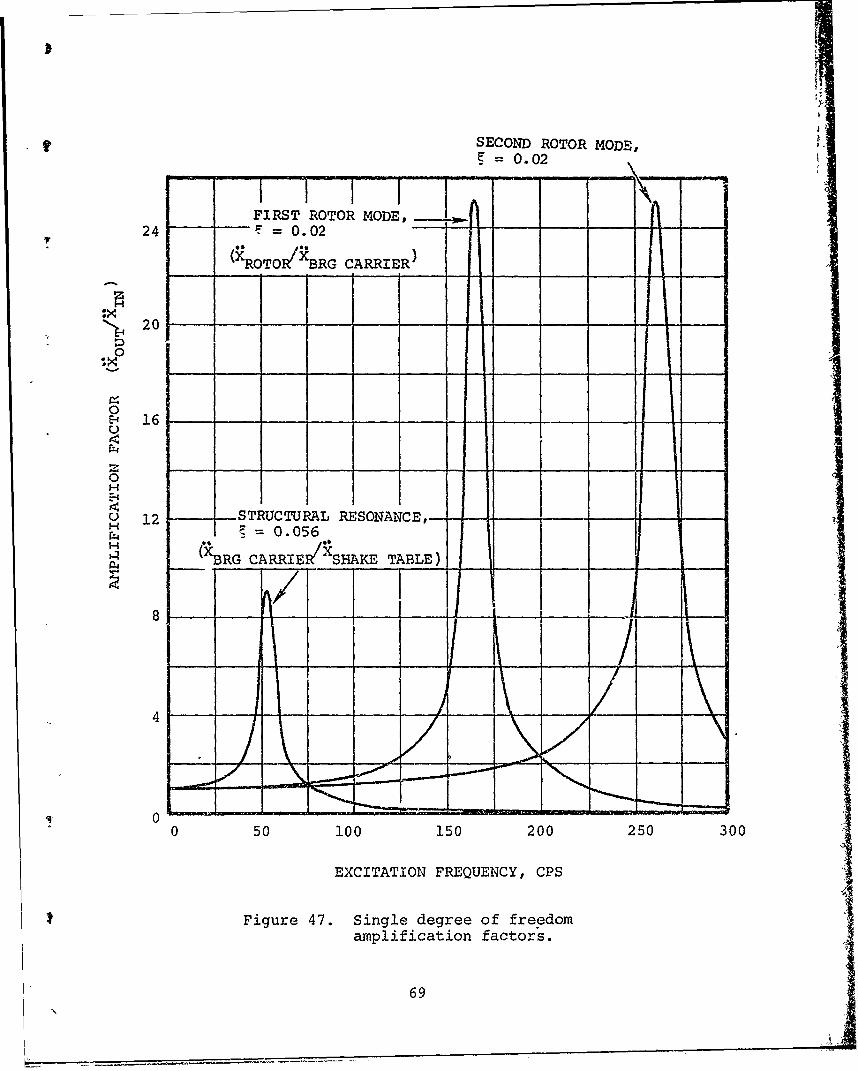
A renewed critical speed analysis was conducted with thebearing springrates increased to 10,000 lb/in. rather than5000 lb/in, used in the previous analysis presented inFigure 47. The nea springrate was considered to be morerealistic in view of the high shaft displacements involved.The resulting critical speeds were 166 cps (9970 rpm) and262 cps (15,700 rpm). Figure 48 shows the amplificationfactors in a simplified single degree of freedom systemwith the above natural frequencies. The structural re-sponse was detected from the data of the vibration test.The rotor resonances were predicted from the criticalspeed analysis. Using the data from Figure 2, Figure 3was generated to show the amplification factor of therotor with respect to the shaker table. The peak ampli-fication factors are 9.0, 2.9, and 1.1. The high reduc-tion of the two rotor resonances (critical speeds) resultsfrom isolation by the structure. This leads one to be-lieve that the structural resonance of 53 cps at thebearing carrier is the worst vibrational loading conditionfor the bearings, had the unit survived the entire vibra-tional scan. However, there may be other structuralresonances which more closely match the rotor criticalspeed frequencies, not providing the isolation shown inFigure 3. A problem such as this would require develop-ment to "tune" the structural frequencies away fromcritical speed frequencies.
66

It
Figure 45. View of shaft and two thrust bearingsafter disassembly upon comlpletion ofvibration test.
67MP-3 7978
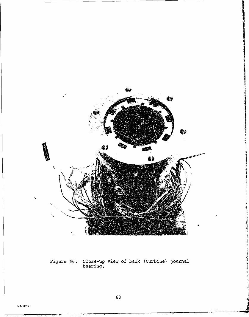
Figure 46. Close-up view of back (turbine) journalbearing.
68
MP-37979
SECOND ROTOR MODE,= 0.02
FIRST ROTOR MODE, 24 =0.02
(XROTOIX"BRG CARRIER )
201
0
E- 16 -UI
0H
U 12 -- STRUCTURAL RESONANCE,~ -
0O.056( BRG CARRIER SHAKE TABLE)
8" - - - It
4
- -
50 100 150 200 250 300
EXCITATION FREQUENCY, CPS
Figure 47. Single degree of freedomamplification factors.
69

A.MPLlFICATIO: FACTOR OJF
ROTOR WITH RESPECT TOTHE BEARING CARRIER
20 __- _ _
~16__ - ____i
0HE-4
~12______
AMPLIFICATION FACTOR OFP4ROTOR WITH RESPECT TO --
THE SHAKE TABLEf
4
04
0 50 100 150 200 250 300
EXCITATION FREQUENCY, CPS
Figure 4V. Estimated system amplification factors.
70

Structural frequencies in the engine, which can multiplythe g-loading to the bearings occur on many engine struc-tures and can become a development problem independent ofthe rotor/bearing natural frequencies. The originalJFS100-13A utilizes a relatively thick-walled plenum. madefrom a magnesiim casting. The plenum used on the foil 5bearing demonstrator was made from Type 321 stainlessstee and had a much thinner wall than its cast product.oncounterpart. The thinner wall consequently would exhibitsharper natural frequencies, with greater deflection andless damping.
It is believed that two phenomena caused the forwardjournal bearing to seize before either of the otherbearings. The first is that the centroid of the rotatinggroup is axially located closer to the forward journalbearing than to the aft journal bearing. Secondly, thevibrational load path on the engine structure startswhere the engine plenum is bolted to the vibration fix-ture. The plenum amplifies the input vibration withminimum displacement of "pivoting" at the installationlocation, which is just ahove the turbine wheel and veryclose to the aft journal bearing.
Thus, the maximum vibrational loading occurred on thefront, not on the aft, journal bearing.
71

e. Foil Bearing Overtemperature Test
The demonstrator, with new bearings installed, wasassemibled into the air motor configuration used formaneuver-loading and vibrational-loadinq tests. Thethrust bearings were preloaded to 14 pounds, approximatelythe preload used on the maneuver and vibration tests.
The measured breakaway torque was 16 inch-pounds, whichindicated a rather high preload, similar to that of themaneuver test. A check was made on the journal bearingalignment by inserting a bushing tool with an outsidediameter of 1.507 inches (0.007 inch larger than theengine shaft) through both journal bearings. Since itwas necessary to rotate the tool to be able to insert itthrough the bearings, it was evident that the bearingswere "bottomed out" and that the total sway space was0.007 inch.
The proximity probes used on previous tests were removedfrom the engine at assembly to preclude the possibilityof damage from either overtemperature or shaft rubbingat the time of bearing seizure, since, for this test, theIbearings were to be operated at incrementally hottertemperatures until bearing seizure occurred.9LBecause the thrust bearing temperature could be measuredmuch more accurately than the journal bearing temperature,it was decided to "overtemp" the thrust bearing.
72
9 -

Temperature measurements previously made on the journalbearings were actually a measurement of the bearingcarrier, since the bead of the thermocouple was locatedflush with the inside diameter of the carrier at thecenter of the bearing, beneath the foil. It was feltthat in this location the thermocouple was reading the Itemperature of cooling air flowing axially through thebearing, thus influenced by the plenum air and not pro-viding as accurate a recording of the foil or coatingtemperature as could be obtained from the thrust bearing.Further attempts at measuring the foil tenperature of thejournal bearing were successful but it was felt that themethod devised could impair the proper operation of the
bearing and more development was required to perfect themethod.
The thermocouple bead in the thrust bearing, however, isnot necessarily at the hottest operational part of thebearing. It is recognized that bearing surfaces otherthan that at the thermocouple bead can be hotter, dependingon bearing operation. For instance, in the Los Angelesmaneuver test the thrust bearing temperature was measuredin the same manner as in the overtemp test. With theverification test complete, all cooling (plenun) air wasshut down and the thrust bearing operating temperature wasrecorded at 4800F. The thrust bearing had absorbed arelatively large amount of rotor kinetic energy in a shorttime ( usually less than one second), especially whentouchdown occurred and bearing friction was greatlyincreased. During rolldown, thrust bearing recordedtemperature rose from 480OF to 505 0 F, a temperatureconsidered safe for Teflon coating. Since there wereno engine parts hotter than the bearings (the enginewas in the air motor configuration), no soakback problemsexisted and the 505°F was the highest recorded tempera-ture on the bearing.
Howevcr, after the bearings cooled, a rollover torque testwas attempted on the rotating group, and the torque wasfound to be much greater than was measured prior to theverification test. Upon disassembly, it was found thatparts of the thrust bearing foil coating had adhered tothe thrust runner and it was evident that the coating hadexperienced temperatures beyond 6000F, which is consideredthe absolute temperature limitation of the foil coating.Hence, for the rolldown torque test, the thermocouple didnot register the hottest parts of the bearing.
73i " 1

The small thermocouple, installed in the thrust bearing asshown in Figure 49 (as located in the overtemperaturetest), indicates temperature by air convection from thecentral part of the bearing. Temperature influence isobtained from the swirling air that is leaving the bearingand which has been heated from the constant viscousshearing inside the bearing. Due to high air speed, theconvection (heat transfer) rate is expected to be high,and the temperatures indicated by the thermocouple shouldbe approximately the same as those in the center of thebearing. During shutdown, however, and near the end ofshaft rotation, air speed, and therefore convection, islow and the temperatures at the thermocouple are lowerthan the maximum temperatures generated in the bearing.
After assembly, the engine was installed in a test cell(see Figure50) capable of providing temperature-controlled air at flows up to 110 pounds per minute.A 6-channel Sanborn recorder was used to monitor andrecord the pertinent bearing and engine parameters.
At a reference time "zero", cool, external pressurizedair was delivered to the engine plenum, resulting in abreakaway speed of 34,500 rpm. Table IV gives the valuesof pertinent parameters as a function of the referencetime taken from the Sanborn recorder traces.
After the engine and bearings had operated at the break-away speed for several minutes, the plenum pressure wasgradually increased until 50,000 rpm was achieved. Atthis speed, a hot air line was opened, increasing thetemperature of the air to the plenum. The hot airtemperature was 600°F and the desired air temperature tothe plenum was effected by mixing in an amount of hotair to the plenum feed line, which normally providedcold ai: (600F). The temperature regulation was accom-plished by means of a remotely cont-rolled solenoid valve.
After the delivery air temperature was increased to 260OFand it was verified that fine control of the aix tempera-ture was possible, the plenum pressure was increased untilthe unit reached the required speed of 70,000 rpm. Theunit speed was maintained at 70,000 rpm for the remainderof the test by decreasing the plenum air pressure wheneverthe temperature was increased. The delivery air tempera-ture was increased slowly until the thrust bearingindicated temperature reached 545 0F. (A goal of 550°F wassought but a L50F tolerance was as close as could bereasonably controlled.) The contractual 10-minute over-temperature of the bearing at 550OF (actually 5450F) was
74

r|
Figure 49. Thrust bearing thermocouple location.
75

Figure 50. Front view of foil bearing demonstratorinstalled in the overtemperature testfacility.
76 $
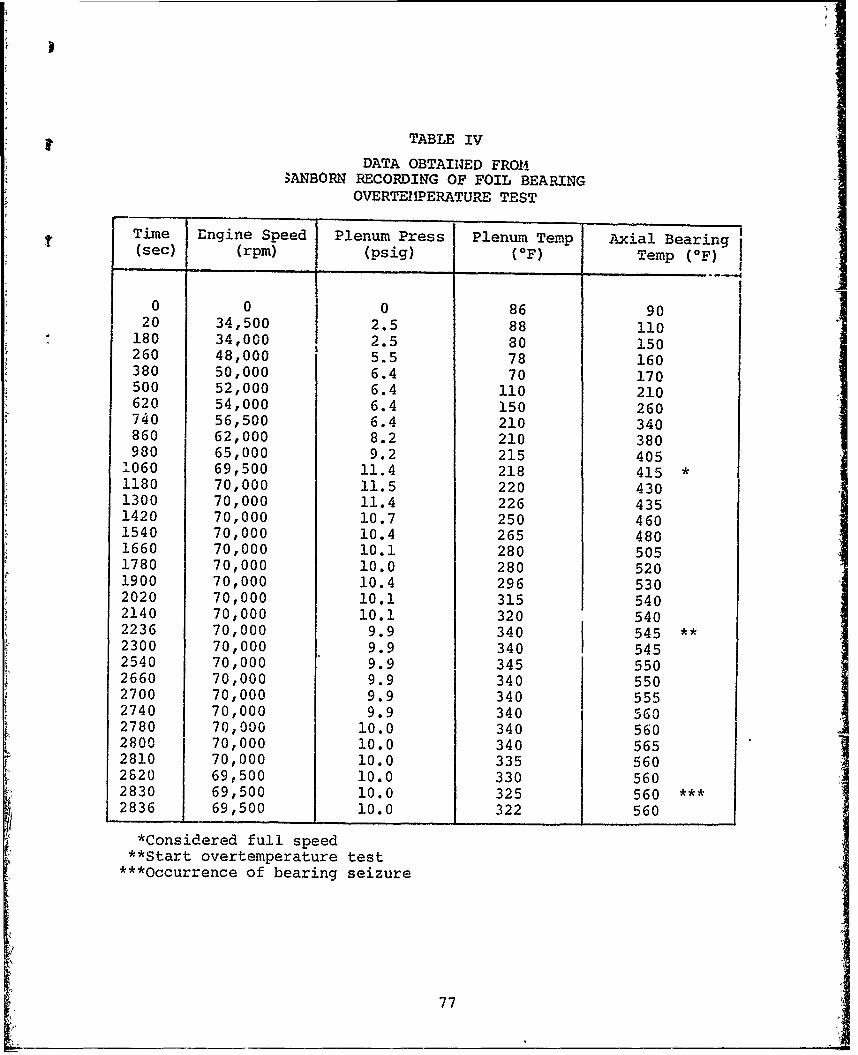
TABLE IV
DATA OBTAINED FRO4ANBORN RECORDING OF FOIL BEARING
OVERTEIDERATURE TEST
Time Engine Speed Plenum Press Plenum Temp Axial Bearing(sec) (rpm) (psig) (OF) Temp (OF)
0 0 0 86 9020 34,500 2.5 88 110
180 34,000 2.5 80 150260 48,000 5.5 78 160380 50,000 6.4 70 170500 52,000 6.4 110 210620 54,000 6.4 150 260740 56,500 6.4 210 340860 62,000 8.2 210 380980 65,000 9.2 215 405
1060 69,500 11.4 218 415 *1180 70,000 11.5 220 4301300 70,000 11.4 226 4351420 70,000 10.7 250 4601540 70,000 10.4 265 4801660 70,000 10.1 280 5051780 70,000 10.0 280 5201900 70,000 10.4 296 5302020 70,000 10.1 315 5402140 70,000 10.1 320 5402236 70,000 9.9 340 545 **2300 70,000 9.9 340 5452540 70,000 9.9 345 5502660 70,000 9.9 340 5502700 70,000 9.9 340 5552740 70,000 9.9 340 5G02780 70,000 10.0 340 5602800 70,000 10.0 340 5652810 70,000 10.0 335 5602620 69,500 10.0 330 5602830 69,500 10.0 325 560 *2836 69,500 10.0 322 560
*Considered full speed*Start overtemperature test
***Occurrence of bearing seizure
77

initiated at the reference time of 2236 seconds. (Theunit had been operated for 2236 seconds prior to theinitiation of the 550OF "overtemperature" test.)
As can be seen from Table IV, a plenum temperature of340OF and a plenum pressure of 10 psig were required tomaintain unit speed at 70,000 rpm and thrust bearingtemperature at 5500F. During approximately the last halfminute of operation, the bearing heat generation increased,which increased the temperature of the bearing. In aneffort to reduce the temperature to 5500F, the deliveryair temperature was reduced. This continual reductionresulted in a slight drop in unit speed and maintained thebearing temperature at 5600F. Other than the increase inbearing temperature, there was no warning prior tobearing seizure. The bearings operated in the 550OF hightemperature environment for 600 seconds. Figure 51 showsthe Sandborn trace at the end of bearing seizure.
After the test, the engine was disassembled and the
bearings inspected. Both sides of the thrust bearingwere discolored and the foil coating was dissipated,
indicating overtemperature conditions. As in other
bearing seizures, the shaft was welded to the foils, w;.thdamage sustained by both. No other engine componentsexperienced rubs or damage and all parts except the foils
and the spacer shaft were reusable without rework.
Figure 52 shows the forward thrust foil bearing afterdisassembly.
The mode of failure in the overtemperature conditionbegan with the Teflon coating, which decomposes afterreaching temperatures of 6000F. The gas given off bythe Teflon will cause no harm and will be swept awayfrom the bearing in the cooling airstream. There arecooler areas in the bearing, however, that will emitrelatively large quantities of a decomposed Teflonpowder, which acts as a bearing contaminant, like dirtand dust. This buildup of Teflon contaminant eventuallydisrupts the air film enough that the bearing cannotsupport the required load and it thl shatt,causing simultaneous increase in temperature and bearingseizure.
78

i I 7
PLW sPRURE - - -
rOX f -:1
I-
OUT I
-7 1
IT,,
L
-T U ,-PI
I1 T I
F'igure 51. Sandbogn trace showeing final seconds uf OVartemperature toot.
79

I'tqurto 52 View of forward thrust foilbe~aringj after disassembly.
80
MP 114

The need for coatings that are tolerant to temperaturesgreater than those in this test is evident. Research inthe development of pivoted-pad bearings has shown thepossibility of acquiring coatings that will withstandup to 12000 F. The two most promising materials appearedto be chrome-oxide for operation up to 800oF and nickel-chrome/chrome oxide for operation up to 12000F. Althoughnot exhibiting the desirable embedment characteristicsought in the foil bearing development, these candidatematerials are being considered for higher temperatureoperation capability.
81

SECTION III
CONCLUSIONS AND RECOMMENDATIONS
From the rssults of the program, it is concluded that the gas-lubricated foil bearing is a potential candidate for incorporationin advanced gas turbine engines. During the program, no problemswere encountered in operating the demonstrator at the full speed of72,000 rpm and the engine was impervious to the dust and waterinjected into the inlet.
Although no problem was encountered in operating the demonstratorengine at full speed, the maneuver test results indicated that anincrease in foil bearing load capacicy is desirable. While largerbearings and longer journal bearing spans eould be utilized toaccomodate greater yaw maneuver rates, the journal bearing dia-meters are cften limited by flowpath restrictions and excessivesurface speeds. To achieve yaw maneuver rates specified inMIL-E-5007A (3.5 radians per second), the load capacity of the foilgas-lubricated bearings must be increased.
Results of the vibration test reflect largely upon the engineframe rather than the bearings. Aircraft installations requirethat the engine frame prevent multiplication of vibrationalamplitudes from the source to the bearing carrier by provisionsfor adequate damping. Hence, results of the vibration test donot effectively evaluate the bearings, since many simultaneousconditions contribute to the vibrational characteristics of theengine.
The overtemperature test reveals that an ultimate temperature of550°F for the bearings is adequate for low-pressure-ratio enginesand other machines that utilize cooler air. The present foilcoating prevents higher temperature operation; hience the needfor higher temperature coatings is evident.
In summary, the program has shown that gas-lubricated foilbearings have encouraging potential and offer attractive advan-tages for application in advanced gas turbine engines.
There are two areas where further development is required, namely:
* The load capacity of the bearings must be increased tosupport loads induced by MIL-E-5007C maneuver specifica-tions.
A higher temperature coating must be developed for bearingapplication in larger, hiigher pressure-ratio engines.
82

Tt if. recommcnded that tbe foil bearing demonstrator be mountedon the wing of an aircraft and subjected to a -.ide variety ofmaneuvers, altitude operation, and vibrational environment that Iwould be representative of an actual aircraft-mounted engine.Observing the bearings under these conditions will further justifytheir general feasibility for small gas turbine application.
83
83