Distance Protection in Distribution Systems: How It Assists With ...
14
Distance Protection in Distribution Systems: How It Assists With Integrating Distributed Resources Amy Sinclair and Dale Finney Schweitzer Engineering Laboratories, Inc. David Martin and Pankaj Sharma Hydro One Networks, Inc. © 2012, 2013 IEEE. Personal use of this material is permitted. Permission from IEEE must be obtained for all other uses, in any current or future media, including reprinting/republishing this material for advertising or promotional purposes, creating new collective works, for resale or redistribution to servers or lists, or reuse of any copyrighted component of this work in other works. This paper was presented at the 2013 IEEE Rural Electric Power Conference and can be accessed at: http://dx.doi.org/10.1109/REPCon.2013.6681852. This paper was previously presented at the 65th Annual Conference for Protective Relay Engineers and can be accessed at: http://dx.doi.org/10.1109/CPRE.2012.6201231. For the complete history of this paper, refer to the next page.
Transcript of Distance Protection in Distribution Systems: How It Assists With ...

Distance Protection in Distribution Systems: How It Assists With Integrating
Distributed Resources
Amy Sinclair and Dale Finney Schweitzer Engineering Laboratories, Inc.
David Martin and Pankaj Sharma Hydro One Networks, Inc.
© 2012, 2013 IEEE. Personal use of this material is permitted. Permission from IEEE must be obtained for all other uses, in any current or future media, including reprinting/republishing this material for advertising or promotional purposes, creating new collective works, for resale or redistribution to servers or lists, or reuse of any copyrighted component of this work in other works.
This paper was presented at the 2013 IEEE Rural Electric Power Conference and can be accessed at: http://dx.doi.org/10.1109/REPCon.2013.6681852.
This paper was previously presented at the 65th Annual Conference for Protective Relay Engineers and can be accessed at: http://dx.doi.org/10.1109/CPRE.2012.6201231.
For the complete history of this paper, refer to the next page.

Presented at the IEEE Rural Electric Power Conference
Stone Mountain, Georgia April 28–May 1, 2013
Previously presented at the 66th Annual Georgia Tech Protective Relaying Conference, April 2012, and 65th Annual Conference for Protective Relay Engineers, April 2012
Previous revised editions released October 2011
Originally presented at the 38th Annual Western Protective Relay Conference, October 2011

Distance Protection in Distribution Systems: How It Assists With Integrating Distributed Resources
Amy Sinclair Member, IEEE
Schweitzer Engineering Laboratories, Inc.
50 Hillcrest Avenue Chatham, ON N7M 4E7
Canada [email protected]
Dale Finney Senior Member, IEEE
Schweitzer Engineering Laboratories, Inc.
262 Commercial Street North Sydney, NS B2A 1B8
Canada [email protected]
David Martin Hydro One Networks, Inc.
483 Bay Street, North Tower, 12th Floor Toronto, ON M5G 2P5
Canada [email protected]
Pankaj Sharma Member, IEEE
Hydro One Networks, Inc. 483 Bay Street,
North Tower, 15th Floor Toronto, ON M5G 2P5
Canada pankajkumar.sharma@
hydroone.com
Abstract—The integration of distributed generation (DG) or distributed resources in the distribution system poses technical constraints for the electrical power system owner or manager. The addition of relatively large amounts of generation to the distribution system can potentially challenge the historical settings principles and design assumptions made in developing protection and control strategies based on overcurrent protection. The necessity and complexity of additional protection and control measures increase as the aggregate DG capacity within a potential island approaches or offsets the load within that island. In addition, the varying nature of DG availability and fault current capability must also be considered. The key issues discussed and associated with DG on the distribution feeder include anti-islanding, temporary overvoltages during fault conditions, and loss of sensitivity of feeder overcurrent protection for long feeders. As the distribution system evolves to accommodate more DG, the design and implementation of the feeder protection must also evolve.
This paper presents the use of distance relays for distribution protection to solve some of the DG integration problems. This paper provides real-world event report data to further demonstrate the performance of distance protection on the distribution system. A relative cost comparison between various feeder protection solutions is presented along with a discussion on options for education of distribution companies challenged with implementing distance protection for the first time.
Index Terms—Distance Protection; Distributed Generation; Distribution Protection.
I. INTRODUCTION A distribution feeder often consists of a main trunk with
lateral circuits emanating along its length (Fig. 1).
Fig. 1. Typical distribution feeder
These laterals typically are connected to the main trunk through a fuse. Feeder protection is designed to ensure that a permanent fault on a fused lateral will only result in an outage for that lateral (Fig. 2). For longer feeders with midline reclosers, the feeder protection is set to prevent tripping of the source breaker for faults downstream of the recloser.
Historically, overcurrent protection has been used on the distribution system for instantaneous and timed tripping of the feeder breaker. It is estimated that 80 to 90 percent of distribution faults are temporary. As a consequence, utilities often use autoreclosing to minimize customer sustained interruptions.
Fig. 2. Typical coordination curves for a distribution feeder
Two strategies are employed in the application of fuses in distribution networks: fuse-saving and trip-saving schemes. A fuse-saving scheme opens an upstream breaker or recloser before the fuse begins to melt and is followed by an autoreclose of the circuit. If the fault is temporary, then the fuse is saved. In a trip-saving scheme, the fuse is allowed to blow for all faults. A fuse-saving scheme produces more momentary interruptions but fewer sustained interruptions compared with trip saving. In either application, the goal is to

clear transient faults while limiting the number of customers affected by faults on fused laterals. Many utilities combine these two strategies.
In a fuse-saving scheme, an instantaneous protection element trips the feeder breaker for all downstream faults in an attempt to clear the fault. The breaker is tripped before the downstream lateral fuses begin to melt. Following the initial trip, the instantaneous protection elements are blocked temporarily. After a sufficient time delay, the breaker is reclosed. The reclose time is set such that there is sufficient time for the ionized air at the place of the fault to dissipate and be replaced by cold, nonionized air and for all thermal and electrical protection elements to reset (or return to the reset position). In the event that the remote fault is permanent, the time-delayed protection operates while coordinating with any protection on the supply side of the feeder breaker (such as transformer, bus, or high-voltage line), as well as the fuses located on the single-phase, two-phase, or three-phase taps off the main feeder. For faults close to the feeder breaker, an instantaneous high-set protection element is provided to rapidly isolate close-in faults to minimize cumulative damage or loss of life to the source transformers.
The addition of generation into distribution systems can result in increased requirements for the feeder protection scheme. Features such as directional elements and load encroachment can be used to improve the sensitivity and security of overcurrent-based feeder protection schemes. With the addition of midline reclosers, fast discrimination between in-zone and out-of-zone faults is a necessity to retain protection selectivity. For these situations, protective relays equipped with distance elements can provide a more reliable and secure protection scheme. Distance elements are impedance based and provide a fixed reach, whereas overcurrent elements have a reach that varies with changes in the upstream source impedances and/or system configuration. Distance elements are inherently directional and provide better discrimination between remote-end in-zone and out-of-zone faults.
II. CURRENT-BASED PROTECTION FOR FEEDERS WITHOUT DISTRIBUTED GENERATION
A. Time-Overcurrent Protection The traditional settings criterion for overcurrent feeder
protection without load encroachment is based on the ratio of minimum fault current to maximum load current. It is essential that protective relays respond to end-of-section faults. One criterion for setting the timed pickup (PU) threshold is to divide the minimum three-phase fault current (I3MinF) for a fault at the end of the feeder by three. This is a common utility practice that provides a margin for fault resistance coverage. The impedance to fault coverage will be 300 percent of the total positive-sequence impedance for
three-phase faults. The fault current for a solid phase-to-phase fault is 86.6 percent of a three-phase fault [1]. The coverage will be 86.6 percent of 300 percent or 260 percent for a phase-to-phase fault. Load current is typically not a concern, and in most applications, the pickup current is easily 30 percent greater than the maximum load current (IMaxL). For longer feeders, dividing the three-phase end-of-feeder fault current by three may result in a pickup setting that is equal to or lower than the maximum load current of the feeder. It is important to verify that the minimum pickup setting is at least 30 percent greater than the maximum load current to ensure that there is no risk of a false operation due to load. Some utilities, such as Hydro One Networks Inc., prefer to maintain this 4:1 fault-to-load ratio with a minimum pickup, typically twice the maximum load current.
I3MinF 51PPU 1.3• IMaxL3
> > (1)
Alternatively:
I3MinF 51PPU 2 • IMaxL2
> > (2)
Fig. 3 graphically demonstrates the phase overcurrent minimum fault to minimum pickup and minimum pickup to maximum load margins provided by (1) and (2).
0%0%
100%77%130%100%
390%300%
0%
100%
200%
400%
0%
50%
100%
200%
Equation 1 Equation 2
Minimum fault adjusted to show no settings margin between balanced load margin and fault margin
Minimum Fault
Minimum Pickup
Maximum Load
Fig. 3. Phase overcurrent setting criteria
This same philosophy can be used for ground overcurrent protection; the pickup is calculated by dividing the fault current for a solid single-line-to-ground fault at the end of the feeder (3I0MinF) by three. The resulting impedance fault coverage is approximately three times the total positive-sequence impedance to the fault with zero-sequence compensation. Balanced load current is not a concern for ground current protection, but unbalanced load must be taken into consideration. One philosophy is to select the pickup to be greater than 20 percent of maximum load current (IMaxL). Using 20 percent of maximum or nominal load current is acceptable for systems where the load unbalance is no more

than 10 to 15 percent. For systems where the load unbalance is known to be larger, the pickup is set above the maximum load unbalance (3I0MaxL) with margin.
3I0MinF 51NPU 0.2 • IMaxL3
> > (3)
Alternatively:
3I0MinF 51NPU 2• 3I0MaxL2
> > (4)
Fig. 4 graphically demonstrates the ground overcurrent minimum fault to minimum pickup and minimum pickup to maximum load unbalance margins provided by (3) and (4).
Fig. 4. Ground overcurrent setting criteria
Feeder overcurrent protection is designed to accommodate the topology of the distribution system. Systems with longer lines require increased sensitivity for the pickup setting value due to the lower remote-end fault current. Therefore, the longer the line, the greater the impact load will have on the pickup setting value. Dividing the minimum fault value by two rather than three and increasing the load margin trade fault margin for load margin. If a 4:1 fault-to-load trip ratio cannot be maintained, then other alternatives are deployed, such as phase mho torque-controlled 51P or load encroachment.
Both phase and ground coordination must be verified against both upstream and downstream devices to ensure correct coordination.
Curve selection is based on the upstream and downstream protection devices, such as transformer or bus backup protection and fusing for tapped loads. Typically, the time dial (TD) is selected to provide a 300-millisecond coordination margin at maximum fault levels. This 300-millisecond margin allows protection engineers or technicians to select TD settings without the complete details regarding the time-current curve accuracy of all connected protection devices. Today, with the more consistent operating times provided in microprocessor-based devices, this margin can safely be decreased.
B. Instantaneous Overcurrent Protection It is a common practice to use both instantaneous and
timed tripping on distribution feeders in combination with autoreclosing. High-set instantaneous settings are often employed to limit damage and reduce loss of life to utility transformers due to close-in permanent faults. Another application for instantaneous elements is a fuse-saving scheme where low-set instantaneous elements are used.
High-set instantaneous phase overcurrent (50H) and high-set instantaneous ground overcurrent (50NH) elements are set to coordinate with the first critical tapped primary fuse on the feeder. The high-set phase and ground instantaneous elements should not operate for feeder energization or cold load inrush, and thus the pickup is typically four to six times the maximum load (IMaxL and 3I0MaxL). This margin of four times the maximum load must also be compared to maximum inrush to confirm a sufficient margin. The high-set instantaneous pickup is selected to provide maximum feeder coverage and minimize transformer high through-fault current that would otherwise be cleared by slower time-overcurrent protection. One method is to select the high-set phase with a pickup of less than one-half of the minimum three-phase bus fault (I3MinBF) and to confirm that this pickup is also 25 to 33 percent larger than the maximum three-phase fault at the first critical primary fuse (I3MaxFFuse). This setting of 1.25 to 1.33 times the fault current at this first critical primary fuse is equal to the current obtained for a short circuit at 80 to 75 percent, respectively, of the distance to this first critical primary fuse. Instantaneous devices cannot be coordinated with downstream devices, so the setting of the high-set instantaneous protection is selected to avoid operation for faults beyond the first critical tapped primary fuse. The high-set ground overcurrent protection is coordinated with the maximum single-line-to-ground fault at the first critical primary fuse (3I0MaxFFuse). The setting for the high-set instantaneous ground protection is less than one-half of the minimum single-phase-to-ground bus fault (3I0MinBF) and 25 to 33 percent larger than 3I0MaxFFuse.
I3MinBF 50H 1.33• I3MaxFFuse2
> > (5)
50H 4 • I MaxL> (6)
3I0MinBF 50NH 1.33•3I0MaxFFuse2
> > (7)
50NH 4• 3I0MaxL> (8) The tripping logic for phase protection can include a
selection of at least two phase elements. The logic is such that two out of three phases must operate to allow phase tripping. This logic is applied to ensure phase coordination with phase curves and ground coordination with ground curves to account for a situation where phase and ground coordination curves and settings differ. The logic also aids in post-fault
analysis. Thus the phase instantaneous element does not trip the feeder for single-line-to-ground faults.
Sensitive low-set instantaneous overcurrent elements are used in fuse-saving schemes. These overcurrent elements are set to cover the entire feeder main trunk and laterals. The general philosophy is that transient faults can be cleared with a single feeder breaker trip and subsequent autoreclosing, resulting in no need for lateral fuse replacement. This philosophy is mostly seen within utilities having long rural feeders where temporary faults are common and the distance traveled with corresponding time to replace a fuse can be substantial. The sensitive elements are blocked following the initial reclose. Should the breaker reclose into a fault, the time-overcurrent elements provide timed coordination protection with the downstream devices.
The sensitive phase instantaneous (50L) elements and the sensitive ground instantaneous (50NL) elements are set following similar guidelines as the pickup for the phase and ground time-overcurrent elements.
I3MinF 50L 2• IMaxL2
> > (9)
3I0MinF 50NL 2 •3I0MaxL2
> > (10)
Sensitive instantaneous elements are not coordinated to allow for feeder energization, and therefore, these elements are blocked momentarily after the breaker closes to prevent unwanted tripping. These sensitive instantaneous elements can detect faults on adjacent feeders. In four-wire distribution systems, a phase-to-ground fault on an adjacent feeder results in a transient zero-sequence current in the unfaulted feeder due to single-phase loads. Low-set instantaneous elements on adjacent unfaulted feeders can be susceptible to misoperation due to large unbalanced conditions during faults, and directional overcurrent protection on these feeders may be necessary. The addition of distributed generation (DG) may contribute significant fault current for faults on adjacent feeders. Directional overcurrent elements may be necessary to block tripping from DG infeed during adjacent feeder fault conditions. Directional overcurrent elements provide directional discrimination but may still be susceptible to operation for forward out-of-zone faults, such as on the low-voltage side of tapped load stations. One alternative is to move to distance-based feeder protection schemes.
III. DISTANCE-BASED FEEDER PROTECTION Advantages are evident when comparing distance-based
feeder protection with overcurrent feeder protection in that it is inherently directional with a fixed reach and easily adaptable on feeders where large amounts of DG are installed. Distance-based feeder protection schemes accommodate instantaneous trip elements and have fixed zones of protection, independent of changing system conditions.
For example, should the source behind the relay change, then fault currents at any location on the feeder will change as a result. However, the impedance of the protected feeder does not change because the ratio of the voltage to current remains constant, and as such, the distance element is unaffected.
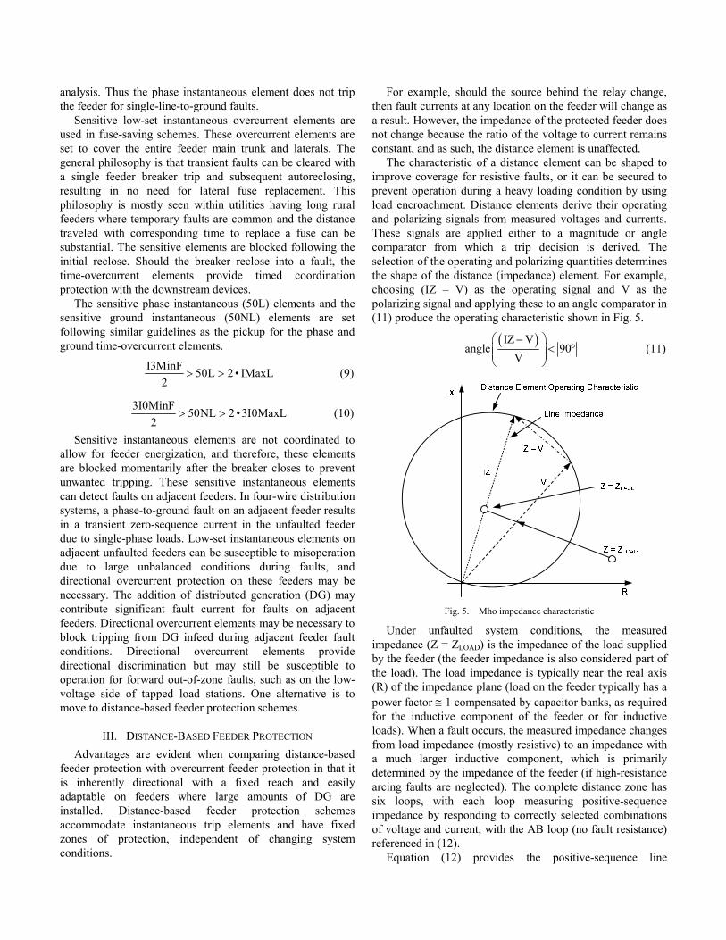
The characteristic of a distance element can be shaped to improve coverage for resistive faults, or it can be secured to prevent operation during a heavy loading condition by using load encroachment. Distance elements derive their operating and polarizing signals from measured voltages and currents. These signals are applied either to a magnitude or angle comparator from which a trip decision is derived. The selection of the operating and polarizing quantities determines the shape of the distance (impedance) element. For example, choosing (IZ – V) as the operating signal and V as the polarizing signal and applying these to an angle comparator in (11) produce the operating characteristic shown in Fig. 5.
( )IZ V
angle 90V
⎛ ⎞−< °⎜ ⎟⎜ ⎟
⎝ ⎠ (11)
Fig. 5. Mho impedance characteristic
Under unfaulted system conditions, the measured impedance (Z = ZLOAD) is the impedance of the load supplied by the feeder (the feeder impedance is also considered part of the load). The load impedance is typically near the real axis (R) of the impedance plane (load on the feeder typically has a power factor ≅ 1 compensated by capacitor banks, as required for the inductive component of the feeder or for inductive loads). When a fault occurs, the measured impedance changes from load impedance (mostly resistive) to an impedance with a much larger inductive component, which is primarily determined by the impedance of the feeder (if high-resistance arcing faults are neglected). The complete distance zone has six loops, with each loop measuring positive-sequence impedance by responding to correctly selected combinations of voltage and current, with the AB loop (no fault resistance) referenced in (12).
Equation (12) provides the positive-sequence line

impedance of the faulted line section. V = VA – VB, I = IA – IB, Z = V/I = m Z1L (12)
where: Z1L is the positive-sequence line impedance. m is the distance to the fault in per unit of Z1L [2].
The distance-based feeder protection discussed in this paper is a combination of traditional overcurrent protection coordination and distance elements. Both mho and quadrilateral elements are applied in this implementation of distance-based feeder protection. For details on both mho and quadrilateral distance elements and for direction to further references, see [1], [2], [3], [4], [5], and [6].
IV. CURRENT INFEED DUE TO DISTRIBUTED GENERATION The addition of generation has a significant impact on
feeder protection. Considering the case of a line-end three-phase fault for the circuit shown in Fig. 6, we can calculate the fault current at the feeder end with no generation as follows:
SYSNDG
SYS S H
VIF
Z Z Z=
+ + (13)
where: ZSYS is the impedance of the utility source. ZS is the impedance from the substation to the generator. ZH is the impedance from the generator to the line end. VSYS is the voltage behind the source impedance.
When we add the generator and neglect load, the total fault current is the following:
( )
SYSDG
DG SYS SH
DG SYS S
VIF
Z • Z ZZ
Z Z Z
=+
++ +
(14)
where: ZDG is the combined impedance of the generator and step-up transformer. ZSYS is the impedance of the utility source.
Fig. 6. A distribution feeder with connected generation
The fault current contribution from the utility source is now the following:
DGS DG
DG SYS S
ZI IF •
Z Z Z=
+ + (15)
The fault current contribution from the DG is the following:
( )SYS S
H DGDG SYS S
Z ZI IF •
Z Z Z+
=+ +
(16)
If we calculate the fault current contribution from the utility source of Fig. 1 for arbitrary values of ZS, ZH, and ZDG, we find that the addition of local generation always reduces the fault current contribution from the substation. Depending on the size and location of the generator, the overcurrent protection located at the substation may need to be set very sensitive due to the ZDG impact of the generator relative to ZSYS + ZS and still be able to detect faults at the end of the line, including both solid and resistive faults.
Ground overcurrent protection can be set to be more sensitive than phase overcurrent protection because it does not measure balanced load. However, the available ground fault current at the substation is further affected by the method of grounding at the generator transformer. The optimal grounding method is always a tradeoff between fault current contribution and acceptable overvoltages. The type of grounding at the generator facility must be compatible with the system to which it will be connected. For this reason, the grounding on the generator step-up transformer at the utility interconnection is usually mandated by the utility. Effective grounding is often chosen for four-wire networks in order to limit temporary overvoltages to a safe value to protect single-phase loads and surge arrestors. The zero-sequence impedance of an effectively grounded system is less than or equal to three times the positive-sequence impedance (X0 ≤ 3 • X1 and R0/X1 ≤ 1). A solidly grounded connection at the generator transformer is often avoided because although it successfully limits ground fault temporary overvoltages, it also produces excessive ground fault current and therefore reduces the utility-supplied ground fault current, effectively desensitizing the feeder protection. Unbalanced load conditions present on four-wire feeders limit the sensitivity of ground fault protection, and thus neutral grounding reactors on the primary side of the generator step-up transformer are sized to maintain an effectively grounded system yet still provide the utility with the ground fault current required for coordination. The secondary or tertiary winding of the generator step-up transformer must also allow the flow of zero-sequence currents. In three-wire networks, loads are connected phase to phase. The load transformer primary windings are typically wye ungrounded or delta. Sensitive ground fault protection can be applied under these circumstances if generator step-up transformers tapped to three-wire networks also adopt the same primary connection as load transformers.

Distance protection is also impacted by local generation. The apparent feeder impedance is the impedance measured by the distance relay. On a feeder with a single source of fault current, the apparent impedance will agree closely with the actual impedance between the relay location and the fault point. With the addition of generation, this situation changes. The relay at the utility source substation sees only IS and VS. VS is the voltage drop for this feeder-end fault and is shown in (17).
( )S S S S H HV I • Z I I • Z= + + (17)
This results in an apparent impedance of the following:
S HHS_ APP S H H S H
S S
I IIZ Z Z • Z Z • Z
I I+
= + + = + (18)
This ZS_APP compares to the actual impedance of the fault: S_ ACT S HZ Z Z= + (19)
It can be seen that ZS_APP increases by (IH/IS) • ZH. When DG is added to the distribution feeder, the fault current from the generation adds to the fault current from the utility such that, for a feeder-end fault, the impedance measured is larger than the actual impedance. The greater the MVA rating of the generator, the greater the magnitude of IH and the greater the increase in impedance. This successfully decreases the effective reach of the distance element.
This apparent effect is also seen in ground distance relaying; however, the results shown in (18) are influenced by the fact that the fault current is modified with the addition of residual current multiplied by the K0 factor [3].
V. DISTANCE ELEMENT SETTING CRITERIA FOR DG APPLICATIONS
In this distance-based feeder protection application, the high-set instantaneous overcurrent elements 50H or 50NH are replaced with instantaneous quadrilateral distance elements. The sensitive low-set instantaneous elements 50L or 50NL are replaced with an instantaneous mho element, while the 51 time-overcurrent elements are maintained and torque-controlled by mho elements. Primary goals of the distance-based feeder protection scheme are to perform the following:
• Quickly clear temporary faults up to the end of the zone, maintaining the fuse-saving philosophy.
• Provide stepped remote backup protection for feeder sections beyond downstream reclosers.
• Provide secure directional supervision to discriminate between forward and reverse faults.
• Provide fast clearing of faults up to the first critical primary fuse in order to limit transformer through-fault damage.
• Provide improved coverage for high-resistive close-in faults.
• Provide shaping capabilities to limit the reach on tapped load stations.
• Provide improved settings flexibility to deal with the desensitizing effect of tapped DG on the feeder.
• Provide feeder coverage that is relatively immune to variations in source impedance.
• Provide unbalanced load encroachment to cater to lateral fuse failures on long lines with DG.
• Facilitate the evolution from radial to nonradial feeders.
Similar to the overcurrent scheme following the initial reclose, the sensitive low-set instantaneous mho equivalent protection elements are blocked and the 51 protection elements coordinate as in the overcurrent-based feeder protection, with distance elements providing torque control. This makes the overcurrent element directional, as is generally required on feeders with large amounts of DG.
Protection for phase faults is shown in Fig. 7.
21P1
21P2
21P3
R
X
Fig. 7. Phase distance elements
The 21P1 element is set to underreach the first lateral fuse and is never blocked. In cases (where this fuse is too close to the station) that would limit the reach of the 21P1 element and minimize the effectiveness of this high-set instantaneous protection, the overreaching of the fuse is accepted, provided that the total operating time of the feeder protection plus breaker operating time is greater than the total clearing time of the fuse with margin.
In applications where there is no midline recloser, 21P2 is the low-set instantaneous fuse-saving element and is set at 125 to 150 percent of the maximum apparent feeder impedance (i.e., the impedance seen by the relay when the generator is connected with a minimum system behind the relay and the DG source is maximized). The reach settings should be checked to avoid tripping for a fault on the low-voltage side of a tapped transformer. Normally, the transformer will provide sufficient impedance to prevent this, but tripping can occur in the case of a long line and/or a large tapped load. Fig. 8 illustrates the potential for operation of the 21P2 element for a ground fault downstream of a distribution transformer.

Fig. 8. Risk of Zone 2 operation for low-voltage faults
In applications where a midline recloser is present, 21P2 is set for high-speed clearing and underreaches the midline recloser. In this case, overreaching is not acceptable, so 21P2 is set at 75 to 80 percent of the positive-sequence line impedance. The 21P3 torque controls the 51P element and is set at 150 to 200 percent of the maximum apparent feeder impedance, protecting the entire feeder beyond all midline reclosers and lateral fuses to the end of the feeder. In applications where a midline recloser exists, the 21P3 element is set to see the entire feeder and includes a low-set instantaneous 100-millisecond-delayed trip, providing the sequence coordination required for a fast curve trip from the recloser to be detected by the feeder protection and block this 100-millisecond-delayed trip path. The 100-millisecond trip path also provides the fuse-saving protection for the portion of the feeder between the 21P2 element and the midline recloser. The recloser total clearing time (protection time plus the interrupter open interval time) should be checked to ensure there is adequate margin. In addition, the 21P3 element provides definite-time backup protection for telecommunications cables located on the same right of way that may otherwise be damaged because of induced ground current in the sheath.
The maximum apparent impedance is used when setting both the 21P2 (when there is no midline recloser) and 21P3 elements.
The distance elements applied for a ground fault are illustrated in Fig. 9.
Fig. 9. Ground distance elements
The Zone 1 ground 21G1 element replaces the ground high-set instantaneous 50NH element and is set to underreach the first lateral fuse. In applications where there is no midline recloser, 21G2 is used as the instantaneous fuse-saving element, as is the case for the phase protection element. 21G3 is a supervision element set to supervise 51N. This element is intended to overreach and is set at 150 to 200 percent of the apparent feeder impedance.
The 51N element is set to coordinate with both upstream and downstream devices, as is detailed in the overcurrent feeder protection scheme. The 51N overcurrent element forward and reverse fault discrimination is achieved by using the directionality provided by the 21G3 element. Hydro One Networks Inc. requires that when the DG source is tripped because of a feeder fault, then the ground source associated with the distributed generator also needs to be isolated so that time coordination after reclosing is based on all downstream generators being removed, similar to a conventional radial feeder.
The impedance characteristics should be checked to ensure sufficient coverage for high-resistance faults. This is important for short lines where the reduced reach settings may limit the fault resistance coverage.
To improve the security of the phase distance or phase overcurrent elements on heavily loaded feeders, load encroachment is used.
The load-encroachment element operates as follows. The element measures the apparent positive-sequence impedance being supplied by the feeder. If the measured positive-sequence impedance falls within the load-encroachment region shown in Fig. 10, the load-encroachment output is asserted. The output from the load-encroachment logic blocks the phase distance and phase overcurrent elements from operating.
R
jX
Load-Encroachment Operate
Load-Encroachment Operate
Fig. 10. Load-encroachment characteristic
This phase load-encroachment element is based on the assumption that load is a balanced condition, which is acceptable for the transmission system. However, on the

four-wire distribution system, load can sometimes become quite unbalanced. Utilities must manage unbalanced load that is due to the loss of a single-phase lateral or simply unbalanced load from sections of the feeder that may not be under utility control. In an effort to provide a load-encroachment element that allows for unbalanced loads and accommodates the compensated distance elements in this distance-based feeder protection, a fourth distance element is used. The 21G4 element is set at the same reach as the 21G3 element and includes blinders, as shown in the neutral load encroachment of Fig. 11.
Fig. 11. Coverage provided by Zone 3 and Zone 4
The 50G element is set at 150 percent of the maximum expected load unbalance. This worst-case maximum load unbalance would typically be created when a heavily loaded single-phase lateral fuse is blown.
The ground or compensated load encroachment is provided with the following logic:
• Low set = (21G4 OR 50G) AND 21G2 • Timed (overcurrent) = (21G4 OR 50G) AND 21G3
or 51N torque-controlled by 21G3 This distance-based feeder protection has two additional
backup settings. The first backup setting is a definite-time trip, where both 21G3 and 21P3 are set to trip after they have been asserted for 2.8 seconds, providing telecommunications cable sheath protection. A second backup trip is set as a current-only condition. This trip is set with a definite-time delay on the low-set phase elements with fuse failure supervision to cater for voltage transformer (VT) fuse failure conditions. The 50L and 50NL elements used in this backup protection are set as described in the overcurrent feeder protection, but with a definite-time delay. Both these backup settings are set to clear low-magnitude or lateral faults that fail to be tripped in less than 3 seconds by the torque-controlled 51 and 51N elements.
VI. EXAMPLE FEEDER MODEL WITH DISTRIBUTED GENERATION
The following system is used to review the application of distance protection on feeders. Table I and Fig. 12 provide the data for the example system.
The example system has a per-unit base of 27.6 kV and 100 MVA.
The zero-sequence impedance of the G1 and G2 transformers excludes the neutral reactor impedance. A 10 Ω neutral reactor is used in the neutral of TX G1 and TX G2 for this example system.
All impedance values are calculated in Ω primary. Typically, relay reach settings are entered in Ω secondary, requiring a conversion using the current transformer (CT) and VT ratios.
TABLE I SYSTEM PARAMETERS
Real pu Imag pu Mag pu Ang
Z1 SYS 0.0265 0.3681 0.3691 85.9
Z0 SYS 0.0004 0.3099 0.3099 89.9
Z1 Fuse 0.1340 0.5310 0.5476 75.8
Z0 Fuse 0.3640 1.4380 1.4834 75.8
Z1S 0.2680 1.0620 1.0953 75.8
Z0S 0.7280 2.8760 2.9667 75.8
Z1H 0.9255 1.7105 1.9448 61.6
Z0H 2.2159 4.9648 5.4369 65.9
Z1 Feeder 1.1935 2.7725 3.0185 66.7
Z0 Feeder 2.9439 7.8408 8.3753 69.4
Z1 TX (G1, G2) 0 0.5750 0.5750 90
Z0 TX (G1, G2) 0 0.5000 0.5000 90
Xd” (G1, G2) 0 1.6060 1.6060 90
Fig. 12. Example system

We assume that the impedance relay allows the ground fault compensation factor K0 to be entered directly, allowing ground distance reach settings to be specified in terms of positive-sequence impedance. K0 = (Z0/Z1 – 1)/3 = 0.5921 at 4.2° (20)
where: Z0 is the zero-sequence impedance of the Z0 feeder. Z1 is the positive-sequence impedance of the Z1 feeder from Table I.
In this example, 21P1 and 21G1 are never blocked and are set to underreach the first critical fuse. These elements provide fast clearing for close-in feeder faults and limit the impact of through-fault current on station transformers.
The positive-sequence impedance to the first critical fuse is 4.17 at 76° Ω as calculated using the data from Table I. For security purposes, the 21P1 zone is set to reach 80 percent of this value. Recall that this element has a quadrilateral characteristic. The characteristic will intersect the reactive axis at 0.8 • 4.17 sin(76) = 3.23 Ω. The left blinder is set to intersect the resistive axis at the same value of 3.23 Ω, and the right blinder is set to no greater than five times the reactive reach, or 5 • 3.23 = 16.15 Ω. In this case, the right blinder is set to 12.0 Ω. We verify the maximum load at the right blinder reach, (27.6 kV)2/(12 + j3.23) Ω = 61 MVA. We reduce the resistive reach, as required, so that the maximum load or inrush current will not encroach on 21P1.
The 21G1 element is set to underreach the first critical fuse by 25 percent. This element also has a quadrilateral characteristic and is set to intersect the reactive axis at 0.75 • 4.17 sin(76) = 3.03 Ω. The left blinder is also set to intersect the resistive axis at 3.03 Ω, and the right blinder is set at five times the reactive reach, or 5 • 3.03 = 15.15 Ω. In this case, the right blinder is set to 12.0 Ω.
This example includes a midline recloser, and therefore, 21P2 and 21G2 are set to underreach the recloser. The Zone 2 elements, in this case, are instantaneous and are blocked for a limited time after the first trip to allow for timed trip coordination following the reclose. If the midline recloser is not available, then 21P2 and 21G2 are set to 150 percent of the maximum apparent impedance (with all generation connected) for a feeder-end fault.
The 21P2 element is set to reach up to 80 percent of the positive-sequence line impedance to the recloser. The positive-sequence line impedance is 8.33 Ω. The 21P2 reach is 0.80 • 8.33 = 6.66 Ω. The equivalent setting for a relay with a line characteristic of 60° is calculated as 6.66 Ω/cos(76 – 60) = 6.93 Ω. This setting of 6.93 Ω provides a reach of 6.66 at 76° Ω, which is 80 percent of the positive-sequence impedance at 76°. We now check the maximum load in MVA at the maximum expected load angle of 30°, (27.6 kV)2/(6.93 Ω • cos(60 – 30)) = 127 MVA. We supervise this element using the relay load-encroachment characteristic if the maximum load encroaches on the 21P2 characteristic.
The 21G2 element is set to reach up to 75 percent of the
positive-sequence line impedance to the recloser. The positive-sequence line impedance is 8.33 at 76° Ω. The 21G2 reach is therefore 0.75 • 8.33 at 76° = 6.25 at 76° Ω. The equivalent setting for a relay with a line characteristic of 60° is calculated as 6.25 Ω/cos(76 – 60) = 6.50 at 60° Ω. This setting of 6.50 at 60° Ω provides a reach of 6.25 at 76° Ω, which is 75 percent of the positive-sequence impedance at 76°.
For this example, where 21P2 and 21G2 underreach the midline recloser, 21P3 and 21G3 are set to torque-control the inverse-time overcurrent elements. The Zone 3 impedance elements together with the inverse-time overcurrent elements provide time coordination following the reclose that allows for reclosers or fused laterals to trip, as required. Because the Zone 2 impedance elements are set to underreach the recloser, the Zone 3 elements are allowed to trip for an initial fault after a 100-millisecond delay. This definite-time trip is blocked following the first trip. This delay allows for the recloser to operate for downstream faults while still maintaining fast clearing for faults between the substation and the recloser.
A check of the apparent impedance due to the DG infeed is carried out as follows. A line-end three-phase fault is calculated in (21).
( ) ( )SYS
SYS S DGH
SYS S DG
VI3F 320 762j A
Z1 Z1 • Z1Z1
Z1 Z1 Z1
= = −+
++ +
(21)
where: Z1SYS is the base system impedance. Z1H is the line impedance minus the impedance from S to the midline recloser. Z1S is the impedance from S to the midline recloser. Z1DG is the total impedance of DG1 plus the impedance of the DG1 transformer in parallel with the impedance of DG2 plus the impedance of the DG2 transformer.
All are positive-sequence values from Table I. The contribution from the substation is the following:
( )DGSYS
SYS S DG
I3F • Z1I3F 174 309j A
Z1 Z1 Z1= = −
+ + (22)
The DG contribution is as follows:
( ) ( )SYS S
DGSYS S DG
I3F • Z1 Z1I3F 145 452j A
Z1 Z1 Z1+
= = −+ +
(23)
The increase in apparent impedance is the following:
( )DG HH _ NEW
SYS
I3F • Z1Z1 12.8 15.2 j
I3F= = + Ω (24)
The following is the apparent impedance with DG connected, expressed in per unit of the actual line impedance:
LINE H _ NEW
LINE
Z1 Z11.84 at –8 pu
Z1+
= ° (25)

Consequently, 21P3 is set to 200 percent of the maximum apparent impedance. The impedance will typically overreach considerably under maximum apparent impedance conditions due to a large source impedance and a lower tapped generation impedance. The three-phase feeder-end fault, with minimum fault current from the utility and maximum fault current from the DG, results in 42.3 Ω at 59°. The 21P3 reach is 2 • 42.3 Ω at 59° = 84.6 Ω at 59°. This setting is adjusted for a relay characteristic angle of 60°, and the setting becomes 84.6 Ω/cos(59 – 60) = 84.7 Ω at 60°. We now check the maximum load in MVA at the maximum expected load angle of 30°, (27.6 kV)2/(84.7 Ω • cos(60 – 30)) = 10.38 MVA. We include the load-encroachment characteristic if the maximum load encroaches on the 21P3 characteristic.
The 21G3 element is set to 200 percent of the maximum apparent impedance. A single-phase-to-ground feeder-end fault, with minimum fault current from the utility and maximum fault current from the DG, results in 43.6 Ω at 59°. The 21G3 reach is 2 • 43.6 Ω at 59° = 87.2 Ω at 59°. This setting is adjusted for a relay characteristic angle of 60°, and the setting becomes 87.2 Ω/cos(61 – 60) = 87.2 Ω at 60°.
VII. IMPACT OF DISTANCE RELAYING ON FEEDER PROTECTION COST
The addition of generation usually requires that feeder protection be upgraded to permit directional supervision of overcurrent functions. Today, the difference in product cost between a distance relay and a directional overcurrent relay is minimal relative to the installation cost. The protection engineer needs only to specify what protection elements are required, and the various solutions are very close in material, engineering, and installation costs. The feeder breaker is normally located in a station where VTs are already available and connected to the bus. These VTs can be used for directional overcurrent protection and distance protection, as well as load information for each feeder from the intelligent electronic device (IED). The IED voltage inputs are designed to have high input impedances, so connecting multiple feeder protective relays to a single set of bus VTs is usually not a problem. Where space is an issue, the VT can be installed on the feeder, but this is not the most cost-effective solution because the life-cycle cost of having VTs on every feeder is greater than having a single set of three VTs on the bus. Existing three-wire systems may be limited to two phase-to-phase VTs on the bus. Full functionality of the distance relaying presented in this paper requires three phase-to-neutral connected VTs.
VIII. LEARNING CURVE FOR DISTANCE PROTECTION APPLICATIONS
Distance relaying has an arguable advantage compared with overcurrent relaying in that the protection engineer can define zones of protection in the form of reach settings based on circuit impedances. However, there are sometimes subtle
aspects related to wiring and setting a distance relay that may not be immediately obvious to someone who is unfamiliar in the field. For instance, a grounded-wye VT connection is required, in most cases, for the correct operation of a ground distance element—a fact that may escape an inexperienced protection engineer. Often, a protection engineer may be responsible for either distribution or transmission, but not both, and, in such cases, will be well-versed in one field, but not the other. In some cases, a distribution company may need to agree to a one-time investment in training the protection and control staff in distance protection. Given the benefits of distance protection, this investment is well justified. There are many options for the required training.
Relay manufacturers usually offer transmission relay training for their products, including procedures for setting and testing. Methods for analysis of distance relay operations, an important but sometimes overlooked task, may also be included. This training can take the form of conventional classroom instruction, website-based training, or instructional DVDs. Such training will typically be product-specific and may assume a basic level of knowledge. In addition, several relay schools provide more comprehensive and generic training for both distribution protection and transmission protection. These schools may prove better sources of instruction but will likely entail travel to a training center.
In the past, colleges and universities have not been the best sources for instruction on protective relaying. Now, an increasing number of institutions are providing detailed levels of both theoretical and practical instruction. When locally accessible, this avenue, while requiring a longer and higher level of commitment from the student, can provide the best outcome.
IX. CASE STUDIES The distance scheme described in Section V has been used
in several applications. The following cases show faults on protected feeders and the resulting relay behavior.
A. Case 1 Fig. 13 and Fig. 14 show a BG fault on a feeder with DG
and a midline recloser. The Zone 2 reach has been reduced to prevent a pickup for faults downstream from the recloser. The initial fault is cleared by Zone 2 after a delay of 50 milliseconds. The line subsequently recloses. The re-energization current includes a significant inrush component. After 230 milliseconds, a second fault occurs. For the second fault, Zone 2 is blocked, and the relay begins to time out on the 51N element supervised by Zone 3 (pickup flag is not shown). Fig. 13 shows the B-phase voltage and current and the relay internal flags.

Fig. 13. Time plot for Case 1
Fig. 14 is an impedance plot showing the first fault, the re-energization, and the second fault.
Fig. 14. Impedance plot for Case 1
B. Case 2 This case shows a relay operation for a feeder with DG.
This feeder also has a midline recloser. In this case, the feeder is importing power prior to an ABC fault occurrence. The fault is inside the Zone 2 characteristic (Fig. 15). The relay takes one-half of a cycle to detect the fault. The feeder successfully recloses (Fig. 16).
The load current is significantly higher following reclose, owing to the loss of local generation.
X (
Sec
onda
ry
Fig. 15. Impedance plot for Case 2
Fig. 16. Time plot for Case 2

X. CONCLUSION The addition of DG can result in a loss of protection
sensitivity, a loss of protection coordination, and tripping for out-of-zone faults. Distance relays are useful in addressing these challenges. Distance relays are inherently directional, have operating characteristics that can be shaped, and are influenced less than overcurrent relaying by changing system conditions.
This paper outlines a methodology for the application of distance relaying to feeders that include generation. The approach preserves the sensitivity and effectiveness of fuse-saving schemes.
The methodology has been successfully applied, as evidenced by the presented relay event files.
XI. REFERENCES
[1] J. L. Blackburn and T. J. Domin, Protective Relaying: Principles and Applications, 3rd ed. Taylor & Francis Group, LLC, Boca Raton, FL, 2007.
[2] H. J. Altuve Ferrer and E. O. Schweitzer, III (eds.), Modern Solutions for Protection, Control, and Monitoring of Electric Power Systems. Schweitzer Engineering Laboratories, Inc., Pullman, WA, 2010.
[3] W. A. Elmore, Protective Relaying Theory and Applications, 2nd ed. Marcel Dekker, Inc., New York, NY, 2004.
[4] E. O. Schweitzer, III and J. Roberts, “Distance Relay Element Design,” proceedings of the 46th Annual Conference for Protective Relay Engineers, College Station, TX, April 1993.
[5] F. Calero, “Distance Elements: Linking Theory With Testing,” proceedings of the 35th Annual Western Protective Relay Conference, Spokane, WA, October 2008.
[6] F. Calero, A. Guzmán, and G. Benmouyal, “Adaptive Phase and Ground Quadrilateral Distance Elements,” proceedings of the 36th Annual Western Protective Relay Conference, Spokane, WA, October 2009.
XII. BIOGRAPHIES
Amy Sinclair received her BSc in electrical engineering from Queen’s University, Kingston, in 1989. She joined Ontario Hydro in 1989, working for ten years as a protection and control engineer in the areas of design, operations, and project management. In 2000, she joined ELECSAR Engineering as a project manager with a focus on protective relaying and substation design. Since December 2006, she has been employed with Schweitzer Engineering Laboratories, Inc. as a field application engineer, located in Chatham, Ontario. She has been registered as a professional engineer of Ontario since 2001.
Dale Finney received his bachelor’s degree from Lakehead University and his master’s degree from the University of Toronto, both in electrical engineering. He began his career with Ontario Hydro, where he worked as a protection and control engineer. Currently, Dale is employed as a senior power engineer with Schweitzer Engineering Laboratories, Inc. His areas of interest include generator protection, line protection, and substation automation. He is a holder of several patents and has authored more than a dozen papers in the area of power system protection. He is a member of the main committee of the IEEE PSRC, a member of the rotating machinery subcommittee, and a registered professional engineer in the province of Ontario.
David Martin received his BASc at the University of Waterloo, Canada, in 1979. He has over 30 years of experience with power systems. In 1981, David became a member of the professional engineers of Ontario, Canada, and joined Ontario Hydro as a field protection and control engineer. In 1988, he joined the Ontario Hydro protection design department as a relay engineer with a focus on protection applications. In 2001, David became a senior protection and control specialist with Hydro One Networks Inc. and is currently a member of the advanced distribution solutions team.
Pankaj Sharma, P.E., received his bachelor of electrical engineering in 1985 from Saurashtra University, Gujarat, India. He began his 25-year professional career in power systems when he joined Gujarat State Electricity Board in India (an organization similar to Ontario Hydro), where he worked for 17 years. As a divisional manager in the transmission department, Pankaj commissioned and operated a number of extra-high-voltage class transformer switching stations and transmission lines. In 2002, he joined Canadian Electrical Services as a design engineer with a focus on optimizing transformer windings and minimizing core-copper losses. For a short period, Pankaj worked at Toronto Hydro as a project manager. In 2006, he joined Hydro One Networks Inc., where he is currently a sustainment manager in the protection and control department and is responsible for the adequacy of the protection and control at substations. Pankaj is also accountable for technical interconnection requirements for distribution generation. He has vast experience in utility and industrial segments and has thorough knowledge of high-voltage transformer stations and power distribution systems. Pankaj has been registered as a professional engineer of Ontario since 2005.
Previously presented at the 2012 Texas A&M Conference for Protective Relay Engineers and the 2013 IEEE Rural Electric Power Conference.
© 2012, 2013 IEEE – All rights reserved.20130110 • TP6516