Diss Agrément Certificate 12/4895 · Agrément Certificate 12/4895 Product Sheet 1 The BBA has...
16
Page 1 of 16 TECHNICAL APPROVALS FOR CONSTRUCTION APPROVAL INSPECTION TESTING CERTIFICATION Glazing Vision Ltd Saw Mills Road Diss Norfolk IP22 4RG Tel: 0333 8000 881 Fax: 0333 8000 882 e-mail: [email protected] website: www.glazing-vision.co.uk British Board of Agrément tel: 01923 665300 Bucknalls Lane fax: 01923 665301 Watford e-mail: [email protected] Herts WD25 9BA website: www.bbacerts.co.uk ©2013 The BBA is a UKAS accredited certification body — Number 113. The schedule of the current scope of accreditation for product certification is available in pdf format via the UKAS link on the BBA website at www.bbacerts.co.uk Readers are advised to check the validity and latest issue number of this Agrément Certificate by either referring to the BBA website or contacting the BBA direct. GLAZING VISION ROOFLIGHTS FLUSHGLAZE ROOFLIGHTS This Agrément Certificate Product Sheet (1) relates to Flushglaze Rooflights, for use on flat and sloping roof and wall (up to three sides) installations of new and existing domestic buildings, to provide natural light. (1) Hereinafter referred to as ‘Certificate’. CERTIFICATION INCLUDES: • factors relating to compliance with Building Regulations where applicable • factors relating to additional non-regulatory information where applicable • independently verified technical specification • assessment criteria and technical investigations • design considerations • installation guidance • regular surveillance of production • formal three-yearly review. KEY FACTORS ASSESSED Light and solar transmittance — the products provide a means of natural lighting to the interior of a building (see section 6). Thermal properties — U values can meet the Building Regulations requirements depending on frame/glass/size combination (see section 7). Condensation risk — the risk of condensation on the product’s internal surface will depend on the product selected and the building type (see section 8). Strength and stability — the products will adequately resist imposed loads (see section 9). Water resistance — the products are weathertight (see section 10). Behaviour in relation to fire — the glazing used in the rooflights can be considered as non-combustible material and the products are therefore unrestricted under the Building Regulations (see section 11). Durability — with appropriate maintenance, the life of the rooflights should be at least 20 years in non-corrosive environments. Any slight external colour change or surface dulling of the frame that might occur will be uniform over the visible surfaces of the frame (see section 16). Agrément Certificate 12/4895 Product Sheet 1 The BBA has awarded this Certificate to the company named above for the products described herein. These products have been assessed by the BBA as being fit for their intended use provided they are installed, used and maintained as set out in this Certificate. On behalf of the British Board of Agrément Date of Second issue: 7 November 2013 John Albon — Head of Approvals Claire Curtis-Thomas Originally certificated on 27 February 2013 Energy and Ventilation Chief Executive
Transcript of Diss Agrément Certificate 12/4895 · Agrément Certificate 12/4895 Product Sheet 1 The BBA has...

Page 1 of 16
TECHNICAL APPROVALS FOR CONSTRUCTION
APPROVAL
INSPECTION
TESTING
CERTIFICATION
Glazing Vision LtdSaw Mills RoadDissNorfolk IP22 4RGTel: 0333 8000 881 Fax: 0333 8000 882e-mail: [email protected]: www.glazing-vision.co.uk
British Board of Agrément tel: 01923 665300Bucknalls Lane fax: 01923 665301Watford e-mail: [email protected] WD25 9BA website: www.bbacerts.co.uk©2013
The BBA is a UKAS accredited certification body — Number 113. The schedule of the current scope of accreditation for product certification is available in pdf format via the UKAS link on the BBA website at www.bbacerts.co.uk
Readers are advised to check the validity and latest issue number of this Agrément Certificate by either referring to the BBA website or contacting the BBA direct.
GLAZING VISION ROOFLIGHTS
FLUSHGLAZE ROOFLIGHTS
This Agrément Certificate Product Sheet(1) relates to Flushglaze Rooflights, for use on flat and sloping roof and wall (up to three sides) installations of new and existing domestic buildings, to provide natural light.(1) Hereinafter referred to as ‘Certificate’.
CERTIFICATION INCLUDES:• factors relating to compliance with Building Regulations
where applicable• factors relating to additional non-regulatory information
where applicable• independently verified technical specification• assessment criteria and technical investigations• design considerations• installation guidance• regular surveillance of production• formal three-yearly review.
KEY FACTORS ASSESSEDLight and solar transmittance — the products provide a means of natural lighting to the interior of a building (see section 6).Thermal properties — U values can meet the Building Regulations requirements depending on frame/glass/size combination (see section 7).Condensation risk — the risk of condensation on the product’s internal surface will depend on the product selected and the building type (see section 8).Strength and stability — the products will adequately resist imposed loads (see section 9).Water resistance — the products are weathertight (see section 10).Behaviour in relation to fire — the glazing used in the rooflights can be considered as non-combustible material and the products are therefore unrestricted under the Building Regulations (see section 11).Durability — with appropriate maintenance, the life of the rooflights should be at least 20 years in non-corrosive environments. Any slight external colour change or surface dulling of the frame that might occur will be uniform over the visible surfaces of the frame (see section 16).
Agrément Certificate12/4895
Product Sheet 1
The BBA has awarded this Certificate to the company named above for the products described herein. These products have been assessed by the BBA as being fit for their intended use provided they are installed, used and maintained as set out in this Certificate.
On behalf of the British Board of Agrément
Date of Second issue: 7 November 2013 John Albon — Head of Approvals Claire Curtis-Thomas
Originally certificated on 27 February 2013 Energy and Ventilation Chief Executive

Page 2 of 16
In the opinion of the BBA, Flushglaze Rooflights, if installed, used and maintained in accordance with this Certificate, will meet or contribute to meeting the relevant requirements of the following Building Regulations (the presence of a UK map indicates that the subject is related to the Building Regulations in the region or regions of the UK depicted):
The Building Regulations 2010 (England and Wales) (as amended)
Requirement: A1 Loading
Comment: The products will have sufficient strength and stiffness to sustain the design loads. See sections 9.1, 9.3 and 9.4 of this Certificate.
Requirement: B2(1) Internal fire spread (linings)
Comment: The glazing used in the products can be regarded as non-combustible material and, therefore, can be taken as having a Class A1 classification. See section 11.1 of this Certificate.
Requirement: B4(2) External fire spread
Comment: When used in rooflights, unwired glass at least 4 mm thick can be regarded as having an AA designation. See sections 11.2 and 11.3 of this Certificate.
Requirement: C2(b) Resistance to moisture
Comment: The rooflights will not adversely affect the resistance of the roof to the passage of moisture. The products provide adequate resistance to the ingress of precipitation. See section 10.1 of this Certificate.
Requirement: C2(c) Resistance to moisture
Comment: The risk of surface condensation on the products will depend on the building humidity class and the product selected. See sections 8.1 to 8.3 of this Certificate.
Requirement: L1(a)(i) Conservation of fuel and power
Comment: See sections 6.2 and 7 of this Certificate.Regulation: 7 Materials and workmanship
Comment: The products are acceptable when used in accordance with this Certificate. See section 16.1 and the Installation part of this Certificate.
Regulation: 26 CO2 emission rates for new buildings
Comment: The products can contribute to satisfying this Regulation. See sections 6.2 and 7 of this Certificate.
The Building (Scotland) Regulations 2004 (as amended)
Regulation: 8(1)(2) Durability, workmanship and fitness of materials
Comment: The use of the products satisfies the requirements of this Regulation. See sections 15.2, 16.1 and the Installation part of this Certificate.
Regulation: 9 Building standards applicable to constructionStandard: 1.1(b) Structure
Comment: The products will have sufficient strength and stiffness to sustain design loads, with reference to clause 1.1.1(1)(2). See sections 9.1, 9.3 and 9.4 of this Certificate.
Standard: 2.5 Internal linings
Comment: The glazing, as part of the ceiling lining, is non-combustible, with reference to clause 2.5.1(1)(2). See section 11.1 of this Certificate.
Standard: 2.8 Spread from neighbouring buildings
Comment: When used in rooflights, glass at least 4 mm thick is classified as ‘low vulnerability’ material, with reference to clause 2.8.1(1)(2). See sections 11.2 and 11.3 of this Certificate.
Standard: 3.10 Precipitation
Comment: The products provide adequate resistance to the ingress of precipitation, with reference to clause 3.10.1(1)(2). See section 10.1 of this Certificate.
Standard: 3.15 Condensation
Comment: The risk of surface condensation on the products will depend on the building humidity class and the products selected, with reference to clauses 3.15.1(1) and 3.15.4(1). See sections 8.1 to 8.3 of this Certificate.
Standard: 3.16 Natural lighting
Comment: The products can contribute to meeting this Standard.Standard: 6.1(b) Carbon dioxide emissionsStandard: 6.2 Building insulation envelope
Comment: With reference to clauses 6.1.2(1), 6.1.4(2), 6.1.6(1), 6.2.1(1)(2), 6.2.4(2), 6.2.6(1), 6.2.7(1), 6.2.8(2), 6.2.9(1)(2), 6.2.11(1)(2) and 6.2.13(1)(2), see sections 6.2 and 7 of this Certificate.
Standard: 7.1(a)(b) Statement of sustainability
Comment: The products can contribute to satisfying the relevant requirements of Regulation 9, Standards 1 to 6, and, therefore will contribute to a construction meeting a bronze level of sustainability as defined in this Standard. In addition the products can contribute to a construction meeting a higher level of sustainability as defined in this Standard, with reference to clauses 7.1.4(1)(2) [Aspects 1(1)(2) and 2(1)], 7.1.6(1)(2) [Aspects 1(1)(2) and 2(1)] and 7.1.7(1)(2) [Aspect 1(1)(2)]. See section 7 of this Certificate.
Regulation: 12 Building standards applicable to conversions
Comments: All comments given for the products under Regulation 9, Standards 1 to 6, also apply to this Regulation, with reference to clause 0.12.1(1)(2) and Schedule 6(1)(2).
(1) Technical Handbook (Domestic). (2) Technical Handbook (Non-Domestic).
Regulations

Page 3 of 16
The Building Regulations (Northern Ireland) 2012
Regulation: 23 Fitness of materials and workmanship
Comment: The products are acceptable. See section 16.1 and the Installation part of this Certificate.Regulation: 28(b) Resistance to moisture and weather
Comment: The products will not adversely affect the resistance of the roof to the passage of moisture. See section 10.1 of this Certificate.
Regulation: 30 Stability
Comment: The products have sufficient strength and stiffness to sustain the design loads. See sections 9.1, 9.3 and 9.4 of this Certificate.
Regulation: 34 Internal fire spread — Linings
Comment: The glazing used in the products can be regarded as non-combustible material and, therefore, can be taken as having a Class A1 classification. See section 11.1 of this Certificate.
Regulation: 36(b) External fire spread
Comment: When used in rooflights, unwired glass at least 4 mm thick can be regarded as having an AA designation. See sections 11.2 and 11.3 of this Certificate.
Regulation: 39(a)(i) Conservation measuresRegulation: 40(2) Target carbon dioxide emission rate
Comment: See sections 6.2 and 7 of this Certificate.
Construction (Design and Management) Regulations 2007Construction (Design and Management) Regulations (Northern Ireland) 2007Information in this Certificate may assist the client, CDM co-ordinator, designer and contractors to address their obligations under these Regulations.See section: 3 Delivery and site handling (3.5) of this Certificate.
Additional Information
NHBC Standards 2013In the opinion of the BBA, the use of Flushglaze Rooflights, in relation to this Certificate is not subject to the requirements of these Standards.
Technical Specification
1 Description1.1 Flushglaze Rooflights comprise glass sealed glazed units fixed in a polyester powder coated aluminium frame, grey finish on the outside and white finish on the inside(1). They are available as double- or triple-glazed units for installation on flat or pitched roofs (minimum pitch 3°, minimum pitch for walk-on 1°), or for wall mounting (up to three sides). The sealed units are fixed to the frame using structural adhesive sealant. The T-shaped frame is fixed to a timber kerb(2), and angled sections to the wall. For typical installations, see Figures 1, 2, 3, 4 and 5.(1) Other colours are available; these are outside the scope of this Certificate.(2) The kerb and all ancillary items associated with its installation are outside the scope of this Certificate.
Figure 1 Wall mounted Flushglaze

Page 4 of 16
Figure 2 Walk-on Flushglaze
Figure 3 Multipart Flushglaze

Page 5 of 16
Figure 4 Typical Flushglaze installations
double-glazed Flushglaze kerb detail
expanding foam tape
double-sided structural glazing tapesiliconesealant
polyethylene bondbreaker/backing rod
butyl tape
structuraladhesivesealant
double-glazed Flushglaze wall abutment detail
siliconesealant
double-sided structural glazing tape
structural adhesive sealant
polyethylene bondbreaker/backing rod
expanding foam tape
expanding foam tape
polyethylene bondbreaker/backing rod
polyethylene bondbreaker/backing rod
polyethylene bondbreaker/backing rod
siliconesealant
siliconesealant
siliconesealant
structuraladhesivesealant
double-sided structural glazing tape
double-sided structural glazing tape
double-sided structural glazing tape
walk-on Flushglaze glazed kerb detail
structural adhesive seal
structural adhesive structural adhesive
walk-on Flushglaze glazed wall detail
structural adhesivesealant
polyethylene bondbreaker/backing rod
siliconesealant
double-sided structural glazing tape
triple-glazed Flushglaze kerb detail triple-glazed Flushglaze wall detail
butyl tape

Page 6 of 16
Figure 5 Typical fire-rated Flushglaze installation
fire-rated Flushglaze kerb detail
fire-rated double-glazed unit fire-rated silicone sealant
ceramic tape
glass adhesive
fire-rated silicone
ceramic tape
1.2 The products are available as:• double-glazed units — square, rectangular or circular shapes — single or multipart units — standard, walk-on or fire-rated
• triple-glazed units — square, rectangular or circular shapes — single or multipart units — standard.
1.3 Standard multipart units are joined together in three ways (see Figure 6), the seal between units comprising:• silicone seal joint — low modulus, neutral cure silicone weatherseal (black) and polyethylene bond breaker/backing
rod, both applied on-site. The maximum length of a silicone seal joint is 1300 mm (double- and triple-glazed units with toughened inner and outer pane) and 900 mm (double-glazed units with annealed laminated inner pane).
• back-to-back aluminium L-section — the polyester powder coated aluminium sections vary, depending on the rooflights’ specification, and rest on the timber kerb. Sections are held together with M6 countersunk stainless steel sexbolts, at approximately 600 mm centres. An obscured band is applied to the inner surface of the glazed unit. The seal between units comprises a silicone seal joint with low modulus, neutral cure silicone weatherseal (black) and polyethylene bond breaker/backing rod, both applied on-site. The maximum length of a back-to-back aluminium L-section is 4000 mm.
• glass fins — the depth depends on the overall rooflight dimensions and glass specification. Packing (8 mm thick) is positioned at 600 mm centres and a silicone bead is applied either side of the packer. The glass fins are supported by stainless steel brackets, which are fixed to kerb/timber trimmers (outside the scope of this assessment). The seal between units comprises a silicone seal joint with low modulus, neutral cure silicone weatherseal (black) and polyethylene bond breaker/backing rod, both applied on-site. The maximum length of a glass fin is 4000 mm.
Standard double-glazed units1.4 Standard 28 mm double-glazed units comprise a 6 mm clear toughened outer pane, 16 mm argon-filled cavity (silicone-sealed warm edge Swisspacer or Thermobar black spacer) and 6 mm clear low-E toughened inner pane. For standard sizes see Table 1.

Page 7 of 16
Table 1 Standard sizes of single, double-glazed units
750 mm x 750 mm 900 mm x 900 mm 900 mm x 1200 mm1000 mm x 1000 mm1000 mm x 1500 mm1000 mm x 2000 mm1200 mm x 1200 mm1800 mm x 1000 mmCircular, maximum diameter 1500 mm
1.5 The maximum sizes of double-glazed Flushglaze Rooflights, supported on four kerb edges, are:• maximum size single pane 5.2 m2, up to 5° kerb pitch• maximum size single pane 5.2 m2 (with toughened inner and outer pane), at kerb pitches 10°• maximum size single pane 3.2 m2 (with annealed laminated inner pane), at kerb pitches 10°• maximum diameter size single pane circular 1500 mm.
Walk-on double-glazed units1.6 Walk-on 45.5 mm double-glazed units comprise 25.5 mm toughened, laminated outer pane (comprising two off 10 mm clear, toughened and heat-soak tested panes laminated together with a 1.5 mm C.I.P., cast-in-place, interlayer), 14 mm argon-filled cavity (silicone-sealed warm edge Swisspacer or Thermobar black spacer) and 6 mm clear Low-E toughened inner pane. The outer surface of the toughened glass can be covered with 8 mm non-slip frit dots (40% coverage) or sandblasted. The rooflights can be installed on flat or pitched roofs (minimum pitch 1°, built into the kerb) or wall mounted (up to three sides). Rooflights are available as square, rectangular or circular and as single or multiple units. For standard sizes see Table 2.
Table 2 Standard sizes of walk-on units
1000 mm x 1500 mm1000 mm x 2000 mmCircular, maximum diameter1500 mm
1.7 The maximum sizes of walk-on Flushglaze are:• single pane 1200 mm by 2500 mm (maximum 3 m2)• single pane circular, maximum diameter 1500 mm
1.8 Walk-on multipart units are joined together with back-to-back aluminium L-section. The polyester powder coated aluminium sections vary, depending on the rooflights’ specification, and rest on the timber kerb. Sections are held together with M6 countersunk stainless steel sexbolts at 600 mm centres. An obscured band is applied to the inner surface of the glazed unit. The seal between units comprises low modulus, neutral cure silicone weatherseal (black) and polyethylene bond breaker/backing rod, both applied on-site. The maximum length of a back-to-back aluminium L-section is 3500 mm.
Fire-rated double-glazed units1.9 Fire-rated 45 mm double-glazed units comprise a 6 mm clear with low-E toughened outer pane, 20 mm air filled cavity (20 mm steel spacer) and 19 mm clear laminated Pyrobel inner pane. The maximum size of kerb is 1500 by 1500 mm.
Standard triple-glazed units1.10 Standard 46 mm triple-glazed units comprise 6 mm clear toughened outer pane, 12 mm argon filled cavity (silicone-sealed warm edge Swisspacer or Themobar black spacer), 6 mm soft low-E coated clear toughened centre pane, 16 mm argon-filled cavity (silicone-sealed warm edge Swisspacer or Thermobar black spacer) and 6 mm soft coated Low-E clear toughened inner pane. For standard sizes, see Table 3.
Table 3 Standard sizes of single, triple-glazed units
750 mm x 750 mm 900 mm x 900 mm 900 mm x 1200 mm1000 mm x 1000 mm1000 mm x 1500 mmCircular, maximum diameter 1000 mm

Page 8 of 16
Figure 6 Joints between glazing units
1.11 Polyester powder coated aluminium frame profiles are available in two sizes, for installation on roofs and angle profiles for wall mounted installations.
2 Manufacture2.1 Aluminium profiles are polyester powder coated, cut to size and bonded or welded together. Glazing units are fixed to the frames in the factory.
2.2 As part of the assessment and ongoing surveillance of product quality, the BBA has:• agreed with the manufacturer the quality control procedures and product testing to be undertaken• assessed and agreed the quality control operated over batches of incoming materials• monitored the production process and verified that it is in accordance with the documented process• evaluated the process for management of nonconformities• checked that equipment has been properly tested and calibrated• undertaken to carry out the above measures on a regular basis through a surveillance process, to verify that the
specifications and quality control operated by the manufacturer are being maintained.
2.3 The management system of Glazing Vision Ltd has been assessed and registered as meeting the requirements of BS EN ISO 9001 : 2008 by QMS International plc (Certificate GB17775).
3 Delivery and site handling3.1 The Certificate holder’s recommendations for site handling and installation are provided with each delivery.
3.2 The glazing units and frames are delivered to site ready for assembly, wrapped in bubble wrap protective sheet.
3.3 If the glazing units are to be stored on site they should be stacked on edge, with an air gap between each unit, on a protected, dry, level surface under cover.
3.4 Before installation, the frames should be laid on timber packers placed on a level surface, to avoid damage to finishes and accessories.
3.5 Smaller units may be manhandled to roof level but larger units will require craning into position.

Page 9 of 16
3.6 Glass fins must be kept in an upright position to prevent sagging.
3.7 Damaged or broken units must not be used. Units must be kept away from contamination such as cement dust.
Assessment and Technical Investigations
The following is a summary of the assessment and technical investigations carried out on Flushglaze Rooflights.
Design Considerations
4 Use4.1 Flushglaze Rooflights are suitable for use on flat and pitched roofs (pitch between 1° and 70°) of domestic or non-domestic buildings, to provide natural light. New roofs should be designed in accordance with the relevant Building Regulations.
4.2 The rooflights are suitable for most existing roofs but it is important that the roof is checked by a suitably qualified and experienced individual to ensure that the possible removal of roof-supporting members will not cause undue weakening of the structure and that it can bear any possible additional loads imposed upon it by the installation of the products.
5 Practicability of installationThe products are designed to be installed by a competent general builder, or a contractor, experienced with these types of products.
The rooflights can be installed using the methods and procedures within this Certificate and in accordance with the recommendations given in the Certificate holder’s installation guide.
6 Light and solar transmittance 6.1 For design purposes, the approximate light and solar transmittance characteristics of the glazing can be taken from SAP 2009, Table 6b, and may be used in SAP and SBEM calculations.
6.2 The methods outlined in CIBSE Guide A (2006) Environmental design, Sections 5.7 and 5.8 and Appendix 5 should be used if the total solar gain of the building incorporating the products presents a significant heat input.
7 Thermal properties 7.1 When considering rooflight requirements, designers should refer to the detailed guidance contained in the documents supporting the national Building Regulations. The values quoted in Tables 4, 5 and 6, which should be used in accordance with section 7.2 of this Certificate, indicate that typical design U values referred to in
those supporting documents can be met. Individual U values, Urooflight, should be compared to the relevant national Building Regulations for England and Wales(1), Scotland(2) and Northern Ireland(1).(1) Values to be compared with rooflights in the vertical plane.(2) Values to be compared with rooflights in the horizontal plane.
Table 4 Thermal performance of junctions
Junction detailLinear thermal transmittance, �-value (W·m–1·K–1)
Kerb mounted�km
Wall mounted�wm
Glass fin�gf
Back-to-back�bb
Silicone joint�sj
Double-glazed(1) 0.12 0.41 0.18 0.28 0.18
Walk-on(2) 0.13 0.50 — 0.69 —
Triple-glazed(3) 0.13 0.42 0.16 0.21 0.14
Fire-rated(4) 0.18 — — — —
(1) Double-glazed unit: 6/16/6 (float/argon 90%/float with Optitherm S4) or 6/14/8.8 (float/argon 90%/two 4 mm with laminate) using V Swisspacer or Thermobar warm edge spacer.
(2) Walk-on glazed unit: 21.5/16/6 (two 10 mm float and laminate/argon 90%/float with Optitherm S4) or 21.5/14/8.8 (two 10 mm float with laminate/argon 90%/two 4 mm with laminate) using V Swisspacer or Thermobar warm edge spacer.
(3) Triple-glazed unit: 6/12/6/16/6 (float/argon 90%/float with Optitherm S4/argon 90%/float with Optitherm S4) using V Swisspacer or Thermobar warm edge spacer.
(4) Fire-rated unit: 6/20/19 (float with Optitherm S4/argon 90%/four 4 mm with laminate) using stainless steel spacer.
Page 10 of 16
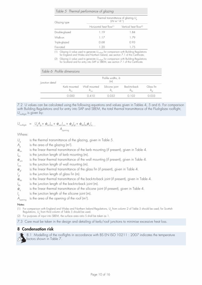
Table 5 Thermal performance of glazing
Glazing type
Thermal transmittance of glazing Ug(W·m–1·K–1)
Horizontal heat flow(1) Vertical heat flow(2)
Double-glazed 1.19 1.84
Walk-on 1.17 1.79
Triple-glazed 0.68 0.93
Fire-rated 1.20 1.75
(1) Glazing U value used to generate Urooflight for comparison with Building Regulations for England and Wales and Northern Ireland, see section 7.1 of this Certificate.
(2) Glazing U value used to generate Urooflight for comparison with Building Regulations for Scotland and for entry into SAP or SBEM, see section 7.1 of this Certificate.
Table 6 Profile dimensions
Junction detail
Profile widths, b(m)
Kerb mountedbkm
Wall mountedbwm
Silicone jointbsj
Back-to-backbbb
Glass finbgf
0.000 0.410 0.032 0.102 0.033
7.2 U values can be calculated using the following equations and values given in Tables 4, 5 and 6. For comparison with Building Regulations and for entry into SAP and SBEM, the total thermal transmittance of the Flushglaze rooflight, Urooflight is given by:
Urooflight = UgAg + �kmIkm + �wmIwm + �gfIgf + �bbIbb�sjIsjAopening
Where:
Ug is the thermal transmittance of the glazing, given in Table 5.Ag is the area of the glazing (m2).�km is the linear thermal transmittance of the kerb mounting (if present), given in Table 4.Ikm is the junction length of kerb mounting (m).�wm is the linear thermal transmittance of the wall mounting (if present), given in Table 4.Iwm is the junction length of wall mounting (m).�gf is the linear thermal transmittance of the glass fin (if present), given in Table 4.Igf is the junction length of glass fin (m).�bb is the linear thermal transmittance of the back-to-back joint (if present), given in Table 4.Ibb is the junction length of the back-to-back joint (m).�sj is the linear thermal transmittance of the silicone joint (if present), given in Table 4.Isj is the junction length of the silicone joint (m).Aopening is the area of the opening of the roof (m2).
Notes:(1) For comparison with England and Wales and Northern Ireland Regulations, Ug from column 2 of Table 5 should be used; for Scottish
Regulations, Ug from third column of Table 5 should be used.(2) For purposes of input into SBEM, the surface area ratio S shall be taken as 1.
7.3 Care must be taken in the design and detailing of kerb/roof junctions to minimise excessive heat loss.
8 Condensation risk 8.1 Modelling of the rooflights in accordance with BS EN ISO 10211 : 2007 indicates the temperature factors shown in Table 7.

Page 11 of 16
Table 7 Temperature factors (1)
Junction detailTemperature factor, fRsi
Kerb mounted Wall mounted Glass fin Back-to-back Silicone joint
Double-glazed 0.42 0.23 0.72 0.81 0.60
Walk-on 0.43 0.24 — 0.88 —
Triple-glazed 0.45 0.25 0.80 0.89 0.71
Fire-rated 0.44 — — — —
(1) The ratio of temperature drop between the internal rooflight surface and the external environment and the total temperature drop between internal and external environments.
8.2 The risk of condensation forming on an internal surface of the rooflight is dependent on its temperature and the temperature and humidity of the adjacent air. The minimum temperature factor is dependent on the building type, external temperature and external relative humidity for the location and can be calculated for a particular situation in accordance with BS EN ISO 13788 : 2012. Alternatively, default critical temperature factors for limiting the risk of surface condensation values can be obtained from BRE Information Paper IP 1/06.
8.3 Where the temperature factors given in Table 7 are less than the calculated or default values for the relevant building type, there is a risk of surface condensation forming. However, limited intermittent condensation, appearing initially on the kerb, will not be detrimental to the rooflight. By way of comparison, minimum temperature factors for typical PVC-U windows are between 0.50 and 0.65.
8.4 In all cases, the risk of surface condensation can be reduced by limiting activities which produce large amounts of moisture and by providing means for adequate ventilation.
9 Strength and stability 9.1 Tests have shown that resistance to imposed wind loads by the rooflights is dependent on size. As a guide, small rooflights are more resistant to imposed loads. Rooflights, therefore, should be selected according to the loads expected for a particular location and use. The loads must be designed by a suitably qualified and
experienced individual in accordance with the requirements of the national Buildings Regulations and Standards.
9.2 A rectangular walk-on rooflight was tested with a uniformly distributed load (UDL) of 1.5 kN·m–2 plus an ultimate positive pressure of 2500 Pa and a negative pressure of 1000 Pa. See Table 8 for an example of the allowable pressures.
Table 8 Resistance to wind loads (+UDL 1.5 kN·m–2)
Rooflight (mm) Ultimate downward pressure
(Pa)
Ultimate upward pressure
(Pa)
Allowable downward pressure(1)
(Pa)
Allowable upward
pressure(1)
(Pa)
3345 x 1492(2) 2500 1000 833 333
(1) Derived by applying a global safety factor of 3 on ultimate values.(2) Outer pane: toughened laminated glass outer pane comprising two 12 mm clear
toughened and heat soak tested panes laminated together with a 1.5 mm C.I.P. inert layer.
9.3 The magnitude of the actual snow load imposed will depend upon a number of factors, such as height above sea level, geographical location, roof arrangement and type of rooflights. Therefore, it is recommended that BS EN 1991-1-3 : 2003 and its National Annex is used to calculate the actual snow load. The appropriate
safety factors must be applied by the building designer.
9.4 The products can be selected to have adequate resistance to wind loads calculated in accordance with BS EN 1991-1-4 : 2005 and its National Annex.
10 Water resistance 10.1 Rooflights, when installed in accordance with the manufacturer’s instructions and sections 17 and 18 of this Certificate, will provide adequate resistance to the ingress of precipitation.
10.2 Particular attention must be paid to the correct fitting of all components. The roof waterproofing system must be carefully dressed up the kerb (outside the scope of this Certificate) to provide a watertight joint between the kerb and the roofdeck.
11 Behaviour in relation to fire 11.1 The glazing in the rooflights is Class A1 by reference to Commission Decision 96/603/EC and can therefore be considered as non-combustible.
11.2 When used, unwired glass at least 4 mm thick can be regarded as having an AA designation.

Page 12 of 16
11.3 A fire-rated Flushglaze rooflight measuring 1500 mm by 1500 mm(1) with a double-glazed glazing unit (6 mm clear toughened outer pane, 16 mm steel spacer, air-filled cavity and a 19 mm Pyrobel Low-E glass with soft coating) can be taken as having Insulation, E; 44 minutes and Integrity, I; 47 minutes and satisfies the integrity and insulation criteria, EI30, of BS EN 1363-1 : 1999 for a minimum period of 30 minutes.
12 Sound performanceA walk-on Flushglaze rooflight comprising two glazing units (33 mm low iron white, laminated, heat-soak tested toughened outer pane, 14 mm air cavity and 8.8 mm clear toughened laminated Low-E coated inner pane) joined with back-to-back angle support, when tested to BS EN ISO 140-3 : 1995, achieved Rw 41 dB.
13 Safety 13.1 Under no circumstances should anyone venture onto a rooflight except the walk-on products. If the rooflight is located on a roof generally accessible to the public, provision must be made to prevent people falling onto the glazed part (for example by use of for instance guard rails).
13.2 When subjected to normal conditions of use, movement of the structure, hygrothermal stresses, or vibrations, the rooflights will not collapse or result in falling debris that could cause injury to occupants or passers-by.
13.3 For walk-on Flushglaze rooflights, care must be taken when walking over the unit, especially in wet conditions and on clear glass. Slip resistant glass was tested to the method in The Assessment of Floor Slip Resistance, The UK Slip Resistance Guidelines, Issue 3 November 2005 (see Table 9).
Table 9 Slip resistance
Glass type Mean surface roughness Rtm(µm)
Pedestrian slip potential
Toughened with 8 mm non-slipfrit dots (40% coverage) 20 Moderate/low
Toughened, sandblasted 12 Moderate/low
14 Security against intrusion The sealant arrangement ensures that removal of the glass is difficult from the outside.
15 Maintenance 15.1 If damage occurs, the rooflights can be re-glazed, but this operation should be carried out using the materials recommended by the Certificate holder and approved by the BBA.
15.2 The sealant should be subject to regular inspection and maintenance and replaced if required.
15.3 Cleaning of the rooflight and frame should be carried out using water containing non-detergent soap. To avoid scratching of the surface, only soft cloths should be used when cleaning.
15.4 The external surface of the rooflights cannot be cleaned from the inside of the building. For maintenance and cleaning purposes, special precautions must be taken such as the provision of a catwalk, to allow safe access and to prevent the possibility of falling through the glazing unit.
16 Durability 16.1 Subject to suitable maintenance of the complete rooflight and in particular of the sealant (see section 15.2), the products, when installed in accordance with this Certificate, will have a life of at least 20 years in non-corrosive environments.
16.2 Any slight external colour change or surface dulling of the frame that might occur will be uniform over the visible surfaces of the frame.
Installation
17 General 17.1 Installation of the Flushglaze Rooflights should be carried out in accordance with the Certificate holder’s installation instructions.
17.2 Prior to installation of the rooflight, the roof must be checked by means of calculations or testing to ensure that it can carry the additional loads the installation may impose. The roof must be strengthened as necessary to support the rooflight. This work must be carried out by a suitably qualified and experienced individual.
17.3 The rooflight should be checked dimensionally to ensure fit before the unit is lifted to the roof.
17.4 The kerbs (outside the scope of this Certificate) should be checked for specification and dimensional accuracy. Kerbs should be complete and fully weathertight prior to installation. The correct fall must be built into the kerb to avoid

Page 13 of 16
ponding. Information can be obtained from the Certificate holder. The Certificate holder recommends a trial fitting prior to the final installation to ensure correct fit as it becomes extremely difficult to move the units once bonded.
17.5 Multipart units must not be installed in wet conditions as the site-applied sealant must be applied in dry conditions and temperatures above 5°C. Single units can be installed in wet conditions but care must be taken in handling them.
Wall abutted units17.6 If the rooflight has a wall abutment, a suitable lead flashing (outside the scope of this Certificate) will be required over the abutment following installation. It is recommended that any chasing of brickwork for flashings is completed prior to installation.
17.7 Temporary battens must be secured to the wall to support the weight of the unit during installation. The battens must be installed in line with the kerbs and removed when installation is complete.
Trial and final fitting17.8 When installing multipart units, an end section is installed first. If there is a wall abutment positioned along the span, this section must be installed first.
17.9 The first section is lowered into place. Any Flushglaze frame edges must overhang the kerb equally (nominal 22 mm to outer edge of unit) and any wall abutments between 5 mm to 10 mm from the wall face.
17.10 For multipart units, the next section of the unit is lowered into place. The frames have unique identifications to ensure correct installation (on units without back-to-back angle supports, the identification is located on the underside of the Flushglaze frame).
17.11 Each frame section is aligned with its adjacent frame using the splice plates supplied (except for wall abutments). This step is repeated for all the sections of the multipart unit.
17.12 When all sections are in place, the centre lines are marked with a pencil onto the kerb/wall. These marks are used to reposition the unit during the final installation.
17.13 Two runs of structural adhesive tape are placed around the underside of all frame sections. Units with wall abutment angle or back-to-back support angles do not require structural adhesive tape. For fire-rated units, one line of ceramic tape and one line of fire-rated silicone are used.
17.14 Expanding foam tape is applied to the underside of glass along all edges (except for fire-rated units).
17.15 Steps in sections 17.12 to 17.14 are repeated to seal the frames to the kerb.
17.16 The Flushglaze frames are secured to the kerb and the wall (outside the scope of this Certificate).
For glass fin installation17.17 The edge of the Flushglaze frame/wall abutment detail is marked to locate the centre line of the first glass fin and operations described in sections 17.14 and 17.15 are repeated.
17.18 The glazing units are removed from the kerb/wall.
17.19 A distance of 75 mm is measured to the left of each centre datum line and is marked off on the wall/kerb representing the location for the left-hand edge of the support bracket. The top edge of the back plate of the support bracket should be level with the top surface of the kerb.
17.20 Two brackets, an upper and a lower (angled), per fin are used for glass fins positioned along the pitch. For glass fins positioned across the pitch two right angled brackets are used.
17.21 For brackets mounted to kerbs, the appropriate support bracket is selected and positioned so that the left-hand edge is positioned next to the mark produced in section 17.20 and the top of the bracket sits flush with the kerb. A small pilot hole is drilled for each screw fixing in the kerb and the bracket is fastened to the kerb using woodscrews (outside the scope of this Certificate) and plastic horseshoe packers, ensuring a nominal 5 mm gap from the kerb. This step is repeated for all kerb mounted brackets.
17.22 For brackets mounted under the wall abutment, the appropriate support bracket is selected and is positioned so that the left-hand edge is positioned next to the mark produced in section 17.20 and the top of the bracket sits flush with the top edge of the wooden batten (installed earlier). A hole is drilled for each screw fixing, to suit the wall plugs. The bracket is fastened to the wall using the screws with wall plugs and plastic horseshoe packers ensuring a nominal 5 mm gap from the wall. This step is repeated for all wall mounted brackets.
17.23 When all brackets are fixed to the walls, they are lined with rubber (3 mm thick) and the glass fins are placed inside them.
17.24 If the glass fins have any notches these must be placed upwards (underneath, where wall abutments are present) to avoid any contact with Flushglaze frame. A series of packers (8 mm thick) is placed across the top of the glass fin at a maximum of 600 mm centres, held in place with silicone to prevent glass to glass contact.
17.25 Two runs of butyl tape are placed around the underside of all the frame sections. Units with wall abutment angle or back-to-back support angles do not require butyl tape. For fire-rated units, one line of ceramic tape and one line of fire-rated silicone are used.
17.26 Expanding foam tape is applied to the underside of glass along all edges resting on the kerb (except for fire-rated units) and the frames are sealed to the kerb.

Page 14 of 16
17.27 For multipart units with back-to-back angle support, the angles are locked together using counter sunk fixings.
17.28 The Flushglaze frame is fixed with woodscrews (outside the scope of this Certificate) and the wall abutment with screws and wall plugs/expanding Hilti bolts (for walk-on units, outside the scope of this Certificate), if applicable, ensuring that sufficient horseshoe packers are placed between the kerb/wall and the framework to provide support and prevent frame distortion around each screw fixing.
17.29 For glass fin supported joints, the plastic packers can be twisted to run parallel with the top of the glass fin. A run of matt black silicone is applied along the fin’s length between the top of the fin and the underside of the glass to cover the plastic packers.
17.30 When the unit has been securely screwed to the kerb, length(s) of polyethylene backing rod are cut to fit the space between the sections of glass and are pressed into the space and positioned 8 mm below the outer surface of the glass. Silicone is applied to overfill the space and the excess silicone removed to finish the joint. The edges of the frames must sit flush and further silicone is applied, if required.
17.31 When the units are secured in place, clip-on covers are fitted over the wall abutments. Insulation (outside the scope of this Certificate) is fitted behind the covers and the clip feature is installed by first engaging the top leg then rotating to engage the bottom leg, clicking into place and tapping it gently with a rubber mallet to ensure a secure fit.
17.32 The end plates are bonded into place and any kerb fixing covers are clipped-on by first engaging the top leg and then rotating into place.
17.33 Finally a lead flashing (outside the scope of this Certificate) is fitted over any wall abutments.
Technical Investigations
18 Tests 18.1 Tests were carried out to determine: • air permeability• watertightness• durability of sealants• resistance to intrusion• resistance to cyclic loads.
18.2 The polyester powder-coating on the aluminium frame was tested to determine:• resistance to artificial weathering• gloss retention after artificial weathering• resistance to salt spray• adhesion to substrate• resistance to humidity• resistance to scratching• resistance to sulfur dioxide.
19 Investigations 19.1 The manufacturing process was evaluated, including the methods adopted for quality control, and details were obtained of the quality of components used.
19.2 Assessments and test reports were evaluated relating to:• fire performance of the fire-rated rooflights• weathertightness• slip resistance.
19.3 Equations for calculating the U values of the rooflights from individual components were generated.
19.4 Thermal performance and temperature factors of glazed rooflights were assessed using thermal simulation with reference to BS EN ISO 10077-2 : 2012, BS EN ISO 10211 : 2007 and BRE Report BR 497 : 2007. Thermal transmittance of the glazing was assessed using BS EN 673 : 2011.
19.5 A user survey was conducted.

Page 15 of 16
BibliographyBS EN 673 : 2011 Glass in building — Determination of thermal transmittance (U value). Calculation method
BS EN 1991-1-3 : 2003 Eurocode 1 — Actions on structures — General actions NA to BS EN 1991-1-3 : 2003 UK National Annex to Eurocode 1 — Actions on structures — General actions BS EN 1991-1-4 : 2005 Eurocode 1 — Actions on structures — General actions NA to BS EN 1991-1-4 : 2005 UK National Annex to Eurocode 1 — Actions on structures —General actions BS EN 1363-1 : 1999 Fire resistance tests — General requirements BS EN ISO 140-3 : 1995 Acoustics — Measurement of sound insulation in buildings and of building elements — Laboratory measurement of airborne sound insulation of building elements BS EN ISO 9001 : 2008 Quality management systems — Requirements BS EN ISO 10211 : 2007 Thermal bridges in building construction — Heat flows and surface temperatures — Detailed calculations BS EN ISO 10077-2 : 2012 Thermal performance of windows, doors and shutters — Calculation of thermal transmittance — Numerical method for frames BS EN ISO 13788 : 2012 Hygrothermal performance of building components and building elements — Internal surface temperature to avoid critical surface humidity and interstitial condensation —Calculation methods BRE Information Paper IP 1/06 Assessing the effects of thermal bridging at junctions and around openingsBRE Report (BR 497 : 2007) Conventions for calculating linear thermal transmittance and temperature factors

Page 16 of 16
Conditions of Certification
20 Conditions20.1 This Certificate:• relates only to the product/system that is named and described on the front page• is issued only to the company, firm, organisation or person named on the front page — no other company, firm,
organisation or person may hold or claim that this Certificate has been issued to them• is valid only within the UK• has to be read, considered and used as a whole document — it may be misleading and will be incomplete to be
selective• is copyright of the BBA• is subject to English Law.
20.2 Publications, documents, specifications, legislation, regulations, standards and the like referenced in this Certificate are those that were current and/or deemed relevant by the BBA at the date of issue or reissue of this Certificate.
20.3 This Certificate will remain valid for an unlimited period provided that the product/system and its manufacture and/or fabrication, including all related and relevant parts and processes thereof:• are maintained at or above the levels which have been assessed and found to be satisfactory by the BBA• continue to be checked as and when deemed appropriate by the BBA under arrangements that it will determine• are reviewed by the BBA as and when it considers appropriate.
20.4 The BBA has used due skill, care and diligence in preparing this Certificate, but no warranty is provided.
20.5 In issuing this Certificate, the BBA is not responsible and is excluded from any liability to any company, firm, organisation or person, for any matters arising directly or indirectly from:• the presence or absence of any patent, intellectual property or similar rights subsisting in the product/system or any
other product/system• the right of the Certificate holder to manufacture, supply, install, maintain or market the product/system• actual installations of the product/system, including their nature, design, methods, performance, workmanship and
maintenance• any works and constructions in which the product/system is installed, including their nature, design, methods,
performance, workmanship and maintenance• any loss or damage, including personal injury, howsoever caused by the product/system, including its manufacture,
supply, installation, use, maintenance and removal• any claims by the manufacturer relating to CE marking.
20.6 Any information relating to the manufacture, supply, installation, use, maintenance and removal of this product/system which is contained or referred to in this Certificate is the minimum required to be met when the product/system is manufactured, supplied, installed, used, maintained and removed. It does not purport in any way to restate the requirements of the Health and Safety at Work etc. Act 1974, or of any other statutory, common law or other duty which may exist at the date of issue or reissue of this Certificate; nor is conformity with such information to be taken as satisfying the requirements of the 1974 Act or of any statutory, common law or other duty of care.
British Board of Agrément tel: 01923 665300Bucknalls Lane fax: 01923 665301Watford e-mail: [email protected] WD25 9BA website: www.bbacerts.co.uk©2013