Disruption Mitigation System Developments and Design · PDF fileDisruption Mitigation System...
27
Disruption Mitigation System Developments and Design for ITER L.R. Baylor, C. Barbier, N.D. Bull, J.R. Carmichael, M.N. Ericson, M.S. Lyttle, S.J. Meitner, D.A. Rasmussen, G. Kiss * , S. Maruyama * 25 th IAEA Fusion Energy Conference St. Petersburg, Russia Oak Ridge National Laboratory * ITER Organization
-
Upload
phungnguyet -
Category
Documents
-
view
237 -
download
3
Transcript of Disruption Mitigation System Developments and Design · PDF fileDisruption Mitigation System...

Disruption Mitigation System
Developments and Design
for ITER
L.R. Baylor, C. Barbier, N.D. Bull,
J.R. Carmichael, M.N. Ericson, M.S. Lyttle,
S.J. Meitner, D.A. Rasmussen,
G. Kiss*, S. Maruyama*
25th IAEA Fusion Energy Conference St. Petersburg, Russia
Oak Ridge National Laboratory *ITER Organization

Outline
• DMS Requirements
• DMS Design for ITER
• Design Challenges
• Design Progress-to-Date
• Summary
Disruption Mitigation 2

• Large Thermal Loads occur during Thermal Quench – TQ peak heat loads need reduction of > 10 X
• Large Mechanical Loads on plasma facing components and vessel during Current Quench - CQ decay time must be controlled within limits of 50-150 ms
• Runaway electrons can be generated during Current Quench - RE current must be suppressed or dissipated to less than 2 MA
• Mitigate with solid and gas injection of deuterium, argon, neon and helium
• Developing tools and techniques for:
- Massive gas injection (MGI)
- Shattered pellet injection (SPI)
Mitigation of Disruptions is a
Challenge for ITER
Thermal Quench
Current Quench
Runaway Electrons
Ip
Wp
Burning Plasma
Disruption Precursor
Preventive SPI and MGI of material for Thermal Mitigation and Runaway
Electron Suppression
MGI and SPI RE Dissipation
Disruption Mitigation 3

Disruption Mitigation System Material
Injection Requirements
Disruption Mitigation 4
Massive Gas Injection Valve Concept
DMS Requirements: Deliver rapid
shattered pellet and massive gas
injection systems to
• Limit impact of plasma disruption
thermal and mechanical loads on
walls and vacuum vessel – up to 10
kPa-m3 of D2, Ar, Ne, He in < 20
ms
• Suppress the formation and effects
of high energy runaway electrons –
up to 100 kPa-m3 in < 10 ms
• Reliability and Maintainability
• Are these requirements compatible? Shattered Pellet Injector Concept

Disruption Mitigation System
Configuration
DMS Configuration:
• Shattered pellet injector (SPI) or
Massive gas injection (MGI)
located in 3 upper ports with pellet
shattered near plasma edge
• SPI has multiple barrels for
redundancy and adjusting amount
injected – can be used as MGI
• MGI or SPI located in 1 equatorial
port for runaway electron
mitigation
• Combinations of MGI and SPI are
possible
Disruption Mitigation 5
or MGI
or SPI
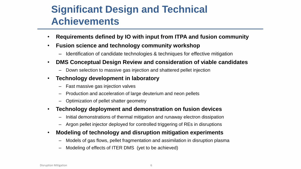
Significant Design and Technical
Achievements
• Requirements defined by IO with input from ITPA and fusion community
• Fusion science and technology community workshop
– Identification of candidate technologies & techniques for effective mitigation
• DMS Conceptual Design Review and consideration of viable candidates
– Down selection to massive gas injection and shattered pellet injection
• Technology development in laboratory
– Fast massive gas injection valves
– Production and acceleration of large deuterium and neon pellets
– Optimization of pellet shatter geometry
• Technology deployment and demonstration on fusion devices
– Initial demonstrations of thermal mitigation and runaway electron dissipation
– Argon pellet injector deployed for controlled triggering of REs in disruptions
• Modeling of technology and disruption mitigation experiments
– Models of gas flows, pellet fragmentation and assimilation in disruption plasma
– Modeling of effects of ITER DMS (yet to be achieved)
Disruption Mitigation 6

• CDR complete
• Design underway for
– Massive gas injection (MGI)
– Shattered cryogenic pellet injection (SPI)
• Hardware for SPI and MGI subsystems must be tested on fusion
experiments to determine effectiveness
– Experiments are performed by fusion community with their resources
– Initial tests of DMS techniques and technologies for ITER underway in
lab and at DIII-D
– U.S. ITER and VLT supports SPI and MGI experiments with hardware
– Simulations to determine effectiveness on ITER are needed
Disruption Mitigation System
Design Status and Plans
Disruption Mitigation 7

Outline
• DMS Requirements
• DMS Design for ITER
• Design Challenges
• Design Progress-to-Date
• Summary
Disruption Mitigation 8

MGI Integrated Mass Flow into Plasma for
Different Gases/Distances
Disruption Mitigation 9
28mm valve orifice and tube I.D. 2 kPa-m3 in reservoir Ideal opening valve assumed.
Time (s)
kP
a-m
3
• Calculations for Ne and D2 with a 28mm valve/tube size
• D2 and Ne at 1m achieves the 90% injection within 20ms – the specified response TM cannot be achieved with neon MGI at 4m, 60% is possible
CFD calculations – SonicFOAM
TM RE
Distance from the plasma

MGI and SPI for RE Suppression/Dissipation
Installed Inside Equatorial Port Plug to Meet
Injection Time Requirements
MGI and SPI DMS
• MGI located in one equatorial port plug for runaway electron suppression/dissipation
to meet injection time requirement - limited by sound speed of gas
• Combination of SPI and MGI is possible
• Design challenges with active MGI components located inside port plug
Up to 100 kPa-m3 for runaway electron
suppression and dissipation
MGI fast gas valves use a
stainless steel valve seat with
Vespel polyimide plugs
Disruption Mitigation 10
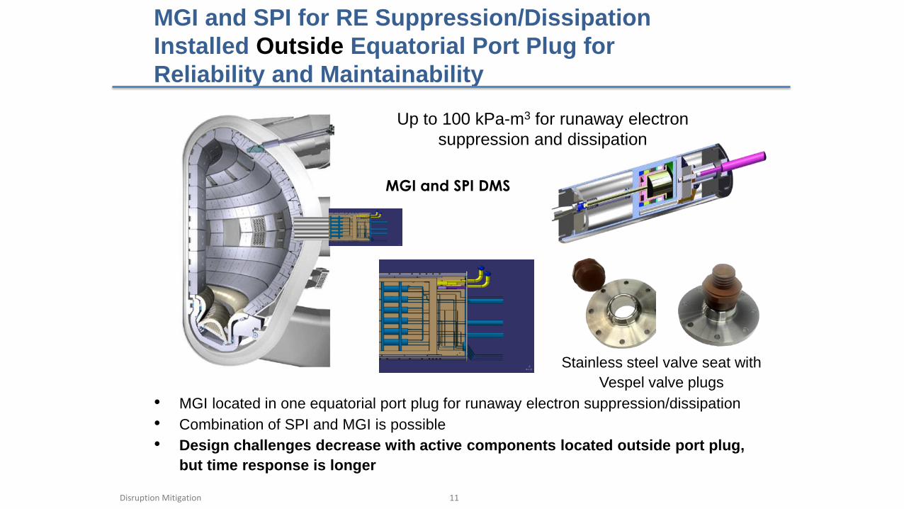
MGI and SPI for RE Suppression/Dissipation
Installed Outside Equatorial Port Plug for
Reliability and Maintainability
MGI and SPI DMS
• MGI located in one equatorial port plug for runaway electron suppression/dissipation
• Combination of SPI and MGI is possible
• Design challenges decrease with active components located outside port plug,
but time response is longer
Up to 100 kPa-m3 for runaway electron
suppression and dissipation
Stainless steel valve seat with
Vespel valve plugs
Disruption Mitigation 11

Shattered Cryogenic Pellet Injection Active
Components Installed Outside Upper Port Plugs
for Reliability and Maintainability
Cryostat (Radiation Shields
not shown) VAT Valve
Guide Tube
Pellet Collection Funnel
Propellant Valve
• SPI located in upper port plug(s) with pellet shattered near plasma edge
• Injector has multiple barrels for redundancy and adjusting amount injected –
combination of MGI and SPI is possible
• Challenges decrease with active SPI components located outside port plug
• Injection time is marginal to meet 20ms requirement for TM
Single shot SPI pellets frozen in
short cold section of guide tube
Injector has multiple barrels
Combination of MGI and SPI is possible
Disruption Mitigation 12

Outline
• DMS Requirements
• DMS Design for ITER
• Design Challenges
• Design Progress-to-Date
• Summary
Disruption Mitigation 13

Massive Gas Injection Valve Prototype
Disruption Mitigation
Valve based on a design used on JET, but modified for ITER tokamak environment and injection requirements. MGI Valve uses Flyer Plate to Achieve Fast Opening Time and incorporates T compatible components
14

Design, Fab and Test of MGI Power
Supply Completed
Disruption Mitigation 15
Filter Module
Fuse
FuseNC Switch
24VPower Supply
HVPower Supply
Control PCB
Digital/Manual Switch
NC =Digital
Panel Door
HV Meter
Thyristor
S1
NO Switch
NC
Sw
itch
S2
Insulated Electrical Leads
ManualTrigger Pulse
DK#: Z1300-ND
M#
: 64
2-Q
16
P1
BX
XR
24
E
USBPower Supply
NIUSB-6353
DC_ctrl
USB Interface
HV Adjust
DK#: 450-1704-NDPOT DK#: 3540S-1-203L-ND
Key:
- On front Panel of Cabinet
- Inside CabinetDK#: EG4748-ND
Front Panel Switch
AC Switchw/LED
DK#: 432-1285-ND
Front Panel Switch
HV Switchw/LED
DK#: 432-1285-ND
SCR Triggering Requirements:
• ~5V, ~300mA, ~100ms duration
• ~15 ohm load
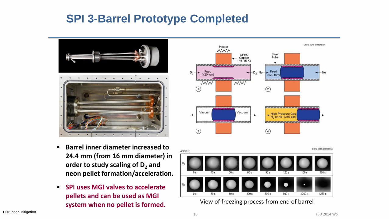
SPI 3-Barrel Prototype Completed
Disruption Mitigation 16 TSD 2014 WS
• Barrel inner diameter increased to 24.4 mm (from 16 mm diameter) in order to study scaling of D2 and neon pellet formation/acceleration.
• SPI uses MGI valves to accelerate pellets and can be used as MGI system when no pellet is formed. View of freezing process from end of barrel

25 mm D2 and Neon Pellets Formed and
Accelerated from 3 Barrels
Disruption Mitigation 17 TSD 2014 WS
• 3 ea. ~ 25 mm pellets formed and accelerated to 330 m/s
• 1.5 kPa-m3 of deuterium each. 2 pellets exceed the requirement of 2 kPa-m3 for thermal mitigation
• Future testing planned for 34mm diameter pellets for RE suppression
25 mm neon
25 mm D2
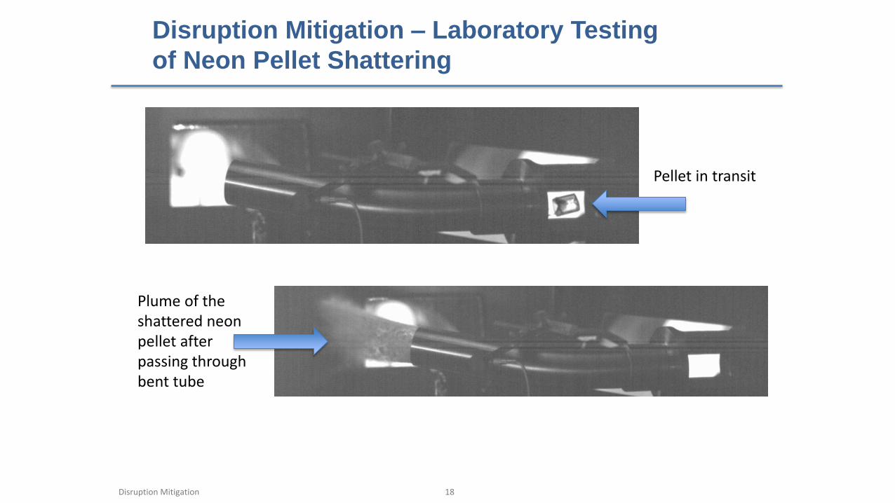
Disruption Mitigation – Laboratory Testing
of Neon Pellet Shattering
Disruption Mitigation 18
Plume of the shattered neon pellet after passing through bent tube
Pellet in transit
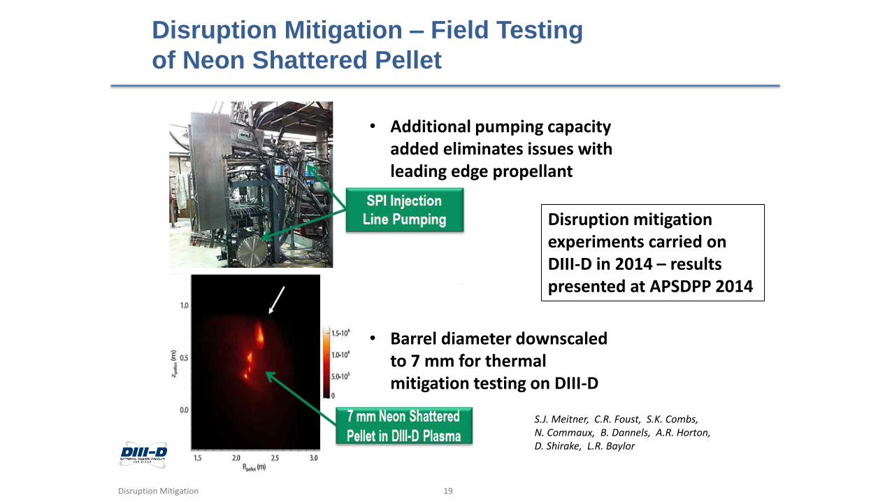
Disruption Mitigation – Field Testing
of Neon Shattered Pellet
Disruption Mitigation 19
• Additional pumping capacity added eliminates issues with leading edge propellant
• Barrel diameter downscaled to 7 mm for thermal mitigation testing on DIII-D
S.J. Meitner, C.R. Foust, S.K. Combs, N. Commaux, B. Dannels, A.R. Horton, D. Shirake, L.R. Baylor
Disruption mitigation experiments carried on DIII-D in 2014 – results presented at APSDPP 2014
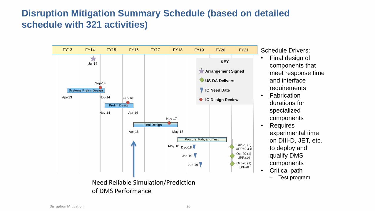
Disruption Mitigation Summary Schedule (based on detailed
schedule with 321 activities)
Disruption Mitigation 20
Schedule Drivers:
• Final design of
components that
meet response time
and interface
requirements
• Fabrication
durations for
specialized
components
• Requires
experimental time
on DIII-D, JET, etc.
to deploy and
qualify DMS
components
• Critical path – Test program
Apr-16 May-18
Final Design
Jul-14
Apr-13 Nov-14
Systems Prelim Design
FY13 FY14 FY15 FY16 FY17 FY18 FY19 FY20
KEY
Arrangement Signed
US-DA Delivers
IO Need Date
IO Design Review
Oct-20 (2)
UPP#2 & 8May-18
Oct-20 (1)
EPP#8
Sep-14
Nov-14 Apr-16
Prelim Design
Feb-16
Nov-17
FY21
Oct-20 (1)
UPP#14
Dec-18
Jan-19
Jun-19
Procure, Fab, and Test
Need Reliable Simulation/Prediction of DMS Performance

Summary
• DMS scope and schedule are well defined and being executed
– CDR Complete
– Down selection to SPI and MGI following December 2012 CDR
– Hardware for candidate SPI and MGI being designed, fabricated and tested
– International fusion community is actively engaged
– Design and qualification integrated with DMS research partners
• Present Challenges - Injection response vs Reliability
– Harsh port plug environment and reliability requirements
– Minimum response time for runaway electron suppression and dissipation
• More simulation and modeling needed to resolve requirement issues
– Needed for Final Design of DMS
Disclaimer:
The views and opinions expressed in this paper do not necessarily reflect those of the ITER Organization.
Disruption Mitigation 21

Disruption Mitigation 22 IAEA 2014

BACKUP ONLY
Disruption Mitigation 23 TSD 2014 WS

Milestone: Complete Disruption Mitigation System PDR
(November 2014)
Disruption Mitigation 24
Pre-SPDR tasks and responsible parties
• IO completes physics studies to determine maximum allowable response time
• IO completes PCR to reserve space for outside of the port plug location
• Tokamak experiments and IO analysis provide guidance on MGI vs SPI material
assimilation, TQ, CQ and RES effectiveness and need for multiple toroidal and/or
poloidal injection locations
• US completes P&IDs for MGI and SPI options
• US performs 3-barrel injector tests
• US determine the maximum obtainable pellet speed
• US completes the design, fabrication and initial testing of the MGI valve
• US completes the design and fabricate MGI valve firing electronics
SPDR Outcomes
• Most promising DM technology identified at SPDR becomes basis for remaining PD
and port plug interfaces
• Backup DM technology design placed on hold and minimum hardware and design
needed for associated port plugs
• Update Systems Requirements to reflect latest physics and hardware understanding

Closing gas
volume
Pancake coil Bellows
sealed stem
Flyer
plate
Disruption mitigation
gas reservoir
Valve
seat
Vespel
stem tip
Massive Gas Injection Valve
Prototype
Disruption Mitigation
Valve based on a design used on JET but modified for ITER tokamak environment and injection rate requirements. Modified Valve uses Flyer Plate to Achieve Fast Opening Time and incorporates T compatible components
25 TSD 2014 WS
Full size - 8 kPa*m3 injected gas mass

Massive Gas Injection on DIII-D
Disruption Mitigation 26 TSD 2014 WS

Disruption Mitigation Includes Injection of Pellets
Shattered at Plasma Edge and Gas Injection through
Delivery Tubes
SPI located in upper
port plugs with pellet
shattered near
plasma edge
MGI located in
equatorial port plugs
• Mitigate impact of the disruption thermal and current quench
– Use large shattered pellets composed of neon with a deuterium shell
• Suppress and dissipate runaway electrons
– Use massive gas or shattered pellet injection
Disruption Mitigation 27