Disruption mitigation in ITER - University of Texas at...
18
Disruption mitigation in ITER, Sherwood conf, May 2, 2011 Page 1 Disruption mitigation in ITER S.Putvinski, R.Pitts, M.Sugihara, L.Zakharov
Transcript of Disruption mitigation in ITER - University of Texas at...

Disruption mitigation in ITER, Sherwood conf, May 2, 2011 Page 1
Disruption mitigation in ITER
S.Putvinski, R.Pitts, M.Sugihara, L.Zakharov

Disruption mitigation in ITER, Sherwood conf, May 2, 2011 Page 2
Outline
• Introduction• Massive gas injection for mitigation of thermal loads• Forces on VV and in vessel components• Suppression of runaway electrons• Conclusions

Disruption mitigation in ITER, Sherwood conf, May 2, 2011 Page 3
Introduction
• ITER vacuum vessel and in-vessel components are designed mechanically to withstand EM loads from the expected 2600 “typical” 15 MA disruptions (current quench time 50-150 ms) and 400 “typical” VDE
• However, local thermal loads during plasma disruptions significantly (10 times!) exceed melting threshold of divertor targets and FW panels
• A reliable Disruption Mitigations System (DMS) must be developed and installed in ITER prior to the full scale operation which will start in 2022. Presently it is at conceptual design phase

Disruption mitigation in ITER, Sherwood conf, May 2, 2011 Page 4
Introduction (2)
H-mode
L-mode
CQ
TQ
Plasma current
Plasma energy
RE current
t
Typical chain of events during plasma disruption
• The largest thermal loads occur during Thermal Quench
• Major mechanical forces act on plasma facing components during Current Quench
• Runaway electrons can be generated during Current Quench

Disruption mitigation in ITER, Sherwood conf, May 2, 2011 Page 5
MGI can to re-radiate most of plasma thermal energy
• Challenge for ITER DMS: re-radiate ~300 MJ of plasma thermal energy in about 3 ms and distribute it uniformly over FW
• Experimental results from present tokamaks with pre-emptive injection of high Z gases are very encouraging
– ASDEX-Upgrade 60-100% G.Pautasso, Pl.Phys,2009– Alcator C-mod ~75% R.S. Granetz, NF 2007– JET ~ 90% M.Lehnen, ITPA 2011M. Lehnen, IAEA 2010
E.Hollmann, NF 2008
Disruption mitigation in ITER, Sherwood conf, May 2, 2011 Page 6
0 1 2 3 40
20
40
60
80
100
20cm
10cm
r = 40cm
N Ne (1022)
Q r
ad (%
)
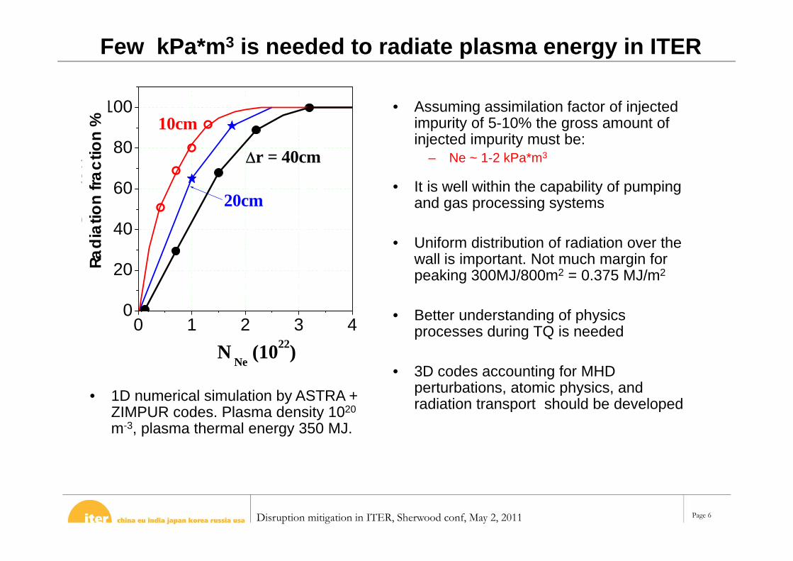
Few kPa*m3 is needed to radiate plasma energy in ITER
• Assuming assimilation factor of injected impurity of 5-10% the gross amount of injected impurity must be:
– Ne ~ 1-2 kPa*m3
• It is well within the capability of pumping and gas processing systems
• Uniform distribution of radiation over the wall is important. Not much margin for peaking 300MJ/800m2 = 0.375 MJ/m2
• Better understanding of physics processes during TQ is needed
• 3D codes accounting for MHD perturbations, atomic physics, and radiation transport should be developed
Radi
atio
n fra
ctio
n %
• 1D numerical simulation by ASTRA + ZIMPUR codes. Plasma density 1020
m-3, plasma thermal energy 350 MJ.

Disruption mitigation in ITER, Sherwood conf, May 2, 2011 Page 7
Forces impose constrain on maximum amount of gas
• The major EM loads on the VV and in vessel components occur during current quench of a disruption and following plasma VDE
• DMS goal is to transform very short and very long CQ into disruptions with CQ time 50-150 ms
10 50 100 500 CQ(ms)
DMS goal
Disruption mitigation in ITER, Sherwood conf, May 2, 2011 Page 8
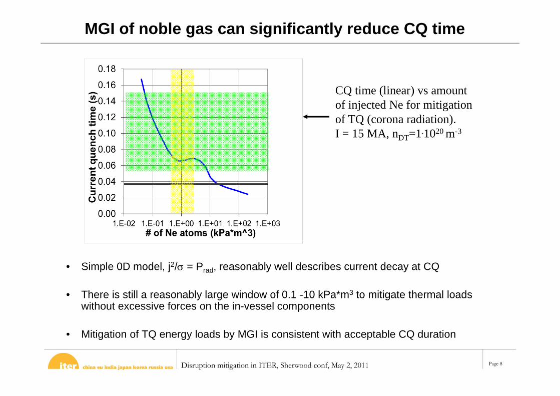
MGI of noble gas can significantly reduce CQ time
• Simple 0D model, j2/ = Prad, reasonably well describes current decay at CQ
• There is still a reasonably large window of 0.1 -10 kPa*m3 to mitigate thermal loads without excessive forces on the in-vessel components
• Mitigation of TQ energy loads by MGI is consistent with acceptable CQ duration
CQ time (linear) vs amount of injected Ne for mitigation of TQ (corona radiation). I = 15 MA, nDT=1.1020 m-3
Disruption mitigation in ITER, Sherwood conf, May 2, 2011 Page 9
Better understanding CQ plasmas is needed
• Plasma parameters during CQ: n= 1 1020 m-3, T = 10 eV, CQ ~ 40 ms
• Ion and electron mean free path in CQ plasmas: i ~e ~1 cm
• Pressure equilibration time along the field lines: p ~2R/Cs ~ 1 ms -> pressure is constant along magnetic field lines.
• Temperature equilibration time: ~ L2/ > 100 ms! Temperature and, hence, electrical resistance can be not constant on magnetic surface after MGI
• Variation of plasma resistivity will result in electrostatic perturbations E = E0 – gradand magnetic perturbations. How long does it takes for them to decay?
Disruption mitigation in ITER, Sherwood conf, May 2, 2011 Page 10
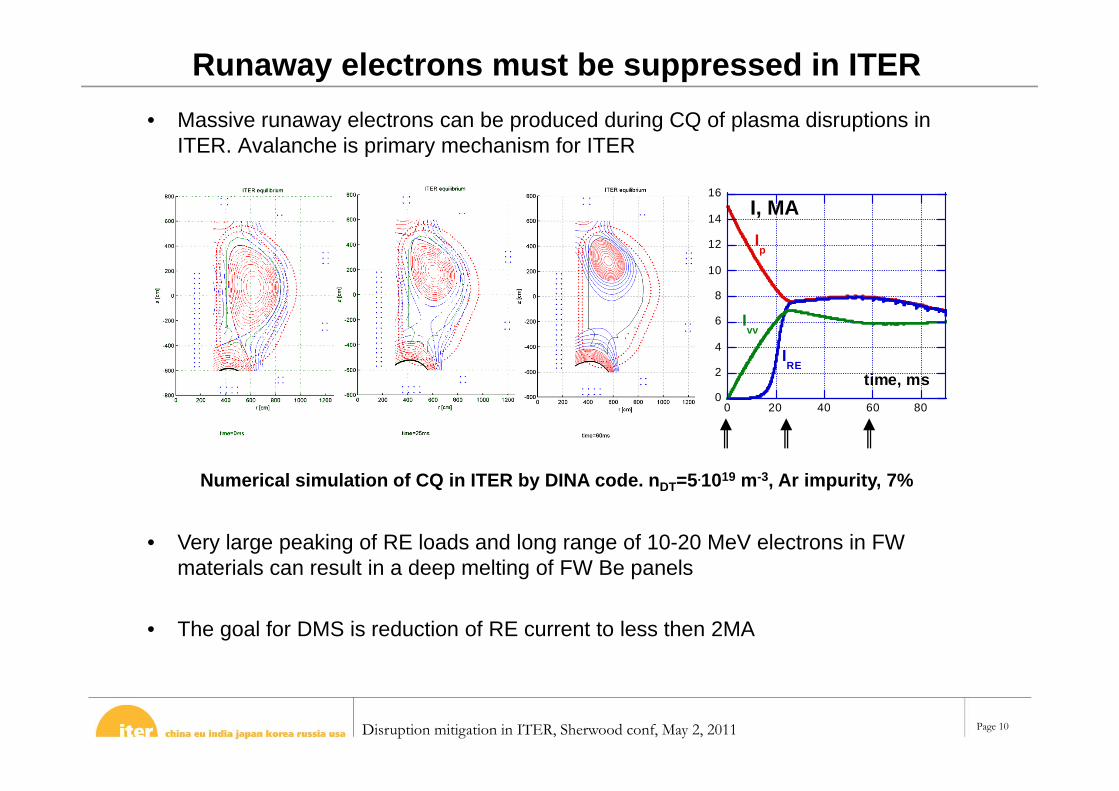
Runaway electrons must be suppressed in ITER• Massive runaway electrons can be produced during CQ of plasma disruptions in
ITER. Avalanche is primary mechanism for ITER
• Very large peaking of RE loads and long range of 10-20 MeV electrons in FW materials can result in a deep melting of FW Be panels
• The goal for DMS is reduction of RE current to less then 2MA
0
2
4
6
8
10
12
14
16
0 20 40 60 80
I, MA
time, ms
Ip
IRE
Ivv
Numerical simulation of CQ in ITER by DINA code. nDT=5.1019 m-3, Ar impurity, 7%
Disruption mitigation in ITER, Sherwood conf, May 2, 2011 Page 11
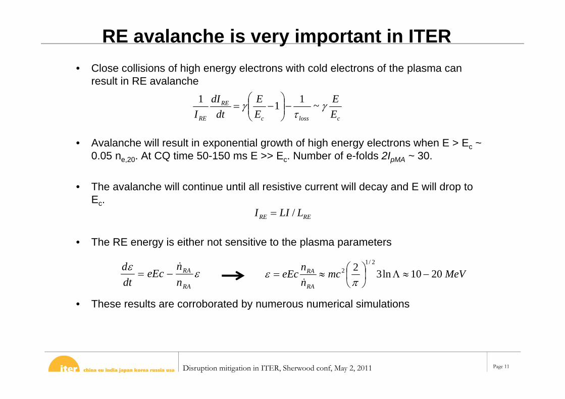
RE avalanche is very important in ITER• Close collisions of high energy electrons with cold electrons of the plasma can
result in RE avalanche
• Avalanche will result in exponential growth of high energy electrons when E > Ec ~ 0.05 ne,20. At CQ time 50-150 ms E >> Ec. Number of e-folds 2IpMA ~ 30.
• The avalanche will continue until all resistive current will decay and E will drop to Ec.
• The RE energy is either not sensitive to the plasma parameters
• These results are corroborated by numerous numerical simulations
clossc
RE
RE EE
EE
dtdI
I
~111
RA
RA
nneEc
dtd
MeVmcnn
eEcRA
RA 2010ln32 2/12
RERE LLII /

Disruption mitigation in ITER, Sherwood conf, May 2, 2011 Page 12
RE current has to be reduced to < 2 MA
• Kinetic energy of RE scales as IRE and is expected to be ~10 MJ at IRE~10 MA. Magnetic energy of RE scales as IRE
2 and is about 200 MJ
• The critical question: how much magnetic energy will be transferred to RE kinetic energy during CQ?
• Results of analysis of experimental data from JET (A.Loarte et.al. 2011) suggest that up to 40% of magnetic energy have been transferred in some shots
• More theoretical and experimental work is needed to resolve this uncertainty
Total energy of RE as function of RE current. Average electron energy = 12 MeV and li = 1 for the RE current

Disruption mitigation in ITER, Sherwood conf, May 2, 2011 Page 13
Collisional suppression of RE is challenging in ITER
• Avalanche can be suppressed by: – increase of electron density to enhance collisional slow down of RE– enhancement of RE loss, loss<1
• Reaching critical density will likely be above capability of the machine
• Collisional suppression might work if RE will be suppressed at density 30-50% of Rosenbluth’s density
Ratio Ec/E as function of Ne amount in the plasma (red). CQ time
is also shown (blue)

Disruption mitigation in ITER, Sherwood conf, May 2, 2011 Page 14
Suppression of RE electrons by repetitive gas jets• Large magnetic perturbations and secondary disruptions can be produced by dense
gas jets injected repetitively in the CQ plasma
• Required gas pressure in the jet ~ 1 atm, gas amount ~1 kPa*m3, 5-6 jets during CQ (staggered in time by >= 5 ms ).
• Based on estimates the total amount of gas can be 10 times less then for collisional damping!
• R&D is in progress to test this scheme in Tore-Supra, ASDEX-U, T-10.
CQ
TQ
Plasma current
RE current
tDense and resistive gas jet contracts current channel

Disruption mitigation in ITER, Sherwood conf, May 2, 2011 Page 15
Triggering MHD by contracting current profile
• Cylindrical geometry, ideal wall at b = 1.3a, low m modes• Current profile changed by introduction of high resistivity at the plasma
edge. Skin current added to the edge of current channel to conserve flux at the moving edge
• Current profile has to shrink up to q = 2 (r ~0.7a) to trigger major MHD event

Disruption mitigation in ITER, Sherwood conf, May 2, 2011 Page 16
High gas pressure is needed for fast gas propagation
Jet expansion across magnetic field
0.0
0.2
0.4
0.6
0.8
1.0
1.2
1.E+02 1.E+03 1.E+04 1.E+05 1.E+06 1.E+07 1.E+08
n_0/n_pl
u/v_
0
5251256253125
dV
TTE
Vu
nn
Vu
iz
plizpl 0
22
0
2
00 21
x
u
uB
y
V0
• Recombination front velocity across magnetic field is defined by energy balance on the gas front
• For fact propagation into the plasma gas density in the jet n ~ 1024-1025 m-3
ppl << p0 << B2/20

Disruption mitigation in ITER, Sherwood conf, May 2, 2011 Page 17
Gas delivery systems for DMS
• DMS requires gas delivery time ~10 ms for TQ mitigation and < 5 ms for RE suppression. To achieve high pressure in the gas jet “valve” must be close to the plasma. Harsh environment in ITER make it difficult.
• Several concepts of gas delivery systems with response time ~1-2 ms have been suggested for ITER and are presently in the development phase
• Injector for large cryogenic pellets shuttered upon entry into the chamber is an alternative way to mitigate TQ (under development in ORNL)

Disruption mitigation in ITER, Sherwood conf, May 2, 2011 Page 18
Summary and conclusions
• A reliable Disruption Mitigation System must be developed over the coming few years if ITER to be ready for the full scale operation to begin around 2022
• Mitigation system based on MGI seems to be a viable candidate to significantly reduce peak heat loads and EM loads during disruptions in ITER.
• New scheme to suppress RE could allow reduction of gas amount by 10 times reducing stress on the ITER systems. Test shall be carried out on Tore-Supra, AUG, and T-10 tokamaks.
• Experimental and theoretical results in the following areas are critical for DMS in ITER:
– Minimum amount of impurities to re-radiate 90% of thermal energy and scaling(s) for extrapolation to ITER
– Data on non-uniformity of impurity radiation during MGI – Better understanding processes during TQ and CQ– Experimental tests of RE suppression by repetitive gas jets– Development of ways to avoid or predict approaching disruption