
Direct vs Indirect - USC Foundation for Cross-Connection ... Talk Archives/2006.24.3.pdf · Direct...
8
Contents Properly identify a backflow preventer p. 4 Direct vs Indirect Cross-Connections continued on page 5 Is my field test kit leaking? p. 3 The understanding of what constitutes a direct vs. indirect cross-connection is often misunderstood. Many assume a connection that is hard-plumbed or permanently affixed is a direct connection, while an indirect con- nection would use a hose or maybe a remov- able connection. The actual definition of an indirect cross-con- nection, as stated in the Manual of Cross- Connection Control, Ninth Edition, is a con- nection that is subject to backsiphonage only. The Manual defines a direct cross-connec- tion as a connection that is subject to both backpressure and backsiphonage. Whether there is a temporary hose or permanent pipe making the connection is irrelevant. It is true that many indirect cross-connections may be made with a hose. Often hoses are used to fill vessels, or to add makeup water to PVB- rotating that No. 2 test cock by rotating the No.2 shutoff valve p. 7 ponds, pools, even cooling towers. They may also, however, be used to make connections between a water line and other substances which may be under pressure. A hose connected to a hose bib on a boiler for make-up water, for example, could be subject to both A fixed pipe with an Indirect Cross-Connection
Transcript of Direct vs Indirect - USC Foundation for Cross-Connection ... Talk Archives/2006.24.3.pdf · Direct...

Contents
Properly identify a backflow preventer p. 4
Direct vs IndirectCross-Connections
continued on page 5
Is my field test kit leaking? p. 3
The understanding of what constitutes a direct vs. indirect cross-connection is often misunderstood. Many assume a connection that is hard-plumbed or permanently affixed is a direct connection, while an indirect con-nection would use a hose or maybe a remov-able connection.
The actual definition of an indirect cross-con-nection, as stated in the Manual of Cross-Connection Control, Ninth Edition, is a con-nection that is subject to backsiphonage only. The Manual defines a direct cross-connec-tion as a connection that is subject to both backpressure and backsiphonage. Whether there is a temporary hose or permanent pipe making the connection is irrelevant. It is true that many indirect cross-connections may be made with a hose. Often hoses are used to fill vessels, or to add makeup water to
PVB- rotating that No. 2 test cock by rotating the No.2 shutoff valve p. 7
ponds, pools, even cooling towers. They may also, however, be used to make connections between a water line and other substances which may be under pressure. A hose connected to a hose bib on a boiler for make-up water, for example, could be subject to both
A fixed pipe with an Indirect Cross-Connection

Foundation
The Foundation’s Membership Program provides many benefits to the Members of the Founda-tion. These include: a twenty-five percent discount on manuals, twenty percent discount on Foundation Training Courses for any employee of the Member company/organization, the List of Approved Backflow Prevention Assemblies, printed quarterly, and access to the up-to-the-minute version of the List for those Members with Internet access.
Members are encouraged to call the Foundation with technical questions. The Foundation’s Engineering Staff is available to assist members with the various aspects of field testing backflow preventers, installing backflow preventers and administering their cross-connection control pro-gram.
Many consider their Membership with the Foundation one of their best forms of insurance to protect the agency from liability involved when a distribution system becomes contaminated or polluted through cross-connections. Membership in the Foundation helps to provide the tools needed to effectively initiate and run a cross-connection control program.
Below is a list of those who have become Members of the Foundation this past quarter:
Alaska Rural Water Assoc.
Azmo Mechanical Inc.
Bass Fire Protection
BCA
C2 Services
Clark Nexsen
CRD Water Services
David Burgueno
Education Services
Flow & Safety Services
HDR Engineering, Inc.
Kennebec Water District
Lake Don Pedro CSD
Cross Talk SPRING 2006 Page 2
Los Padres National Forest
City of Menlo Park
Patrick Freiha
Payson Water Department
City of San Diego
City of San Jose
Spanish Fort Water System
Swartz Plumbing
University of California, Davis
Walker Lake Water District GID
Watersmith LLC
Winstel Controls, Inc.
Cross Talk is published by the Foundation for Cross-Connection Control and Hydraulic Research at the
University of Southern California for Foundation Members. Limited additional copies are available to Members upon request.
2006 © University of Southern California. All rights reserved.
Membership

Cross Talk SPRING 2006 Page 3
While field testing a DC, PVB, or SVB, how many times have you pressurized the high side of your field test kit and wondered why you get a squirt of water out of the low side of the field test kit? Since the field test for these assemblies only requires the use of the high side hose, the unused low side hose may be detached or left coiled around the field test kit. The normal reaction is “oops, I left my needle valves open on my gage.” But then after checking the needle valves, and finding them closed properly, you are left wondering where the water came from.
If we look at the basic cross-section of the field test kit, we may see what occurred. The field test kit is designed to indicate the dif-ference in pressure (i.e., differential pressure) between the high side and low side pressure sources. When the pressure is the same on both sides of the field test kit, the differential pressure is 0.0 PSID (pounds per square inch differential), and indicated as such.
As pressure is admitted into the high side of the field test kit (with atmospheric pressure on the low side), the field test kit reading will begin to rise. The pressure measuring element inside the field test kit will begin to move/de-flect in re-sponse to the changing pressure. (Note: Digital type field test kits may not have a common pressure measuring element, but rather two separate pressure measuring elements. The descrip-tion below may not be applicable.)
After a field test is completed, the tester typi-cally drains all of the water out of the field
test kit. However, if the field test kit was not fully drained of water, there may be some residual water remaining in the field test kit. Should there be water remaining in the gage when the pressure is admitted into the high side of the field test kit, the residual water in the field test kit may be displaced or pushed out of the low side.
Once the field test kit has been fully pressur-ized on the high side, the water should stop coming out of the low side. If the water continues to drip/flow out of the low side,
the needle valves need to be in-spected to ensure that they are not the cause of the leak. If water still continues to drip/flow out of the low side after inspecting the needles valves,
then the field test kit may require additional repairs.
The resulting “squirt” of water may catch some off guard, but if you understand the inner workings of the field test kit, it can be easily explained. g
Is my field test kit leaking?

Cross Talk SUMMER 2005 Page 4
Properly identify a backflow preventerThe Foundation office, on a regular basis, receives phone calls from concerned members regarding markings (i.e., make, model num-ber, size) that are sometimes hard to find on all types of backflow prevention assemblies. Questions range from, where the location of the model number is on the assembly to matching that model number with that on the Foundation’s List of Approved Backflow Prevention Assemblies.
In the Manual of Cross-Connection Control, Ninth Edition Section 10 the Foundation puts forth a Standard for the backflow prevention assemblies. The Foundation states in section 10.1.1.4 that:
Size, model and serial number markings on backflow prevention assemblies for siz-es 5/8 x 3/4-inch through 16-inch shall be with letters or numbers at least 1/4 inch (6mm) in height. For backflow prevention assemblies sized 1/4, 3/8, and 1/2-inch, the size, model and serial number mark-ings shall be with letters or numbers at least 1/8 inch (3mm) in height. All lettering cast on a body shall be a minimum of 1/4-inch in height. All marking shall be easily read and shall be either cast or stamped on the body; or stamped, engraved, or etched on a durable nameplate permanently affixed to the body of the assembly.
The problem a num-ber of members come across is locating the specific information on the body. The Standard put forth by the Foun-dation does mention that the markings shall be located either on both sides of the body or on a top surface of the body. It does not specifically mention where on both sides of the body or on top of the body the markings
should be placed, therefore the markings vary from assembly to assembly. Keep in mind when trying to locate the information it will always be found on the body of the assembly and not on the shutoff valves or test cocks. Keep in mind that all the information may not be found in one place.
For example, the make and model of the assembly may be located on the top of the body whereas the rest of the information may be located on both sides of the assembly. In addition many of the assemblies have been in the field for years and factors including vandalism or weather conditions may have
Cross Talk SPRING 2006 Page 4
Watts 909RPDA 6”
Wilkins RP 10”
continued on page 6

Properly identify a backflow preventer
Cross Talk SPRING 2006 Page 5
backsiphonage and backpressure and would, therefore, be considered a direct cross-con-nection.
If, however, there is a permanently plumbed water line that drops into an open mixing tank, it would not be a direct cross-connection. This would be permanently plumbed, yet it would not be a direct cross-connection because it would not be subject to backpressure.
Another common mis-conception is that an ac-tual cross-connection is a direct cross-connection and a potential cross-connection is an indirect cross-connection. This is not true as shown in the example with the hose. Two hose bib con-nections may be near one another, with one supplied from a potable water source and the other connected to a pressurized tank with non-potable water. Even though there may be no connection at the time the hose bibs are in-spected, if the hose con-nection is made between the two hose bibs, the cross-connection will be subject to backpressure.
If we look to the defi-nition of a cross-con-nection in the Manual of Cross-Connection Control, we find that a cross-connection is, by definition, “…any actual or potential con-nection or structural arrangement between a public or a consumer’s potable water system and any other source or system, through
Direct vs Indirect Cross-Connectionscontinued from page 1
which it is possible to introduce into any part of the potable system any used water, indus-trial fluid, gas or substance other than the
intended potable water with which the system is supplied.” Therefore, a potential connection is considered a cross-connection and should be protected.
One may also come across a pipe used as a fill-line to a mixing tank. The pipe may be permanently plumbed and even welded to the side of the tank. However, if this is an open tank, the connection would only be subject to backsiphonage and not backpressure, even though it is a permanent connection firmly plumbed to the tank.
It is important that all those involved in cross-connection control, not only understand the correct terminology, but also provide the proper level of
backflow protection to the specific cross-connection at hand. g
Direct Cross-Connection
Direct Cross-Connection
Cross Talk SPRING 2006 Page 6
Field-testing a backflow prevention assembly can sometimes be a very troublesome task to complete. As a tester, you hear horror stories from time to time about the struggles a Tester has to go through to conduct a field test on
a backflow prevention assembly. Have you ever walked up to an assembly and found it buried under several feet of rubble? Or, have you encountered a test cock or shutoff valve that is just too difficult to reach? Maybe ro-tating the valve one bolthole here or turning a valve there doesn’t seem like a big deal in
Think twice before rotating that No.2 test cock by rotating the No.2 shutoff valvePressure Vacuum Breaker
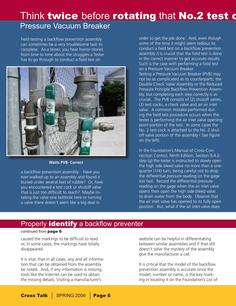
order to get the job done. And, even though some of the time it might seem tedious to conduct a field test on a backflow prevention assembly it is crucial that the field test is done in the correct manner to get accurate results. Such is the case with performing a field test on a Pressure Vacuum Breaker.Testing a Pressure Vacuum Breaker (PVB) may not be as complicated as its counterparts, the Double Check Valve Assembly or the Reduced Pressure Principle Backflow Prevention Assem-bly, but completing each step correctly is as crucial. The PVB consists of (2) shutoff valves, (2) test cocks, a check valve and an air inlet valve. A common mistake performed dur-ing the field test procedure occurs when the tester is performing the air inlet valve opening point portion of the test. In some cases the No. 2 test cock is attached to the No. 2 shut-off valve portion of the assembly ( See figure on the left).
In the Foundation’s Manual of Cross-Con-nection Control, Ninth Edition, Section 9.4.2. step (g) the tester is instructed to slowly open the high side bleed valve no more than a one-quarter (1/4) turn, being careful not to drop the differential pressure reading on the gage too fast. Record the differential pressure reading on the gage when the air inlet valve opens then open the high side bleed valve to drain water from the body. Observe that the air inlet valve has opened to its fully open position. But, what if the air inlet valve does
Watts PVB- Correct
caused the markings to be difficult to read or, in some cases, the markings have totally disappeared.
It is vital, that in all cases, any and all informa-tion that can be obtained from the assembly be noted. And, if any information is missing, tools like the Internet can be used to obtain the missing details. Visiting a manufacturer’s
website can be helpful in differentiating between similar assemblies and if that still doesn’t solve the mystery of the assembly give the manufacturer a call.
It is critical that the model of the backflow prevention assembly is accurate since the model, number or name, is the key mark-ing in locating it on the Foundation’s List of
Properly identify a backflow preventercontinued from page 6

Cross Talk SPRING 2006 Page 7
Think twice before rotating that No.2 test cock by rotating the No.2 shutoff valvePressure Vacuum Breaker
not open to its fully open position, then what might be the problem? The solution might have to do with a modification the installer made without much thought.
The PVB illustrated in the ninth edition of the Manual has the No. 2 test cock on the body of the PVB where it is easily accessible and convenient. But, in some cases the No. 2 test cock is located on the No. 2 shutoff valve por-tion of the assembly and is pointing down-ward. When the tester attaches the high side hose of the differential pressure gage to test cock No. 2 it may become cumbersome to reach underneath the assembly and gain ac-cess to the No. 2 test cock. The No. 2 shutoff valve may be rotated upward for easier access to the No. 2 test cock without giving it a sec-ond thought (See figure on the right).
However, rotating the No. 2 shutoff valve, allowing the tester more freedom when at-taching the high side hose, may not allow the air inlet valve to open fully. Rotating the No. 2 shutoff valve so that the No. 2. test cock is pointed upward prevents any water from being drained from the body of the PVB. The tester may open the high side bleed needle valve completely and yet the air inlet will not open to its fully open position.
Therefore, it is crucial that the No. 2 test cock be left in the original position and the high side bleed valve of the differential pressure
gage is opened to allow any water to drain out of the body of the assembly thus allowing the air inlet to open fully.
Simple modifications, like the one mentioned above, are what can cause an assembly to pass or fail in the field. And, sometimes try-ing to make the backflow prevention assem-bly more hassle-free isn’t always the best way to go. g
Watts PVB- Incorrect
Approved Backflow Prevention Assemblies. Members must remember that the model marking on the assembly must match exactly to what is listed on the List in order for the assembly to be an approved assembly. There-fore, it is essential to identify the backflow prevention assembly properly; whatever min-ute detail may be overlooked or assumed can cost an agency or business thousands of dol-
lars to replace an unapproved assembly. The model marking must match exactly, character for character, digit for digit, on both the List of Approved Assemblies and on the body of the backflow prevention assembly in order for it to be an approved USC assembly. g
Properly identify a backflow preventer

Foundation for Cross-ConnectionControl and Hydraulic Research
University of Southern CaliforniaKaprielian Hall 200Los Angeles, California 90089-2531
First ClassUS Postage PAID
University of Southern California
TrainingCourses
UpcomingEvents
Tester Course
Los Angeles, CA 9-13 October 2006
Los Angeles, CA 8-12 January 2007
Specialist Course
Santa Clara, CA 13-17 November 2006Los Angeles, CA 22-26 January 2007
Inland County Backflow Group SeminarSan Bernardino, CA 21 September 2006
ABPA Western RegionalBackflow Conference•Las Vegas, NV 9-10 October 2006
Western WashingtonAnnual Seminar•Tacoma, WA 18 October 2006
Contact Information
Phone: 866-545-6340
Fax: 213-740-8399
E-mail: [email protected]
Website: www.usc.edu/fccchr