µDim PIR Sensors User Manual
10
People | Innovations | Solutions µDim PIR Sensors User Manual
Transcript of µDim PIR Sensors User Manual
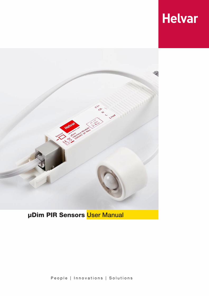
P e o p l e | I n n o v a t i o n s | S o l u t i o n s
µDim PIR Sensors User Manual
2
µDim
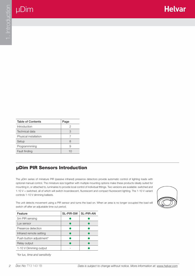
*for lux, time and sensitivity
1. In
trodu
ctio
n
Doc No: T13 143 1B Data is subject to change without notice. More information at: www.helvar.com
µDim PIR Sensors Introduction
The µDim series of miniature PIR (passive infrared) presence detectors provide automatic control of lighting loads with
optional manual control. The miniature size together with multiple mounting options make these products ideally suited for
mounting in, or attached to, luminaires to provide local control of individual fittings. Two versions are available: switched and
1-10 V + switched, all of which will switch incandescent, fluorescent and compact fluorescent lighting. The 1-10 V variant
controls 1-10 V dimming ballasts.
The unit detects movement using a PIR sensor and turns the load on. When an area is no longer occupied the load will
switch off after an adjustable time out period.
Feature SL-PIR-SW SL-PIR-AN
5m PIR sensing
Lux sensor
Presence detection
Infrared remote setting
Push button adjustment*
Relay output
1-10 V Dimming output -
Table of Contents Page
Introduction 2
Technical data 3
Physical installation 7
Setup 8
Programmming 9
Fault finding 10
3
µDim
2. T
echn
ical
Dat
a
Doc No: T13 143 1BData is subject to change without notice. More information at: www.helvar.com
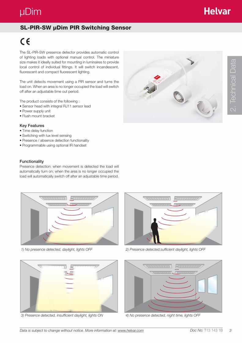
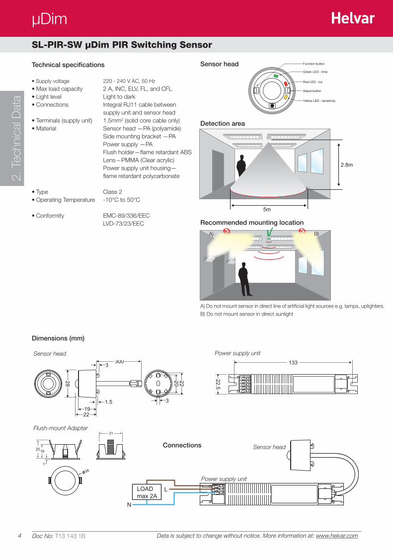
SL-PIR-SW µDim PIR Switching Sensor
The SL-PIR-SW presence detector provides automatic control of lighting loads with optional manual control. The miniature size makes it ideally suited for mounting in luminaires to provide local control of individual fittings. It will switch incandescent, fluorescent and compact fluorescent lighting.
The unit detects movement using a PIR sensor and turns the load on. When an area is no longer occupied the load will switch off after an adjustable time out period.
The product consists of the following :• Sensor head with integral RJ11 sensor lead• Power supply unit• Flush mount bracket Key Features• Time delay function• Switching with lux level sensing• Presence / absence detection functionality• Programmable using optional IR handset
FunctionalityPresence detection: when movement is detected the load will automatically turn on; when the area is no longer occupied the load will automatically switch off after an adjustable time period.
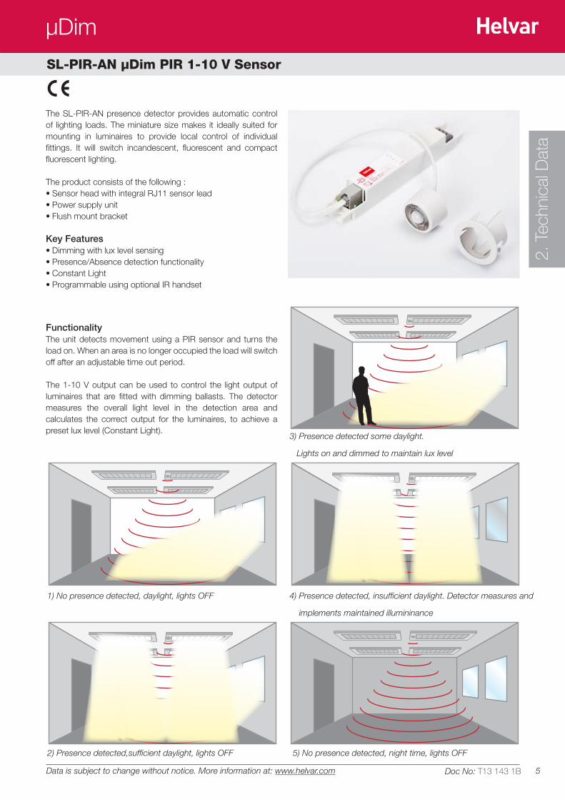
1) No presence detected, daylight, lights OFF
3) Presence detected, insufficient daylight, lights ON 4) No presence detected, night time, lights OFF
2) Presence detected,sufficient daylight, lights OFF
4
µDim2.
Tec
hnic
al D
ata
5m
2.8m
Recommended mounting location
Detection area
Connections
Dimensions (mm)
Sensor head
Flush-mount Adapter
Sensor head
Power supply unit
Power supply unit
Sensor head
28 20 22
19
3
31.5
22
300
22.5
20.5
133
145
LOAD max 2A
N
L
38
31
2519
1
A) Do not mount sensor in direct line of artificial light sources e.g. lamps, uplighters.
B) Do not mount sensor in direct sunlight
A) B)
Technical specifications
• Supply voltage 220 - 240 V AC, 50 Hz
• Max load capacity 2 A, INC, ELV, FL, and CFL• Light level Light to dark• Connections Integral RJ11 cable between
supply unit and sensor head• Terminals (supply unit) 1.5mm2 (solid core cable only)• Material Sensor head —PA (polyamide) Side mounting bracket —PA Power supply —PA Flush holder—flame retardant ABS Lens—PMMA (Clear acrylic) Power supply unit housing— flame retardant polycarbonate
• Type Class 2• Operating Temperature -10°C to 50°C
• Conformity EMC-89/336/EEC LVD-73/23/EEC
Green LED - time
Red LED - lux
Yellow LED - sensitivity
Adjust button
Function button
Doc No: T13 143 1B Data is subject to change without notice. More information at: www.helvar.com
SL-PIR-SW µDim PIR Switching Sensor
5
µDim
2. T
echn
ical
Dat
a
Doc No: T13 143 1BData is subject to change without notice. More information at: www.helvar.com
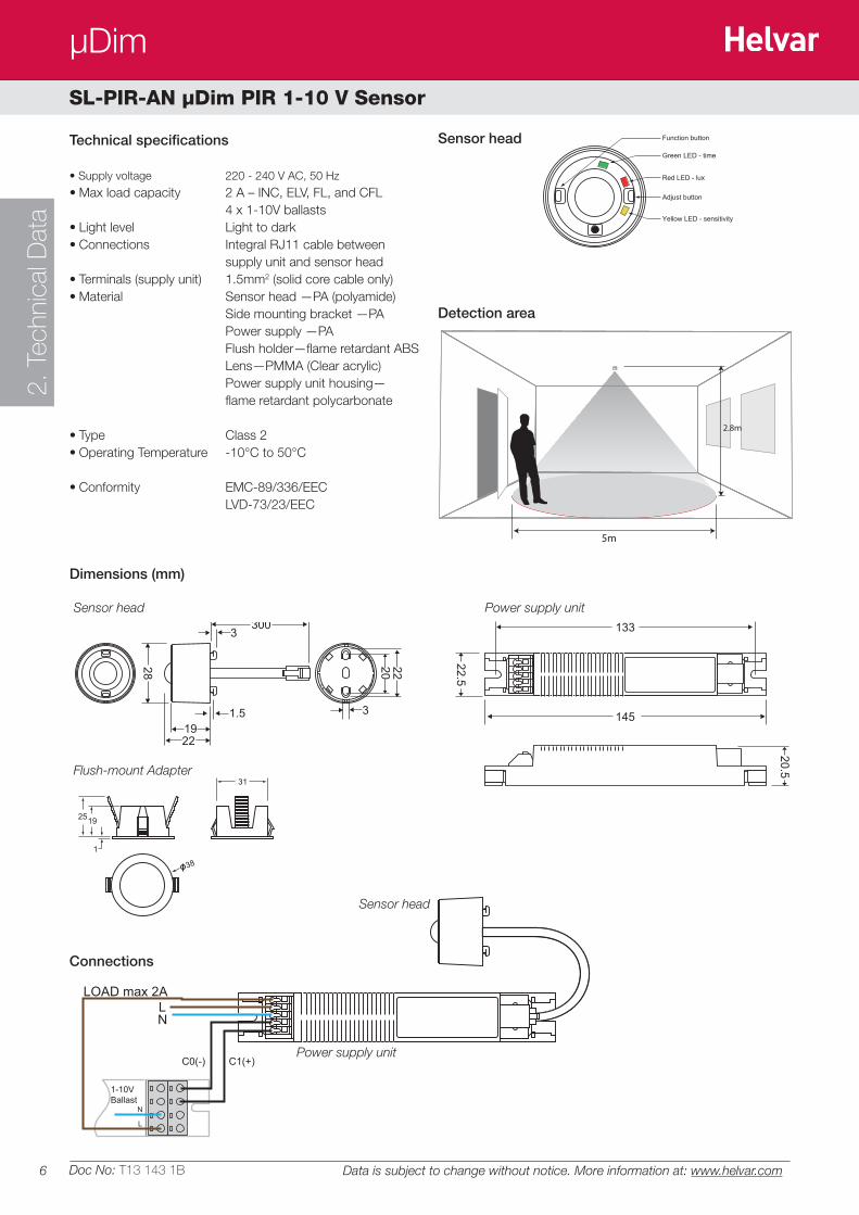
SL-PIR-AN µDim PIR 1-10 V Sensor
The SL-PIR-AN presence detector provides automatic control of lighting loads. The miniature size makes it ideally suited for mounting in luminaires to provide local control of individual fittings. It will switch incandescent, fluorescent and compact fluorescent lighting.
The product consists of the following :• Sensor head with integral RJ11 sensor lead• Power supply unit• Flush mount bracket Key Features• Dimming with lux level sensing• Presence/Absence detection functionality• Constant Light• Programmable using optional IR handset
FunctionalityThe unit detects movement using a PIR sensor and turns the load on. When an area is no longer occupied the load will switch off after an adjustable time out period.
The 1-10 V output can be used to control the light output of luminaires that are fitted with dimming ballasts. The detector measures the overall light level in the detection area and calculates the correct output for the luminaires, to achieve a preset lux level (Constant Light).
1) No presence detected, daylight, lights OFF 4) Presence detected, insufficient daylight. Detector measures and
implements maintained illumininance
3) Presence detected some daylight.
Lights on and dimmed to maintain lux level
5) No presence detected, night time, lights OFF2) Presence detected,sufficient daylight, lights OFF
6
µDim2.
Tec
hnic
al D
ata
Doc No: T13 143 1B Data is subject to change without notice. More information at: www.helvar.com
5m
2.8m
Detection area
Connections
Dimensions (mm)
Sensor head
Flush-mount Adapter
Sensor head
Power supply unit
Power supply unit
Sensor head
28 20 22
19
3
31.5
22
300
22.5
20.5
133
145
LOAD max 2A
NL
1-10V Ballast
C1(+)C0(-)
L
N
38
31
2519
1
Technical specifications
• Supply voltage 220 - 240 V AC, 50 Hz
• Max load capacity 2 A – INC, ELV, FL, and CFL 4 x 1-10V ballasts• Light level Light to dark• Connections Integral RJ11 cable between
supply unit and sensor head• Terminals (supply unit) 1.5mm2 (solid core cable only)• Material Sensor head —PA (polyamide) Side mounting bracket —PA Power supply —PA Flush holder—flame retardant ABS Lens—PMMA (Clear acrylic) Power supply unit housing— flame retardant polycarbonate
• Type Class 2• Operating Temperature -10°C to 50°C
• Conformity EMC-89/336/EEC LVD-73/23/EEC
Green LED - time
Red LED - lux
Yellow LED - sensitivity
Adjust button
Function button
SL-PIR-AN µDim PIR 1-10 V Sensor
7
µDim
3. In
stal
latio
n
Doc No: T13 143 1BData is subject to change without notice. More information at: www.helvar.com
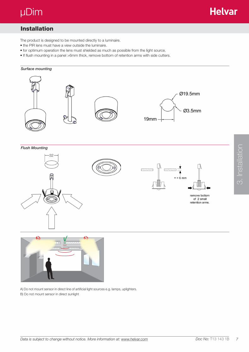
The product is designed to be mounted directly to a luminaire. • the PIR lens must have a view outside the luminaire.• for optimum operation the lens must shielded as much as possible from the light source.• If flush mounting in a panel >6mm thick, remove bottom of retention arms with side cutters.
Installation
Ø19.5mm
Ø3.5mm
19mm
5m
2.8m
A) Do not mount sensor in direct line of artificial light sources e.g. lamps, uplighters.
B) Do not mount sensor in direct sunlight
Surface mounting
Flush Mounting
32
8
µDim4.
Set
up
Doc No: T13 143 1B Data is subject to change without notice. More information at: www.helvar.com
Setup
Positioning• The detector should be sited so that the occupants of the room fall inside the detection pattern shown in section 7, at a
recommended ceiling height of 2.8m. Note that the lower the sensor is installed the smaller the detection range will be, subject to the parameters shown on the diagram.
• Avoid direct sunlight entering the sensor. • Do not site within 1m of forced air heating or ventilation. • Do not fix to a vibrating surface.
Settings
TimeSet the time period using the push button adjustment overleaf or the programming handset (see section 6). The factory default is 20 minutes.
LuxSL-PIR-SW—switch level on lux setting determines the ambient light level at which the lights turn on. This can be set using the push button
adjustment overleaf or the programming handset (see section 6). Setting to maximum ensures that lights always come on (this is also the
default setting).
SL-PIR-AN—switch level on described above is available using the programming handset only. The push button lux adjustment determines
the dimming output level and can be set using push button the programming handset light level and works as follows:
• During operation the output level varies very gradually. However when the level is changed the unit automatically enters setup mode: in this mode the output level varies rapidly. After the setup time the unit reverts to normal.
• When adjusting, allow the output level to settle by changing very gradually.• To disable the constant light function completely, set the level to maximum.
Programming handsetA host of other functions and settings are available using the programming handset—see section 5.
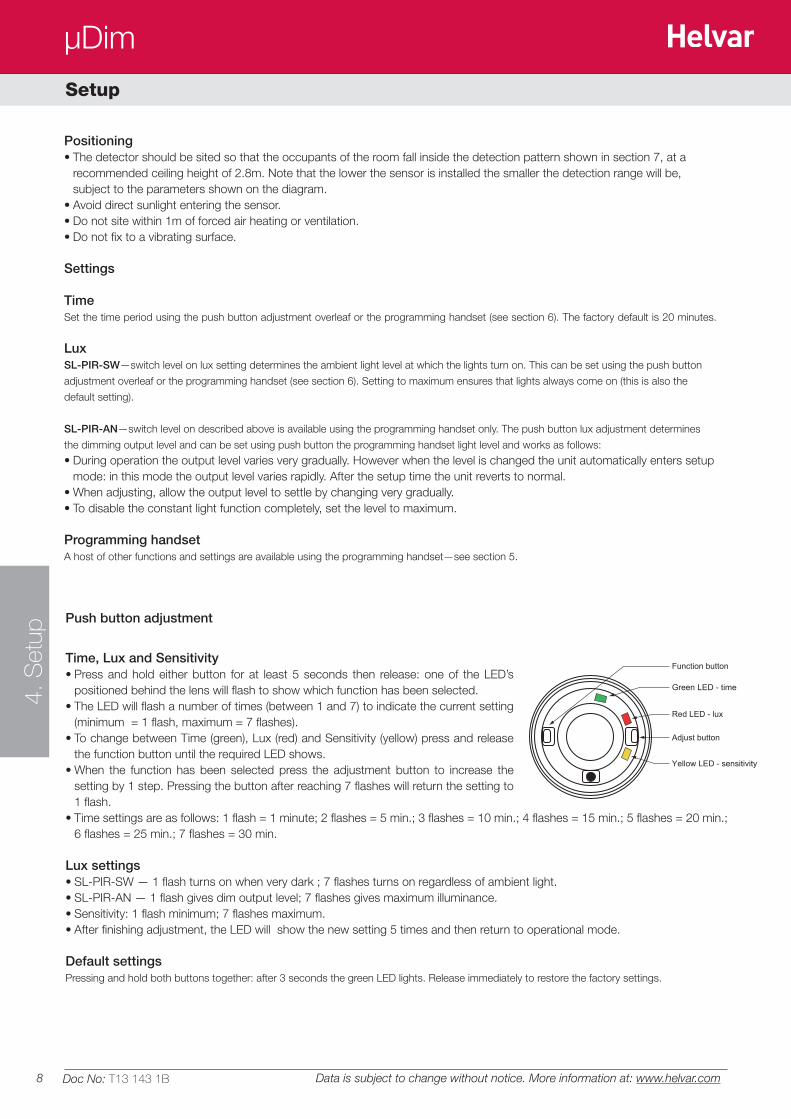
Push button adjustment
Time, Lux and Sensitivity• Press and hold either button for at least 5 seconds then release: one of the LED’s
positioned behind the lens will flash to show which function has been selected. • The LED will flash a number of times (between 1 and 7) to indicate the current setting
(minimum = 1 flash, maximum = 7 flashes). • To change between Time (green), Lux (red) and Sensitivity (yellow) press and release
the function button until the required LED shows. • When the function has been selected press the adjustment button to increase the
setting by 1 step. Pressing the button after reaching 7 flashes will return the setting to 1 flash.
• Time settings are as follows: 1 flash = 1 minute; 2 flashes = 5 min.; 3 flashes = 10 min.; 4 flashes = 15 min.; 5 flashes = 20 min.; 6 flashes = 25 min.; 7 flashes = 30 min.
Lux settings• SL-PIR-SW — 1 flash turns on when very dark ; 7 flashes turns on regardless of ambient light.• SL-PIR-AN — 1 flash gives dim output level; 7 flashes gives maximum illuminance.• Sensitivity: 1 flash minimum; 7 flashes maximum.• After finishing adjustment, the LED will show the new setting 5 times and then return to operational mode. Default settingsPressing and hold both buttons together: after 3 seconds the green LED lights. Release immediately to restore the factory settings.
Green LED - time
Red LED - lux
Yellow LED - sensitivity
Adjust button
Function button
9
µDim
5. P
rogr
amm
ing
Doc No: T13 143 1B
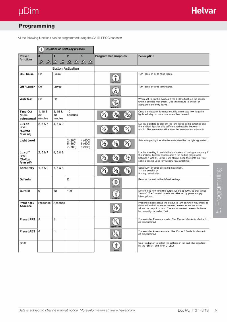
Preset functions
0 1 2 3 UHS5 Handset Graphics Description
Button Activation On / Raise On Raise Turn lights on or to raise lights.
Off / Lower Off Low er Turn lights off or to lower lights.
Walk test On Off When set to On this causes a red LED to flash on the sensor when it detects mov ement. Use this f eature to check f or adequate sensitiv ity lev els.
Time Out (Time adjustment)
1, 10 & 20 minutes
5, 15 & 30 minutes
10 seconds
Once the detector is turned on, this v alue sets how long the lights will stay on once mov ement has ceased.
Lux on level (Switch level on)
2, 5 & 7 4, 6 & 9 Lux lev el setting to prev ent the luminaires being switched on if the ambient light lev el is sufficient (adjustable between 1 and 9). The luminaires will alway s be switched on at lev el 9.
Light Level 2 (200) 5 (500) 7 (700)
4 (400) 6 (600) 9 (900)
Sets a target light lev el to be maintained by the lighting system.
Lux off level (Switch level off)
2, 5 & 7 4, 6 & 9 Lux lev el setting to switch the luminaires off during occupancy if the ambient light lev el goes abov e the setting (adjustable between 1 and 9). Lev el 9 will alway s keep the lights on. This setting can be used for “window row switching”.
Sensitivity 1, 5 & 9 3, 6 & 8 Sensitiv ity lev el f or detecting mov ement. 1 = low sensitiv ity 9 = high sensitiv ity
Defaults D Returns the unit to the def ault settings.
Burn-in 0 50 100 Determines how long the output will be at 100% so that lamps ‘burn-in’. The ’burn-in’ time is not aff ected by power supply interruptions.
Presence / Absence
Presence Absence Presence mode allows the output to turn on when mov ement is detected and off when mov ement ceases. Absence mode allows the output to turn off when mov ement ceases, but must be manually turned on f irst.
Preset PRS A B 2 presets f or Presence mode. See Product Guide for device to be programmed
Preset ABS A B 2 presets f or Absence mode. See Product Guide for device to be programmed
Shift Use this button to select the settings in red and blue signif ied by the ‘Shif t 1’ and ‘Shift 2’ LEDs
Number of Shift key presses
SHIFT 1 SHIFT 2 SHIFT 1 SHIFT 2 SHIFT 1 SHIFT 2 SHIFT 1 SHIFT 2
Programmer Graphics
All the following functions can be programmed using the SA-IR-PROG handset:
Data is subject to change without notice. More information at: www.helvar.com
Programming
10
µDim
Doc No: T13 143 1B
LOAD DOES NOT COME ON
Check to see if the live supply to the circuit is good. Strap across the L
and LIVE OUT (where used) terminal to turn the load on.
If the supply and wiring are good, check the LUX level setting. Increase
the LUX level setting to allow the controller to turn on at higher ambient
natural light level.
If the detection range is smaller than expected, check the diagram
above. Rotating the sensor slightly may improve the range.
LIGHTS DO NOT GO OFF
Ensure that the area is left unoccupied for longer than the selected timer
setting.
Make sure that the sensor is not adjacent to circulating air, heaters or
lamps.
If the unit “false triggers” reduce the sensitivity using the sensitivity
settings (see section 5 and 6).
Data is subject to change without notice. More information at: www.helvar.com
Fault finding
Part numbers
Helvar Oy AbYrittäjäntie 23, P.O.Box 100
FI-03601 KarkkilaFinland
www.helvar.com
FI: +358 9 56 54 1UK: +44 1322 222 211SE: +46 8 545 239 70FR: +33 1 3418 1281
IT: +39 02 55 30 10 33DE: +49 6104 78075
RU: +7 (495) 728 82 91HU: +36 1 2393 136
CN: + 86 512 6763 3078
Product: µDim PIR sensors User ManualDoc No. T13 143 1B
Issue 2
SL-PIR-SW Miniature PIR with switched (relay) output
SL-PIR-AN Miniature PIR with 1-10V Analogue and switched (relay) output
Accessories
SA-IR-PROG IR programming handset
IMPORTANT NOTICE!
This device should be installed by a qualified
electrician in accordance with the latest
edition of the IEE wiring regulations.