DILM95(230V50HZ,240V60HZ) Article No.: 239480...
12
Type: DILM95(230V50HZ,240V60HZ) Article No.: 239480 Sales text Contactor,45kW/400V,AC operated Ordering information Connection technique Screw terminals Description 3 pole Description Springloaded terminals on the auxiliary and control circuit terminals Rated operational current AC-3 380 V 400 V I e A 95 Max. rating for three-phase motors, 50 – 60 Hz AC-3 220 V 230 V P kW 30 AC-3 380 V 400 V P kW 45 AC-3 660 V 690 V P kW 75 AC-4 220 V 230 V P kW 16 AC-4 380 V 400 V P kW 26 AC-4 660 V 690 V P kW 35 Conventional free air thermal current I th = I e AC-1 at 60 °C Open I th = I e A 110 Contacts Can be combined with auxiliary contact DILM150-XHI(V).. DILM1000-XHI(V).. 1
-
Upload
truongthuan -
Category
Documents
-
view
234 -
download
0
Transcript of DILM95(230V50HZ,240V60HZ) Article No.: 239480...

Type: DILM95(230V50HZ,240V60HZ)Article No.: 239480Sales text Contactor,45kW/400V,AC operated
Ordering information
Connection technique Screw terminals
Description 3 pole
DescriptionSpringloaded terminals on theauxiliary and control circuitterminals
Rated operational current
AC−3 380 V 400 V Ie A 95
Max. rating for three−phase motors, 50– 60 Hz
AC−3 220 V 230 V P kW 30
AC−3 380 V 400 V P kW 45
AC−3 660 V 690 V P kW 75
AC−4 220 V 230 V P kW 16
AC−4 380 V 400 V P kW 26
AC−4 660 V 690 V P kW 35
Conventional free air thermal current I th= I e AC−1 at 60 °C
Open Ith = Ie A 110
Contacts
Can be combined with auxiliary contact DILM150−XHI(V)..DILM1000−XHI(V)..
1

Actuating voltage 230 V 50 Hz, 240 V 60 Hz
Contact sequence
Notes concerning the product group
Accessories1 Overload relay 2784422 Suppressor 2811993 Auxiliary contact module 277376Further actuating voltages 277379Accessories 281227
The DC operated contactors haveintegral suppressor circuits (DILM7 −DILM15: Varistor).
Contactors DILM115, DILM150 andDILM170 have a built−in suppressorcircuit.
Mirror contact for DILM7−01 toDILM32−01
Contactor contact according to EN50012
General
Standards IEC/EN 60947, VDE 0660,UL, CSA
Lifespan, mechanical
2
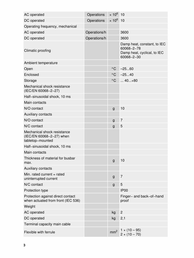
AC operated Operations × 106 10
DC operated Operations × 106 10
Operating frequency, mechanical
AC operated Operations/h 3600
DC operated Operations/h 3600
Climatic proofing
Damp heat, constant, to IEC60068−2−78Damp heat, cyclical, to IEC60068−2−30
Ambient temperature
Open °C –25...60
Enclosed °C –25...40
Storage °C ... 40...+80
Mechanical shock resistance(IEC/EN 60068−2−27)
Half−sinusoidal shock, 10 ms
Main contacts
N/O contact g 10
Auxiliary contacts
N/O contact g 7
N/C contact g 5
Mechanical shock resistance(IEC/EN 60068−2−27) whentabletop−mounted
Half−sinusoidal shock, 10 ms
Main contacts
Thickness of material for busbarmax. g 10
Auxiliary contacts
Min. rated current = rateduninterrupted current g 7
N/C contact g 5
Protection type IP00
Protection against direct contactwhen actuated from front (IEC 536)
Finger− and back−of−handproof
Weight
AC operated kg 2
DC operated kg 2,1
Terminal capacity main cable
Flexible with ferrule mm2 1 × (10 – 95)2 × (10 – 70)
3

Stranded mm2 1 × (16 – 95)2 × (16 – 70)
Solid or stranded AWG 8...3/0
Flat conductor
Number ofsegments ×
width ×thickness
mm 2 × (6 × 16 × 0.8)
Main cable connection screw/bolt M10
Tightening torque Nm 14
Terminal capacity control circuitcables
Solid mm2 1 × (0.75 – 4)2 × (0.75 – 4)
Flexible with ferrule mm2 1 × (0.75 – 2.5)2 × (0.75 – 2.5)
Solid or stranded AWG 18 – 14
Control circuit cable connectionscrew/bolt M3.5
Tightening torque Nm 1.2
Tool
Main cable
Hexagon socket−head spanner SW mm 5
Control circuit cables
Pozidriv screwdriver Size 2
Standard screwdriver mm 0.8 × 5.51 × 6
Terminal capacity control circuitcables
Solid mm2 1 × (0.75 – 2.5)2 × (0.75 – 2.5)
Flexible mm2 1 × (0.75 – 2.5)2 × (0.75 – 2.5)
Flexible with ferrule mm2 1 × (0.75 – 1.5)2 × (0.75 – 1.5)
Solid or stranded AWG 18 – 14
Tool
Stripping length mm 10
Screwdriver blade width mm 3,5
Main conducting paths
Rated impulse withstand voltage Uimp V AC 8000
Overvoltage category/pollutiondegree III/3
4

Rated insulation voltage Ui V AC 1000
Rated operational voltage Ue V AC 1000
Safe isolation to VDE 0106 Part 101and Part 101/A1
between coil and contacts V AC 690
between the contacts V AC 690
Making capacity (p.f. to IEC/EN60947)
Up to 690 V A 1330
Breaking capacity
220/230 V A 950
380/400 V A 950
500 V A 950
660/690 V A 800
Short−circuit rating
Short−circuit protection maximumfuse
Type “2” coordination
400 V gG/gL 500 V A 160
690 V gG/gL 690 V A 160
Type “1” coordination
400 V gG/gL 500 V A 250
690 V gG/gL 690 V A 200
AC
AC−1 duty
conv. therm. current 3 pole 50 – 60Hz
open
at 40 °C Ith A 130
at 50 °C Ith A 125
at 55 °C Ith A 115
at 60 °C Ith A 110
enclosed Ith A 100
Conventional free air thermal current,1 pole
open Ith A 275
enclosed Ith A 250
AC−3 duty
Rated operational current AC−3open, 50 – 60 Hz, 3 pole
5

220/230 V Ie A 95
240 V Ie A 95
380/400 V Ie A 95
415 V Ie A 95
440V Ie A 95
500 V Ie A 95
660/690 V Ie A 80
Motor rating
220/230 V P kW 30
240V P kW 4
380/400 V P kW 45
415 V P kW 57
440 V P kW 60
500 V P kW 70
660/690 V P kW 75
AC−4 duty
Rated operational current AC−4open, 50 – 60 Hz, 3 pole
220/230 V Ie A 50
240 V Ie A 50
380/400 V Ie A 50
415 V Ie A 50
440 V Ie A 50
500 V Ie A 50
660/690 V Ie A 37
Motor rating
220/230 V P kW 16
240 V P kW 17
380/400 V P kW 26
415 V P kW 30
440 V P kW 32
500 V P kW 36
660/690 V P kW 35
DC
of three−phase capacitors open
DC−1 operation
60 V Ie A 110
110 V Ie A 110
220 V Ie A 70
6

440 V Ie A 4,5
DC−3 operation
60 V Ie A 110
110 V Ie A 110
220 V Ie A 35
440 V Ie A 1
DC−5 operation
60 V Ie A 110
110 V Ie A 110
220 V Ie A 35
440 V Ie A 1
Current heat loss (3 pole)
Current heat loss at Ith W 18,2
Current heat loss at Ie to AC−3/400 V W 13,5
Impedance per pole m 0,5
Magnet systems
Voltage tolerance
AC operated Pick−up × Uc 0,8...1,1
Drop−out voltage AC operated Drop−out × Uc 0,3...0,6
DC operated Pick−up × Uc 0,7...1,2
DC operated Drop−out × Uc 0,15...0,6
Power consumption of the coil in acold state and 1.0 × Uc
50 Hz Pick−up VA 310
50 Hz Sealing VA 26
50 Hz Sealing W 5,8
60 Hz Pick−up VA 345
60 Hz Sealing VA 30
60 Hz Sealing W 7,1
50/60 Hz Pick−up VA 372328
50/60 Hz Sealing VA 37,122,6
50/60 Hz Sealing W 7,56,1
DC operated Pick−up W 90
DC operated Sealing W 1.3
Duty factor % DF 100
Switching times at 100 % Uc(approximate values)
7

Main contacts
AC operated
Closing delay ms 14...20
Opening delay ms 9...14
DC operated
Closing delay ms 45
Opening delay ms 34
Arcing time ms 15
Permissible residual current withactuation of A1 – A2 by theelectronics (with 0 signal).
mA 1
Lifespan, mechanical; Coil 50/60 Hz at 50 HzMechanical lifespan at 50 Hzapprox. 30% lower thanunder “General”
Electromagnetic compatibility (EMC)
Emitted interference to EN 60947−1
Interference immunity to EN 60947−1
Notes
Notes
The following applies tomagnet systems, voltagetolerance, pickup voltageDC−operated DILM17 –DILM32:RDC 24 (Umin 24 VDC/Umax 27 V DC)RDC 60 (Umin 48 VDC/Umax 60 V DC)RDC 130 (Umin 110 VDC/Umax 130 V DC)RDC 240 (Umin 200 VDC/Umax 240 V DC)Example:Uc = 0.7 x Umin − 1.2 xUmaxUc = 0.7 x 24 V − 1.2 x 27 VDCWith voltage tolerance andDC operated powerconsumption the followingapplies: At least smootheddouble−pulse bridgerectification or a three−phasecurrent rectifier is necessary
Mounting position, AC− and DC operated
8

Dimensions
Dimensions
9

distance at side to earthed parts: 10 mm
Basic unit with auxiliary contact module
Characteristic curve
10
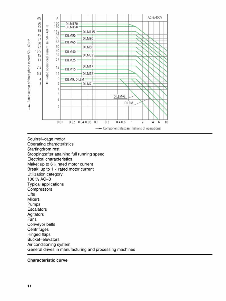
Squirrel−cage motorOperating characteristicsStarting:from restStopping:after attaining full running speedElectrical characteristicsMake: up to 6 × rated motor currentBreak: up to 1 × rated motor currentUtilization category100 % AC−3Typical applicationsCompressorsLiftsMixersPumpsEscalatorsAgitatorsFansConveyor beltsCentrifugesHinged flapsBucket−elevatorsAir conditioning systemGeneral drives in manufacturing and processing machines
Characteristic curve
11

Extreme switching dutySquirrel−cage motorOperating characteristicsInching, plugging, reversingElectrical characteristicsMake: up to 6 × rated motor currentBreak: up to 6 × rated motor currentUtilization category100 % AC−4Typical applicationsPrinting pressesWire−drawing machinesCentrifugesSpecial drives for manufacturing and processing machines
Moeller GmbH, Hein−Moeller−Str. 7−11, D−53115 BonnE−Mail: [email protected], Internet: www.moeller.net, http://catalog.moeller.netCopyright 2006 by Moeller GmbH. HPL−C2007G V2.1
12