Digital Lighting Management - WattStopper
36
800.879-8585 www.wattstopper.com ©2009-2010 WattStopper Table of Contents D i g i t a l L i g h t i n g M a n a g e m e n t This guide shows you how to install, configure and use a WattStopper Digital Lighting Management (DLM) system. It complements the instructions supplied with each DLM product. Carefully read all product instructions. This guide assumes a basic knowledge of good wiring practices. All wiring must comply with applicable electrical and safety codes. All electrical installation work should be carried out by an experienced electrician. DLM System Installation Guide » SYSTEM OVERVIEW Digital Lighting Management ......................2 Wiring ...........................................................2 Setup and Configuration..............................2 Local Network Layout Examples ................3 » ROOM CONTROLLERS LMRC-101 and LMRC-102 ..........................4 LMPL-101 Plug Load Controller .................5 » SWITCHES LMSW-101, 102, 103, 104 & 108 .................6 » OCCUPANCY SENSORS Sensor Operation Overview .........................8 Occupancy Sensor Specifications ...............9 Corner Mount Instructions .........................9 Ceiling Mount Instructions .........................9 LMDX-100 Digital Dual Technology Corner Mount Sensor............................. 10 LMPX-100 Digital PIR Corner Mount Sensor............................. 11 LMDC-100 Digital Dual Technology Ceiling Mount Sensor ............................. 13 LMPC-100 Series Digital PIR Ceiling Mount Sensor ............................. 14 LMUC-100-2 Digital Ultrasonic Ceiling Mount Sensor ............................. 15 » SENSOR PROGRAMMING LCD Display Overview - Abbreviations...... 16 Codes in the Display .................................. 18 Push n’ Learn™ ......................................... 19 » RESET OPTIONS Device & System resets ............................ 21 » WIRELESS INFRARED COMMUNICATION Infrared Communication Overview ........... 23 » CONFIGURATION TOOL LMCT-100 Digital IR Configuration Tool ...24 » CEILING MOUNT IR TRANSCEIVER LMIR-100 Digital Infrared Receiver .......... 25 » HANDHELD REMOTE LMRH-102 Digital IR Handheld Remote ...26 » DAYLIGHT SENSORS LMLS-105 Daylight Sensor - Closed Loop ON/OFF ........................... 28 LMLS-305 Daylight Sensor - Closed Loop Dimming ......................... 30 » EXTERNAL SYSTEM INTERFACES Interface Modules to 3rd party systems ...32 LMRL-100 Isolated Relay Interface ......... 33 LMIO-101 Digital Input/output Interface...34 REFERENCES LMRJ Cable Specification.......................... 36 Safety ......................................................... 36 Patents ....................................................... 36 Warranty Information ................................ 36
Transcript of Digital Lighting Management - WattStopper

800.879-8585
www.wattstopper.com
©2009-2010 WattStopper
Table of Contents
D i g i t a l L i g h t i n g M a n a g e m e n t
This guide shows you how to install, configure and use a WattStopper Digital Lighting Management (DLM) system. It complements the instructions supplied with each DLM product. Carefully read all product instructions. This guide assumes a basic knowledge of good wiring practices. All wiring must comply with applicable electrical and safety codes. All electrical installation work should be carried out by an experienced electrician.
DLM System Installation Guide
» SYSTEM OVERVIEW Digital Lighting Management ......................2Wiring ...........................................................2Setup and Configuration ..............................2Local Network Layout Examples ................3
» ROOM CONTROLLERSLMRC-101 and LMRC-102 ..........................4LMPL-101 Plug Load Controller .................5
» SWITCHESLMSW-101, 102, 103, 104 & 108 .................6
» OCCUPANCY SENSORSSensor Operation Overview .........................8Occupancy Sensor Specifications ...............9Corner Mount Instructions .........................9Ceiling Mount Instructions .........................9LMDX-100 Digital Dual Technology
Corner Mount Sensor .............................10LMPX-100 Digital PIR
Corner Mount Sensor .............................11LMDC-100 Digital Dual Technology
Ceiling Mount Sensor .............................13LMPC-100 Series Digital PIR
Ceiling Mount Sensor .............................14LMUC-100-2 Digital Ultrasonic
Ceiling Mount Sensor .............................15
» SENSOR PROGRAMMINGLCD Display Overview - Abbreviations......16Codes in the Display ..................................18Push n’ Learn™ .........................................19
» RESET OPTIONSDevice & System resets ............................21
» WIRELESS INFRARED COMMUNICATIONInfrared Communication Overview ...........23
» CONFIGURATION TOOLLMCT-100 Digital IR Configuration Tool ...24
» CEILING MOUNT IR TRANSCEIVERLMIR-100 Digital Infrared Receiver ..........25
» HANDHELD REMOTELMRH-102 Digital IR Handheld Remote ...26
» DAYLIGHT SENSORSLMLS-105 Daylight Sensor
- Closed Loop ON/OFF ...........................28LMLS-305 Daylight Sensor
- Closed Loop Dimming .........................30
» EXTERNAL SYSTEM INTERFACESInterface Modules to 3rd party systems ...32LMRL-100 Isolated Relay Interface .........33LMIO-101 Digital Input/output Interface...34
REFERENCESLMRJ Cable Specification ..........................36Safety .........................................................36Patents .......................................................36Warranty Information ................................36

2
» System Overview
The DLM system integrates load control with occupancy sensors, daylight sensors, switches, and other devices to provide simple code compliant solutions for lighting. It is a powerful, flexible, scalable, easy to install lighting control system designed to provide maximum energy savings. It uses plug-in low voltage connections to create a DLM Local Network in any room, office, commercial space or restaurant. Room Controllers serve as the foundation of any DLM system. The room controllers manage communication between DLM devices, control line voltage outputs to lighting loads and provide low voltage power to all connected DLM devices.
WIRING
Control (Low Voltage Class 2) Wiring
All DLM devices are connected to the room controller(s) using WattStopper LMRJx cables through a free-topology DLM Local Network. Therefore, any DLM device can connect to any other DLM device that has an open RJ-45 receptacle. The illustrations in this guide show just a few examples of how the DLM devices can be connected to create the DLM Local Network.
The LMRJ cables are sold in various lengths. Review the distances between devices to ensure you have the proper cable lengths for your project. Avoid using splitters and couplers whenever possible. Most DLM devices have two or three RJ-45 receptacles. Daylighting and corner mount occupancy sensors have only a single RJ-45 plug, so a cable splitter or coupler (included) is required to connect them to the DLM Local Network.
The DLM Local Network can support up to 1,000 feet of LMRJ cable, up to 24 devices, including up to a total of four LMRC-10x room controllers and/or LMPL-101 plug load controllers. The maximum cable between devices on the DLM Local network is 300’. 150’ of cable is allowed per device; a two device network is allowed 300’, 3 devices 450’ etc., up to 1,000’ maximum.
DIGITAL LIGHTING MANAGEMENT
1. Don’t leave any cable end unplugged.
2. Don’t loop a cable back into the same device.
3. Don’t make a complete circuit with the LMRJ.
LMRJ cable trouble prevention
Line and Load (High Voltage) Wiring
All line voltage flying leads on room and plug load controllers are #12 AWG. Wire connections shall be suitable for the wire gauge (lead and building wiring) employed. Installation shall be in accordance with all applicable regulations, wiring practices, and NEC codes.
SETUP AND CONFIGURATION
Plug n’ Go™ (PnG): Default Operation Upon initial power up, the DLM system automatically identifies the devices on the Local Network then enters the WattStopper patented Plug n’ Go™ configuration to allow basic operation of all DLM devices. In most applications the relationship between quantity of loads, switches and occupancy sensors will not require any adjustments.
PnG sets up the most energy efficient control strategy. For example, if at least one switch and one occupancy sensor are on the DLM Local Network to control two loads, the system defaults to auto ON 50%. Load 1 turns ON automatically with occupancy and load 2 must be turned ON manually from the switch. Both loads turn OFF when the sensor time delay expires. If a two-button switch is used, PnG operation is the same except that the loads are independently controlled from separate buttons.
PnG operation depends on the types of devices installed. A description of system PnG operation for each device is included in the device section.
Push n’ Learn™ (PnL): Custom OperationA configuration (Config) button on most DLM devices allows easy access to the WattStopper patented Push n’ Learn™ technology to modify system operation. Functionality of the Config button is standardized throughout the DLM product line, as is the operation of the Config LED indicators. In addition, the Configuration Tool provides remote infrared access to PnL and sensor adjustment parameters.

DLM System Installation Guide 3
System Overview
Three load DLM Local Network configuration example
One load DLM Local Network configuration example
Switch
Ceiling MountSensor
Load
1
LineVoltage
J-Box
LMRC 101Room
Controller
Local NetworkLMRJ Cables
Switch Ceiling MountSensor
Load
3
LineVoltage
J-Box
LMRC-101Room Controller
LineVoltage
LMRC-102Room Controller
J-Box
DaylightSensor
Switch Switch
Corner MountSensor
Ceiling MountSensor
Loads
2
1
LineVoltage
LMRC-102Room
Controller
J-Box
DaylightSensor
Switch Switch
Corner MountSensor
Corner MountSensor
Loads
2
1
LineVoltage
LMRC-102Room
Controller
J-BoxLoads
4
3
Ceiling MountSensor
Switch
Four load DLM Local Network configuration example
Two load DLM Local Network configuration example
LineVoltage
LMRC-102Room
Controller
J-Box
DaylightSensor
Switch
Switch
Corner MountSensor
Loads
2
1
Ceiling MountSensor
Manual ON Auto OFF and Manual OFF
PnG Operation
Auto and Manual ON Daylighting control Auto OFF and Manual OFF
Manual ON Auto OFF and Manual OFF
DIGITAL LIGHTING MANAGEMENT LOCAL NETWORK LAYOUT EXAMPLES
3-device network, 150’ for each device = 450’ max for cable
Max cable between any two devices is 300’
6-device network, 150’ for each device = 900’ max for cable
Max cable between any two devices is 300’
9-device network, but DLM Local Network limit = 1000’ max for cable
Max cable between any two devices is 300’
DLM Local Network limit = 1000’ max for cable
Max cable between any two devices is 300’
Max 24 devices, including
up to four LMRC-100 series controllers.

4
» Room Controllers
LMRC-101 AND LMRC-102 ROOM CONTROLLERS
LMRC-101/102 Connectivity
The LMRC-101 and LMRC-102 are powered by 120/230/277VAC, 50/60Hz. Up to four room controllers can be interconnected on the DLM Local Network. The LMRC-101 has one load controlling relay and the LMRC-102 has two load controlling relays (Load A and Load B). Connect only one 120VAC or one 277VAC circuit to a room controller. If there are mixed voltages in the room, install at least two room controllers.
Load Control Arbitration
To take full advantage of automatic PnG configuration, review these simple rules about load control arbitration.
After the room controllers are connected to the DLM Local Network and powered up they automatically negotiate to determine which controller becomes the Master and to assign the load numbers for each relay on the DLM Local Network.
The Master is the controller with the most load relays and the highest serial number.
Controllers with more than one relay are labeled with sequential letters to identify loads. For example, the LMRC-102 has loads A and B, which, if it is the Master, would be Load 1 and Load 2 on the DLM Local Network. The LMRC-102 with the next highest serial number on the DLM Local Network would have Load 3 connected to its A load wire and Load 4 on its B load wire, and so forth.
Low Voltage Wiring
Each room controller provides up to 150mA @ 24VDC to class 2 devices (sensors, switches, etc.) on the DLM Local Network via LMRJ-x Cat 5e cables. The available current is cumulative, meaning that each room controller contributes to the power available on the DLM Local Network. A DLM Local Network, fully loaded with four room controllers carries 600mA.
To access the LMRJ receptacles, lift the “clamshell” cover on the controller. Plug the cables into the receptacles then secure them under the strain relief hooks. Cover any unused receptacle with the black rubber plug provided.
Mounting and Placement
Room controllers can mount external to a junction box in the plenum space, or they can mount inside a 4” x 4” junction box. Each room controller has a threaded nipple that fits into a ½” knockout.
Power Up Functionality
On power up, the DLM system automatically uses the PnG configuration appropriate to the number of loads and types of devices on the DLM Local Network. In common applications, the relationship between quantity of loads, switches and occupancy sensors won’t require any adjustments.
To customize operation of the system see PUSH n’ LEARN.
J-Box
Load�
�Line
�Line
J-Box
Load�
0461373638
0341373638
Serial Number
RoomController
LoadControl
LMRC-1023
4
0461373679
Master
0341373638
LMRC-1021
2
0458356133 0341373638
LMRC-101
5
0427350315 0341373638
LMPL-101
A
B
A
A
A
B
6

DLM System Installation Guide 5
LMRC-101 AND LMRC-102 continued
LED Indicators
The room controllers contain two different colored LEDs. Blue status LEDs indicate the relay status; they are solid ON when the relay is closed and OFF when the relay is open.
A red LED blinks about once every three seconds when the room controller is in standard operating mode. When the room controller enters Push n’ Learn mode, the red LED blinks twice each second.
Load ON/OFF Button
Pressing the Load ON/OFF button toggles the state of the associated relay to turn the load ON or OFF. It temporarily overrides automatic control signals from an occupancy sensor or a daylight sensor. The Load ON/OFF button is used primarily during installation to verify proper operation of the relay.
Specifications.
Input Voltage: LMRC-101 & LMRC-102 . . . . . . . . . . . . . . . . . . . . . . . . . . . .120VAC or 230VAC or 277VAC, 50/60Hz LMPL-101 . . . . . . . . . . . . . . . . . . . . . . . . . . . . . . . . . . . . . . . . . . . . . . . . . . . . . . . . . . 120VAC, 50/60HzLoad Ratings: Incandescent. . . . . . . . . . . . . . . . . . . . . . . . . . . . . . . . . . . . . . . . . . . . . . . . . . . . . . . . . . . 20A @ 120VAC Ballast . . . . . . . . . . . . . . . . . . . . . . . . . . . . . . . . . . . . . . . . . . . . . . . . . . . . . . . . . . . . 20A @ 120/277VAC Motor . . . . . . . . . . . . . . . . . . . . . . . . . . . . . . . . . . . . . . . . . . . . . . . . . . . . . . . . . . . . . 1Hp @ 120/240VACOutput . . . . . . . . . . . . . . . . . . . . . . . . . . . . . . . . . . . . . . . . . . . . . . . . . . . . . . . . . . . . . . . . 150mA @ 24VDCEnvironment . . . . . . . . . . . . . . . . . . . . . . . . . . . . . . . . . . . . . . . . . . For Indoor Use Only, Plenum Rated Operating Temperature. . . . . . . . . . . . . . . . . . . . . . . . . . . . . . . . . . . . . . . . . 32° to 104°F (0° to 40°C) Storage Temperature . . . . . . . . . . . . . . . . . . . . . . . . . . . . . . . . . . . . . . . . . 23° to 176°F (-5° to 80°C) Relative Humidity . . . . . . . . . . . . . . . . . . . . . . . . . . . . . . . . . . . . . . . . . . . . 5 to 95% (non condensing)
Each LMRC-100 series room controller (or LMPL-101) adds 150mA of power to the DLM Local Network: 1 LMRC-100 series = 150mA, 2 = 300mA, 3 = 450mA, 4 = 600mA (maximum 4).
When installing multiple controllers, it is best practice to spread them throughout the DLM Local Network with devices connected to each controller, rather than all the controllers at one end with LMRC cable connections only to other controllers.
LMPL-101 PLUG LOAD CONTROLLER
With the exception of the features described below, the LMPL-101 has the same mechanical form and features as the LMRC-101.
LMPL-101 Connectivity
The LMPL-101 is powered by 120VAC, 50/60Hz. The LMPL-101 counts as one of the four controllers that can be interconnected on the DLM Local Network. The LMPL-101 has one load controlling relay intended for connection to an electrical wall outlet circuit for plug load control.
Power Up Functionality
Upon initial power up, the plug load circuit connected to the LMPL-101 is automatically controlled by all occupancy sensors on the DLM Local Network; it is not bound to any switch button. After the last occupancy sensor’s time delay expires, the LMPL-101 shuts OFF the plug load circuit.
Room Controllers
Con�guration ButtonCon�guration: Red LED
Load B On/Off Button (LMRC-102 Only)
Load B Status: Blue LED (LMRC-102 Only)
Load A On/Off ButtonLoad A Status: Blue LED
6
» Switches
LMSW-101, 102, 103, 104 & 108
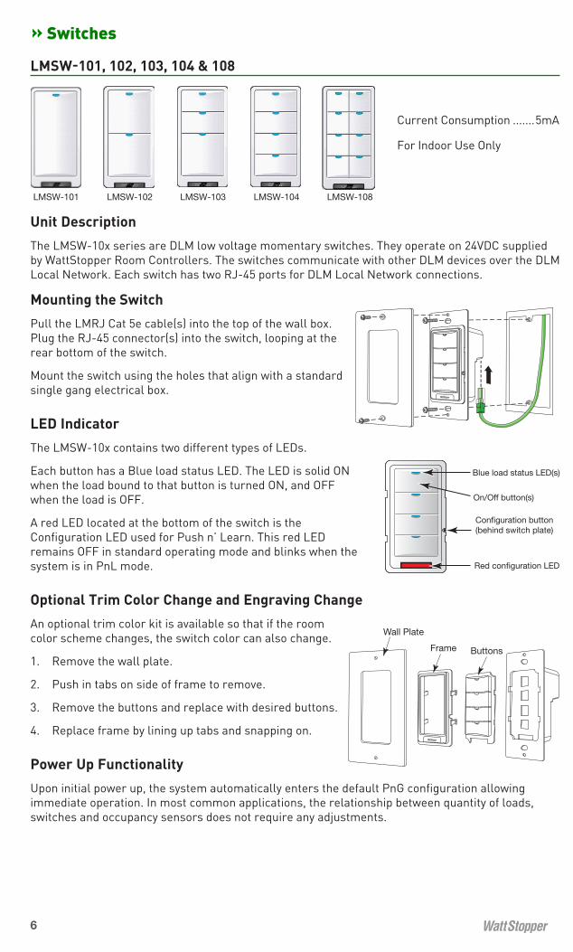
Unit Description
The LMSW-10x series are DLM low voltage momentary switches. They operate on 24VDC supplied by WattStopper Room Controllers. The switches communicate with other DLM devices over the DLM Local Network. Each switch has two RJ-45 ports for DLM Local Network connections.
Mounting the Switch
Pull the LMRJ Cat 5e cable(s) into the top of the wall box. Plug the RJ-45 connector(s) into the switch, looping at the rear bottom of the switch.
Mount the switch using the holes that align with a standard single gang electrical box.
LED Indicator
The LMSW-10x contains two different types of LEDs.
Each button has a Blue load status LED. The LED is solid ON when the load bound to that button is turned ON, and OFF when the load is OFF.
A red LED located at the bottom of the switch is the Configuration LED used for Push n’ Learn. This red LED remains OFF in standard operating mode and blinks when the system is in PnL mode.
Optional Trim Color Change and Engraving Change
An optional trim color kit is available so that if the room color scheme changes, the switch color can also change.
1. Remove the wall plate.
2. Push in tabs on side of frame to remove.
3. Remove the buttons and replace with desired buttons.
4. Replace frame by lining up tabs and snapping on.
Power Up Functionality
Upon initial power up, the system automatically enters the default PnG configuration allowing immediate operation. In most common applications, the relationship between quantity of loads, switches and occupancy sensors does not require any adjustments.
LMSW-102LMSW-101 LMSW-103 LMSW-104 LMSW-108
Red con�guration LED
Blue load status LED(s)
On/Off button(s)
Con�guration button (behind switch plate)
Wall Plate
Frame Buttons
Current Consumption .......5mA
For Indoor Use Only

DLM System Installation Guide 7
Plug n’ Go OperationEach button is sequentially assigned to a load. (Plug loads are not bound to a button.)
• If the number of buttons is greater than the number of loads, the extra button(s) do nothing and blink when pressed.
• If the number of buttons is less than the number of loads, the last button controls all remaining loads.
Pressing a switch button toggles the room controller relay, turning loads ON/OFF.
With the default PnG configuration, if an occupancy sensor is connected to the DLM Local Network with LMSW switches, Load 1 operates in Auto-ON mode and all other loads operate in Manual-ON mode. If there is only one load and it is connected to an LMRC-101, it defaults to Manual-ON. All loads turn OFF automatically when the sensor time delay expires.
The illustrations below show various load circuit examples that can optimize energy savings using PnG configuration while maintaining occupant satisfaction.
LMSW continued
LMSW-108
LoadsLine VoltageLMRC-102
Room ControllerDual Relay
J-Box
Line Voltage
J-Box
Line Voltage
J-Box
LMRC-102Room Controller
Dual Relay
Line Voltage
J-Box
LMSW-103
LMRC-102Room Controller
Dual Relay
LMRC-102Room Controller
Dual Relay
1
2
3
4
5
6
7
8
LMSW-102
1
5 6 7 82 3 4
LMSW-101
1
5
2
6
3
7
4
8
2
1
6 7 83 4 5
LMSW-104
3
4 5 6 7 8
2
1
3
4
2
1
7
8
6
5
Plug n’ Go Load Binding
Load A
Load B OFF
ON
OFF
ON
OFF
ON
Bi-Level Auto-ON 50%
Load A
Load B
ON
OFF OFF
ON
OFF OFF
ON
OFF OFF
Bi-Level 33% ON
Unit Adjustment - Push n’ Learn (PnL)
To change the binding relationship between switch buttons and loads:
Step 1: Enter Push n’ Learn
Using a pointed tool, press and hold the Configuration button for 3 seconds.
The Red LED on the LMSW switch begins to blink rapidly. Release the configuration buton. The Red LED on ALL other communicating devices begins to blink rapidly. After 1 second, load #1 turns ON. All switch buttons that are bound to this load have their blue LED solid On.
Step 2: Load selection
Press and release the Configuration button to step through the loads. As each load turns ON note which switch buttons are showing the blue LED.
To unbind a switch button from a load, press the switch button while its blue LED is ON. The blue LED turns OFF to indicate the button no longer controls the load that is currently ON.
To bind the switch button to the load that is currently ON, press the switch button. Its blue LED illuminates indicating that it controls the load that is currently ON.
Step 3: Exit Push n’ Learn
Press and hold the Configuration button until the red LED turns off, approximately 3 seconds.
Switches

8
» Occupancy Sensors
SENSOR OPERATION OVERVIEW
WattStopper DLM occupancy sensors operate on 24VDC supplied by WattStopper Room Controllers. Every sensor communicates with other DLM devices over the DLM Local Network. Sensors are available with passive infrared, ultrasonic and dual-technology detection methods. They are available in a low-profile ceiling mount style, and in a pivoting corner-mount design that is suitable for mounting on either a wall or ceiling. Each type of sensor offers numerous features that can be combined to create the ideal custom control system.
Power Up Functionality
There is a 30 second warm up period. Upon establishing communications, the sensors’ red LEDs become active and each sensor displays its firmware version on its LCD screen. The detection LEDs start blinking with occupancy detection.
Plug n’ Go OperationUpon initial power up, the system automatically takes inventory of the devices on the DLM Local Network. It sets up a Plug n’ Go™ (PnG) configuration allowing immediate operation of devices in the most energy efficient manner. In most common applications, the relationship between loads, switches and occupancy sensors does not require any adjustments.
LCD Display and Control Buttons
The sensors share a common user interface consisting of an LCD screen and a set of control buttons. On corner mount sensors, the interface is located behind a hinged assembly that swings downward. On ceiling sensors the interface is located underneath a removable cover.
Sensor displays and adjustments are described in Sensor Parameter Adjustments in the Sensor Programming Section.
Feature button - While the sensor is operating in run mode, press to enter sensor parameter programming and view customizable features.
Up and Down buttons - Press to view/change selections for sensor parameters. While in run mode turns ON/OFF the load(s) bound to sensor.
Config button - Press to enter Push n’ Learn mode to re-configure load bindings and load control parameters.
4.75”(121mm)
3.0”(76mm)
0.9”(23mm)3.9”
(99mm)
2.4”(61mm)
2.4”(61mm)
4.75”(121mm)
Corner Mount Sensor dimensions
2.9” (74mm)
4.25” (108mm)
2.0”
(51m
m)
0.7”
(18m
m)
Ceiling Mount Sensor dimensions
Load 1 Loads 2-8
or more***
Plug Load
ON ModeOperation*
AUTO-ON **
MANUAL-ON if switch is connected.AUTO-ON if switch is not connected.
AUTO-ON
Blink Warning (B-W) OFF OFF OFF
Daylighting (DL) ON OFF OFF
* Auto-OFF is enabled according to the sensor Time delay when a sensor is bound to the load, regardless of whether the load was turned ON automatically with occupancy or manually using a switch.
** Manual-ON if sensor, switch and only one LMRC-101 on Local Network.*** Max 8 loads using LMRC-100 series room controllers.
PnG Load Parameters
Upbutton
Downbutton
Featurebutton
Con�guration button
PIRor
RETRIG
Run Mode Screen
PIRor
RETRIG
LCD display
BlueLED
RedLED
Corner Mount Sensor User Interface
PIR
RETRIG
LD= Load
Up button
Down button
LCDdisplay
Feature button
Configuration button
Blue LED
Feature
Configure
11686r1
Up
Down
B-W=Blink Warning AUTO=Auto ON MAN= Manual ON
DL=Daylighting on ZN=ZoneP=Profile
Load Settings:
11986r2
Red LEDPIR Detect
& Push n’ Learn
Sensor Settings:T.DELAY=Time Delay 1-30 minutes OVER=Sensor OverrideW-T=Walk Through ModeTEST=Test Sensitivity
= Passive Infrared
800.879.8585www.wattstopper.com
Red LED Blue LEDLoad Binding
Ceiling Mount Sensor User Interface
DLM System Installation Guide 9
Occupancy Sensors
OCCUPANCY SENSOR SPECIFICATIONS
Voltage. . . . . . . . . . . . . . . . . . . . . . . . . . . . . . . . . . . . . . . . . . . . . . . . . . . . . . . . . . . . . . . . . . . . . . . . 24VDCCurrent Consumption: LMDX-100, LMDC-100, LMUC-100-2 . . . . . . . . . . . . . . . . . . . . . . . . . . . . . . . . . . . . . . . . . . . . . . 20mA LMPX-100 series, LMPC-100 series . . . . . . . . . . . . . . . . . . . . . . . . . . . . . . . . . . . . . . . . . . . . . . . 7mAPower Supply . . . . . . . . . . . . . . . . . . . . . . . . . . . . . . . . . . . . . . WattStopper Class 2 Room ControllersDLM Local Network connection: Corner mount sensors. . . . . .RJ-45 plug and 8-pin coupler (splitter optional), non-plenum rated Ceiling mount sensors. . . . . . . . . . . . . . . . . . . . . . . . . . . . . . . . . . . . . . . . . . . .two RJ-45 receptaclesEnvironment . . . . . . . . . . . . . . . . . . . . . . . . . . . . . . . . . . . . . . . . . . . . . . . . . . . . . . . . For Indoor Use Only Operating Temperature. . . . . . . . . . . . . . . . . . . . . . . . . . . . . . . . . . . . . . . . . 32° to 104°F (0° to 40°C) Storage Temperature . . . . . . . . . . . . . . . . . . . . . . . . . . . . . . . . . . . . . . . . . 23° to 176°F (-5° to 80°C) Relative Humidity . . . . . . . . . . . . . . . . . . . . . . . . . . . . . . . . . . . . . . . . . . . . 5 to 95% (non condensing)
CORNER MOUNT SENSOR MOUNTING INSTRUCTIONS
Mounting plate
Ceiling
Hole0.825”
(20.9mm) dia.Stem
BaseSwivel bracket
Occupancy Sensor
Ceiling
Mounting plate
SnugRing
Loose
SnugRing
Secure
SnugRing
LMRJ-C8 coupler (included, LMRJ-S8 splitter optional)
Mounting plateback view
European
3.5” Octagon
4” Octagon
4” Square
2 Ga
ng2
Gang
1 Ga
ng
European
3.5”Octagon
4” Octagon
4” Square
2 Gang2 Gang
1 Gang
Using a screwdriver, punch out theholes for the corresponding junction box.
J-box
WallMounting plateand base
LMRJ-C8 coupler (included, LMRJ-S8 splitter optional)
Occupancy Sensor
SnugRing
Wall
SnugRingSecure
SnugRingLoose
Screw
CEILING MOUNT SENSOR MOUNTING INSTRUCTIONS
Rearhousing
4" Octagonal J-Box (at least 1.5" deep)
Front cover
Ceiling
Rearhousing
Front cover
Ceiling hole
LMRJ cable
LMRJ cable
Spring clips (2)
Screws
Rearhousing
4" Octagonal J-Box (at least 1.5" deep)
Front cover
Ceiling
Rearhousing
Front cover
Ceiling hole
LMRJ cable
LMRJ cable
Spring clips (2)
Screws
To octagon box: Through ceiling tile:
Wall Mounted
Ceiling Mounted

10
LMDX-100 DIGITAL DUAL TECHNOLOGY CORNER MOUNT SENSOR
Unit Description
LMDX-100 Digital Dual Technology Corner Mount Occupancy Sensors combine passive infrared (PIR) and ultrasonic technologies into one unit.
LED Indicators
The LMDX-100 contains two different LEDs. • Blue LED indicates Ultrasonic detection
and load binding. • Red LED indicates PIR detection and
Push n’ Learn.
Placement Guidelines
Depending upon obstacles such as furniture or partitions, the area of coverage may be less or more than the sensing distances shown in the coverage pattern. This must be considered when planning the number of sensors and their placement. It is also recommended to place the sensor 4 to 6 feet away from air supply ducts. The PIR must have clear line of sight to detect occupancy. Make sure the sensor is not blocked. The LMDX-100 is designed for a ceiling height of about 8-10 feet. Mounting above or below this range will significantly affect the coverage patterns.
Sensor
Ceiling
Sensor
30'
30'
Coverage Patterns
Coverages shown are maximum and represent half-step walking motion. Under ideal conditions with no barriers or obstacles, coverage for half-step walking motion can reach up to 2000 square feet, while coverage for typical desktop activity can reach up to 1000 square feet.
Side view
10’
Top view
40’
0 7’ 15’ 25’ 45’
PIRcoverage45ft.
Ultrasoniccoverage28ft.
Sensor Parameter Defaults
T-DELAY Time Delay 20 minutes
Passive Infrared Sensitivity 90%
Ultrasonic Sensitivity
70%
W-T Walk Through OFF
TRIG Initial Occupancy PIR and Ultrasonic
RETRIG Maintain Occupancy PIR or Ultrasonic
To view and change sensor parameter settings see Sensor Parameter Adjustments in the Sensor Programming Section.
Occupancy Sensors

DLM System Installation Guide 11
LMPX-100 DIGITAL PIR CORNER MOUNT SENSOR
Unit Description
The LMPX-100 Digital PIR Corner Mount Occupancy Sensors feature passive infrared (PIR) detection technology. LMPX-100 series sensors come in 3 different lens styles for various applications.
LED Indicators
• Blue LED indicates load binding. • Red LED indicates PIR detection and Push n’
Learn
Placement Guidelines
Depending upon obstacles such as furniture or partitions, the area of coverage may be less or more than the sensing distances shown in the coverage pattern. This must be considered when planning the number of sensors and their placement. Be sure to place the sensor at least 4 to 6 feet away from air supply ducts. The LMPX-100 and LMPX-100-1 are designed for a ceiling height of about 8-10 feet. Mounting above or below this range will significantly affect the coverage patterns (see next page).
Sensor30'
30'
Sensor
Ceiling
LMPX-100
LMPX-100-110 ft.
LMPX-100-3 30 ft.
15 ft.
LMPX-100-4
15 ft.
30 ft.
Mount LMPX-100-3 and LMPX-100-4 sensors at least 15’ and not more than 30’ above the floor. To suspend the sensor from a fixture or solid construction material, use the MB-1 Sensor Bracket.
Sensor Parameter Defaults
T-DELAY Time Delay 20 minutes
Passive Infrared Sensitivity 90%
W-T Walk Through OFF
To view and change sensor parameter settings see Sensor Parameter Adjustments in the Sensor Programming Section.
Occupancy Sensors

12
LMPX-100 continued
Coverage Patterns
Coverages shown are maximum and represent half-step walking motion. Under ideal conditions with no barriers or obstacles, coverage for half-step walking motion can reach up to 2000 square feet, while coverage for typical desktop activity can reach up to 1000 square feet.
LMPX-100-1
Side view
10’
Top view
40’
0 7’ 15’ 25’ 45’
45’
Side view
10’
Top view
40’
0 7’ 15’ 25’ 45’
45’
LMPX-100
10ft
0
8ft
8ft
16ft
16ft
0
10 15ft 55ft 85 90ft
Top View
Side View
10ft
0
8ft
8ft
16ft
16ft
0
10 15ft 55ft 85 90ft
Top View
Side View
30ft
067ft 67ft38ft 38ft21ft 21ft10ft 10ft0
05ft
5ft15ft
15ft
033.5ft 33.5ft
67ft 67ft38ft 38ft21ft 21ft10ft 10ft0
Top ViewSide View
30ft
067ft 67ft38ft 38ft21ft 21ft10ft 10ft0
05ft
5ft15ft
15ft
033.5ft 33.5ft
67ft 67ft38ft 38ft21ft 21ft10ft 10ft0
Top ViewSide View
LMPX-100-3
03 ft
3 ft
30ft
0
15ft
10 ft 10 ft 20 ft 30 ft 40 ft 50 ft010 ft 10 ft 20 ft 30 ft 40 ft 50 ft0
33˚
Top View
Side View
03 ft
3 ft
30ft
0
15ft
10 ft 10 ft 20 ft 30 ft 40 ft 50 ft010 ft 10 ft 20 ft 30 ft 40 ft 50 ft0
33˚
Top View
Side View
LMPX-100-4
Occupancy Sensors
DLM System Installation Guide 13
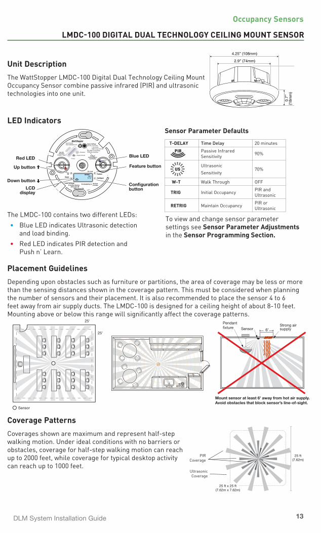
LMDC-100 DIGITAL DUAL TECHNOLOGY CEILING MOUNT SENSOR
Unit Description
The WattStopper LMDC-100 Digital Dual Technology Ceiling Mount Occupancy Sensor combine passive infrared (PIR) and ultrasonic technologies into one unit.
LED Indicators
The LMDC-100 contains two different LEDs: • Blue LED indicates Ultrasonic detection
and load binding. • Red LED indicates PIR detection and
Push n’ Learn.
Placement Guidelines
Depending upon obstacles such as furniture or partitions, the area of coverage may be less or more than the sensing distances shown in the coverage pattern. This must be considered when planning the number of sensors and their placement. It is also recommended to place the sensor 4 to 6 feet away from air supply ducts. The LMDC-100 is designed for a ceiling height of about 8-10 feet. Mounting above or below this range will significantly affect the coverage patterns.
Coverage Patterns
Coverages shown are maximum and represent half-step walking motion. Under ideal conditions with no barriers or obstacles, coverage for half-step walking motion can reach up to 2000 feet, while coverage for typical desktop activity can reach up to 1000 feet.
2.9” (74mm)
4.25” (108mm)
2.0”
(51m
m)
0.7”
(18m
m)
25 ft(7.62m)
25 ft x 25 ft(7.62m x 7.62m)
PIR Coverage
Ultrasonic Coverage
Strong airsupply6’Sensor
Mount sensor at least 6’ away from hot air supply.Avoid obstacles that block sensor’s line-of-sight.
Pendant�xture
Sensor
25'
25'
Sensor Parameter Defaults
T-DELAY Time Delay 20 minutes
Passive Infrared Sensitivity 90%
Ultrasonic Sensitivity
70%
W-T Walk Through OFF
TRIG Initial Occupancy PIR and Ultrasonic
RETRIG Maintain Occupancy PIR or Ultrasonic
To view and change sensor parameter settings see Sensor Parameter Adjustments in the Sensor Programming Section.
PIR
RETRIG
LD= Load
Up button
Down button
LCDdisplay
Feature button
Configuration button
Blue LED
Feature
Configure
11686r1
Up
Down
B-W=Blink Warning AUTO=Auto ON MAN= Manual ON
DL=Daylighting on ZN=ZoneP=Profile
Load Settings:
Red LED
Sensor Settings:T.DELAY=Time Delay 1-30 minutes OVER=Sensor OverrideW-T=Walk Through ModeTEST=Test Sensitivity
11685r2
Red LEDPIR Detect
& Push n’ LearnBlue LED
Ultrasonic DetectLoad Binding
800.879.8585www.wattstopper.com
= Passive Infrared
= Ultrasonic
Occupancy Sensors
14
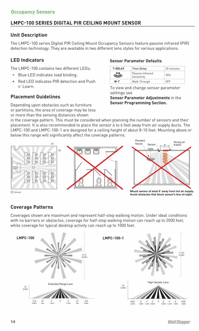
LMPC-100 SERIES DIGITAL PIR CEILING MOUNT SENSOR
Unit Description
The LMPC-100 series Digital PIR Ceiling Mount Occupancy Sensors feature passive infrared (PIR) detection technology. They are available in two different lens styles for various applications.
LED Indicators
The LMPC-100 contains two different LEDs; • Blue LED indicates load binding. • Red LED indicates PIR detection and Push
n’ Learn.
Placement Guidelines
Depending upon obstacles such as furniture or partitions, the area of coverage may be less or more than the sensing distances shown in the coverage pattern. This must be considered when planning the number of sensors and their placement. It is also recommended to place the sensor 4 to 6 feet away from air supply ducts. The LMPC-100 and LMPC-100-1 are designed for a ceiling height of about 8-10 feet. Mounting above or below this range will significantly affect the coverage patterns.
Coverage Patterns
Coverages shown are maximum and represent half-step walking motion. Under ideal conditions with no barriers or obstacles, coverage for half-step walking motion can reach up to 2000 feet, while coverage for typical desktop activity can reach up to 1000 feet.
Sensor
28'
30'Strong airsupply6’Sensor
Mount sensor at least 6’ away from hot air supply.Avoid obstacles that block sensor’s line-of-sight.
Pendant�xture
31.6’ 9.63m
15.84.8m
15.84.8m
10’3m
10’3m
5’1.5m
5’1.5m
0
Extended Range Lens10’
3.05m
31.6’ 9.63m
15.84.8m
15.84.8m
10’3m
10’3m
5’1.5m
5’1.5m
0
Extended Range Lens10’
3.05m
LMPC-100 LMPC-100-1
10’3.05m
8.63’2.6m
8.63’2.6m
6’1.8m
6’1.8m
2’0.6m
2’0.6m
4’1.2m
4’1.2m
0
17.25’5.25mHigh Density Lens
10’3.05m
8.63’2.6m
8.63’2.6m
6’1.8m
6’1.8m
2’0.6m
2’0.6m
4’1.2m
4’1.2m
0
17.25’5.25mHigh Density Lens
Sensor Parameter Defaults
T-DELAY Time Delay 20 minutes
Passive Infrared Sensitivity 90%
W-T Walk Through OFF
To view and change sensor parameter settings see Sensor Parameter Adjustments in the Sensor Programming Section.
Occupancy Sensors
DLM System Installation Guide 15
LMUC-100-2 DIGITAL ULTRASONIC CEILING MOUNT SENSOR
Unit Description
The LMUC-100-2 Digital Ultrasonic Corner Mount Occupancy Sensor features ultrasonic detection technology.
LED Indicators
The LMUC-100 has two different LEDs: • Blue LED indicates Ultrasonic detection and load binding. • Red LED indicates Push n’ Learn.
Placement Guidelines
Depending upon obstacles such as furniture or partitions, the area of coverage may be less or more than the sensing distances shown in the coverage pattern. This must be considered when planning the number of sensors and their placement. It is also recommended to place the sensor 4 to 6 feet away from air supply ducts. The LMUC-100-2 is designed for a ceiling height of about 8-10 feet. Mounting above or below this range will significantly affect the coverage patterns.
Coverage Patterns
Coverages shown are maximum and represent half-step walking motion. Under ideal conditions with no barriers or obstacles, coverage for half-step walking motion can reach up to 1000 square feet, while coverage for typical desktop activity can reach up to 500 square feet.
PIR
RETRIG
LD= Load
Up button
Down button
LCDdisplay
Feature button
Configuration button
Blue LED
Feature
Configure
11686r1
Up
Down
B-W=Blink Warning AUTO=Auto ON MAN= Manual ON
DL=Daylighting on ZN=ZoneP=Profile
Load Settings:
11987r1
Red LED blinks2x/second for Push n’ Learn
Sensor Settings:T.DELAY=Time Delay 1-30 minutes OVER=Sensor OverrideW-T=Walk Through ModeTEST=Test Sensitivity
www.wattstopper.com
Red LED= Ultrasonic Blue LED
Ultrasonic DetectLoad Binding
Strong airsupply6’Sensor
Mount sensor at least 6’ away
from strong air supply
31.6’9.63mmax.
31.6’9.63mmax.
Sensor Sensor
30’9.14m
50’15.24m
31.6 ft9.63m
22.3 ft6.79m
Minor Motion
Major Motion
Sensor Parameter Defaults
T-DELAY Time Delay 20 minutes
Ultrasonic Sensitivity
70%
W-T Walk Through OFF
To view and change sensor parameter settings see Sensor Parameter Adjustments in the Sensor Programming Section.
Occupancy Sensors

16
» Sensor Programming
LCD DISPLAY OVERVIEW - ABBREVIATIONS
DETECT RETRIGLDW T -TESTT DELAYAUTOVERMAN DL ZN P
PIRor &
Ultrasonic
Passive Infrared
DETECT RETRIGLDW T -TESTT DELAYAUTOVERMAN DL ZN P
PIRor &
Ultrasonic or Passive Infrared
DETECT RETRIGLDW T -TESTT DELAYAUTOVERMAN DL ZN P
PIRor &
Ultrasonic and Passive Infrared
DETECT RETRIGLDW T -TESTT DELAYAUTOVERMAN DL ZN P
PIRor &
Detect Trigger - Initial Occupancy
DETECT RETRIGLDW T -TESTT DELAYAUTOVERMAN DL ZN P
PIRor &
DETECT RETRIGLDW T -TESTT DELAYAUTOVERMAN DL ZN P
PIRor &
Detect Retrigger- Maintain Occupancy
Test Mode
DETECT RETRIGLDW T -TESTT DELAYAUTOVERMAN DL ZN P
PIRor &
Time Delay
DETECT RETRIGLDW T -TESTT DELAYAUTOVERMAN DL ZN P
PIRor &.
DETECT RETRIGLDW T -TESTT DELAYAUTOVERMAN DL ZN P
PIRor &
Auto ON Enabled
DETECT RETRIGLDW T -TESTT DELAYAUTOVERMAN DL ZN P
PIRor &
Manual ON Enabled
Zone
DETECT RETRIGLDW T -TESTT DELAYAUTOVERMAN DL ZN P
PIRor &
Profile
DETECT RETRIGLDW T -TESTT DELAYAUTOVERMAN DL ZN P
PIRor &
Digital Readout: Time delay minutes and seconds, load number, status
DETECT RETRIGLDW T -TESTT DELAYAUTOVERMAN DL ZN P
PIRor &
Daylighting Enabled
DETECT RETRIGLDW T -TESTT DELAYAUTOVERMAN DL ZN P
PIRor &
Override
DETECT RETRIGLDW T -TESTT DELAYAUTOVERMAN DL ZN P
PIRor &
DETECT RETRIGLDW T -TESTT DELAYAUTOVERMAN DL ZN P
PIRor &
Walk-Through Enabled

DLM System Installation Guide 17
Sensor Programming
SENSOR PARAMETERS ADJUSTMENT
View Sensor SettingsTo view the sensor settings, press quickly on the “Feature” button to cycle through each sensor parameter setting. Pressing and holding the Feature button for 3 seconds at any parameter brings you back to the Run Screen. In Run Screen the “up” button turns ON all loads bound to the sensor. The “down” button turns OFF all loads bound to the sensor.
Sensor Parameters Adjustment
Step 1: Cycle to the sensor settings. Press quickly on the “Feature” button to cycle to the sensor settings you wish to modify.
Step 2: Modify current sensor parameter settings. Once a parameter is selected, use the up/down buttons to adjust its value.
Step 3: Lock in setting. Once its value is modified, a quick press on the “Feature” button displays the next available parameter.
Time Delay (T.DELAY)The sensor holds the lights ON as long as occupancy is detected. (If the user uses a switch to turn the lights OFF the sensor holds the lights OFF until there is no motion and the time delay expires.) The time delay countdown starts when no motion is detected. After no motion is detected for the length of the time delay, the sensor turns the lights OFF. The following selections are available:
• Fixed time delay: The LCD display shows a numeric value that ranges from 1 to 30 minutes. • Override (OVER): The LCD display shows “OVER”. This setting overrides all sensor functions and
bypasses the occupancy control function of the sensor, but still allows the lights to be manually controlled with a DLM switch, if one is installed.
Note: If in override, to leave the light ON you must use arrow.
Walk-Through (WT)Walk-through mode turns the lights OFF three minutes after the area is initially occupied, if no motion is detected after the first 30 seconds. If motion continues beyond the first 30 seconds, the selected time delay applies.
Passive Infrared Sensitivity (PIR)
The LCD display shows PIR
and a numeric value ranging from 0 to 100%. You can adjust this value in 10% increments. As soon as a sensor sensitivity parameter is adjusted using the up/down buttons, you can check for detection sensitivity by watching the LEDs. The sensor does not turn loads ON or OFF; instead, it blinks the appropriate LED(s) to indicate detection.
PIR
RETRIG
Run Mode Screen
Remaining Time Delay Countdown
Con�guration
Feature
T. DELAY
W T
T. DELAY

18
Ultrasonic Sensitivity (US)
The LCD display shows and a numeric value ranging from 0 to 100%. You can adjust this value in 10% increments. If the sensitivity is 0%, the sensor will not transmit any Ultrasound. As soon as a sensor sensitivity parameter is adjusted using the up/down buttons, you can check for detection sensitivity by watching the LEDs. The sensor does not turn loads ON or OFF; instead, it blinks the appropriate LED(s) to indicate detection.
Test Mode (TEST)In this mode, the sensor turns the load OFF after 5 seconds and begins a 10 minute test period. During this test period, the time delay is 5 seconds. This short time delay allows performing a sensor walk test to define the optimum sensitivity settings and product orientation. After the 10
minute period is over, the sensor begins operating with the selected time delay. To activate the test mode: While TEST is in the sensor display, press and hold the Feature button for 3 seconds.
Detection Scheme (Dual Technology sensors only)Dual technology sensors have 16 logic configurations set by selecting one of four Trigger and one of four Retrigger combinations.
• Trigger (DETECT TRIG): The LCD display shows “DETECT TRIG” and options of technologies (see below for details). This is the method that activates a change from “standby” (area unoccupied and time delay has expired) to “occupied” (sensor detects motion).
• Retrigger (DETECT RETRIG): The LCD display shows “DETECT RETRIG” and options of technologies. This is the method indicating that the area is still occupied.
For each of these functions, you can select between the following options:
• PIR: requires detection only by PIR • US: requires detection only by Ultrasonic • PIR or US: requires detection by only one of the technologies • PIR & US: requires detection by both technologies
Sensor Parameter Settings ResetIf the user is not satisfied with the changes made to the sensor parameters, you can reset all sensor parameters to the factory default (time delay, sensitivity, detection scheme and walk-through).
Press and hold the “Feature” button for 10 seconds. The LCD display shows “CLr” to confirm the sensor has been reset.
CODES IN THE DISPLAY
E06 means that the sensor is not bound to any load. Resolution: Bind the sensor to a load.E07 means the Local Network can’t be found. Resolution: Check LMRJ cable connections.E08 means that the Local Network current is below 24VDC. Resolution: Make sure that the
maximum number of devices on the Local Network is within specs for the room controller type(s). Review the Wiring instructions on pages 2 & 3 then check to be sure cable lengths and device spacing recommendations are followed.
Call technical support if you can not clear the code, or have a code that is not listed.
PIR
RETRIG
Run Mode Screen
Remaining Time Delay Countdown
Con�guration
Feature
0
30
10 SEC.1545
555
2535
2040
50
SENSOR PARAMETERS ADJUSTMENT continued
Sensor Programming
PIRCon�guration
Feature
0
30
3 SEC.
1545
555
2535
2040
50 10
TEST
DLM System Installation Guide 19
PUSH n’ LEARN™
Enter Push n’ Learn Mode (PnL)
A Configuration button on DLM communicating devices allows easy access to WattStopper’s patented Push n’ Learn™ technology to modify the system load bindings.
Making PnL Changes from a Sensor
While any DLM communicating device can initiate PnL, with a sensor installed on the DLM Local Network additional load behaviors can be configured using the sensor’s display.
Entering PnL from a sensor:Press and hold on the Configuration button for 3 seconds. The sensor’s Red LED begins blinking rapidly (2x/second) on ALL communicating devices connected to the DLM Local Network. These Red LEDs continue to blink until the user exits Push n’ Learn mode.
- All loads in the room except load #1 turn OFF immediately after entering Push n’ Learn. - The blue status LED is solid ON at every device bound to the load when the load is ON.
Note: In Push n’ Learn, only one load is ON at a time.
Load Selection
A quick press on the Configuration button steps through the loads connected to the DLM Local Network. The LCD display shows the selected load “LD #” and its associated parameters. At this point, one load is ON, and all switch buttons and sensors that are bound to this load have their blue LED solid ON.
To unbind a sensor from a load, press the Up or Down button, and the blue LED turns OFF to indicate the sensor no longer controls this specific load. To unbind a switch button from a load press the switch button and the blue LED turns OFF.
A quick press on the Configuration button activates the next load.
MAN P
LD
MAN P
LD
MAN P
Feature
Configure
11686r1
Up
Down
B-W=Blink Warning AUTO=Auto ON MAN= Manual ON
DL=Daylighting on ZN=ZoneP=Profile
11685r1
Red LED • PIR Detection& Push n’ Learn
Blue LEDLoad Binding
Sensor Settings:T.DELAY=Time Delay 1-30 minutes AUTO=Smartset OVER=Sensor OverrideW-T=Walk Through ModeTEST=Sensitivity
www.watt
stopp
er.co
m
PIR
RETRIG
LD= Load
Load Settings:
RedLED
Con�guration Button
PIRor
RETRIG
To enter PnL press and holdthe Con�guration Buttonon any DLM device. Releasethe button when the device’s Red LED begins blinking (about 3 seconds).
Corner MountSensor
The Red LED begins blinking rapidly (2x/second) on all DLM Local Network Devices. Make adjustments per instructions.
...0
30
1545
555
2535
2040
50 10
To exit PnL press and holdthe Con�guration Buttonuntil the red LED on the device stops blinking(about 3 seconds).
0
30
1545
555
2535
2040
50 10
Red LED
Switch
Con�guration Button
Red LED
Room Controller
Con�guration Button
Ceiling MountSensor
Be sure to EXIT PnL when you are finished making load changes. If you leave the network in PnL, undesired bindings and load parameter setting changes may occur.
Sensor Programming

20
View and Modify Load Parameters
Once a load is selected, use the “Feature” button to cycle through the load parameters. (B-W is Blink Warning.)
Once a parameter is selected, use the “Up/Down” buttons to adjust its value.
Once a parameter value is modified, a quick press on the “Feature” button displays the next available parameter. (DL is DayLighting.)
A quick press on the Configuration button displays the next available load and its parameters.
Pressing and holding the Configuration button for three seconds exits Push n’ Learn.
Load Parameter Options
Operating Mode (AUTO or MAN): For each load, you can select the operating mode and choose between Automatic-ON and Manual-ON. Press the “Up or Down” button to cycle through these two options. When the Automatic-ON mode is selected, the LCD display shows “AUTO”. When the Manual-ON mode is selected, the LCD shows “MAN”.
Manual-ON: in this mode, a DLM switch is required to turn ON the load. The sensor is then used to keep the load ON, based on occupancy activity. After the time delays elapses, the switch must be used to turn the load ON, if no movement is detected within the 10 second retrigger period.
Auto-ON: in this mode, either a DLM occupancy sensor or switch can turn ON the load. A switch provides the following additional functionality:
a) The load can be turned ON by the switch and it stays ON according to the occupancy settings, including time delay. When the load turns OFF due to lack of occupancy detection, the load can be turned ON again by occupancy detection, or by switch activation.
b) When the load is turned OFF manually, the load stays OFF until the sensor time delay expires. Each occupancy detection occurring during the time delay restarts the time delay, keeping the load OFF. After the time delay expires, the sensor reverts to Auto-ON mode and the load turns ON with the next occupancy detection.
Blink Warning (B-W): When enabled “B-W” shows in the display. This function can be either enabled or disabled. When 1 minute is left on the time delay, the load controlled by the sensor turns OFF for 1 second then turns back on. This provides a visual warning before the load(s) are turned OFF by the sensor. By default Blink Warning is disabled (OFF).
AUTO
MAN
B-W
B-W
DL
LD
MAN P
PUSH n’ LEARN™ continued
B-W
Sensor Programming

DLM System Installation Guide 21
Daylighting (DL): When this function is enabled “DL” displays. This function allows specific load(s) to be bound to a DLM daylight sensor, LMLS-10x series. By default Daylighting is enabled for load 1 and disabled for all other loads.
Profile (P): This function can be viewed only and cannot be modified. It is currently not used.
DEVICE & SYSTEM RESETS
Under some conditions you may want to reset devices, loads, or the entire DLM Local Network to a known state. (To return sensor parameters to default settings - see page 18.)
•Clear Single Device Bindings
From the device you want to clear, press and hold the Configuration button for 10 seconds. When the LED turns on solid, release the button. At this point, the device is no longer bound to any load.
•Reset Single Device to Plug n’ Go Configuration
From the device you want to reset, press and hold the Configuration button for 20 seconds. The LED turns on solid after 10 seconds; when the LED begins blinking again, release the button. At this point, the device is bound to load(s) according to its PnG default.
•Clear ALL Bindings for ALL Devices on the DLM Local Network
Enter PnL mode. From any device, press and hold the Configuration button for 3 seconds. When the red LED on the device begins blinking rapidly, release the button. The red LED on every device on the DLM Local Network starts blinking rapidly.
Press and hold the Configuration button for 10 seconds. When the Red LED turns solid, release the Configuration button. At this point, none of the devices connected to the DLM Local Network are bound to a load.
Reconfigure the system as desired, then exit PnL.
•Reset ALL Devices on the DLM Local Network to Plug n’ Go Configuration
Enter PnL mode. From any device, press and hold the Configuration button for 3 seconds. When the red LED on the device begins blinking rapidly, release the button. The red LED on every device on the DLM Local Network starts blinking rapidly.
Press and hold the Configuration button for 20 seconds. The red LED turns on solid after 10 seconds; when the LED begins blinking again, release the button. At this point, all devices connected to the DLM Local Network are restored to their Plug n’ Go functionality.
LDB-WAUTO
DL P
DL
PUSH n’ LEARN™ continued
Be sure to EXIT PnL. If you leave the network in PnL, undesired bindings and load parameter setting changes may occur. To exit PnL press and hold the Config button until the red
light stops blinking, approximately 3 seconds.
» Reset Options
Sensor Programming

22
MY NOTES

DLM System Installation Guide 23
INFRARED COMMUNICATION OVERVIEW
IR-Capable Devices
DLM handheld devices use an infrared (IR) transmitter and receiver to communicate wirelessly with a Digital Lighting Management (DLM) network. A DLM handheld device is battery operated and communicates wirelessly by sending an IR signal to a DLM IR enabled device within its range and line of sight.
Handheld IR devices include controls such as the LMRH-101, LMRH-102 and LMRH-105, as well as the LMCT-100 Digital IR Configuration Tool.
To send signals to the DLM network, the user simply points the handheld remote at any IR enabled DLM device within its range and presses a button. To identify an IR enabled device, look for a dark translucent lens on the face of the device.
Helpful Communication Tips
Infrared signalling can be affected by high ambient light such as direct sunlight, floodlights, and some halogen or fluorescent lamps, as well as plasma screens.
Be sure to point the remote at a DLM IR enabled device that is within range. To test, see if you can put the local network into PnL using the remote from your current position.
• If not successful, move closer to the IR enabled local network device and more directly in front of it, or try pointing toward a different IR enabled device.
• If still not successful, turn OFF bright lights, close blinds and try again.
• If still not successful, the IR lenses on the DLM devices may be dirty. Clean the lenses with a soft material such as an eyeglass lens cleaning cloth.
» Wireless Infrared Communication
Corner MountSensor
Ceiling MountSensor
Switch
IR Receiver
Infrared Lens
LMRH-101 LMRH-102 LMRH-105 LMCT-100

24
LMCT-100 DIGITAL IR CONFIGURATION TOOL
» Configuration Tool
The LMCT-100 Digital Configuration Tool is a handheld tool for setup and testing of WattStopper Digital Lighting Management (DLM) devices. It provides wireless access to occupancy and daylighting sensors for setup and parameter changes, WattStopper Push n’ Learn™ (PnL) technology for load configuration, switch and dimmer assignment and operating parameter changes.
The LMCT-100’s display shows menus and prompts to lead you through each process. The navigation pad provides an intuitive interface to navigate through the customization fields. The LMCT-100 allows modification of the system without requiring ladders or tools; simply with a touch of a few buttons.
The LMCT-100’s IR transceiver allows bi-directional communication between DLM devices and the LMCT-100. Simple menu screens let you see the current status of the system and make sensor and load changes. You can use it to change any of the DLM occupancy sensor parameters such as sensitivity, time delay and more. With the LMCT-100 you can also change load configurations, without any new wiring. For systems including daylighting sensors the LMCT-100 can set or change the daylight level parameters. The LMCT-100 can change dimming system options such as scene assignments, fade rates, scene and load button characteristics, and other options not available through the standard user interface.
The instructions for using the LMCT-100 are provided with the unit. They are also available at www.wattstopper.com. To download the complete user guide, go to: Resources->Downloads->Installation Instructions->Digital Lighting Management.
Depending on the firmware version in the LMCT-100, the Home Menu items may be different than what is shown in the examples below. For example, to access the advanced configuration options for dimming systems, the LMCT-100 must be equipped with version 21 or higher firmware.
The version of firmware in the LMCT-100 displays on the start-up screen when you turn ON the unit.
XX.XX.XX Version number
Start-up Screen
Version 03.02.20 or 04.02.20Home Menu
S e n s o r C o n fi g u r a t i o nL o a d C o n fi g ( P n L )D a y l i g h t i n g C o n fi g
=B ATS e n s o r C o n fi g u r a t i o nL o a d C o n fi g ( P n L )D a y l i g h t i n g C o n fi gB u t t o n C o n fi g u r a t i o nD i m m i n g C o n fi g u r a t i o nA d j u s t L i g h t L e v e l
=B AT
Version 03.02.21 or 04.02.21
Dimming Options

DLM System Installation Guide 25
LMIR-100 DIGITAL INFRARED RECEIVER
Unit Description
The LMIR -100 Digital IR ceiling mount interface provides even greater flexibility and functionality to the DLM system. The LMIR-100 provides a simple remote IR portal for access by any of the LMRH IR remotes to control loads connected to the DLM system.
Placement Guidelines
The LMIR-100 provides an IR remote interface for DLM devices that are not within line of sight of the user. It accepts commands from DLM IR devices such as hand-held remote controls and forwards them to the DLM system. Choose a place for the LMIR that it is in direct view of the user. Avoid obstruction by objects such as furniture or partitions. It has a 360˚ 30-35 foot (10m) line of sight receiving range.
Operation
The LMIR-100 communicates to all other DLM devices connected to the DLM Local Network. Mount the device and connect it to the DLM Local Network. For use with DLM IR handheld remotes.
Mounting Instructions
The device has an adjustable head to accommodate multiple mounting methods and building materials or fixture walls up to 5/8” thickness.
Unit Adjustment
There are no adjustments on the LMIR-100.
Power up functionality
Upon power up the device is ready to receive signals from any of the DLM IR handheld remotes.
Specifications
Input Voltage. . . . . . . . . . . . . . . . . . . . . . . . . . . . . . . . . . . . . . . . . . . . . . . . . . . . . . . . . . . . . . . . . . . 24VDC Current Consumption . . . . . . . . . . . . . . . . . . . . . . . . . . . . . . . . . . . . . . . . . . . . . . . . . . . . . . . . . . . . . 5mAPower Supply . . . . . . . . . . . . . . . . . . . . . . . . . . . . . . . . . . . . . . . . . . . . . WattStopper Room Controllers Environment . . . . . . . . . . . . . . . . . . . . . . . . . . . . . . . . . . . . . . . . . . . . . . . . . . . . . . . . For Indoor Use Only Operating Temperature. . . . . . . . . . . . . . . . . . . . . . . . . . . . . . . . . . . . . . . . . 32° to 131°F (0° to 55°C) Storage Temperature . . . . . . . . . . . . . . . . . . . . . . . . . . . . . . . . . . . . . . . . . 23° to 140°F (-5° to 60°C) Relative Humidity . . . . . . . . . . . . . . . . . . . . . . . . . . . . . . . . . . . . . . . . . . . . 5 to 95% (non condensing)
0.77” (20mm)
0.25” (6mm)
0” - 0.50” (0 - 13mm)
1.2” (30mm)
3.9”(99mm)
1.5” (38mm)
0” - 0.5” adjustablefor mounting material
Ceiling or �xture wall
32’(10m) ceiling height
40°32’
WARNING: DO NOT USE THE DLM SYSTEM TO CONTROL LOADS OTHER THAN LIGHTING IF THE LOAD IS NOT IN VIEW OF A PERSON AT ALL CONTROL LOCATIONS. DO NOT USE DLM TO CONTROL ANY LOAD THAT MIGHT BE DANGEROUS OR CAUSE
A HAZARDOUS SITUATION IF ACCIDENTALLY ACTIVATED.
» Ceiling Mount Transceiver

26
» Handheld Remote
LMRH-102 DIGITAL IR HANDHELD REMOTE
Unit Description
The WattStopper LMRH-102 Digital IR Handheld Remote uses an infrared transmitter to send commands to a DLM IR enabled device. It allows the user to turn lights ON/OFF, to mimic functionality of other DLM switch and user interface buttons.
The LMRH-102 operates on three AAA alkaline or NiMH rechargeable batteries. It communicates with other DLM devices by sending an IR signal to any DLM IR enabled device in its line of sight, for remote personal control.
Operation
The LMRH-102 uses IR technology to control multiple zones of the DLM system. By pointing the handheld remote at any IR enabled DLM device a user can turn load(s) or zone(s) ON/OFF. Press the button on the handheld remote to turn ON a load. The LED on the LMRH-102 button turns ON.
Default Functionality
When first powered up, the top button on the LMRH-102 controls Load 1 and the second button controls Load 2. If the LMRH-102 has more buttons than there are loads or zones to control (i.e., a LMRH-102, 2 button remote is being used with only one DLM load) the second button does not control anything. If there are more than two loads on the DLM Local Network that you want to control, or you want to change the loads that are controlled by the LMRH-102 see Unit Adjustment.
Transmitting Range
32’ (10m) max. 40°
32’ (
10m
) max
.
Battery Installation
The battery compartment holds 3 standard AAA Alkaline or NiMH rechargeable batteries. Use only one type of battery; do not mix battery types in the same LMRH-102.
Specifications
Power Supply . . . . . . . . . . . . 3 AAA batteries, 1.5V alkaline or NiMH rechargeableEnvironment: Operating Temperature. . . . . . . . . . . . . . . . . . . . . . . . . . . . . . . . . . . . . . . . . . 32˚ to 95°F (0˚ to 35°C) Storage Temperature . . . . . . . . . . . . . . . . . . . . . . . . . . . . . . . . . . . . . . . . . . 23 to 176°F (-5° to 80°C) Relative Humidity . . . . . . . . . . . . . . . . . . . . . . . . . . . . . . . . . . . . . . . . . . . . 5 to 95% (non condensing)
5.1” (129mm)
0.6”
(15mm)
1.6”(40mm)
Blue LED(s)
On/Off Button(s)

DLM System Installation Guide 27
Handheld Remote
LMRH-102 continued
Unit Adjustment (optional)
The Configuration button allows the user to easily access, without tools, our patented Push n’ Learn™ (PnL) technology and simply modify the default operation of the handheld remote. In order to communicate with the DLM Local Network, the LMRH-102 must be pointed at a DLM IR enabled device.
Step 1: Enter Push n’ Learn (PnL)Open the battery compartment and locate the Configuration button as shown in the illustration.
Point the LMRH-102 at an IR enabled DLM device as you press and hold the Configuration button for 3 seconds.
• The Red LED on the LMRH-102 and ALL other communicating DLM devices begins to blink rapidly (2x/second). The Red LED will continue to blink until you exit PnL mode.
• All loads in the room turn OFF immediately after entering PnL. After 1 second, Load 1 as assigned by the Plug n’ Go feature (or the last PnL binding) turns ON.
Step 2: Load SelectionA quick press on the Configuration button while pointing the LMRH-102 at an IR enabled DLM device steps through all the loads connected to the DLM Local Network. All switches and sensors that are bound to the load that is currently ON will have their blue LED solid ON.
• To bind the load that is ON to one of the buttons on the handheld remote, press the desired button on the remote making sure that the blue LED turns ON.
• To unbind the load that is currently ON press the button with the blue LED ON, and the LED turns OFF to indicate that the button on the handheld remote no longer controls this load.
A quick press on the Configuration button activates the next load. Repeat the process until all the loads are assigned to the buttons you desire. Note that more than one load can be assigned to a button and a load can be assigned to multiple buttons.
Step 3: Exit Push n’ LearnPress and hold the Configuration button for 3 seconds, until the red LEDs stop blinking.
Reset Process
Point the LMRH-102 at an IR enabled DLM device as you perform each of these functions.
Load binding reset - To clear the unit so that it is not bound to any load:1. Make sure the DLM local network is in Normal operating mode.2. Press and hold the Configuration button in the battery compartment until LMRH device red
LEDs go solid ON (approximately 10 seconds).
Device reset - To get the unit back to its default Plug n’ Go state:1. Make sure the system is in Normal operating mode.2. Press and hold the Configuration button in the battery compartment for 20 seconds.
System Reset - To return all devices on the DLM local network to PnG:1. Put the DLM local network into PnL.2. Press and hold the Configuration button for approximately 20 seconds, until DLM device red
LEDs resume blinking rapidly (approximately 2x/second).
Point atDLM Device
Con�gurationButton
Red LED

28
LMLS-105 DAYLIGHT SENSOR - CLOSED LOOP ON/OFF
Unit Description
The WattStopper LMLS-105 is an interior photosensor that turns OFF or holds OFF electric lights if there is enough daylight. It is a low voltage device designed for Plug n’ Go integration with the WattStopper Digital Lighting Management (DLM) product family.
The LMLS-105 is designed to require minimal adjustment at startup. For more advanced applications, an onboard display and two push buttons allow for adjustments, if needed. The display is hidden under a removable cover. To assist with adjustment, the LMLS-105 displays the current light level reading.
The LMLS-105 is designed to be either ceiling- or wall-mounted. It has a wide range light sensor capable of measuring from 1 to 1400 footcandles.
Placement Guidelines
The LMLS-105 controls lights in areas that receive enough daylight that the electric lights can be reduced or switched OFF. It is important to select a location for the LMLS-105 where the daylight is representative of the daylight throughout the controlled zone. Note the path of shadows. Daylighting control will be problematic if part of a controlled zone is in shadows while another part has plentiful daylight.
When the primary source of daylight is a window (sidelighting), the LMLS-105 is typically ceiling mounted within the daylit zone which extends 12 feet or less in from the window. A good location is often between the window and the first row of fixtures. Figure A shows a typical mounting location for a sidelit application.
When the primary source of daylight is a skylight (toplighting), there are several options for mounting the LMLS-105. The recommended mounting locations are shown in Figure B.
Ideally, the sensor is mounted on the South sidewall looking North across the light well.
It could also be mounted on the ceiling next to the skylight, looking down at the floor.
A skylight may produce 5000 footcandles or more. If the sensor is mounted so that it looks up into the skylight, the daylight will exceed the maximum OFF setpoint of 1275fc which is too low for this orientation.
Mounting Instructions
The LMLS-105 is designed to be mounted in either of two ways. For suspended ceiling tile, a threaded nipple with a lock nut is attached to the LMLS-105.
» Daylight Sensors
0.65”(17mm)
1.24”(31mm)
2.4”(61mm)
Peak Sensitivity
LMLS-105
Window
Light Fixture
Typical Daylit Zone, about 12' (3.6m)
100˚
LMLS-105
Light Fixture
Skylight
100˚
1
2
100˚
Figure A
Figure B
13/16” (20mm)
Ceiling
Retaining NutPlastic Washer
LMRJ-C8 coupler (supplied with sensor)
13/16” (20mm) hole

DLM System Installation Guide 29
LMLS-105 continued
Controls and Indicators
All adjustments are made using the display and two buttons. Access the display by removing the cover. Set it safely aside. The display is oriented so that the letters are right side up when the light sensor is at the top.
Buttons
There are two buttons, one on each side of the display, labeled Menu and Select. The Menu button moves the display forward through the menus. The Select button has two functions:
1. Press and release Select to step through the adjustment choices.
2. Press and hold Select until MEM appears in the display. This locks the selection shown in the display into the sensor’s memory.
Automatic Calibration (auto cal)Auto Cal is an automatic calibration procedure for selecting an appropriate value for the ON setpoint. As part of this process, the controlled load is first turned ON for a period of two minutes to warm up the lamps. Then it is switched OFF and back ON eight times, terminating in an OFF state. To indicate to the user that AUTO CAL
is active, the LED status indicator flashes in a unique manner. At the completion of the calibration, a new value for the ON setpoint will have been selected. The results can be viewed in the ON menu.
Default Daylight Sensor SettingsON Setpoint .............7.5 fc OFF Setpoint ........... 11 fcON Time Delay ........20 seconds OFF Time Delay ...... 3 minutes
Load Binding
The daylight sensor is automatically enabled for Load 1 using the default PnG configuration. To enable/disable daylighting for any load, you can use an occupancy sensor display (see Push n’ Learn) or the LMCT-100 configuration tool (see LMCT-100 instructions).
Specifications
Voltage. . . . . . . . . . . . . . . . . . . . . . . . . . . . . . . . . . . . . . . . . . . . . . . . . . . . . . . . . . . . . . . . . . . . . . . . 24VDCCurrent Consumption . . . . . . . . . . . . . . . . . . . . . . . . . . . . . . . . . . . . . . . . . . . . . . . . . . . . . . . . . . . . 10mA Total power requirements are determined by the controlled device.Power Supply . . . . . . . . . . . . . . . . . . . . . . . . . . . . . . . . . . . . . . . . . . . . . WattStopper Room ControllersLight Sensor range . . . . . . . . . . . . . . . . . . . . . . . . . . . . . . . . . . . . . . . . . . . . . . . . .1 to 1400 footcandlesON Setpoint range . . . . . . . . . . . . . . . . . . . . . . . . . . . . . . . . . . . . . . . . . . . . . . . . . . .1 to 850 footcandlesAutomatic Deadband . . . . . . . . . . . . . . . . . . . . . . . . . . .25%, 50%, 75%, 100% (above the ON setpoint)Status Indicator . . . . . . . . . . . . . . . . . . . . . . . . . . . . . . . . . . . . . . . . . . . . . . . . Multi-function green LEDOutput signal . . . . . . . . . . . . . . . . . . . . . . . . . . . . . . . . . . . . . . . . . . . . . . . . . . . 12/24 VDC, max 120 mADimensions . . . . . . . . . . . . . . . . . . . . . . . . . . . . . . . . . . . . 2.4” diameter x 0.7” depth (61mm x 17mm)Environment . . . . . . . . . . . . . . . . . . . . . . . . . . . . . . . . . . . . . . . . . . . . . . . . . . . . . . . . For Indoor Use Only Operating Temperature. . . . . . . . . . . . . . . . . . . . . . . . . . . . . . . . . . . . . . . 50° to 104° F (10° to 40° C) Storage Temperature . . . . . . . . . . . . . . . . . . . . . . . . . . . . . . . . . . . . . . . . . 23° to 176°F (-5° to 80°C) Relative Humidity . . . . . . . . . . . . . . . . . . . . . . . . . . . . . . . . . . . . . . . . . . . . . . . . . . . . .less than 90% rh
Daylight Sensors
Mounting Screw Hole
MountingScrew Hole
Light Sensor
Status LED
MenuButton
SelectButton
FC 57
Display
13/16” (20mm)

30
LMLS-305 DAYLIGHT SENSOR - CLOSED LOOP DIMMING
Unit DescriptionThe LMLS-305 is a low voltage, indoor dimming photosensor. It provides a continuous dimming signal to 0-10VDC dimming ballasts. The LM-305 is a “closed loop” system; it considers both daylight and artificial light when adjusting light levels. It uses a sliding setpoint control algorithm to maintain the desired illuminance levels for separate night and day target setpoints. The LMLS-305 slowly raises or lowers the electric lights to avoid sudden changes that can annoy occupants.
After the LMLS-305 is installed, all adjustments are made using the LMCT-100 Digital IR Configuration Tool or the LSR-301-S. The optional remote control (LSR-301-P) allows the occupant to adjust light levels.
Placement GuidelinesPlacement of the LMLS-305 is critical to its overall performance. The photosensor must be aimed to view the area illuminated by the lights that it controls.
• Position the photosensor in a location with a light level that is representative of the entire controlled area or the least illuminated work space in the controlled area.
• Avoid installing multiple sensors in adjoining areas where the light from one controlled fixture spills over into the view of the next photosensor.
• When the primary source of daylight is a window, mount the photosensor no closer than 6 feet (1.8m) to the window and no farther away than 15 feet (4.5m). The arrow on the photosensor should point away from the window, it indicates the direction of the photosensor’s broadest view.
• In applications with direct/indirect pendant fixtures, do not mount the photosensor on the ceiling within 4 feet (1.2m) of the pendant fixtures.
• Avoid mounting the photosensor above extremely reflective surfaces such as highly polished floors or tables, if possible.
Alternate Placement
When direct/indirect pendant lighting fixtures are installed less than 10 feet (3m) from the window it may be necessary to mount the LMLS-305 so that its view is away from the nearest fixture, as shown in Figure 2.
Follow the Placement Guidelines previously described.
Mounting Instructions The LMLS-305 can be mounted to a junction box in areas where low voltage connections are required to be enclosed.
1. Drill or cut a 13/16” (20mm) hole in the ceiling tile where the photosensor is to be mounted.
2. Guide the wires and threaded tube of the photosensor through the hole.
3. Slide the plastic washer around the tube.
4. Make sure the photosensor’s view is set according to the proper placement guidelines described earlier in these instructions.
5. Tighten the retaining nut to prevent the photosensor from rotating.
Daylight Sensors
0.87”(22mm)
1.24”(31mm)
2.4”(61mm)
Ceiling
Retaining NutPlastic Washer
LMRJ-C8 coupler (supplied with sensor)
LMLS-305
Window
Lighting
6' (1.8m)min.
4' (1.2m)min.
OrientationArrow
Fig. 1: Coverage pattern and typical placement
Fig. 2: Placement in applications where lighting fixtures are within 10 feet (3m) of daylight source
Window
LightingLighting
LMLS-305
0-9'(0-2.7m)
4' (1.2m)min.
15' (4.5m)max.
OrientationArrow

DLM System Installation Guide 31
LMLS-305 continued
Photosensor AdjustmentThe photosensor must be adjusted under two conditions, Night and Day. The photosensor begins automatic dimming control after both adjustments have been completed.
Initial adjustments to the LMLS-305 are done using the LSR-301-S remote control or the LMCT-100 configuration tool (see the LMCT-100 User Guide). The LSR-301-S has 5 buttons. The LED on the remote control should light every time you press a button. The red LED on the LMLS-305 photosensor also flickers for the duration of the press.
p (up arrow): Press to raise the intensity of the lights.q (down arrow): Press to lower the intensity of the lights.Night: Press to begin and end the Night adjustment.Auto: Press to begin automatically dimming the lights.Day: Press to begin and end the Day adjustment process.
Conditions for SetupAdjust the LMLS-305 after the controlled zone is furnished and ready for move-in. Placement of furniture affects the way light reflects from various surfaces.
• Furniture, floor and wall coverings must be clean.
• Window coverings must be clean and operable.
• Remove unnecessary objects such as tools and installation materials from the view of the photosensor.
• Do not block primary sources of electric light or daylight from reaching the photosensor’s view.
Default Daylight Sensor SettingsThe photosensor provides full output until it is commissioned using the adjustment procedure.
Load BindingThe daylight sensor is automatically enabled for Load 1 using the default PnG configuration. To enable/disable daylighting for any load, you can use an occupancy sensor display (see Push n’ Learn) or the LMCT-100 configuration tool (see LMCT-100 instructions).
Burn-InFollow the lamp manufacturer’s recommendation on lamp burn-in for new lamps prior to dimming the lamps with the LMLS-305. Typical recommendations are for 100 hours of operation at 100% light output. If the lamp manufacturer’s guidelines are not followed, premature lamp failure may occur.
When it is first installed and connected to the fixtures, the LMLS-305 drives the lamps at full output until the Night adjustment has been completed. The amber LED under the photosensor’s lens flashes continuously until the Night and Day adjustments have been properly completed.
SpecificationsVoltage. . . . . . . . . . . . . . . . . . . . . . . . . . . . . . . . . . . . . . . . . . . . . . . . . . . . . . . . . . . . . . . . . . . . . . . . 24VDCCurrent Consumption . . . . . . . . . . . . . . . . . . . . . . . . . . . . . . . . . . . . . . . . . . . . . . . . . . . . . 30mA@24VDCPower Supply . . . . . . . . . . . . . . . . . . . . . . . . . . . . . . . . . . . . . . . . . . . . . WattStopper Room ControllersBallasts . . . . . . . . . . . . . . . . . . . . . . . . . . . . . . . . . . . . . . . . . . . . . . . . . . . . . 0-10VDC standard dimmingMax Ballasts Controlled . . . . . . . . . . . . . . . . . . . . . . . . . . . . . . . . . . . . . . . . . . . . . . . . . . . . . 50 Ballasts Minimum Signal to ballast . . . . . . . . . . . . . . . . . . . . . . . . . . . . . . . . . . . . . . . . . . . . . . . . . . . . . . . 0.2VDCMax Signal to ballast . . . . . . . . . . . . . . . . . . . . . . . . . . . . . . . . . . . . . . . . . . . . . . . . . . . . . . . . . . . . 10VDCDimensions . . . . . . . . . . . . . . . . . . . . . . . . . . . . . . . . . . . 2.4” diameter x 2.11” depth (61mm x 54mm)Environment . . . . . . . . . . . . . . . . . . . . . . . . . . . . . . . . . . . . . . . . . . . . . . . . . . . . . . . . For Indoor Use Only Operating Temperature. . . . . . . . . . . . . . . . . . . . . . . . . . . . . . . . . . . . . . . . . . . . . . . . . . . 50° to 104° F Storage Temperature . . . . . . . . . . . . . . . . . . . . . . . . . . . . . . . . . . . . . . . . . 23° to 176°F (-5° to 80°C) Relative Humidity . . . . . . . . . . . . . . . . . . . . . . . . . . . . . . . . . . . . . . . . . . . . . . . . . . . . .less than 90% rh
Daylight Sensors
LSR-301-S
32
» External System Interfaces
INTERFACE MODULES TO 3RD PARTY SYSTEMS
General Description
There are several optional modules for the WattStopper DLM system (DLM system) that allow integration with third-party devices or systems. These interface modules have similar form factors as described below. See individual device sections for operational information.
Mounting and Wiring
Installation shall be in accordance with all applicable regulations, wiring practices, and codes.
Interface modules are UL2043 Plenum rated. All connections are Class 2 low voltage.
If code requires that the interface module be mounted in an enclosure, it can be mounted inside a 4” x 4” junction box, inside a 2 1/8” deep (or deeper) 1-gang back box, or in a 3” or 4” octagonal box.
Wall Box MountedDin Rail Mounted
Attach the LMRJ Cable
The DLM Local Network uses free topology low voltage wiring. Interface modules can connect anywhere on the DLM Local Network.
LMRJ Cables
Loads
1
2
Line Voltage
RoomController
Occupancy Sensor
Switch
LMRL-100Isolated Relay Interface
Relay output to third party device
Interface Module
Input and/or Output to 3rd party device
2.5”(63mm)
1.6”(40mm)
2.0”(51mm)

DLM System Installation Guide 33
External System Interfaces
LMRL-100 ISOLATED RELAY INTERFACE
Description
The LMRL-100 connects to the DLM Local Network and activates its isolated relay upon any occupancy signal. Connecting a third-party’s device to the LMRL-100 relay output allows the third-party device to observe when occupancy is detected.
Operation
The LMLR-100 connects to the DLM Local Network. When occupancy is detected by any sensor on the DLM Local Network the LMRL-100 automatically closes its relay. The output from the LMRL-100 terminal can signal a third party device that there is occupancy.
Terminal Connections
RLY NC(normally closed)
RLY COM To 3rdpartydevice
Isolated Relay Terminals
Contacts rated at1 amp @ 24V AC/DC
RLY NO(normally open)
Power Up Functionality
Upon initial power up the LMRL-100 automatically “listens” for an occupancy message from any occupancy sensor on the DLM Local Network. No setup is needed.
LED indicator
The LMRL-100 contains one blue LED that illuminates when the isolated relay closes.
Specifications
Voltage. . . . . . . . . . . . . . . . . . . . . . . . . . . . . . . . . . . . . . . . . . . . . . . . . . . . . . . . . . . . . . . . . . . . . . . . 24VDCCurrent Consumption . . . . . . . . . . . . . . . . . . . . . . . . . . . . . . . . . . . . . . . . . . . . . . . . . . . . . . . . . . . . . 7mAPower Supply . . . . . . . . . . . . . . . . . . . . . . . . . . . . . . . . . . . . . . . . . . . . . WattStopper Room ControllersDLM Local Network connection . . . . . . . . . . . . . . . . . . . . . . . . . . . . . . . . . . . . . . . . . . . . . 2 RJ-45 portsIsolated relay ratings . . . . . . . . . . . . . . . . . . . . . . . . . . . . . . . . . . . . . . . . . . . . . . . .1A 24VDC/VAC, SPDT normally open (N/O), normally closed (N/C) and common outputsEnvironment . . . . . . . . . . . . . . . . . . . . . . . . . . . . . . . . . . . . . . . . . . . . . . . . . . . . . . . . For Indoor Use Only Operating Temperature. . . . . . . . . . . . . . . . . . . . . . . . . . . . . . . . . . . . . . . . . 32° to 104°F (0° to 40°C) Storage Temperature . . . . . . . . . . . . . . . . . . . . . . . . . . . . . . . . . . . . . . . . . 23° to 176°F (-5° to 80°C) Relative Humidity . . . . . . . . . . . . . . . . . . . . . . . . . . . . . . . . . . . . . . . . . . . . 5 to 95% (non condensing)
Isolated RelayTerminals
11444r1N.C.
Com
mon
N.O.Re
lay
Term
inal
s
Connect toWattStopperDigital Lighting ManagementClass 2 power source.
LED lit whenrelay active.
www.wattstopper.com Pat. Pend.
Connect to DLM local network only NOT Ethernet
Normally OpenNormally Closed Common

34
The LMIO-101 Digital Input/Output Interface allows integration of 3rd party devices to the WattStopper DLM Local Network. It sends messages such as After Hours, Shed or Force On to the DLM local network based on external inputs. It activates the isolated relay upon any signal from any user defined DLM occupancy sensor so that a 3rd party’s device can observe occupancy detection.
The LMIO-101 operates on power from the DLM local network. It contains a 24VDC isolated relay [single-pole, double throw with normally open (N/O), normally closed (N/C), and common outputs] for output to other systems. It also provides input terminal connections and options for converting input signals from 3rd party devices into load controlling messages for the DLM system.
Outputs
The isolated relay can respond to any DLM occupancy sensor on the DLM local network to provide the DLM system’s occupancy status from a specific sensor to a third party controlling device such as HVAC or other controlling systems. The LMIO-101 also provides a 24VDC, 5mA current limited output and a pilot light terminal.
Inputs
Four input terminals are provided for purposes including Force-ON/Force-OFF, load shedding and cleaning functions. Input terminals 1A, 1B, 2A and 2B are for connection of maintained or momentary switch closure inputs, or third party logic inputs. Input signals may come from a wide variety of devices including building automation systems, time clocks and key switches.
External System Interfaces
Input 2BRelay Normally Open (N.O.)
Relay CommonRelay Normally Closed (N.C.)
Ground+24VDC Input 1A
Input 1BInput 2A
Pilot Light
12248r1
Relay Active
Ch 1 Status
Ch 2 Status
Relay Bind
24V Overload
Connect toDLM local network NOT Ethernet
1 N.
O.
2 CO
M
3 N.
C.
4 GN
D
5 +2
4V
6 Inp
ut 1A
7 Inp
ut 1B
8 Inp
ut 2A
9 Inp
ut 2B
10 P
ilot
Switch ON OFF
Confi
g.
1 2
3 4
5 6
7 8
Blue LEDs
DIP Switch OptionsThe LMIO-101 has DIP switches to allow different messages to go out from third party switches to the DLM local network to control the loads bound to the LMIO-101.
Power up functionality
Upon power up, the LMIO-101 listens for a DLM occupancy message from any occupancy sensor on the local network. The occupancy message activates the internal isolated relay output.
With the default DIP switch settings (all OFF), the LMIO-101 looks for only three types of switches on Input 1A, 1B, 2A and 2B: Maintained, Momentary ON/OFF, and Momentary push button. Any positive input results in a DLM message to turn ON the relay(s) bound to that input. In the default mode, Input 1 turns ON load 1, input 2 turns ON the rest of the loads.
If you change the DIP switches to use a dry contact input switch, then input 1A and 1B are assigned to load 1. Input 2A will be assigned to the rest of the loads.
Adjustments
Load Binding to Inputs:1. Enter Push n’ Learn (PnL)2. Load selection Press and release the Configuration button
to step through the loads. As each load turns ON note which blue LEDs are lit. On the LMIO-101 the Channel 1 status LED indicates binding for Input 1 and Channel 2 status LED indicates binding for Input 2.
• To unbind an input from a load, activate the desired input by using the third party switch or dry contact closure. The blue LED turns OFF to indicate the input is no longer bound to the load that is currently ON.
• To bind the input to the load that is currently ON, activate the input using the third party switch or dry contact closure. The input’s blue LED lights indicating that it controls the load that is currently ON.
Note: If you can not activate the third party switch or the dry contact closure, you can still bind Input 1 and Input 2 to a load. Enter PnL as before and when the desired load is active toggle DIP switch #7 (for Input 1) or #8 (for Input 2) to bind the input to this load.
3. Exit Push n’ Learn
LMIO-101 DIGITAL INPUT/OUTPUT INTERFACE

DLM System Installation Guide 35
External System Interfaces
the Force-ON command is released, the next highest priority command is followed.
Highest Priority
Force-On action = Load(s) ONForce-Off action = Load(s) OFFShed action = Load(s) OFFClean action = Load(s) ONAfter Hours action = Puts the load into after hours
mode where individual load parameters switch to the assigned After Hours parameters that may be different than the normal hours parameters. After Hours parameters are programmed via the LMCS-100 application, or through network systems where a Segment Manager or BACnet BAS is used to set After Hours schedules for a load or device.
Key-Switch action = Does not allow control from any of the wall switches in the DLM local network
Lowest Priority
The exception is the Key-switch command that puts the entire system into Key-switch mode where no DLM wall switches can control any loads.
Isolated Relay BindingBy default, the LMIO-101’s isolated relay responds to any occupancy sensor on the DLM local network. The isolated relay binding process associates the relay activation based on input from specific DLM sensors. Once this process has been performed for one sensor, all other sensors are unbound from the isolated relay. For custom binding, a total of 10 occupancy sensors can be bound to a single LMIO-101 isolated relay.
Isolated Relay: Binding/Unbinding an Occupancy SensorThe sensor must broadcast its serial number over the DLM local network and the LMIO-101 must capture the sensor’s serial number within 30 seconds. You must have access to both the sensor and the LMIO-101 and be able to perform steps 1-3 within the 30 second capture window.
1. To initiate the sensor’s serial number broadcast message, go to the desired sensor and momentarily press the Configuration Button.
2. Look at the LMIO-101. • If the broadcasting sensor is not
bound to the isolated relay, the blue Relay Bind LED on the LMIO-101 blinks.
• If the broadcasting sensor is bound to the relay the Relay Bind LED on the LMIO-101 is ON solid.
3. To bind or unbind the broadcasting sensor to the LMIO-101’s isolated relay, flip DIP switch #8 ON then back OFF.
• If you unbind all sensors from the LMIO-101 it goes back to its default functionality, meaning that it responds to any occupancy sensor.
4. The capture window automatically ends 30 seconds after step 1 is complete. To bind/unbind more sensors, repeat steps 1-3.
Command Prioritization Heirarchy
Outgoing commands are basic ON/OFF commands with different priorities. The higher priority command overrides lower priority commands given by the system. Following is the command priority. For example: a Force-On overrides any OFF command given by any device in the system, to make sure that the lights remain on. When
DIP Switch
#1 #2 #3 #4
INPUT TERMINAL FUNCTIONS
Input 1A Input 1B Input 2A Input 2B
Off Off Off Off On On
On Off Off Off After Hours
Key-Switch Shed N/A
Off On Off Off After Hours
Key-Switch Clean N/A
On On Off Off After Hours
Key-Switch Force-On
N/A
Off Off On Off After Hours
Key-Switch Force-Off
N/A
On Off On Off Shed Key-Switch Force-On
N/A
Off On On Off Shed Key-Switch Clean N/A
On On On Off Shed Key-Switch Shed N/A
Off Off Off On Clean Key-Switch Force-On
N/A
On Off Off On Clean Key-Switch Force-Off
N/A
Off On Off On Force-On Key-Switch Force-Off
N/A
#5 #6 #7 #8
#5 On inverts the input from 0-24VDC to 24VDC-0 (On) for input 1A. #6 On inverts the input from 0-24VDC to 24VDC-0 (On) for input 2A. #7 See “Load Binding to Inputs” #8 See “Load Binding to Inputs” and “Isolated Relay Binding”
LMIO-101 continued

36
Please Recycle
2800 De La Cruz Blvd. Santa Clara, CA 95050
Phone: 800.879.8585 www.wattstopper.com
©2009-2010 WattStopper
10743r3 10/2010
LMRJ CABLE SPECIFICATION
WattStopper LMRJ cables are Cat 5e B-to-B pre-terminated and are available in lengths from 3 feet to 100 feet in both plenum and non-plenum rating. A 6 inch non-plenum rated jumper is available for use in multi-gang switch applications. The DLM local network does NOT use ethernet, therefore ethernet cable bend radius restrictions do NOT apply to cables in the DLM local network. WattStopper can not assure proper performance of the DLM system using any other cable. LMRJ cables are not recommended for general data use in other than DLM network applications.
150’ of cable is allowed per device; a two device network is allowed 300’, 3 devices 450’, 4 devices 600’, 5 devices 750’, 6 devices 900’, 7 or more devices up to 1,000’ maximum.
When installing multiple controllers, it is best practice to spread them throughout the DLM Local Network with devices connected to each controller, rather than all the controllers at one end with LMRC cable connections only to other controllers.
WARNING TO CONNECT A COMPUTER TO THE DLM LOCAL NETWORK USE THE LMCI-100.
NEVER CONNECT THE DLM LOCAL NETWORK TO AN ETHERNET PORT – IT MAY DAMAGE COMPUTERS AND OTHER CONNECTED EQUIPMENT.
Notice: For Class 2 DLM Devices• Connect only to a Class 2 power source.• Do Not Reclassify and Install as Class 1, or with Power and Lighting Wiring.WARNING: Do Not install to cover a Junction Box Having Class 1, 3 or Power and Lighting Circuits.
SAFETY
WARNING: Do not use the DLM system to control loads other than lighting if the load is not in view of a person at all control locations. Do not use DLM to control any load that might be dangerous or cause a hazardous situation if accidentally activated.
CAUTION: Turn the power OFF at the circuit breaker or remove the fuse before working on any electrical wiring.
PATENTS
The system and products described in this guide may be covered by one or more of the following United States patents: 5,189,393 • 5,640,113 • 6,885,300 • 7,277,012 • Other Patents Pending.
WARRANTY INFORMATION
WattStopper warranties its products to be free of defects in materials and workmanship for a period of five (5) years. There are no obligations or liabilities on the part of WattStopper for consequential damages arising out of, or in connection with, the use or performance of this product or other indirect damages with respect to loss of property, revenue or profit, or cost of removal, installation or reinstallation.
Digital Lighting Management System