Digital Aircraft Modeler Tutorialdigitalaircraftmodeler.com/Tutorials/QuickStart.pdfDigital Aircraft...
23
Digital Aircraft Modeler Tutorial DAM Quick Start DAM is far more than just a flight simulator. DAM is designed and written from the ground up to give you complete control in creating your own models and flying fields. However, even if you are a very creative user, you may want to experience the flying environment “out of the box”, before beginning your own modeling projects. This tutorial will show you how to do just that. The program includes example fields and models for you to try and to use for study. After you finish this tutorial, remember that the true joy of the program is the ability to completely build something from your own imagination. Example Files First let me mention how DAM works. DAM’s editor environment is a multi-document program. You can have several documents open at one time. There are three types of documents, a Workspace, a Field and a Model. You can declare any workspace to be your field and any other workspace to be your model. When you “Go Flying”, DAM closes the editor environment and opens the flying environment. You must have open exactly one Field to fly in, and you must also have open exactly one Model to take to the field. It is easy to declare a workspace to be a field or a model. You simply click on the corresponding button in the “Space Type” panel. This picture shows how the panel looks when you have clicked on the Model button. If you declare the space you are working in as a model and you already have another space declared to be the model, the other space will revert to a workspace. This does not change the space in any way. Declaring a workspace to be a model or a field only tells DAM which space you want to be the field and which you want to be the model when you go flying. You will find you can easily have several models loaded, and return from the flying environment to the editor environment just to change which model you are flying. Example Field and Model files were installed on your computer when you installed the DAM program. They are in the program’s folder. If you installed in the default location, they are in the following location: C:\Program Files\Sunday Flyer Software\DigitalAircraftModeler\Samples
Transcript of Digital Aircraft Modeler Tutorialdigitalaircraftmodeler.com/Tutorials/QuickStart.pdfDigital Aircraft...

Digital Aircraft Modeler Tutorial
DAM Quick Start
DAM is far more than just a flight simulator. DAM is designed and written from the ground up to give
you complete control in creating your own models and flying fields.
However, even if you are a very creative user, you may want to experience the flying environment “out
of the box”, before beginning your own modeling projects. This tutorial will show you how to do just
that. The program includes example fields and models for you to try and to use for study. After you
finish this tutorial, remember that the true joy of the program is the ability to completely build
something from your own imagination.
Example Files First let me mention how DAM works. DAM’s editor environment is a multi-document program. You can
have several documents open at one time. There are three types of documents, a Workspace, a Field
and a Model. You can declare any workspace to be your field and any other workspace to be your
model. When you “Go Flying”, DAM closes the editor environment and opens the flying environment.
You must have open exactly one Field to fly in, and you must also have open exactly one Model to take
to the field.
It is easy to declare a workspace to be a field or a model. You simply click on the corresponding button
in the “Space Type” panel. This picture shows how the panel looks when you have clicked on the Model
button.
If you declare the space you are working in as a model and you already have another space declared to
be the model, the other space will revert to a workspace. This does not change the space in any way.
Declaring a workspace to be a model or a field only tells DAM which space you want to be the field and
which you want to be the model when you go flying. You will find you can easily have several models
loaded, and return from the flying environment to the editor environment just to change which model
you are flying.
Example Field and Model files were installed on your computer when you installed the DAM program.
They are in the program’s folder. If you installed in the default location, they are in the following
location:
C:\Program Files\Sunday Flyer Software\DigitalAircraftModeler\Samples
In this folder you will find a folder named “Fields” and a folder named “Models”. Obviously, the example
fields are in the Fields folder, and the example models are in the “Models” folder. DAM comes with a
couple of example flying fields, and several example models. The examples are in their own folders. Each
example folder contains the DAM file, along with the textures used by that file, and any sound files that
might be used if they are not the default sounds. This file structure makes it convenient to download
and install new models from our website. These zip files contain the model along with required textures
and sounds. All that is needed is to unzip them. When you load them in DAM, all the required textures
and sounds will be found in the same folder as the model or field.
There is one more thing to mention. You may want to change the examples and resave them. You
should use the “Save As” option and save them to a new location. There are reasons for this:
1. This keeps the example files unchanged.
2. Newer versions of Windows will not allow you to write to the “Program Files” area where the
original examples are installed.
3. You don’t risk losing your changes when you uninstall or update DAM.
I suggest you create a new folder in your “My Documents” folder called “DAM”, and create two folders
in this DAM folder, one named “Fields” and one named “Models”. When you choose “Save As” and the
file requester opens, you can save your changed files to this location. You can also use this location for
the models and fields you download from our website, and of course, for your own creations!
The location you choose to save your files does not have to be in your documents folder. You can use
any location you choose, including external and jump drives.
Load a Field Start the program by double clicking the DAM icon. When the program starts, you see a multi document
interface with an empty document.
Click one of the “Open” buttons. There is one on the Quick Access Toolbar at the top of the window
frame. There is also one in the drop down menu available when you click the large round DAM logo. The
file requester will open. Navigate to the Samples folder in the path described above.
If you are not familiar, note that you can find the “C:” drive in “Computer”.
You will see folders for fields, models, sounds and textures. The sounds and textures folders hold the
default sounds and textures that the program loads each time you start it. The fields and models folders
hold the example field and model files that were installed with the program.

Open the Fields folder, then the folder named “Home Field”. You will see a file named
“Field_Home.dam”. Double click this file. The file requester will close and DAM will load the file.
You are looking at the objects in the home field example. There is a terrain (ground), house, barn, some
cows and some trees. We won’t worry about how these were made. You will learn all about it when you
read the 3rd tutorial, “First Flying Field”.
You are in the editing environment. The objects in this workspace are listed in the object window on the
left. You can select them by clicking on them, and unselect them by clicking in an empty area in the

object list window. You can also right click on an object and choose various commands from the context
menu that opens. Don’t do anything for now.
You see 3 orthogonal arrows. These are not objects in the field. They are always present in each
workspace, and point along the positive X (red), Y (white) and Z (blue) directions. They originate at the
origin (coordinate 0,0,0). This is the location that the model always sits at when you first go to the field
to fly.
Notice that the workspace you loaded is already declared to be a field. You can navigate around the
editing workspace with the mouse:
1. Rotate: press and hold the left mouse button while dragging the mouse.
2. Pan: press and hold the mouse wheel while dragging the mouse.
3. Zoom: roll the mouse wheel
4. Center an object: double click the left mouse button on any point on any object.
5. Center and flat view: double click the left mouse button on any point on any object while
holding down the shift key.
6. Zoom all: use the small menu arrow at the bottom of the “Rotate” button in the “View” panel
and choose the “Zoom All” command from the menu.
NOTICE that for a workspace to be used as a field it must have a terrain (ground). This is a special object
that is created with the terrain tool. Don’t worry about that now. You will learn how to make one for
your own fields in the “First Flying Field” tutorial. This workspace already has one.
Load a Model Let’s load a model to take to home field and fly. Once again click the “Open” button. Navigate to the
Samples folder again but this time open the models folder.
Open the “Stearman” folder. You will see two DAM files. “Stearman.dam” is the model we will fly.
“Stearman_Plans.dam” is the file that contains the plans that we used to draw the model. It is there for
you to load and use as a learning example later.
Double click the “Stearman.dam” file. The file requester will close and DAM will load the model file.
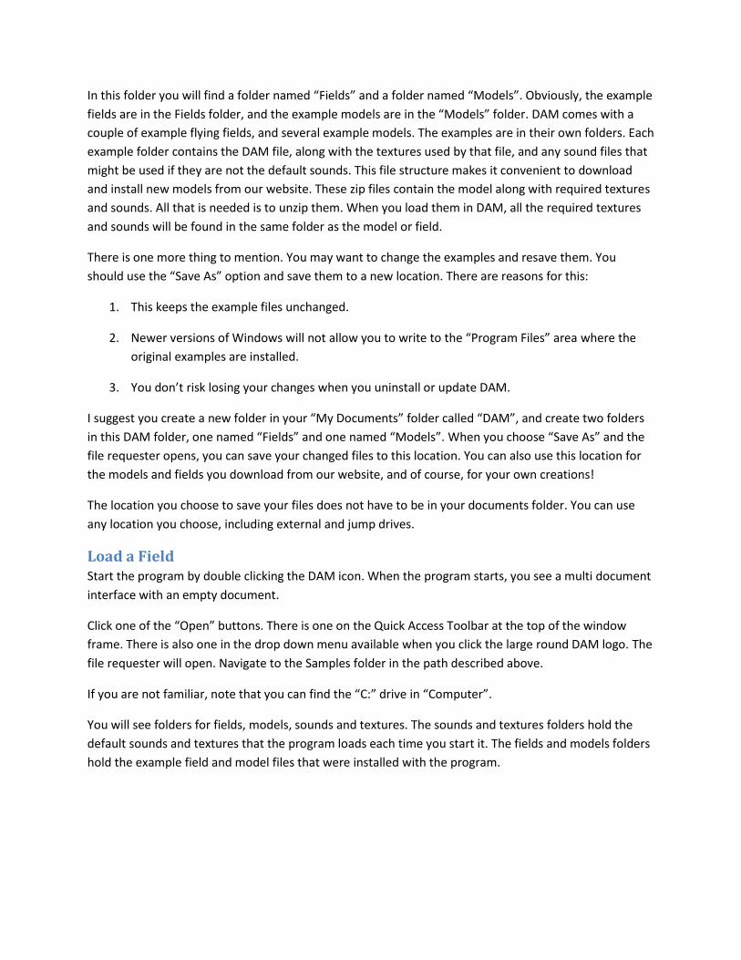
You are looking at a typical model in the editing environment in DAM. As with the field, the objects in
the model space are listed in the object list window at the left. As an aid, the objects are colored based
on their function. Engines are red, control surfaces are green and smoke sources are blue.
You can rotate, pan and zoom, just like you did in the field space.
DAM was written to take advantage of the standard Windows Multi Document Interface. Notice that
you now have 3 workspaces open. You can tell because there are three tabs above the editor window.
You switch between them by clicking on the tabs. You can also see more than one at a time by dragging
a tab to the edge of the editor window and letting go. If you want to see only one space again, you can
drag the tab(s) back to be alongside the other tab(s).

You can also copy and paste objects between workspaces, which makes it very convenient to work on
different parts in their own workspace, then move them to the field or model space.
Again, don’t do anything now. You will learn all about making your own model in the 2nd tutorial, “First
Model”.
NOTICE that for a workspace to be used as a model it must have a motor. This is a special object that has
been declared to be an engine. Don’t worry about that now. You will learn how to make one for your
own models in the “First Model” tutorial. This model already has one.

Calibrate Your Controller This is the most time consuming and perhaps most difficult part of the quick start, but it is IMPORTANT.
You must tell DAM about your controller, or you will not be able to fly your model. Before the first time
you take a model to a flying field, you must calibrate your controller or joystick. There are some basic
things we should talk about first.
When an airplane is flying, you need to steer it around the sky. To do this you only use three main
control surfaces, the Aileron, the Elevator, the Rudder, and of course, you use a Throttle to control the
engine speed.
If you are unfamiliar with control surfaces, look at the illustration. The control surfaces for each motion
are colored red, and the motion that control surface creates is shown by the green arrows. Make sure
you understand these motions and which control surface you use for each.
Elevator
The Elevator controls the “Pitch”. In level flight, down elevator lowers the nose of the airplane while up
Elevator raises the nose.
Rudder
The Rudder controls the “Yaw”. In level flight, left rudder turns the nose of the airplane to the left while
right rudder turns the nose of the airplane to the right.
Aileron
The Aileron controls the “Roll”. Left aileron lowers the left wing while raising the right wing. Right
aileron lowers the right wing while raising the left wing.
Throttle
The Throttle controls the engine speed, which makes the model fly faster or slower. It can be used to
control altitude. Fly faster and the wing creates more lift, raising the model higher into the sky. Fly
slower and the wing creates less lift, allowing it to descend.

On some models you can also control Flaps, which slow the airplane, especially during landing, Retracts,
which raise and lower the wheels, and Smoke, which is used to create a decorative path showing where
the airplane has been.
There are two types of input signal devices on your joystick, digital and analog.
Digital: The first type of input device is called a digital control. It takes the form of a button, top hat, or
sometimes a 4 or 8 way rocker. It has only 2 states, on or off.
Analog: The second type of input device is called an analog control. It takes the form of a knob, wheel,
or stick. It has an unlimited number of values within a set range.
You need both types of input devices to control your model in DAM.
These DAM controls require one analog signal each
Aileron
Elevator
Rudder
Throttle
Flap (if have 5th analog available)
These controls require a digital button
Retracts
Smoke
Flap (if do not have 5th analog available)

Controller Types
There are three basic styles of joysticks that you can use with DAM.
Dual Action – these are often called “Gamepads”, and have two joysticks each
with two axes (four analog signals) and several digital buttons. The “Dual Action” gamepads are not ideal
for use with flight simulators, but they do work ok. Their analog sticks are stubby, and as a result it is a
little more difficult to get a feel for their position. However with some experience, they are quite
useable, and they are cheap and available almost anywhere.
“Imitation Transmitter” – these are made to look like RC transmitters. They have
two joysticks each with two axes (four analog signals) one or more additional analog knobs (one analog
signal each) and one or more digital buttons. The “Imitation Transmitter” is preferred if you are using
DAM to help you learn to fly Radio Control models since the position and feel of the sticks matches what
you will experience with your actual RC transmitters.
“Flight Simulator” – these have a single tall twist grip joystick (three analog signals),
one knob or dial (one analog signal), and several digital buttons. The “Flight Simulator” styles work
extremely well, although they present you with a control ergonomic that is not yet duplicated by the
real world radio control equipment available. These joysticks became popular as a control solution for
flight simulators like the popular Microsoft Flight Simulators. This style of controller is actually less
“noisy” than the imitation transmitter controllers I have tested. An example of this type is the Microsoft
Sidewinder Precision Pro or Precision 2, or the similar models from Logitech, etc.

Stick Conventions
If you are using a “Dual Action” style controller the convention for stick orientation is to use the left
stick up/down to control throttle, the left stick left/right to control rudder, the right stick up/down to
control elevator, and the right stick left/right to control the ailerons.
If you are using an “Imitation Transmitter” style controller the convention for stick orientation is called
“Mode 2”. In mode 2, the left stick up/down controls throttle, the left stick left/right controls rudder,
the right stick up/down controls elevator, and the right stick left/right controls aileron.
If you are using a “Flight Simulator” style controller, the convention is to use forward/backward for
elevator, left/right for aileron, twist for rudder, and the wheel or knob for throttle.

Calibration
Plug the joystick you want to use into the USB port before you start DAM.
Start DAM by double clicking the icon, or any other method you prefer.
Activate the “Tools” category and click on the “Calibrate Joystick” button in the “Defaults” panel. The
Joystick Calibration window will open.
The text in the window tells you what to do to calibrate your joystick.
For each control you will click in the box to the left of the control you want to assign to a stick on your
controller. Remember, we want to use an analog input for the top four controls.
Analog Inputs:
For an example, let’s do the elevator.
Check the box for “Elevator”. This tells DAM you are going to move the stick you want to use for
the elevator. Move the stick you choose to the full “up” position and then to the full “down”
position. Do this two or three times, then uncheck the box. When you move the stick, DAM
watches to see which stick you are moving and assigns it to the elevator. It also looks to see
what the lowest position of the stick is, and the highest position, and remembers them. Later, at
the flying field DAM can tell how much elevator you want to use, and which direction to deflect
the elevator.
Now do the same thing for the Aileron, Rudder and Throttle.

Analog Flaps: If you have another analog input available, do the Flaps now, moving the stick or
knob or wheel you want to use for the flaps. If you do not have another analog input available,
wait and assign the flaps under Digital below.
Digital Inputs:
You assign the digital inputs in much the same way, except instead of moving the stick all the
way back and forth, you simply press the button you want to use.
Do the “Retracts” first. Check the box at the left. Now click the button you want to use a few
times. You will see the racetrack gadget register the click once DAM has identified which button
you are clicking. If the button is the type that stays set, you want the latch to be off. If it is the
type that does not stay set, you want to turn on the “Latch”.
Go ahead and do the “Smoke” using the same method to another button. If you are out of
buttons, you can assign the smoke to the same button as the retracts, and reverse one of them
so that you have smoke when the gear are up, and the smoke stops when the gear are down.
Digital Flaps: if you only have 4 analog inputs, turn on the “Digital” button under the Flaps and
use the same method to assign the flaps for your controller.
When you have all of your inputs configured, move them all a few times and watch the racetrack
gadgets to make sure you have them set up the way you want.
Saving Calibrations
DAM will remember the configuration you used last when you restart the program, so if you are only
going to use one joystick or controller, it is not necessary to save your configuration. However, if you are
going to use more than one joystick or controller, you have the option of saving this configuration. Save
it to a location that you will remember, and give it a name that helps you know which controller it is for.
If you switch controllers, you can load the configuration file for the controller you have attached to the
computer.
Save your file with a name you will recognize for the controller you have calibrated.
Click “OK” to close the Joystick Calibration window.

Go Flying As stated earlier, all that is required to go flying is to have a field and a workspace loaded. We now have
them, so we can go flying.
If you are still in the “Tools” category, return to the “Home” category. Make sure your throttle is at
minimum. Click on the “Go Flying” button in the “Space Type” panel.
The DAM editor multi document interface window will close and the flying field window will open. You
will see the model sitting on the ground at the flying field. The view of the model you see will depend on
whether the field has chase mode turned on. Press the “f” key to toggle chase mode. When you find
your viewpoint directly behind the model, you are in chase mode. When you are not in chase mode, the
pilot’s position does not move with the model. We’ll talk a little more about chase mode and fixed
position later.
View of model from fixed pilot’s position

View of model from chase position
You can use the keypad to alter the pilot’s position. The keys do different things depending on whether
you are in chase or fixed position. NOTE: these features are only available if you are using a joystick or
controller.
1. In fixed pilot position you can control the pilot position in the flying field by using the number
pad.
a. The 7 and 9 control our X position (left/right)
b. The 4 and 6 control our Y position (in/out)
c. The 1 and 3 control our Z position (up/down).
d. Note that the pilot’s position can be different for each model, and is saved with the
model file so it is remembered next time you fly that particular model. You can also set
the position numerically if you want. This will be covered later in the “First Model”
tutorial.
2. In chase mode, the keys have different functions
a. The 1 and 3 keys control the distance to the model
b. The 4 key sets the pilot position to be always North of the model (press the 4 key again
to exit this mode)

c. The 6 key sets the pilot position to be always South of the model (press the 6 key again
to exit this mode)
Remember, the Number Lock must be ON for the keys to be recognized. On most keyboards, this key
will be in the area of the number pad, and will be labeled “Num Lock”.
Press the “f” key so that you are not in chase mode (you will see the model from the side, not behind).
Position the pilot’s position so that the view looks similar to that in the previous fixed pilot position
picture.
Flying When you are ready, slowly advance the throttle until it is at full. You will hear the engine react, and see
the model run down the field and lift off. Pull back on the elevator stick, not too much, just enough to
allow the model to climb out. Wait until the model has achieved some altitude, but don’t wait so long
that the model gets too hard to see. It will be getting smaller, just like at the real field! You need to turn
the model back toward you. Let’s make a left turn.
There are two ways to make a simple left turn.
1. Aileron turn: bank the model to the left by pulling the aileron stick to the left until the model is
at about a 20 degree angle, then let go of the aileron stick as you add elevator. The model will
turn toward you. Use enough elevator to turn the model, but try not to let the nose go high, or
go low. When the model has made the full 180 degree turn, use right aileron to level the wings.
Continue working with the elevator and aileron to keep the model level. Remember the aileron
and rudder controls are reversed when the model is pointed toward you!
2. Rudder turn: begin to add left rudder. You will see the model turn toward the left, bank slightly
to the left, and the nose will drop. Add elevator to keep the nose level. Don’t let it get too high.
Don’t let it get too low or the model will gain speed and may hit the ground. Continue holding
left rudder and using the elevator as needed until the model is pointed back at you. Level the
wings with right rudder (or right aileron). Continue working with the elevator and aileron to
keep the model level. Again, remember the ailerons and rudder are reversed when the model is
pointed toward you!
You may be surprised to find that neither of these methods is acceptable in a real airplane. If you are
piloting a real plane and turn as in #1, when you bank the plane left 20 degrees, you will slide to your
left in the seat. This can be uncomfortable, especially for your passengers. If you just kick in the left
rudder as in #2, you slide in your seat to the right from the centrifugal force. Again, this can be
uncomfortable. The proper way to turn the plane is a synchronous use of all three controls, rudder,
aileron and elevator, to keep the pressure straight down in your seat, and keep sliding to a minimum.
It’s amazing how much practice and discipline it takes to make a simple turn properly. Some of us never
take the time to get it “right” and just have fun jerking the model around the sky. That’s fine, but once
you know what is involved, it is really amazing to watch some of the more experienced pilots make
simple perfect turns.
After you have the model pointed back at you, allow it to continue past for a ways, then turn the model
around 180 degrees again so it is pointed back at you. This time when the model is pointed at you, and
you want to level the wings with the aileron, try pointing the stick toward the low wing. This helps you
remember which way to move the stick to level the model. To level the model, when the model is
pointed at you – toward the high wing, and when the model is pointed away from you – toward the low
wing. Easy!
After you have made a few passes, let’s land the plane. Fly the model some distance away from you and
turn toward yourself again. Cut the throttle to about half. You will see the plane begin to descend. The
nose of the model will begin to angle downward. Pull in some elevator to raise the nose so the model is
back to level, or even slightly nose high. You should see the model begin to slow down and lose altitude.
If not, lower the throttle a little more. Keep the model’s wings level. Steer the model by a moderate use
of the rudder if needed. Watch the model’s descent and try to estimate where it will land. If it is going to
land too short, you can add just enough throttle to keep it airborne until it is closer, then back down the
throttle so the model touches down right in front of you. Try “pulsing” the throttle, with short, quick
bursts of power. For some reason pulsing the throttle makes it easier to judge the amount of power you
need. This is true when flying your real models at your local flying field, and it is true flying your digital
models in DAM.

Practice your takeoffs and landings until you are reasonably confident in your ability to perform these
basic tasks.
Remember while you are flying to turn the smoke on and off with whichever switch you set up for
smoke control when you calibrated your controller. Later you will learn that you can color the smoke.
You’ll learn how in the “First Model” tutorial.
Have you noticed the clouds are moving? You’ll learn how to control this in the procedural sky section in
the “First Flying Field” tutorial.
When you have some proficiency, try flying with the pilot’s position in chase mode by tapping the “f”
key. Landing and taking off in this mode can be a little easier. It’s a shame we don’t have this mode at
our real flying fields. Remember to try the “fixed” North and South (of the model) pilot positions by
pressing the number pad 4 and 6 keys while in the chase mode.
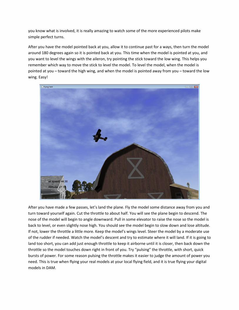
This picture shows the Stearman model about to fly between the house and barn as seen in chase mode.
While you are in chase mode, fly around the field and notice that the trees are actually flat, just like they
are in the editor. This method of displaying complex objects by using a texture on a single polygon is
called “Billboarding”. It is a very efficient method to use when you want to render a complex scene as
fast as possible. DAM uses Billboarding for group objects, and for some sky objects. You’ll learn how to
make your own in the “First Flying Field” tutorial.

You may also notice that you can crash into the house and barn, and the ground, but you can fly through
the trees and cows without crashing. Each object in DAM can participate in crashing or not, based on
what you specify. In this field, we have turned crashing on for the buildings and ground, and off for the
tree and cow group objects. You can turn crashing on/off with the “Allow Collision” button in the
“Surface Properties” window (you get there by right clicking any object and choosing “Surface
Properties” from the context menu). Remember that there is a great deal of calculation required each
frame to test for collision between objects. By being able to choose which objects are tested, you can
make the scene render even faster. For instance, there really isn’t any reason to test for object collision
for the wheel struts, muffler, dummy motor, wing struts, wing pants, and so on. As long as you test for
the main objects, wing, rudder, elevator, spinner, you will detect all collisions. You’ll think about this
more as you build your own model in the “First Model” tutorial later.
Included Model Examples When you loaded the Stearman, you saw several other example model folders. DAM installs with model
files that are intended to be examples for you to study and learn from when making your own models.
Don’t forget to look at the Authors Notes for the models. There may be interesting information about
each model there.
At the time of this writing the examples include the following.
Helicopter
The engine vectors, power and direction of thrust, are configurable, making it a simple matter to create
vertical takeoff models of all types. The included helicopter model illustrates this very nicely. The open
tail boom structure shows how to use the “cut” feature of textures to make an elegant complex
structure that is efficient and fast to render. The bell canopy shows how to use alpha channels in
textures to modify transparency. The main and tail rotors demonstrate one interesting solution to
showing “trails” along with a “solid” rotor. Also take notice of the subtle realistic smoke.

Lublin
This “Slow Flyer” example shows how to set up an engine to have a realistic feeling amount of power. Of
note is the use of a simple texture to simulate wing ribs under covering. The use of the “decal” texture
mode is seen in the application of logos on the wings and fuselage. There is also an interesting use of the
wheel positions to allow a single wheel model that uses one wingtip as a “wheel” when on the ground.
This is similar to how a model with a single skid instead of wheels could be built.
The second file shows the plan that was used to build the model, along with the polygons traced from
the plan and the objects that were extruded or revolved from the polygons. You will learn how to use
the trace mode to load your plans and draw from them when you work through the “First Model”
tutorial.
Pattern Flyer
This model was designed to “fly on rails” as models of this type are known to do. As you gain experience,
you may want to try making the flight simulation even better by adjusting the model parameters. The
model illustrates one method to make the wheel pants participate in the retract motion.
If you load a Cubemap, make sure you assign the canopy to reflect it. The effect is quite dramatic.
The second file shows the plan that was used to build the model, along with the polygons traced from
the plan and the objects that were extruded or revolved from the polygons. You will learn how to use
the trace mode to load your plans and draw from them when you work through the “First Model”
tutorial.

Profile Jet
This model shows how to build a “profile” fuselage. Also shown is the method to make “right reading”
logos on either side of the fin and rudder using a single texture.
The model is set up to be capable of level flight speeds in excess of 230 mph (!) so it is great fun to do
high speed fly bys. It is also possible with judicial throttle control (and a lot of practice) to slow the
model and pull into a vertical hover. The smoke trails during the hover can be dramatic.
Because of the high speed of this model, the camera lag can also be quite dramatic. The model can
easily fly out of frame. You may want to use a small lag, or even a setting of 0.0 (no lag) when flying the
profile jet.
Of note is the configuration of the engine to simulate a jet-like operation. The simulation is quite
realistic.
The model shows one way to simulate flame, using two smoke objects, one for an intense flame that
changes from red to yellow along its length, and a second that creates a convincing smoke trail.
Rocket
The rocket example is included as a type of model you may not have considered. The file shows one way
to create a model that flies with no controls other than throttle. Take it to the flying field. Turn on the
smoke and give it full throttle. Stop the throttle when the model has reached the desired altitude. The

simulation is quite pleasing, both in fixed pilot position and quite dramatic if you change to chase
camera near the apogee.
If you are interested in this type of flight, you could add control surfaces to the rocket so that you could
fly it around as a “glider” after the ascent instead of just watching it fall back to the ground. You could
also build more sophisticated model for this purpose. It would be fun to fly and quite different from the
usual model.
Small Biplane
One of my favorite RC models was a small biplane that used a Cox 0.51 TeeDee engine. It didn’t have a
lot of power, but that little engine could really rev up. Top speed of the little bipe felt absolutely
blinding!
This model simulates the type of flight I saw from the little bipe pretty well. Give it time to get up to
speed in level flight coming at you, and then very sharply pull in full left aileron, left rudder and up
elevator while at the same time dropping the throttle to minimum for a wonderful, very fast snap roll.
Practice letting the model do two snaps, then stop the roll in level flight and continue by.
Of note is also the simple line oriented texture used to decorate the model. This approach to texturing
could also be used very effectively as a second blend texture in decal mode, overlaying a more
photographic main texture.
Stearman

The Stearman model is a spunky little model to fly. With enough power to sustain vertical flight, it
proves to be a little “nose heavy” to hover, but with some practice it can be done. Loops, rolls and flat
spins are fun and convincing. Inverted low speed inverted passes are dramatic, especially when close to
the pilot position. With practice, you can also get this model to do very nice hammer head turns. With a
LOT of practice you can even get the model to perform sustained rolling harriers.
Trainer
This model has the predictable flight characteristics, well behaved takeoffs and gentle landings you have
come to expect from your favorite trainer. If you are just learning RC, this is a good place to start. While
not overpowered, it still has enough spunk to do a simple loop. Rolls and inverted flight are realistic. The
feel of the low power glide is rewarding. Rudder turns exhibit induced roll tendencies, very much like
one of my old trainers, still hanging on the garage wall.
The smoke is a little heavy for the model. You might want to reduce the amount and persistence.
Of note is the way the logo was made “right reading” on each side of the fin and rudder using a single
texture.
Conclusion You now have a pretty good idea of what the flying environment of DAM is like. But this is only half of
what DAM is about! As we stated at the beginning of this tutorial, DAM is far more than just a flight
simulator. DAM is designed and written from the ground up to give you complete control in creating
your own models and flying fields.
The true joy of the program is the ability to completely build something from your own imagination.
Original Design You are the reason we wrote this fine program, and the reason we will continue refining and adding
features for future releases. You have become part of a group of intelligent and talented people that
enjoy the nearly unlimited potential for expressing your creativity in the wonderful hobby of radio
control, and especially in our DAM digital playground.

Others in the DAM community want to see and enjoy your original work. When you make a model or a
field you are proud of, we can help you show it off. Zip the model or field file along with its texture files
together and email the zip file to us with the word “Model” or “Field” in the subject line. There are
simple links on our website that make it easy. We will take a look, and if we think it is something others
would like to see, we’ll publish it so every DAM user in the world can download it for free to fly and
enjoy. In this way we all get access to the creative efforts of uncounted talented DAM users from all
over the world, and get to play with, and be inspired by their creations.
There is also an opportunity to create plans for others to work from. Look at the simple plan we used to
create our trainer in the previous tutorial. This extremely simple plan format is ideal, and all that is
required to catch the interest of a lot of DAM users. If you like drawing these plans and would like to
share them with the DAM community, email them to us with the word “Plan” in the subject line. We will
look, and if we think it is something others would like to see, we’ll publish it for every other DAM user to
download and work from for free.
Now have fun! It is what DAM was created for.
Digital Aircraft Modeler
Sunday Flyer Software, LLC