Digidesign 888|24 I/O Audio Interface - Digidesign Support...
26
Digidesign Inc. 3401-A Hillview Avenue Palo Alto, CA 94304 USA tel: 650·842·7900 fax: 650·842·7999 Technical Support (USA) 650·842·6699 650·856·4275 Product Information 650·842·6602 800·333·2137 Fax on Demand 1-888-USE-DIGI (873-3444) World Wide Web www.digidesign.com Digidesign FTP Site ftp.digidesign.com Digidesign 888|24 I/O Audio Interface Installation Guide
Transcript of Digidesign 888|24 I/O Audio Interface - Digidesign Support...
Digidesign888|24 I/O Audio Interface
Installation Guide
Digidesign Inc.3401-A Hillview Avenue
Palo Alto, CA 94304 USAtel: 650·842·7900fax: 650·842·7999
Technical Support (USA)650·842·6699650·856·4275
Product Information650·842·6602800·333·2137
Fax on Demand1-888-USE-DIGI (873-3444)
World Wide Webwww.digidesign.com
Digidesign FTP Siteftp.digidesign.com
Copyright
This User’s Guide is copyrighted ©1999 by Digidesign, a division of Avid Technology, Inc. (hereafter “Digidesign”), with all rights reserved. Under copyright laws, this manual may not be duplicated in whole or in part without the written consent of Digidesign.
DIGIDESIGN, AVID and PRO TOOLS are trademarks or registered trademarks of Digidesign and/or Avid Technology, Inc. All other trademarks are the property of their respective owners.
All features and specifications subject to change without notice.
PN 932707455-00 REV A 11/99
Communications & Safety Regulation Information
Compliance Statement
The model 888/24 I/O complies with the following standards regulating interference and EMC:• FCC Part 15 Class A• EN55103 – 1, environment E4• EN55103 – 2, environment E4• AS/NZS 3548 Class A• CISPR 22 Class A
Radio and Television Interference
This equipment has been tested and found to comply with thelimits for a Class A digital device, pursuant to Part 15 of theFCC Rules.
Communications Statement
This equipment has been tested to comply with the limits for aClass A digital device. Changes or modifications to this product not authorized by Digidesign, Inc., could void the Certification and negate your authority to operate the product. This product was tested for CISPR compliance under conditions that included the use of peripheral devices and shielded cables and connectors between system components. Digidesign recommends the use of shielded cables and connectors between system components to reduce the possibility of causing interference to radios, television sets, and other electronic devices.
Safety Statement
This equipment has been tested to comply with USA and Canadian safety certification in accordance with the specifications of UL Standards; UL813 and Canadian CSA standard; CSA C22.2 No.1-M90. Digidesign Inc., has been authorized to apply the appropriate UL & CUL mark on its compliant equipment.
Important Safety Instructions
When using electric or electronic equipment, basic precautionsshould always be followed, including the following:• Read all instructions before using this equipment.• To avoid the risk of shock, keep this equipment away from
rain water, and other moisture. Do not use this equipment if it is wet.
• The equipment should only be connected to the correct rating power supply as indicated on the product.
• Do not attempt to service the equipment. There are no user-serviceable parts inside. Please refer all servicing to authorized Digidesign personnel.
• Any attempt to service the equipment will expose you to a risk of electric shock, and will void the manufacturer’s warranty.
• The product should be connected only to the correct power supply as indicated on the product.
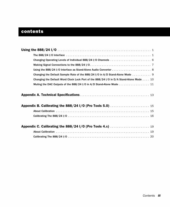
contents
Using the 888/24 I/O . . . . . . . . . . . . . . . . . . . . . . . . . . . . . . . . . . . . . . . . . . . . . . . . . . . . . . . 1
The 888/24 I/O Interface . . . . . . . . . . . . . . . . . . . . . . . . . . . . . . . . . . . . . . . . . . . . . . . . . . 1
Changing Operating Levels of Individual 888/24 I/O Channels . . . . . . . . . . . . . . . . . . . . . . . . 6
Making Signal Connections to the 888/24 I/O . . . . . . . . . . . . . . . . . . . . . . . . . . . . . . . . . . . . 7
Using the 888/24 I/O Interface as Stand-Alone Audio Converter . . . . . . . . . . . . . . . . . . . . . . . 8
Changing the Default Sample Rate of the 888/24 I/O in A/D Stand-Alone Mode . . . . . . . . . . . 9
Changing the Default Word Clock Lock Port of the 888/24 I/O in D/A Stand-Alone Mode . . . . 10
Muting the DAC Outputs of the 888/24 I/O in A/D Stand-Alone Mode . . . . . . . . . . . . . . . . . . 11
Appendix A. Technical Specifications . . . . . . . . . . . . . . . . . . . . . . . . . . . . . . . . . . . . . . . . . 13
Appendix B. Calibrating the 888/24 I/O (Pro Tools 5.0) . . . . . . . . . . . . . . . . . . . . . . . 15
About Calibration . . . . . . . . . . . . . . . . . . . . . . . . . . . . . . . . . . . . . . . . . . . . . . . . . . . . . . . 15
Calibrating The 888/24 I/O . . . . . . . . . . . . . . . . . . . . . . . . . . . . . . . . . . . . . . . . . . . . . . . . 16
Appendix C. Calibrating the 888/24 I/O (Pro Tools 4.x) . . . . . . . . . . . . . . . . . . . . . . . 19
About Calibration . . . . . . . . . . . . . . . . . . . . . . . . . . . . . . . . . . . . . . . . . . . . . . . . . . . . . . . 19
Calibrating The 888/24 I/O . . . . . . . . . . . . . . . . . . . . . . . . . . . . . . . . . . . . . . . . . . . . . . . . 20
Contents iii

iv
888/24 I/O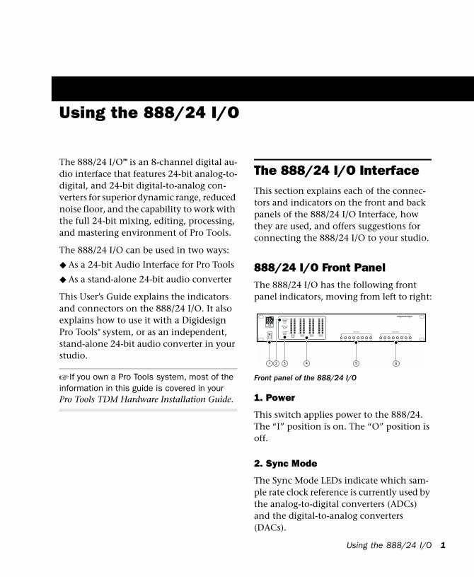
Using the 888/24 I/O
The 888/24 I/O™ is an 8-channel digital au-dio interface that features 24-bit analog-to-digital, and 24-bit digital-to-analog con-verters for superior dynamic range, reduced noise floor, and the capability to work with the full 24-bit mixing, editing, processing, and mastering environment of Pro Tools.
The 888/24 I/O can be used in two ways:
◆ As a 24-bit Audio Interface for Pro Tools
◆ As a stand-alone 24-bit audio converter
This User’s Guide explains the indicators and connectors on the 888/24 I/O. It also explains how to use it with a Digidesign Pro Tools® system, or as an independent, stand-alone 24-bit audio converter in your studio.
☞ If you own a Pro Tools system, most of the information in this guide is covered in your Pro Tools TDM Hardware Installation Guide.
The 888/24 I/O InterfaceThis section explains each of the connec-tors and indicators on the front and back panels of the 888/24 I/O Interface, how they are used, and offers suggestions for connecting the 888/24 I/O to your studio.
888/24 I/O Front PanelThe 888/24 I/O has the following front panel indicators, moving from left to right:
1. Power
This switch applies power to the 888/24. The “I” position is on. The “O” position is off.
2. Sync Mode
The Sync Mode LEDs indicate which sam-ple rate clock reference is currently used by the analog-to-digital converters (ADCs) and the digital-to-analog converters (DACs).
Front panel of the 888/24 I/O
Using the 888/24 I/O 1
2
Internal This is the 888/24 I/O standard set-ting. In this mode, the 888/24 I/O sample rate is generated by its internal crystal oscil-lator (whose frequency is determined by the Sample Rate setting in the Session Setup window). Internal mode should be active whenever the 888/24 I/O is not syn-chronized to an external clock source.
Digital This setting indicates that an AES/EBU or S/PDIF word clock signal is cur-rently the source for the 888/24 I/O sample rate. This is the setting to use for inputting material from DAT recorders or other digi-tal devices.
To use the 888/24 I/O digital inputs and outputs as effects sends and returns to dig-ital effects devices, you should set the 888/24 I/O to Internal Sync Mode. You should then set the digital effects device to accept an external digital clock (from the 888/24 I/O) so it synchronizes itself to Pro Tools.
The 888/24 I/O can only synchronize to and receive word clock lock on channels 1–2 of its digital inputs. To synchronize your system to an external digital clock source, it must be connected to digital in-puts 1–2 of the 888/24 I/O. In an expanded Pro Tools system, the system clock is car-ried by the Audio Interface connected to the first Pro Tools card in your system. This Audio Interface will act as the master inter-face in your system. All other Audio Inter-faces will be slaved to it.
888/24 I/O
▲ Because some digital audio devices do not output proper clock when they are not playing back, leaving the 888/24 I/O in Digital Sync Mode may cause Pro Tools audio playback quality to suffer, or play back at the wrong pitch. If you are using digital I/O, reset the Sync Mode from Digital to Internal after input-ting material.
Slave This LED is lit when the 888/24 I/O sample rate is synchronized to another Digidesign Audio Interface or synchroniza-tion peripheral. In this mode, the sample rate of the slave interface is derived from the frequency of the incoming master clock signal present at the Slave Clock (256x) port.
The 888/24 I/O automatically switches to this mode when a Slave Clock Out signal from another Digidesign Interface, Univer-sal Slave Driver, Video Slave Driver, or SMPTE Slave Driver is connected to the 888/24 I/O Slave Clock In port.
In expanded Pro Tools systems, the Super Clock output of the master Audio Interface locks all other interfaces together with sample accuracy, keeping all signals phase-synchronous.
✽ When slaving to a Digidesign Universal Slave Driver, Video Slave Driver, or SMPTE Slave Driver, set the clock source to Internal. The Audio Interface will automatically switch to Slave mode when it detects the 256x input clock.
3. Sample Rate and 1–2 Format Indicators
These LEDs indicate the sample rate of the 888/24 I/O internal crystal oscillator and the digital format (AES/EBU or S/PDIF) of the audio input signal to channels 1 and 2.
The choice of digital format for these two channels is made in the Session Setup win-dow or Hardware Setup dialog. Digital in-put pairs 3–4, 5–6, and 7–8 of the 888/24 I/O are always AES/EBU. Sample Rate is set in the Session Setup window or Hardware dialog in Pro Tools.
The 888/24 I/O provides the following sample rates:
48 kHz This is a standard sampling rate of many professional audio devices. It is rec-ommended for use with devices that can-not receive digital transfers at 44.1 kHz.
44.1 kHz This is the compact disc standard sampling rate and the Pro Tools default sample rate. To avoid the need for sample rate conversion, you should use this rate when you are recording material that will ultimately be published on a compact disc.
▲ When you are using an external digital source such as a DAT recorder, the front panel of the 888/24 I/O indicates only the internal oscillator sample rate, not that of the external digital source.
4. Level Meters
The 888/24 I/O level meters monitor the channel outputs of Pro Tools. Input levels are monitored on-screen in the Pro Tools software.
The 888/24 I/O is factory calibrated so that a meter reading of –18 dB corresponds to the 888/24 I/O nominal operating level (which can be set to either +4 dBu or –10 dBV). If you sent the output to an ana-log device with a VU meter, this would cor-respond to “0 VU” on the VU meter.
The red LED indicators on the Audio Inter-face indicate both full-code (highest level before clipping) and clipping of Pro Tools output signals. The on-screen meters in Pro Tools software indicate clipping when at least three consecutive full-code samples follow each other.
5. Input Level Trims
The 888/24 I/O analog inputs are factory calibrated at a –18 dB nominal level, refer-enced to a full code signal. This means at the nominal reference input level (either +4 dBu or –10 dBV), you have 18 dB of headroom before clipping. The input level trim pots allow adjustment of the 888/24 I/O input levels to match the oper-ating level of your external equipment. Ad-justments can be made with a Phillips screwdriver.
6. Output Level Trims
The 888/24 I/O analog outputs are factory calibrated at a –18 dB nominal level, refer-enced to a full code signal. This means at the nominal reference output level (either +4 dBu or –10 dBV), you have 18 dB of headroom before clipping. The output level trim pots allow adjustment of the 888/24 I/O output levels to match the op-erating level of your external equipment. Adjustments can be made with a Phillips screwdriver.
Using the 888/24 I/O 3
4
To calibrate the input and output levels of the 888/24 I/O to match your mixing con-sole or other devices in your studio, use Calibration Tool (for Pro Tools 4.3.1 and earlier) or use Calibration Mode and the Signal Generator Plug-In (for Pro Tools 5.0 or later).
☞ Instructions for calibrating the 888/24 I/O appear in Appendix B of this Guide.
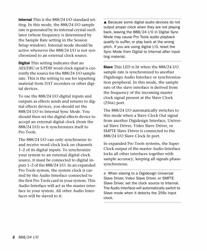
888/24 I/O Back PanelThe 888/24 I/O has the following back panel connectors, moving from left to right:
1. Analog Audio Outputs
These are balanced male XLR connectors for analog audio output connections. All eight output channels are continuously ac-tive. The 888/24 I/O analog outputs feature 24-bit digital-to-analog converters.
2. Analog Audio Inputs
These are balanced female XLR connectors for analog audio input connections. The 888/24 I/O analog inputs feature 24-bit an-alog-to-digital converters. Because input channels 1–8 of the 888/24 I/O are soft-ware selectable in pairs between analog or digital format, analog input to a channel
Back panel of the 888/24 I/O
888/24 I/O
pair is disabled when digital input format is chosen for that channel.
The 888/24 I/O analog audio connectors are balanced XLRs with pin 2 wired hot, (or “+”); pin 3 cold, (or “–”); and pin 1 ground.
3. AES/EBU Digital Outputs 1–8
The 888/24 I/O AES/EBU output jacks are balanced, three conductor, XLR connectors which output a 24-bit digital data stream. Output is continuously active on both the AES/EBU and S/PDIF jacks even when the 888/24 I/O input selector is set to analog.
4. AES/EBU Digital Inputs 1–8
The AES/EBU digital format is used in many professional digital audio devices, in-cluding some DAT recorders. The Inter-face’s AES/EBU input jacks are balanced, three conductor, XLR connectors which ac-cept a full 24-bit digital data stream.
For AES/EBU connections, 110-ohm cables are highly recommended for use in profes-sional installations. For best results, cable lengths should not exceed 30 meters.
Input channels 1–8 of the 888/24 I/O are software-selectable in pairs between analog or digital format. Digital input to a channel pair is disabled when analog input format is chosen for that channel in the Hardware Setup dialog. Input to AES/EBU input chan-nels 1–2 is disabled when S/PDIF digital for-mat is chosen for these inputs in the Pro Tools Session Setup window.
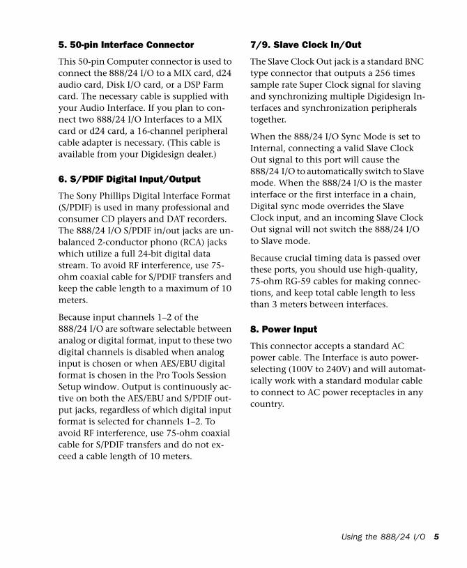
5. 50-pin Interface Connector
This 50-pin Computer connector is used to connect the 888/24 I/O to a MIX card, d24 audio card, Disk I/O card, or a DSP Farm card. The necessary cable is supplied with your Audio Interface. If you plan to con-nect two 888/24 I/O Interfaces to a MIX card or d24 card, a 16-channel peripheral cable adapter is necessary. (This cable is available from your Digidesign dealer.)
6. S/PDIF Digital Input/Output
The Sony Phillips Digital Interface Format (S/PDIF) is used in many professional and consumer CD players and DAT recorders. The 888/24 I/O S/PDIF in/out jacks are un-balanced 2-conductor phono (RCA) jacks which utilize a full 24-bit digital data stream. To avoid RF interference, use 75-ohm coaxial cable for S/PDIF transfers and keep the cable length to a maximum of 10 meters.
Because input channels 1–2 of the 888/24 I/O are software selectable between analog or digital format, input to these two digital channels is disabled when analog input is chosen or when AES/EBU digital format is chosen in the Pro Tools Session Setup window. Output is continuously ac-tive on both the AES/EBU and S/PDIF out-put jacks, regardless of which digital input format is selected for channels 1–2. To avoid RF interference, use 75-ohm coaxial cable for S/PDIF transfers and do not ex-ceed a cable length of 10 meters.
7/9. Slave Clock In/Out
The Slave Clock Out jack is a standard BNC type connector that outputs a 256 times sample rate Super Clock signal for slaving and synchronizing multiple Digidesign In-terfaces and synchronization peripherals together.
When the 888/24 I/O Sync Mode is set to Internal, connecting a valid Slave Clock Out signal to this port will cause the 888/24 I/O to automatically switch to Slave mode. When the 888/24 I/O is the master interface or the first interface in a chain, Digital sync mode overrides the Slave Clock input, and an incoming Slave Clock Out signal will not switch the 888/24 I/O to Slave mode.
Because crucial timing data is passed over these ports, you should use high-quality, 75-ohm RG-59 cables for making connec-tions, and keep total cable length to less than 3 meters between interfaces.
8. Power Input
This connector accepts a standard AC power cable. The Interface is auto power-selecting (100V to 240V) and will automat-ically work with a standard modular cable to connect to AC power receptacles in any country.
Using the 888/24 I/O 5
6
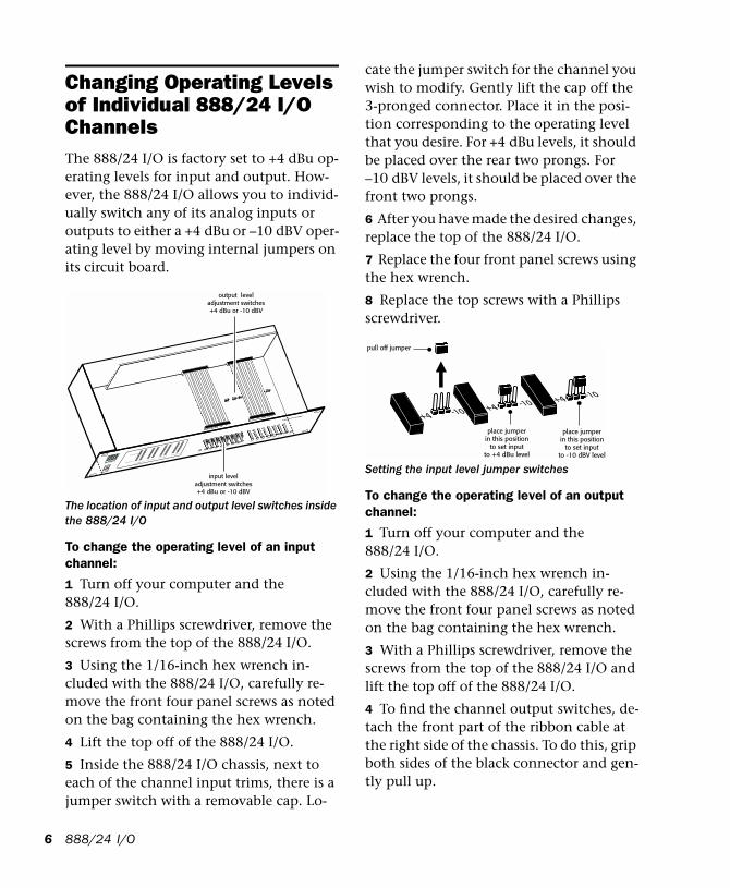
Changing Operating Levels of Individual 888/24 I/O ChannelsThe 888/24 I/O is factory set to +4 dBu op-erating levels for input and output. How-ever, the 888/24 I/O allows you to individ-ually switch any of its analog inputs or outputs to either a +4 dBu or –10 dBV oper-ating level by moving internal jumpers on its circuit board.
To change the operating level of an input channel:
1 Turn off your computer and the 888/24 I/O.
2 With a Phillips screwdriver, remove the screws from the top of the 888/24 I/O.
3 Using the 1/16-inch hex wrench in-cluded with the 888/24 I/O, carefully re-move the front four panel screws as noted on the bag containing the hex wrench.
4 Lift the top off of the 888/24 I/O.
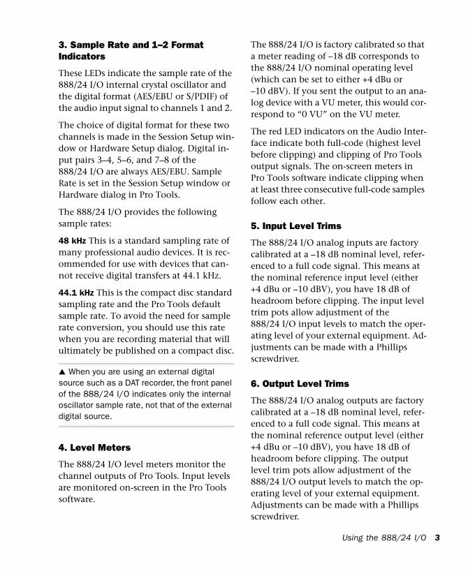
5 Inside the 888/24 I/O chassis, next to each of the channel input trims, there is a jumper switch with a removable cap. Lo-
The location of input and output level switches inside the 888/24 I/O
output leveladjustment switches+4 dBu or -10 dBV
input leveladjustment switches+4 dBu or -10 dBV
888/24 I/O
cate the jumper switch for the channel you wish to modify. Gently lift the cap off the 3-pronged connector. Place it in the posi-tion corresponding to the operating level that you desire. For +4 dBu levels, it should be placed over the rear two prongs. For –10 dBV levels, it should be placed over the front two prongs.
6 After you have made the desired changes, replace the top of the 888/24 I/O.
7 Replace the four front panel screws using the hex wrench.
8 Replace the top screws with a Phillips screwdriver.
To change the operating level of an output channel:
1 Turn off your computer and the 888/24 I/O.
2 Using the 1/16-inch hex wrench in-cluded with the 888/24 I/O, carefully re-move the front four panel screws as noted on the bag containing the hex wrench.
3 With a Phillips screwdriver, remove the screws from the top of the 888/24 I/O and lift the top off of the 888/24 I/O.
4 To find the channel output switches, de-tach the front part of the ribbon cable at the right side of the chassis. To do this, grip both sides of the black connector and gen-tly pull up.
Setting the input level jumper switches
pull off jumper
place jumperin this position
to set inputto +4 dBu level
place jumperin this position
to set inputto -10 dBV level
+4 -10 +4 -10 +4 -10
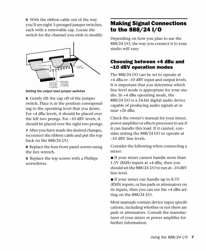
5 With the ribbon cable out of the way you’ll see eight 3-pronged jumper switches, each with a removable cap. Locate the switch for the channel you wish to modify.
6 Gently lift the cap off of the jumper switch. Place it in the position correspond-ing to the operating level that you desire. For +4 dBu levels, it should be placed over the left two prongs. For –10 dBV levels, it should be placed over the right two prongs.
7 After you have made the desired changes, reconnect the ribbon cable and put the top back on the 888/24 I/O.
8 Replace the four front panel screws using the hex wrench.
9 Replace the top screws with a Phillips screwdriver.
Setting the output level jumper switches
detachribbon cable
remove jumper
+4 -10
place jumperin this positionto set output
to +4 dBu level
place jumperin this positionto set output
to -10 dBV level
Making Signal Connections to the 888/24 I/O Depending on how you plan to use the 888/24 I/O, the way you connect it to your studio will vary.
Choosing between +4 dBu and –10 dBV operation modesThe 888/24 I/O can be set to operate at +4 dBu or –10 dBV input and output levels. It is important that you determine which line level mode is appropriate for your stu-dio. In +4 dBu operating mode, the 888/24 I/O is a 24-bit digital audio device capable of producing audio signals at or near +26 dBu.
Check the owner’s manual for your mixer, power amplifier or effects processor to see if it can handle this load. If it cannot, con-sider setting the 888/24 I/O to operate at –10 dBV line levels.
Consider the following when connecting a mixer:
◆ If your mixer cannot handle more than 1.5V (RMS) inputs at +4 dBu, then you should set the 888/24 I/O to run at –10 dBV line level.
◆ If your mixer can handle up to 8.5V (RMS) inputs, or has pads or attenuators on its inputs, then you can use the +4 dBu set-ting on the 888/24 I/O.
Most manuals contain device input specifi-cations, including whether or not there are pads or attenuators. Consult the manufac-turer of your mixer or power amplifier for further information.
Using the 888/24 I/O 7
8
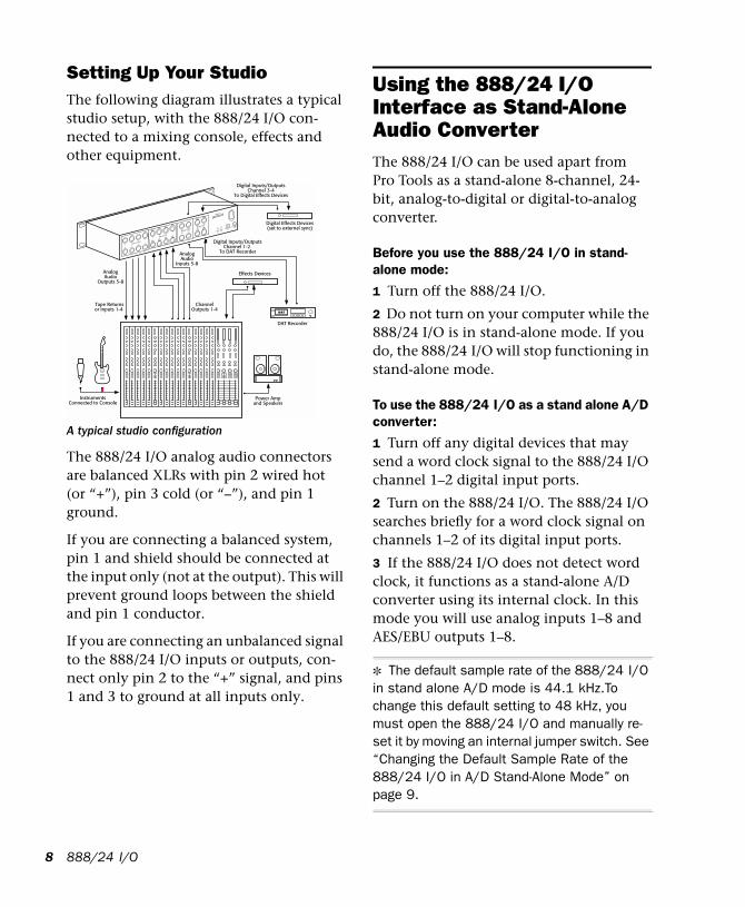
Setting Up Your StudioThe following diagram illustrates a typical studio setup, with the 888/24 I/O con-nected to a mixing console, effects and other equipment.
The 888/24 I/O analog audio connectors are balanced XLRs with pin 2 wired hot (or “+”), pin 3 cold (or “–”), and pin 1 ground.
If you are connecting a balanced system, pin 1 and shield should be connected at the input only (not at the output). This will prevent ground loops between the shield and pin 1 conductor.
If you are connecting an unbalanced signal to the 888/24 I/O inputs or outputs, con-nect only pin 2 to the “+” signal, and pins 1 and 3 to ground at all inputs only.
A typical studio configuration
Power Ampand Speakers
Digital Inputs/OutputsChannel 1-2
To DAT Recorder
Digital Inputs/OutputsChannel 3-4
To Digital Effects Devices
DAT Recorder
InstrumentsConnected to Console
AnalogAudio
Inputs 5-8
AnalogAudio
Outputs 5-8
Effects Devices
Digital Effects Devices(set to external sync)
ChannelOutputs 1-4
Tape Returnsor Inputs 1-4
Computer 1
ANALOG OUTPUT
ANALOG INPUT
AES/EBU OUTPUTAES/EBU INPUT
S/PDIF
IN
S/PDIF
OUT
SLAVE CLOCK
IN
SLAVE CLOCK
OUT
7
8
5
6
3
4
1
2
7
8
5
6
3
4
1
2
5/6
7/8
1/2
3/4
5/6
7/8
1/2
3/4
888/24 I/O
Using the 888/24 I/O Interface as Stand-Alone Audio Converter The 888/24 I/O can be used apart from Pro Tools as a stand-alone 8-channel, 24-bit, analog-to-digital or digital-to-analog converter.
Before you use the 888/24 I/O in stand-alone mode:
1 Turn off the 888/24 I/O.
2 Do not turn on your computer while the 888/24 I/O is in stand-alone mode. If you do, the 888/24 I/O will stop functioning in stand-alone mode.
To use the 888/24 I/O as a stand alone A/D converter:
1 Turn off any digital devices that may send a word clock signal to the 888/24 I/O channel 1–2 digital input ports.
2 Turn on the 888/24 I/O. The 888/24 I/O searches briefly for a word clock signal on channels 1–2 of its digital input ports.
3 If the 888/24 I/O does not detect word clock, it functions as a stand-alone A/D converter using its internal clock. In this mode you will use analog inputs 1–8 and AES/EBU outputs 1–8.
✽ The default sample rate of the 888/24 I/O in stand alone A/D mode is 44.1 kHz.To change this default setting to 48 kHz, you must open the 888/24 I/O and manually re-set it by moving an internal jumper switch. See “Changing the Default Sample Rate of the 888/24 I/O in A/D Stand-Alone Mode” on page 9.
To use the 888/24 I/O as a stand alone D/A converter:
1 Make sure that a digital device providing a word clock signal is connected to AES/EBU inputs 1–2 of the 888/24 I/O and turned on.
2 Turn on the 888/24 I/O. The 888/24 I/O will search for a valid word clock or a word clock signal on channels 1–2 of its digital input ports.
3 When a valid word clock lock is recog-nized, the 888/24 I/O will enter digital sync mode and function as a stand-alone D/A converter using AES/EBU inputs 1–8 and analog outputs 1–8.
The 888/24 I/O D/A sample rate is deter-mined by the sample rate it detects on channels 1–2 of its AES/EBU inputs.
✽ The 888/24 I/O defaults to listening to a digital word clock signal on channels 1–2 of its AES/EBU digital input ports. To use a S/PDIF device as your source of word clock, you must reset this default by opening the 888/24 I/O and moving an internal jumper switch. See “Changing the Default Word Clock Lock Port of the 888/24 I/O in D/A Stand-Alone Mode” on page 10.
To return the 888/24 I/O to Pro Tools-based operation:
◆ Turn on your computer.– or –
◆ If your computer is on, launch Pro Tools.
Changing the Default Sample Rate of the 888/24 I/O in A/D Stand-Alone ModeThe default sample rate of the 888/24 I/O in stand alone A/D mode is 44.1kHz. If you wish to change this default setting to 48 kHz, you must open the 888/24 I/O and manually reset it by moving an internal jumper switch.
To change the default sample rate of the 888/24 I/O in stand alone A/D mode:
1 Make sure that your computer and 888/24 I/O are turned off.
2 With a Phillips screwdriver, remove the screws from the top of the 888/24 I/O.
3 Using the 1/16 inch hex wrench in-cluded with the 888/24 I/O, carefully re-move the front four panel screws as noted on the bag containing the hex wrench.
4 Lift the top off of the 888/24 I/O.
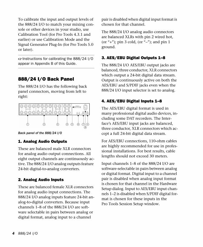
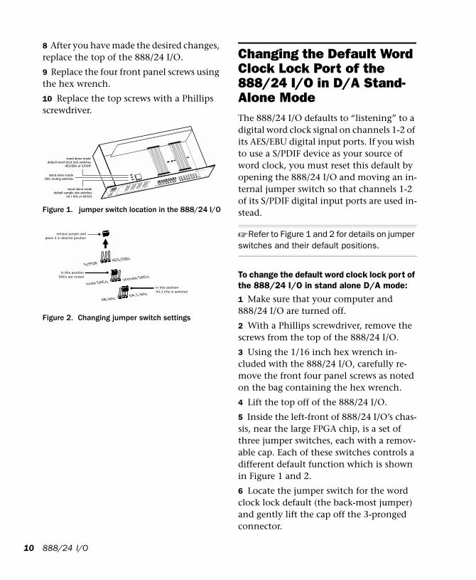
5 Inside the left-front of 888/24 I/O’s chas-sis, near the large FPGA chip, is a set of three jumper switches, each with a remov-able cap. Each of these switches controls a different default function which is shown in Figure 1 and 2.
6 Locate the jumper switch for the default that you wish to modify and gently lift the cap off the 3-pronged connector.
7 Place it in the position corresponding to the value that you desire. For a 44.1 kHz de-fault sample rate, it should be placed over the right two prongs. For a 48 kHz default sample rate, it should be placed over the left two prongs. Refer to Figure 1 and 2 for details.
Using the 888/24 I/O 9
10
8 After you have made the desired changes, replace the top of the 888/24 I/O.
9 Replace the four front panel screws using the hex wrench.
10 Replace the top screws with a Phillips screwdriver.
Figure 1. jumper switch location in the 888/24 I/O
Figure 2. Changing jumper switch settings
stand alone modedefault word clock lock switches
AES/EBU or S/PDIF
stand alone modedefault sample rate switches
44.1 kHz or 48 kHz
stand alone modeDAC muting switches
in this positionDACs are muted
in this position44.1 kHz is selected
44.1 kHz48 kHz
unmute DACs
mute DACs
AES/EBUS/PDIF
remove jumper andplace it in desired position
888/24 I/O
Changing the Default Word Clock Lock Port of the 888/24 I/O in D/A Stand-Alone ModeThe 888/24 I/O defaults to “listening” to a digital word clock signal on channels 1-2 of its AES/EBU digital input ports. If you wish to use a S/PDIF device as your source of word clock, you must reset this default by opening the 888/24 I/O and moving an in-ternal jumper switch so that channels 1-2 of its S/PDIF digital input ports are used in-stead.
☞ Refer to Figure 1 and 2 for details on jumper switches and their default positions.
To change the default word clock lock port of the 888/24 I/O in stand alone D/A mode:
1 Make sure that your computer and 888/24 I/O are turned off.
2 With a Phillips screwdriver, remove the screws from the top of the 888/24 I/O.
3 Using the 1/16 inch hex wrench in-cluded with the 888/24 I/O, carefully re-move the front four panel screws as noted on the bag containing the hex wrench.
4 Lift the top off of the 888/24 I/O.
5 Inside the left-front of 888/24 I/O’s chas-sis, near the large FPGA chip, is a set of three jumper switches, each with a remov-able cap. Each of these switches controls a different default function which is shown in Figure 1 and 2.
6 Locate the jumper switch for the word clock lock default (the back-most jumper) and gently lift the cap off the 3-pronged connector.
7 Place it in the position corresponding to the value that you desire. For an AES/EBU word clock lock port, it should be placed over the right two prongs. For a S/PDIF word clock lock port, it should be placed over the left two prongs. Refer to Figure 1 and 2 for details.
8 After you have made the desired changes, replace the top of the 888/24 I/O.
9 Replace the four front panel screws using the hex wrench.
10 Replace the top screws with a Phillips screwdriver.
Muting the DAC Outputs of the 888/24 I/O in A/D Stand-Alone ModeIn certain cases, you may wish to mute the 888/24 I/O’s D/A converters when in A/D stand-alone mode. This is useful if, for ex-ample, you need to eliminate potential ex-ternal analog feedback through a console.
To do this, you must open the 888/24 I/O and move an internal jumper switch so that the DACs are muted during stand- alone operation.
☞ Refer to Figure 1 and 2 for details on jumper switches and their default positions.
To change the DAC output mute setting of the 888/24 I/O in stand-alone D/A mode:
1 Make sure that your computer and 888/24 I/O are turned off.
2 With a Phillips screwdriver, remove the screws from the top of the 888/24 I/O.
3 Using the 1/16 inch hex wrench in-cluded with the 888/24 I/O, carefully re-move the front four panel screws as noted on the bag containing the hex wrench.
4 Lift the top off of the 888/24 I/O.
5 Inside the left-front of 888/24 I/O’s chas-sis, near the large FPGA chip, is a set of three jumper switches, each with a remov-able cap. Each of these switches controls a different default function as shown in Fig-ure 1 and 2.
6 Locate the jumper switch for the DAC muting default (the middle jumper) and gently lift the cap off the 3-pronged con-nector.
7 Place it in the position corresponding to the value that you desire. To mute the DACs, it should be placed over the left two prongs. To unmute the DACs (as in normal operation), it should be placed over the right two prongs. Refer to Figure 1 and 2 for details.
8 After you have made the desired changes, replace the top of the 888/24 I/O.
9 Replace the four front panel screws using the hex wrench.
10 Replace the top screws with a Phillips screwdriver.
Using the 888/24 I/O 11

12
888/24 I/O
appendix a
Technical Specifications
General
Analog Inputs/Outputs:
■ Actively balanced XLR connectors, outputs internally switchable between +4 dBu and –10 dBV line levels
Analog Level Trimming:
■ Accessible from front panel
Digital I/O AES/EBU:
■ 8 channel; balanced XLR connectors
Digital I/O S/PDIF:
■ 2 channel; coaxial RCA connectors
Sample Rate:
44.1 kHz or 48 kHz, ±10ppm
Clock Reference:
■ Super Clock (256x) sample clock In/Out; BNC connectors; additional clock refer-ences supported via Digidesign's Universal Slave Driver, SMPTE Slave Driver, Video Slave Driver and other optional synchro-nizers
Nominal Operating Level:
■ +4dBu; factory calibrated at –18dB headroom
A/D Specifications
SNR (signal-to-noise ratio):
■ ≥ 113 dB (balanced, A-weighted)
■ ≥ 110 dB (unweighted)
THD:
■ 0.003% –0.01 dB @ 1kHz; 20 Hz-20 kHz (band-limited)
Maximum Input Level:
■ +26dB
Frequency Response:
■ ±1 dB, 20 Hz–20 kHz
Clock jitter:
■ < 40pS RMS 22Hz-22kHz BW
Appendix A: Technical Specifications 13
14
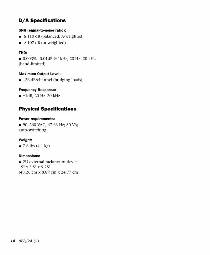
D/A Specifications
SNR (signal-to-noise ratio):
■ ≥ 110 dB (balanced, A-weighted)
■ ≥ 107 dB (unweighted)
THD:
■ 0.003% –0.01dB @ 1kHz; 20 Hz- 20 kHz (band-limited)
Maximum Output Level:
■ +26 dB/channel (bridging loads)
Frequency Response:
■ ±1dB, 20 Hz–20 kHz
Physical Specifications
Power requirements:
■ 90–260 VAC, 47 63 Hz; 30 VA; auto-switching
Weight:
■ 7.6 lbs (4.1 kg)
Dimensions:
■ 2U external rackmount device19" x 3.5" x 9.75" (48.26 cm x 8.89 cm x 24.77 cm)
888/24 I/O
appendix b
Calibrating the 888/24 I/O (Pro Tools 5.0)
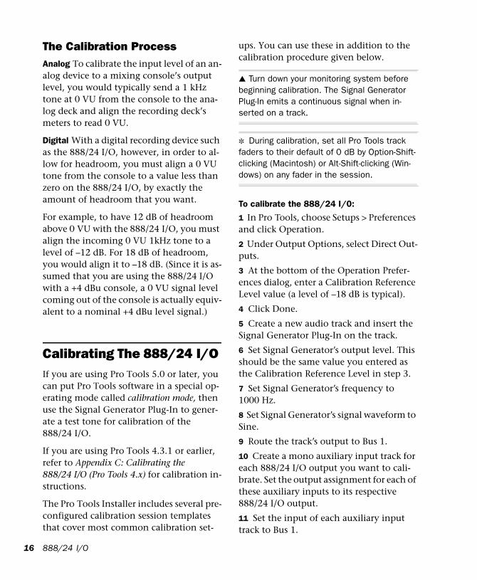
Before you use the 888/24/I/O Audio Inter-face, you may want to calibrate its input and output levels to the level of your mix-ing console.
The 888/24 I/O is factory-calibrated so that its input operating level is set to +4 dB nominal with 18 dB headroom nominal at full code, unity gain, making calibration unnecessary for most professional applica-tions.
If you do need to recalibrate your interface or other components of your studio, you can use the alignment procedure described here.
About CalibrationCalibrating levels on a digital recording de-vice is different from calibrating levels on an analog recording device. Unlike analog devices, most digital devices do not have a standard “0 VU” level setting that corre-sponds to nominal input and output levels. Instead, with an interface such as the 888/24 I/O, the meters are calibrated in decibels below peak (digital clipping) level.
Append
HeadroomThe concept of headroom is slightly differ-ent for analog and digital devices.
Analog Most analog devices allow for a cer-tain amount of headroom above 0 VU. If you send a signal above the 0 VU level to an analog recorder, you still have a margin of headroom, and if tape saturation occurs, it does so fairly gracefully, giving the audio a compressed sound that some find desir-able.
Digital Digital devices, on the other hand, do not allow for signals that exceed the dy-namic range of the input. When a signal exceeds the maximum input level for a dig-ital device, clipping occurs, causing digital distortion, which is harsh and usually un-desirable.
The 888/24 I/O provides an industry stan-dard headroom of 18 dB. The exact value you use will be determined by the amount of headroom available in the rest of your system. For example, if your mixing con-sole has 15 dB of headroom above nominal level, then you may want to calibrate the 888/24 I/O to have 15 dB of headroom.
ix B: Calibrating the 888/24 I/O (Pro Tools 5.0) 15
16
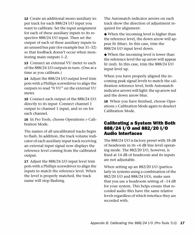
The Calibration ProcessAnalog To calibrate the input level of an an-alog device to a mixing console’s output level, you would typically send a 1 kHz tone at 0 VU from the console to the ana-log deck and align the recording deck’s meters to read 0 VU.
Digital With a digital recording device such as the 888/24 I/O, however, in order to al-low for headroom, you must align a 0 VU tone from the console to a value less than zero on the 888/24 I/O, by exactly the amount of headroom that you want.
For example, to have 12 dB of headroom above 0 VU with the 888/24 I/O, you must align the incoming 0 VU 1kHz tone to a level of –12 dB. For 18 dB of headroom, you would align it to –18 dB. (Since it is as-sumed that you are using the 888/24 I/O with a +4 dBu console, a 0 VU signal level coming out of the console is actually equiv-alent to a nominal +4 dBu level signal.)
Calibrating The 888/24 I/O If you are using Pro Tools 5.0 or later, you can put Pro Tools software in a special op-erating mode called calibration mode, then use the Signal Generator Plug-In to gener-ate a test tone for calibration of the 888/24 I/O.
If you are using Pro Tools 4.3.1 or earlier, refer to Appendix C: Calibrating the 888/24 I/O (Pro Tools 4.x) for calibration in-structions.
The Pro Tools Installer includes several pre-configured calibration session templates that cover most common calibration set-
888/24 I/O
ups. You can use these in addition to the calibration procedure given below.
▲ Turn down your monitoring system before beginning calibration. The Signal Generator Plug-In emits a continuous signal when in-serted on a track.
✽ During calibration, set all Pro Tools track faders to their default of 0 dB by Option-Shift-clicking (Macintosh) or Alt-Shift-clicking (Win-dows) on any fader in the session.
To calibrate the 888/24 I/0:
1 In Pro Tools, choose Setups > Preferences and click Operation.
2 Under Output Options, select Direct Out-puts.
3 At the bottom of the Operation Prefer-ences dialog, enter a Calibration Reference Level value (a level of –18 dB is typical).
4 Click Done.
5 Create a new audio track and insert the Signal Generator Plug-In on the track.
6 Set Signal Generator’s output level. This should be the same value you entered as the Calibration Reference Level in step 3.
7 Set Signal Generator’s frequency to 1000 Hz.
8 Set Signal Generator’s signal waveform to Sine.
9 Route the track’s output to Bus 1.
10 Create a mono auxiliary input track for each 888/24 I/O output you want to cali-brate. Set the output assignment for each of these auxiliary inputs to its respective 888/24 I/O output.
11 Set the input of each auxiliary input track to Bus 1.
12 Create an additional mono auxiliary in-put track for each 888/24 I/O input you want to calibrate. Set the input assignment for each of these auxiliary inputs to its re-spective 888/24 I/O input. Then set the output of each of these auxiliary inputs to an unused bus pair (for example bus 31–32) so that feedback doesn’t occur when mon-itoring main outputs 1–2.
13 Connect an external VU meter to each of the 888/24 I/O outputs in turn. (One at a time as you calibrate.)
14 Adjust the 888/24 I/O output level trim pots with a Phillips screwdriver to align the outputs to read “0 VU” on the external VU meter.
15 Connect each output of the 888/24 I/O directly to its input: Connect channel 1 output to channel 1 input, and so on for each channel.
16 In Pro Tools, choose Operations > Cali-bration Mode.
The names of all uncalibrated tracks begin to flash. In addition, the track volume indi-cator of each auxiliary input track receiving an external input signal now displays the reference level coming from the calibrated output.
17 Adjust the 888/24 I/O input level trim pots with a Phillips screwdriver to align the inputs to match the reference level. When the level is properly matched, the track name will stop flashing.
Append
The Automatch indicator arrows on each track show the direction of adjustment re-quired for alignment:
◆ When the incoming level is higher than the reference level, the down arrow will ap-pear lit (blue). In this case, trim the 888/24 I/O input level down.
◆ When the incoming level is lower than the reference level the up arrow will appear lit (red). In this case, trim the 888/24 I/O input level up.
When you have properly aligned the in-coming peak signal levels to match the cal-ibration reference level, both Automatch indicator arrows will light: the up arrow red and the down arrow blue.
18 When you have finished, choose Oper-ations > Calibration Mode again to deselect Calibration Mode.
Calibrating a System With Both 888/24 I/O and 882/20 I/O Audio InterfacesThe 888/24 I/O is factory preset with 18 dB of headroom in its +4 dB line level operat-ing mode. The 882/20 I/O, however, is fixed at 14 dB of headroom and its inputs are not adjustable.
When setting up an 882/20 I/O (particu-larly in systems using a combination of the 882/20 I/O and 888/24 I/O), make sure that you use a headroom setting of –14 dB for your system. This helps ensure that re-corded audio files have the same relative levels regardless of which interface they are recorded with.
ix B: Calibrating the 888/24 I/O (Pro Tools 5.0) 17

18
888/24 I/O
appendix c
Calibrating the 888/24 I/O (Pro Tools 4.x)
Before you use the 888/24/I/O Audio Inter-face, you may want to calibrate its input and output levels to the level of your mix-ing console.
The 888/24 I/O is factory-calibrated so that its input operating level is set to +4 dB nominal with 18 dB headroom nominal at full code, unity gain, making calibration unnecessary for most professional applica-tions.
If you do need to recalibrate your interface or other components of your studio, you can use the alignment procedure described here.
About CalibrationCalibrating levels on a digital recording de-vice is different from calibrating levels on an analog recording device. Unlike analog devices, most digital devices do not have a standard “0 VU” level setting that corre-sponds to nominal input and output levels. Instead, with an interface such as the 888/24 I/O, the meters are calibrated in decibels below peak (digital clipping) level.
Appen
HeadroomThe concept of headroom is slightly differ-ent for analog and digital devices.
Analog Most analog devices allow for a cer-tain amount of headroom above 0 VU. If you send a signal above the 0 VU level to an analog recorder, you still have a margin of headroom, and if tape saturation occurs, it does so fairly gracefully, giving the audio a compressed sound that some find desir-able.
Digital Digital devices, on the other hand, do not allow for signals that exceed the dy-namic range of the input. When a signal exceeds the maximum input level for a dig-ital device, clipping occurs, causing digital distortion, which is harsh and usually un-desirable.
The 888/24 I/O provides an industry stan-dard headroom of 18 dB. The exact value you use will be determined by the amount of headroom available in the rest of your system. For example, if your mixing con-sole has 15 dB of headroom above nominal level, then you may want to calibrate the 888/24 I/O to have 15 dB of headroom.
dix C: Calibrating the 888/24 I/O (Pro Tools 4.x) 19
20
The Calibration ProcessAnalog To calibrate the input level of an an-alog device to a mixing console’s output level, you would typically send a 1 kHz tone at 0 VU from the console to the ana-log deck and align the recording deck’s meters to read 0 VU.
Digital With a digital recording device such as the 888/24 I/O, however, in order to al-low for headroom, you must align a 0 VU tone from the console to a value less than zero on the 888/24 I/O, by exactly the amount of headroom that you want.
For example, to have 12 dB of headroom above 0 VU with the 888/24 I/O, you must align the incoming 0 VU 1kHz tone to a level of –12 dB. For 18 dB of headroom, you would align it to –18 dB. (Since it is as-sumed that you are using the 888/24 I/O with a +4 dBu console, a 0 VU signal level coming out of the console is actually equiv-alent to a nominal +4 dBu level signal.)
Calibrating The 888/24 I/OIf you are using Pro Tools 4.3.1 or earlier, you can use the Calibration Tool applica-tion (available on your Pro Tools Installer CD-ROM) to calibrate the outputs and in-puts of the 888/24 I//O.
If you are using Pro Tools 5.0 or later, refer to Appendix B: Calibrating the 888/24 I/O (Pro Tools 5.0) for calibration instructions.
888/24 I/O
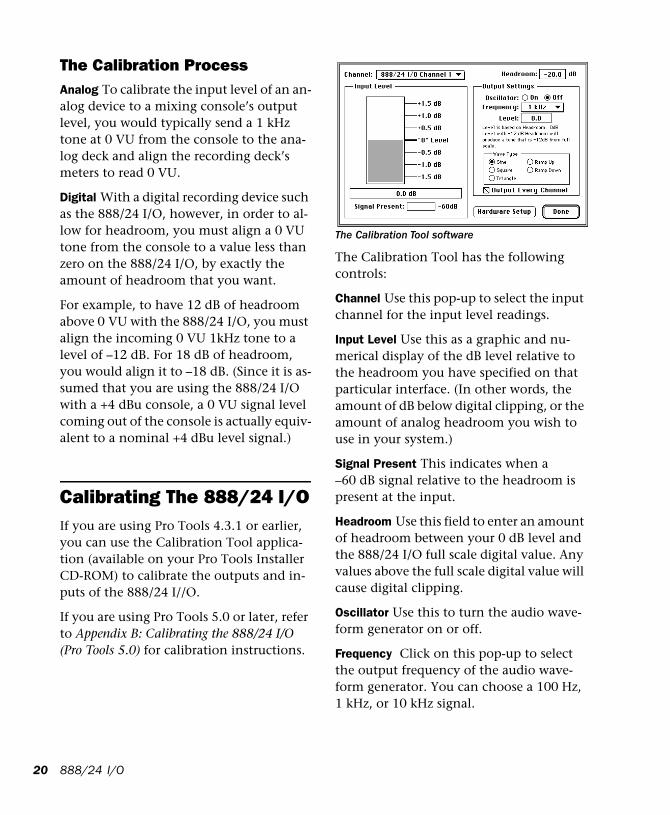
The Calibration Tool software
The Calibration Tool has the following controls:
Channel Use this pop-up to select the input channel for the input level readings.
Input Level Use this as a graphic and nu-merical display of the dB level relative to the headroom you have specified on that particular interface. (In other words, the amount of dB below digital clipping, or the amount of analog headroom you wish to use in your system.)
Signal Present This indicates when a –60 dB signal relative to the headroom is present at the input.
Headroom Use this field to enter an amount of headroom between your 0 dB level and the 888/24 I/O full scale digital value. Any values above the full scale digital value will cause digital clipping.
Oscillator Use this to turn the audio wave-form generator on or off.
Frequency Click on this pop-up to select the output frequency of the audio wave-form generator. You can choose a 100 Hz, 1 kHz, or 10 kHz signal.
Level Use this to select the output level rel-ative to the Headroom for the audio wave-form generator.
Wave Type Use this to select the type of au-dio waveform generated the waveform generator.
Output Every Channel If this option is se-lected and the Oscillator is on, every out-put will generate an audio waveform signal at the selected frequency. If this option is not selected and the Oscillator is on, only the selected output Channel will generate the audio waveform signal. If the Oscillator is off, this option has no effect.
Hardware Setup Use this to choose which Digidesign audio interface and card you wish to adjust using Calibration Tool.
In order to align your system with this soft-ware, you must have one of the following:
◆ A device (such as sine wave or test tone generator) that can send a 1 kHz audio waveform wave into the 888/24 I/O at 0 VU.
– or –
◆ A device (such as a mixing console with accurate VU meters) that can measure the level of a 1kHz audio waveform produced by the 888/24 I/O.
Using an External Tone GeneratorIf you have a sine wave generator that can produce a 0 VU 1 kHz tone, use the follow-ing calibration procedure:
To calibrate the 888/24 I/O with Calibration Tool using an external source:
1 Start the Calibration Tool application.
Appen
2 In the Headroom field, enter the amount of headroom you desire. The default setting for the 888/24 I/O is –18 dB.
3 Send a 1kHz tone into the 888/24 I/O from your external source.
4 In the software, select 888/24 I/O 1 Channel 1 from the Channel pop-up menu. You should get some level in the on-screen level meter.
5 Adjust the 888/24 I/O Channel 1 Input Level trim pot by inserting a screwdriver into the Input Level trim pot and turning it until the Calibration Tool’s on-screen meter reaches 0 VU and the numeric read-out says 0.0 dB. The input is now aligned.
6 Repeat this procedure for each 888/24 I/O input by selecting them from the Channel pop-up menu and adjusting the appropriate front panel Input Level trim pot on the 888/24 I/O.
7 When you have finished aligning the in-puts, connect each output of the 888/24 I/O directly to its input: Connect Channel 1 output to Channel 1 input, and so on.
8 Select 1kHz from the oscillator Fre-quency pop-up menu, and turn the oscilla-tor on by clicking On.
9 Choose 888/24 I/O 1 Channel 1 from the Channel pop-up. Adjust the Output Level trim pots by inserting the Phillips screwdriver into the pot and turning it un-til the on-screen meter reaches 0 VU and the numeric readout says 0.0 dB.
10 Repeat this procedure for each Audio In-terface output.
dix C: Calibrating the 888/24 I/O (Pro Tools 4.x) 21
22
Using a VU meter If you don't have a sine wave generator or another way to send a 1 kHz tone into the 888/24 I/O at 0 VU, a second alternative is to measure the output level of the 888/24 I/O with a VU meter, such as the kind found on a professional-quality mix-ing console. To do this, be sure that the outputs of the 888/24 I/O are connected to the VU meters of the console or other de-vice. (On most consoles these inputs are usually the tape returns, or possibly the line inputs.)
To calibrate the 888/24 I/O with Calibration Tool using an external VU meter:
1 In the Calibration Tool software, select 1 kHz from the Frequency pop-up menu and click the oscillator setting to On.
2 Adjust the 888/24 I/O Output Level trim pots with a Phillips screwdriver to align the outputs to read “0 VU” on your console's meters.
3 After you have done this, connect each output of the 888/24 I/O directly to its in-put: Connect Channel 1 Output to Channel 1 Input, and so on for each chan-nel.
4 To align the inputs, select 888/24 I/O 1 Channel 1 from the Channel pop-up menu. Adjust the 888/24 I/O Input Level trim pot with the screwdriver until the on-screen meter reaches “0 VU”. This input is now aligned.
5 Repeat this procedure for each input.
888/24 I/O