DIFFRACTED - NASA
33
b' 5- k' . I !\ t I ' ? ANNULAR APERTURE 7 \ I DIFFRACTED .EN ERG-Y D I STR I BUT1 0 N I 'FOR AN EXTENDED SOURCE I 1 \ , . i / \ 1 t I 1.1. GOLDBERG A.W. M~CU~LOCH GPO PRICE $ I 6 , a / 1 I ' - CFSTl PRICE(S) $ !' 3, @ Hard copy (HC) Microfiche (MF) G) \ , I ff 653 July65 1 APRIL 1968 , > r GODDARD SPACE FLIGHT CENTER GREENBELT, MARYLAND - :I
Transcript of DIFFRACTED - NASA

b '
5 - k' . I ! \
t I ' ? ANNULAR APERTURE
7
\
I DIFFRACTED .EN ERG-Y D I STR I BUT1 0 N
I
'FOR AN EXTENDED SOURCE I
1
\ , . i
/ \
1 t I
1.1. GOLDBERG A.W. M ~ C U ~ L O C H
GPO PRICE $ I 6 ,
a
/
1 I ' -
CFSTl PRICE(S) $ ! '
3, @ Hard copy (HC)
Microfiche (MF) G) \
, I
ff 653 July65 1
APRIL 1968 ,
> r
GODDARD SPACE FLIGHT CENTER GREENBELT, MARYLAND -
: I

X-622 -68 - 132 PREPRINT
ANNULAR APERTURE DIFFRACTED ENERGY DISTRIBUTION FOR AN EXTENDED SOURCE
I. L. Goldberg A. W. McCulloch
Apri l 1968
Goddard Space Flight Center Greenbel t , Maryland

ANNULAR APERTURE DIFFRACTED ENERGY
DISTRIBUTION FOR AN EXTENDED SOURCE
I. L. Goldberg, A. W. McCulloch

CONTENTS
Page
................................... ABSTRACT V
........................... I. INTRODUCTION.. 1
II. REVIEW O F CIRCULAR APERTURE FRAUNHOFER DIFFRACTION . . . . . . . . . . . . . . . . . . . 3
a. C lea r Aper ture ........................... 3 b. Annular Aper ture .......................... 5
. . . . . 111. EXTENDED SOURCE AND ANNULAR APERTURE 6
................................... APPENDIX 13
REFERENCES ................................. 14
... 111

LIST OF TABLES
Table
1
2
Posi t ions of Minima for Annular Aper tu re Fraunhofer Diffraction for Various Values o f e .q = ~ T D w / X ........................ Annular Aper ture Diffraction f r o m Point Source. One Ai ry Unit = 1.22h/D. E is the Ratio of the Inner to Outer Radii (of the Annular Aperture) . . . Extended Source Diffraction for E = .O, .l. p and B a r e in Airy U n i t s (one A i r y Unit = 1.22 X/D). . . . Extended Source Diffraction for E = .2, .3. p and 6 a r e in Ai ry Units. ..................... Extended Source Diffraction for E = .4, .5. p and B a r e in Airy Units. .....................
LIST O F ILLUSTRATIONS
F igure
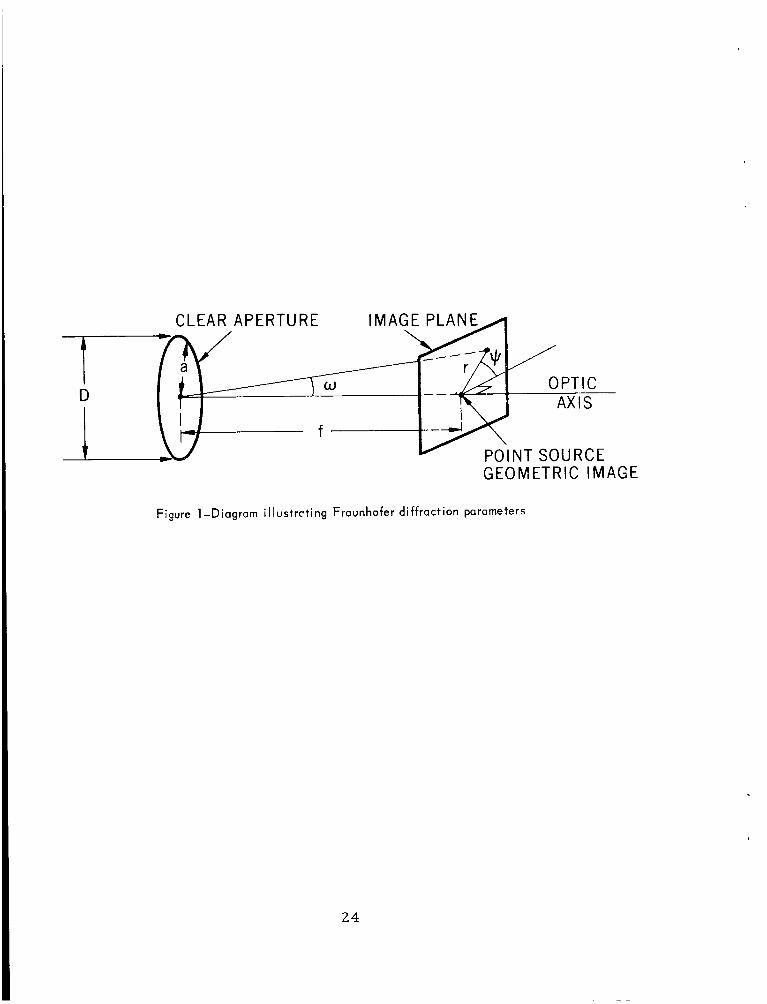
1 Diag ram i l lustrat ing Fraunhofer diffraction p a r a m e t e r s ..........................
2 Relative energy in the first four diffraction r i n g s due to an annular aper ture . . . . . . . . . . . . . . . . .
Page_
15
16
18
20
22
Page
24
25
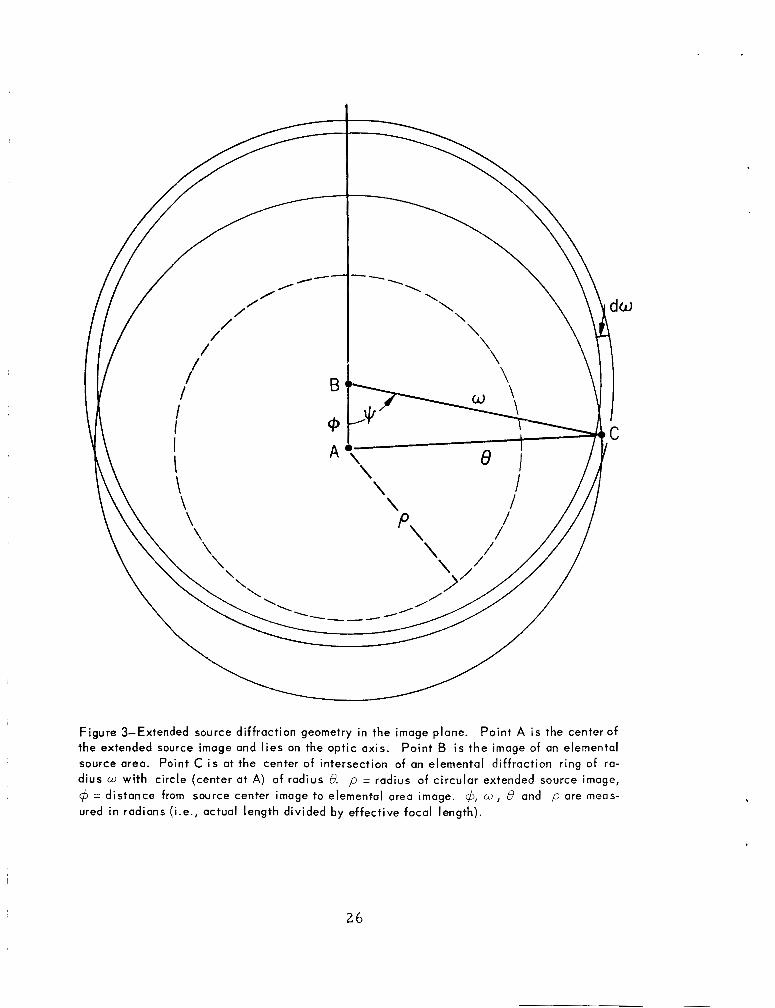
3 Extended source diffraction geometry in the image plane. Point A is the center of the extended source image and l i e s on the optic axis. Point B is the image of a n elemental source a rea . Point C is a t the center of intersect ion of an elemental diffraction r ing of rad ius w with c i rc le (center a t A) of radius e . p = radius of c i r cu la r extended source image, $ = distance from source center image t o e lemental a r e a image. +,w,B and p a r e measured in rad ians (i.e., actual length divided by effective focal length) . . . . . . . . 26
4 Extended source diffraction for E = .4 . . . . . . . . . 27
iv

ANNULAR APERTURE DIFFRACTED ENERGY
DISTRIBUTION FOR AN EXTENDED SOURCE
I. L. Goldberg and A, W. McCulloch
ABSTRACT
The annular ape r tu re diffracted energy within a c i r cu la r a r e a
in the image plane f o r an extended c i r cu la r incoherent source is
obtained by adding the diffraction contributions f r o m a l l the e le -
menta l a r e a s making up the source surface. Each of the source
elemental a r e a s is t r ea t ed as a distant point source so that the
formula for annular ape r tu re Fraunhofer diffraction intensity may
be used. The n e c e s s a r y integration for both the point and extended
source c a s e s w e r e c a r r i e d out numerically by means of the IBM
360 computer and the r e su l t s a r e l i s ted for source angular s i zes
up to five t imes the angular size of the Airy disk. Assuming that
the angular d i ame te r of the c i rcu lar a r e a in the image plane con-
taining 83.870 of the diffracted energy f r o m the extended source is
the effective angular resolution of a scanning optical ins t rument it
is shown that for a cen t r a l obstruction d iameter 4070 of the ape r tu re
d iameter the effective angular resolution is degraded by l e s s than
30% when the instantaneous field of view is increased f r o m 1 to 2
(angular) Ai ry d iameters .
V

ANNULAR APERTURE DIFFRACTED ENERGY
DISTRIBUTION FOR AN EXTENDED SOURCE
I. INTRODUCTION
The diffracted intensity distribution in the image plane for a c l ea r
c i r cu la r ape r tu re and dis tant point source (Fraunhofer diffraction) was
f i r s t der ived by Airy. Lord Rayleigh integrated Ai ry ' s intensity d i s t r i -
bution function to find the ene rgy lying within a c i r cu la r a r e a in the
image plane. When a c i r cu la r obstruction, such as that due to the sec -
ondary m i r r o r in a folded opt ical system, is introduced to f o r m an
annular ape r tu re the diffracted intensity distribution i s a l te red and the
ene rgy distribution (the integral of the intensity distribution) m u s t be
evaluated numerically. F o r extended sources the integration is even
l e s s t rac tab le and a modern high speed computer was used to obtain the
r e s u l t s repor ted here .
Two angularly c lose point sources such a s a double s t a r can be
resolved even when the Ai ry disks (cent ra l bright a r e a of the diffraction
pat tern) assoc ia ted with the point sources overlap. While there is no
p r e c i s e point a t which a double s ta r is ju s t discernible Rayleigh for -
mula ted a quantitative resolution cr i ter ion that is ve ry simple to apply.
Using the assumption that two point sou rces a r e ju s t resolved when the
cen t r a l maximum of the diffraction pat tern of one point fa l ls a t the f i r s t
min imum of the diffract ion pa t te rn of the other point, Rayleigh showed
that
1
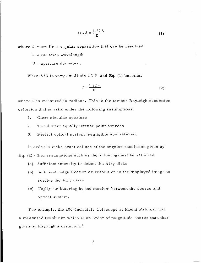
1.22 x s i n e = - D
where 6 = smallest angular separat ion that can be resolved
A = radiation wavelength
D = aperture d i a m e t e r .
When h / D is very s m a l l s in 0 % B and Eq. (1) becomes
1 . 2 2 h B = - D ( 2 )
where B i s measured in radians. This is the famous Rayleigh resolution
c r i t e r ion that i s valid under the following assumptions:
1. Clear c i r cu la r ape r tu re
2.
3.
Two distant equally intense point sou rces
Perfect optical s y s t e m (negligible aber ra t ions) .
In o rde r to make prac t ica l use of the angular resolution given by
Eq. (2) other assurnptions such a s the following m u s t be satisfied:
(a )
(b)
Sufficient intensity to detect the Ai ry disks
Sufficient magnification cr resolution in the displayed image to
resolve the Ai ry disks
Negligible b lur r ing by the medium between the source and
optical sys tern.
( c )
For example, the 200-inch Hale Telescope a t Mount P a l o m a r has
a m e a s u r e d resolution which is an o r d e r of magnitude poore r than that
given by Rayleigh's cr i ter ion.*
2

Because of the overlapping diffraction pat terns a t the Rayleigh
limit, a measu remen t of the total energy f r o m one of the point sou rces
(of, s ay a double star) will include a portion of the energy f r o m the other
point source. Since mos t of the diffracted energy is containedwithin the
Ai ry disk (approximately 84%) two point sou rces a r e somet imes sa id to
be completely resolved when the i r Ai ry disks do not ~ v e r l a p . ~ F o r this
condition the angular resolution is
2.44 X D
ed =- (3)
where 8, is the Ai ry disk angular diameter.
Unfortunately Eq. (2) o r (3) is somet imes used for any "diffraction
l imited" s y s t e m and the above res t r ic t ions a r e s imply ignored, e spe -
c ia l ly assumptions 1 and 2. The effect of using an annular ape r tu re for
observing extended sources will be descr ibed in some detai l in section
111.
11. REVIEW O F CIRCULAR APERTURE
FRAUNHOFER DIFFRACTION
a. Clear Aperture
F o r a c l ea r ape r tu re the normalized diffracted intensity (I,) in
the image plane f r o m a distant point source (plane wave entering the
a p e r t u r e is
I' 2J,(k a s i n w)
I* =[ k a s i n LZ
3
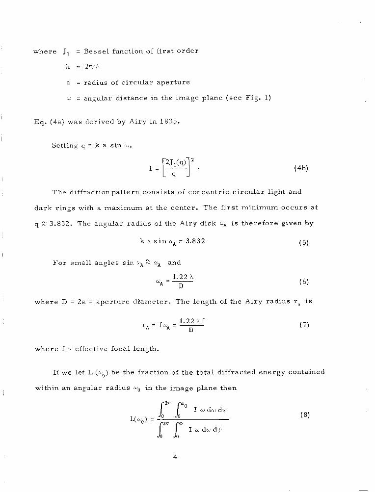
where J, = Besse l function of f i r s t o r d e r
k = 27i/X
a
cc.
= radius of c i r c u l a r ape r tu re
= angular dis tance in the image plane ( s e e Fig . 1)
~
Eq. (4a.) was derived by Ai ry in 1835.
Setting q = k a s in L ,
The diffraction pa t te rn cons is t s of concentr ic c i r c u l a r light and
d a r k r ings with a maximum at the center . The f i r s t min imum o c c u r s at
q 2 3.832. The angular rad ius of the Airy d isk k i is the re fo re given by
( 5) k a s i n L- 3.832
F o r smal l angles s in aA 2 wA and
1.22 A D LcA = -
where D = 2a = ape r tu re cl-jlameter. The length of the Ai ry rad ius ra i s
1.22 X f D
rA = f a A =
where f = effective focal length.
( 7 )
If we let L(&b) be the fract ion of the to ta l diffracted ene rgy contained
within an angular rad ius a. in the image plane then
i26r I w d w d $
12n 6" I w d a d # ym0> =
4

where $J is the polar angle in the image plane. Since I is independent of
$J and q = k a w ( for w small)
now
and s ince
L(qo) = 1 - Jo2(s,> - Jl2(q0) (1 1)
Eq. (11) was der ived by Rayleigh in 1881. F o r qo = 3.832, L(3.832) = .838,
so that approximately 8470 of the diffracted energy is contained within the
Ai ry disk. About 7.270 of the diffracted energy is in the second maximum
ring (first bright r ing surrounding the Ai ry disk). The next two bright
r ings contain 2.8Y0 and 1.570 of the diffracted energy, respectively.
b. Annular ADerture
5 F o r an annular ape r tu re the diffraction intensity distribution is
w h e r e I, = intensity a t the geometrical image of the source
E = ra t io of the radius of the inner c i r c l e ( cen t r a l obstruction)
to that of the outer c i rc le (aper ture) .
The positions of the first four z e r o s (minima) of I for var ious values
of E a r e shown in Table 1. Although the s i ze of the Airy disk dec reases
5

a s E i nc reases , so does the ene rgy contained in the Ai ry disk. As E
i n c r e a s e s from 0 to .4 near ly a l l of the ene rgy los t by the Ai ry disk goes
into the next bright ring. At E = .4, 30% of the diffracted ene rgy is in the
second maximum Xing, while only 58'7'0 r e m a i n s within the Ai ry disk.
Fig. 2 shows how the energy in each of the f irst four bright r ings v a r i e s
with E .
The normalized diffraction energy L is
As shown in the appendix, the denominator of Eq. ( 1 3) is equal to
(1 - €2 ) /2. The numera tor was evaluated numerically. The r e su l t s
a r e given in Table 2.
111. EXTENDED SOURCE AND ANNULAR APERTURE
We shall assurr-e a uniform c i r cu la r incoherent source with angular
radius p and center on the optic axis. The intensity distribution in the
image plane due to an elemental a r e a of solid angle dR in the extended
s o w c e is 5
where 1,d.G = intensity a t the geometr ica l image of the source e le -
men t d o
6

w = angular rad ia l distance in the image plane f r o m the
geometr ic "point source" image ( s e e Fig. 3).
The diffracted ene rgy dPB falling on the c i r cu la r a r e a of angular
radius 8 due to the source element at B ( s e e Fig. 3) is
where C$ is the angular distance of point B f r o m the optic axis. The
relat ionship between # a n d the other p a r a m e t e r s in Eq. (16) is given by
( s e e Fig. 3)
The energy PR on the c i r cu la r a r e a of angular radius B due to all
the e lements in the source a r e a is
where P = angular radius of the geometric source image. Using Eqs. (16)
and (14), Po can be expres sed a s
7

F o r computational purposes it is convenient to le t
q = k a m , B ' = k a d , 4 ' = k a 4 , p' = k a p
4 is now expressed a s
and Eq. (19) becomes
The total diffracted ene rgy PT due to all e lements in the source
a r e a ( $ = 77 for this case) is
16rr2 I, -
(k a)4 (1 -
Since L(1-3') = P e l /PT = f ract ion of the total diffracted ene rgy con-
tained within a c i r c l e of angular radius 0' in the image plane,
8

in o r d e r to evaluate this integral numerical ly , t h ree c a s e s must be
distinguished.
1. 8'2 P'
L, and L2 t L, were numerically integrated by means of the IBM
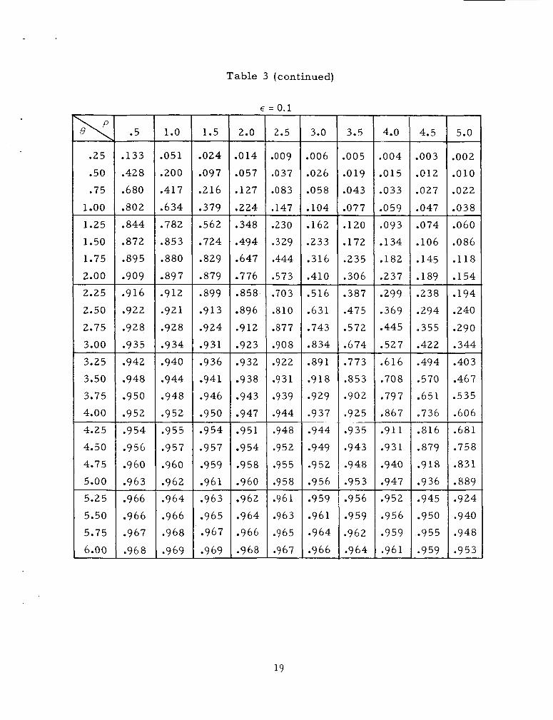
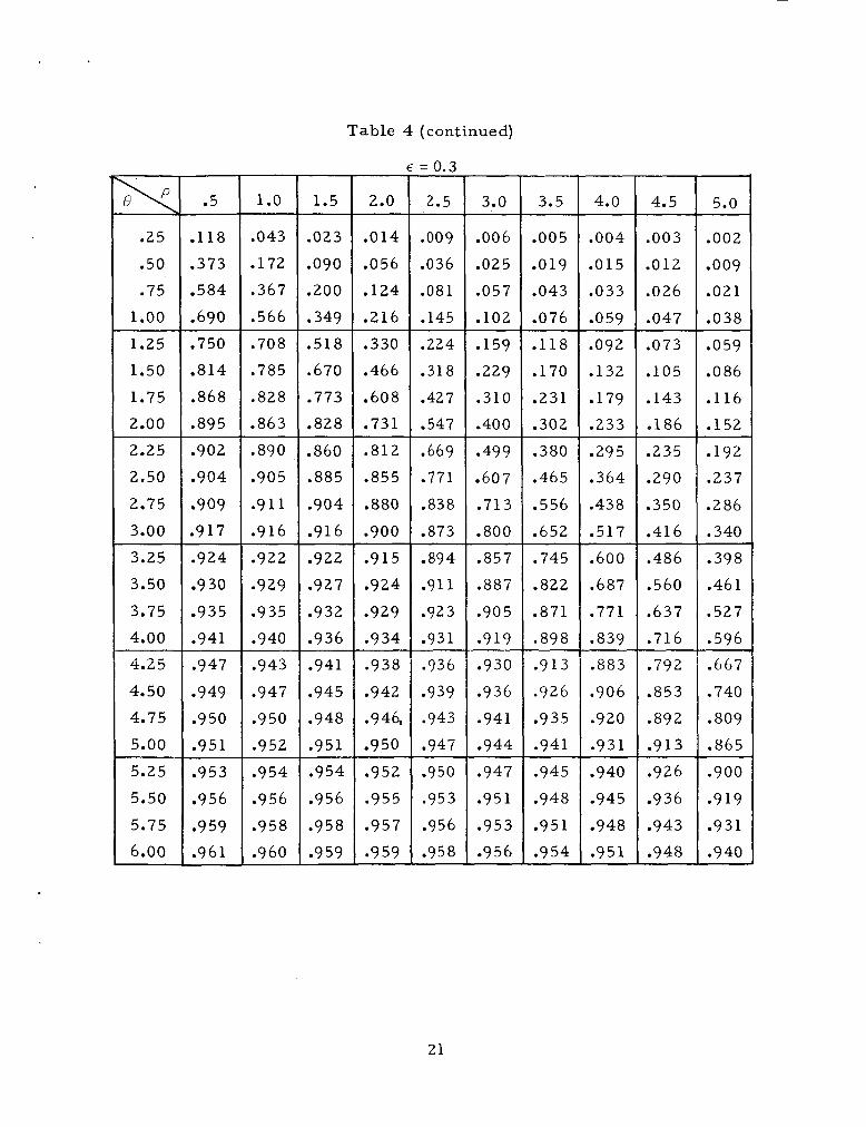
360 computer and the resu l t s a r e given in Tables 3 , 4 and 5. A plot of
L vs 8' for E = .4 is shown in Fig. 4.
9
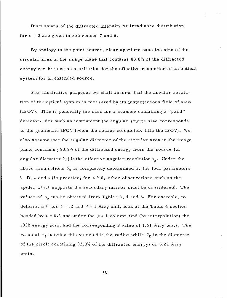
Discussions of the diffracted intensity o r i r r ad iance distribution
for E = 0 a r e given in r e fe rences 7 and 8.
By analogy to the point source , c l e a r a p e r t u r e case the s ize of the
c i r cu la r a r e a in the image plane that contains 83.870 of the diffracted
energy can be used as a c r i t e r ion for the effective resolution of a n optical
s y s t e m for an extended source.
For i l lustrative purposes we shal l a s s u m e that the angular reso lu-
t ion of the optical s y s t e m is measu red by its instantaneous field of view
(IFOV). This is generally the case for a scanner containing a "point"
detect-or. For such an ins t rument the angular source s i ze cor responds
to the geometric IFOV (when the source completely fills the IFOV). We
a l so a s s u m e that the angular diameter of the c i r cu la r a r e a in the image
plane containing 83.870 of the diffracted ene rgy f r o m the source (of
angular diameter 2 ~ ) is the effective angular resolut ion 6,. Under the
above assumptions 6, is completely de te rmined by the four p a r a m e t e r s
A , D, p and E ( in prac t ice , for E > 0 , other obscurat ions such a s the
spider which supports the secondary m i r r o r m u s t be considered). The
values of 0, can be zbtained f r o m Tables 3, 4 and 5. F o r example, to
de te rmine C,for E = .2 and p = 1 Airy unit, look a t the Table 4 section
headed by E = 0.2 and under the p = 1 column find (by interpolation) the
.838 energy point and the corresponding 6 value of 1.61 Ai ry units. The
value of 0, is twice this value ( 0 i s the radius while 8, is the d iameter
of the c i r c l e containing 83.870 of the diffracted energy) o r 3 . 2 2 Airy
units.
10

There for e
3.9x D
8,(.2, 1) = -
where the numbers inside the parenthesis a r e the values of E a n d p
(Airy units) respectively.
Values of 8, for E = 0 and E = 0.4 are given below.
1. E = 0 (Clear Aperture)
3.4h D
OE(O’ 1) = -
5.2X D
B,(O, 2) = -
9.4h 6,(0, 4) = - D
2. E = 0.4
4.9h D
8,(.4, 1) = -
6.3h D
e,(.4, 2) = -
1 ox OE( .4, 4) = - D
11

It is interesting to note that in the region of sma l l source s i zes a s
P i nc reases , 8, does not i nc rease proportionately. This is of par t icu lar
impor tance i n the m e a s u r e m e n t of weak s ignals with ins t ruments for
which the signal-to-noise ra t io (S /N) v a r i e s a s p 2 . F o r example, with
E = 0.4, as P i nc reases f r o m 1 to 2 A i ry units, the S / N in such an ins t ru-
men t increases by a factor of 4 while the effective angular resolution is
degraded by l e s s than 30oJ0. In the region of l a rge values of p , BE i n c r e a s e s
as f a s t a s P .
12

APPENDIX
Evaluation of
Also,
It is shown in books containing in tegra ls of Bessel functions6 that
:. 1, = (1 + €2) (+)- 2 E (;) = - 1 - €2 2
1 3

REFERENCES
1 . R. W. Ditchburn, Light, Second Edition, p. 278.
2. I. S. Bowen, J. Opt. SOC. Am. 42, 795 (1952).
3. F. A. Jenkins and H. E. White, Fundamentals of Optics, Third
Edition, p. 303. I
4. M. Born and E. Wol f , Pr inc ip les of Optics, 1959, 395-397.
5. M. Born and E. W o l f , P r inc ip les of Optics, 1959, p. 415.
6 . G. N. Watson, Theory of Besse l Functions, Second Edition, p. 405.
I 7 . Le W. Smith, J. Opt. SOC. Am. 50, 369 (1960).
8. Lo W. Smith and H. Os terberg , J. Opt. SOC. Am. 51, 412 (1961).
14

Table 1
.1
.2
.3
.4
.5
.6
.7
.8
09
Positions of Minima for Annular Aper tu re Fraunhofer
3.786
3.665
3.50 1
3.323
3.144
2.974
2.814
2.667
2.530
Diffraction for Various Values of ~ . q = .rrDw/h
I Minimum
9 Second
Minimum
7.016
7.128
7.405
7.616
7.501
7.183
6.818
6.458
6.120
5.808
T h i r d Minimum
10.173
9.998
9.703
9.725
10.370
10.965
10.646
10.118
9.594
9.105
Fourth Minimum
13.324
13.573
13.732
13.247
12.683
12.953
14.211
13.766
13.071
12.406
1 5

Table 2
Annular Aper ture Diffraction f r o m Point Source. One Ai ry
Unit = 1.22h/D .t is the Ratio of the Inner to Outer Radii
(of the Annular Aperture) .
w L
E = . 7 t = .9 € = .4 t = .5 i
.033 .030 .027 .O 18 -007
.136 ,123 2 100 .067 ,024
.281 .251 .229 ,132 .047
0.4 .440 .418 ,390 .353 .300 .194 .066
0.1
0.2
0.3
0.5 ,588 ,554 .513 .459 .393 ,240 .078
0.6 .533 .449 .263 .082
0.7 -657 .571 .474 .269
0.8 .583 .479
.584
1 .o 1.1 136
1.2 “720 .650 .580 .414 .158
1.3 .807 .757 .703 .646 .473 .175
1.4 ,877 .836 .760 .712 .520
.184
1.5 .893 .862 .838 .811 .766 .548
.904 .883 .868 .849 .803 .559
.887 .872
.896 .882 .828 ,563 .203
,910 .900 899 .885 .828 .576 ,224
.912 .900 .899 .885 .247
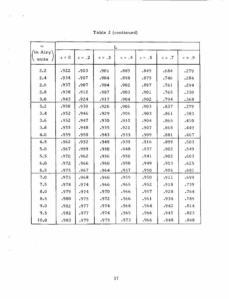
Table 2 (continued)
w
in A i ry ( units ) 2.2
2.4
2.6
2.8
3.0
3.2
3.4
3.6
3.8
4.0
4.5
5.0
5.5
6.0 6.5
7.0
7.5
8.0
8.5
9.0
9.5
10.0
L
E = O € = . 2 € = . 3 € = . 4 E = .5 E = . 7 E = .9
.922 .903 .90 1 .889 .849 .684 .279
.934 .907 .904 .898 .879 .746 .284
.937 .907 .904 .902 .897 .761 .294
.938 .912 .907 .903 .90 1 .765 .330
.943 .924 .917 .904 .902 .794 .368
.950 .939 .926 .906 ,903 .837 .379
.952 .946 e929 .906 ,903 .861 .383
.952 .947 .930 .9lO .904 .865 .410
.955 .948 .935 .921 ,907 .868 .449
,959 ,950 ,943 .933 e909 .881 .467
.962 .952 9949 -939 ,916 e899 .503
.967 .959 .950 .948 .937 .902 e 549
.970 .962 -956 .950 .941 .902 .603
.972 .966 .960 .950 ,949 .90 3 .625
.975 .967 .964 e957 ,950 .906 .681
.975 .968 .966 0959 .950 .9 11 -699
.978 .974 .966 .965 .952 .9 18 .739
.979 .974 .970 .966 .957 .928 .764
,980 .975 .972 .966 ,961 .934 .785
.982 .977 .974 .968 .964 .942 .814
.982 .977 .974 0969 .966 .945 .823
.983 .979 .975 .973 .966 .948 .848
17

Table 3
Extended Source Diffraction for E = . O , .l. p and B are in Airy
.25
.50
.75
1.00
1.25
1.50
1.75
2.00
Units (one Ai ry Unit = 1.22 h /D) .
Relative Diffracted Energy (L)
.135
.435
.693
.818
.859
.882
.902
.915
2.25
2.50
2.75
3.00
3.25
3.50
3.75
4.00
4.25
4.50
4.75
5.00
5.25
5.50
5.75
6.00
.924
.933
.939
.944
.949
.952
.955
.959
.961
.963
.965
,967 .968
.970
.971
.972
1 .o
.052
.204
.425
.644
.794
.864
.891
.907
.920
.930
.936
,942
.947
.951
e955
.958
.960
.963 .965
.966 ~
.968
.970
.971
.972
-- 1.5
-024
.098
.a19
.3 84
.570
.734
.840
.890 -- 0909 .921
.9 32
.939
.944
0949 ,953
.956
-9 59
.962
.964
.966
.968
.969
.970
.972
--
2.0
.014
.057
.128
.227
.352
.500
.655
.785
.868
.906
.921
.931
.9 39
.945
.950
.9 54
.957
.960
.963
.965
.967
.968
,970
.971
--
= o
2.5
.009
.037
.O 84
.149
.232
.332
.449
.580
.711
.819
.886
.917
.930
0939
.945
-951
.9 54
e958
--
.961
.963
.965
.967
-969 -9 70
18
--
3.0
,006
.026
.059
. l o5
.163
.235
.318
.414
.52 2
.637
.751
.843
--
899 .926
.937
.944
.950
.955
.958
.9 6 1
.9 64
.966
.968
.969
3.5
.005
.019
,044
.078
.121
.174
.237
.309
-_
.390
.479
.576
.680
.780
.86C
.9 l0
--
0933
.942
.549
.954
.958
.96i
.964
.966
.968
4.0
.004
“015
.034
.060
-I_-
.093
0 134
.183
.239
.301
-37 1
,448
.531
.620
-714
.803
.874
.9 18
.938
.947
.952
.957
.961
.963
.966
-_I
--
4.5
.003
.012
.027
.048
.074
. lo7
.145
.190
.240
.296
.357
.424
--
.497
.5 74
.656
.741
.822
.886
.924
,942
,950
.956
.960
.963
--
5.0
.002
.010
.021
.039
.060
.087
.118
.154
,195
-241
.29 1
.346
.40 5
.469
.538
.610
.685
.763
.837
,895
.? 30
.946
.953
.958
I-
.5 1.0 1.5 2.0 2.5
,009 ,037 ,083 ,147 ,230 .329 .444 .573 .703 .810 .877 .908 .922 .931
e939 .944 .948 -952 ,955 ,958 .961 .963 .965 .967
3.0
.006
.026
.058
.lo4
.162
.233
.316
.410
.516
.631
.743
.834
.89l ,918
-929 .937 .944
.949
.952
.956
.959
.961 -964
.966
~~
4.5
.003
.012
.027 ,047 .074 .lo6 .145 .189 .238 .294 .355 .422 .494 .570 .651 .736 .816 .879 .918 .936 .945 .950 .955
.959
5.0
.002
.010
.022
.038
.060
.086
.118
.154 ,194 .240 .290 .344 .403 .467 .535 .606 .681 .758 .831 .889 .924 .940 .948 .953
2.00 2.25 2.50 2.75 3.00
.909 .897 .879 .776
.916 .912 .899 .858
.922 .92l .913 .896
.928 .928 ,924 .912
.935 .934 .931 .923 3.25 3.50 3.75 4.00 4.25 4.50 4.75 5.00
.942
.948
.950
.952
.954
.956
.960
.963
Table 3 (continued)
E = 0.1
4.0
,004 .015 .033 .059
3.5
,005 .019 .043
.077
.25 .133 .024 .014
.50 1 .428 1:::; I .097 1.057 .680 .802
.216
.379
.562
.724
.829
.417
.634
.782
.853
.880
.75 1 .oo 1.25 1.50 1.75
,127 .224 .348 .494 .647
.844
.872
.895
.120
.172
.235
.306
.093
. 1 34 e 182 ,237
.387
.475
.572
.674
-299 .369 .445 .527
.932
.9 38
.943
.947
.773
.853
.902
.925
.935
.943
.948 ,953
~___
.936 ,941 .946 .950 .9 54 ,957
09 59 .961
,616 .708 .797 ,867 .9ll .931 .940 .947 .952 .956
.959 ,961
.940
.944
.948 ,952 .955 .957 .960 .962
.951
.954
.9 58
.960 .963 .965 .967
~ .969
.962
.964
.966
.968
.956
99 59 .962 .9 64
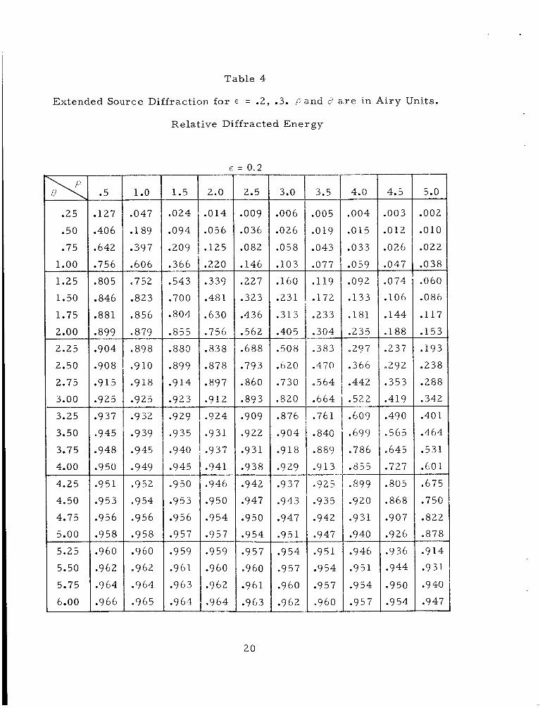
Table 4
Extended Source Diffraction for E = -2, .3. p a n d i a re in A i r y Units.
I, .002
.010
.022
.038
.060
.086
.117
.153
Relat ive Diffracted Energy
.25
.50
.75
1.00
1.25
1.50
1.75
2.00
2.25
2.50
2.75
3.00
3.25
3.50
3.75
4.00
4.25
4.50
4.75
5.00
5.25
5.50
5.75
6.00
E = 0.2
.5
.127
.406
.642
.756
.805
.846
.881
.899
.904
.908
.915
.925
.937
.945
.948
.950
.351
.953
.956
.958
,960
.962
.964
.966
1 .o
.047
. 1 89
.397
.606
.752
.823
.856
.879
.898
.9 10
.918
.925
.9 32
.9 39
.945
0949
.9 52
.954
.956
,958
.960
.962
.964
.965
1.5
.024
,094
.209
.366
.543
.700
.SO4
.855
.880
-899
.914
.923
*929
.935
.940
.945
.950
' ' j 5 3
.956
.957
.9 59
.9 6 1
.963
.9 64
2.0
.014
.056
.125
.220
,337
.48 1
.630
.756
.838
.878
.897
.912
.~
I_-
.924
.931
.937
.941
.946
,950
-954
.957
-959
.960
.962
.964
-_I
-_I
2.5
.009
.036
.082
.146
.227
.323
.436
.562
.688
.793
-860
.893
0909
.922
.931
.938
.942
.947
.950
.954
.957
.960
.961
.963
20
__-
3.0
.006
.026
.058
. l o 3
.160
.231
.313
.40 5
.508
.620
.730
.820
.876
.904
.9 18
-9 29
.937
.943
.947
.951
.9 54
.957
.960
.962
I-
--
3.5
.005
.019
.043
.077
.119
-172
.233
.304
.383
.470
.564
.664
.761
.S40
.889
"9 13
.925
.935
.942
.947
.951
.9 54
.9 57
,960
4.0
.004
,015
.033
.059
--
,092
,133
.181
.235
.2?7
-366
.442
.52.2
.609
,699
-786
,855
_-
.S99
.920
.9 3 1
.940
.946
.951
,954
.957
4.5
.003
.012
.026
,047
.074
. lo6
.144
.188
.237
-292
.353
.419
.490
.565
.645
.727
.805
.868
.907
.926
.9 36
.944
-950
.954
I__.
.193
.238
.288
.342
.40 1
.464
.531
.60 1
.675
.750
.822
.878
.9 14
.9 3 I.
.9 40
.947
.930
.936
.941 E ~ -953 1 .956
.014
.056
.124
.216
.330
.466
.608
.731
.812
.855
.880
.900
.915
.924
.929
.934
.938
.942
.94&
.950
.952
.955
.957
.959
.009
.036
.081
.145
.224
.318
.427
.547
.669
.771
.838
.873
.894
.911
.923 ,931 .936
,939 .943 .947 ,950 .953 .956 .958
.25
.50
.75 1.00 1.25 1.50 1.75 2.00
.118
.373
.584
.690
.750
.814
.868
.895
.Ol9
.043
.076
.118
.170
.231
.302
.015
.033
.059
.092
.132
.179
.233 2.25 2.50 2.75 3.00
,902 .904
8909 .917
3.25 3.50 3.75 4.00 4.25 4.50 4.75 5.00
.924
.930
.935
.941
.947
.949
.950
.951
Table 4 (continued)
E = 0.3 rn .004 .003
1 .o
.043
.172
.367
.566
1.5
.023
.090
.200
.349
5.0
.006
.025
.057
.lo2
.002
.009
.021
.038 ,059 .086 .116 .152
.012
.026
.047 .708 .785 .828 .863
.159
.229
.310
.400
.073
.lo5
.143
.186
.518
.670
.773
.828
.860
.885
.904
.916
.890
.905
.9ll
.916
.380
.465
.556
.652
.295
.364 ,438 .517
.235
.290
.350
.416
9499 .607 .713 .800 .857 .887 .905
0919
.192
.237
.286
.340
.398
.46 1
.527
.596
.667
.740
.809
.865
.900
-
0919 .931 .940
.922
-929 .935 .940
.922
.927
.932
.936
.745
.822
.871
.898
.600
.687
.771
.839
.486
.560
.637
.716 .943 .947 .950 .952
.941
.945
.948 ,951
.883
.906
.920
.931
.9 13
.926
.935
.941
.945
.948
.951
.9 54
.792
.853
.892
.9 13
.926
.936
.943
.948
.954
.956
.958
.960
.940
.945
.948
.951
.954
.956
.958
.9 59
21

.5
.25 .lo5
.50 .329
.75 .512 1.00 .611
1.0
.037
.l52
.330
.517
= 0.4
2.5
,009 .036 .081 ,143 .221 .312 .414 .528 .644 .743 .809 .848 .875 ,096 ,912 .921 .926 .930 .934 .937 .941 .945 -948 .951
3.0
.006
.025
.056
.loo
.157
.226
.305
.393
.487
.589
.690
.775
.832
.865 ..887
.906
.919
.927
.931
.935
.939
.942 -945 .948
.913
.925 .888 .906
Table 5
Extended Source Diffraction for E = .4, .5. p and 0 a r e i n
A i ry U n i t s .
Relative Diffracted Energy
5.0 1.5 4.5
.003
.o 12
.026
.046
2.0
.014
.055
.122
.2 10
.002
.OO?
.02 1
.038
.022
.086
.188
.327 .687 .775 e 848 .882
.655
.737
.792
.841
.318
.446
.581
.698
.778
.826
.857
.883
.903
.9 13
.919 -924 .928 .9 32 .936 .940
--
--
--
.072
.lo4
.141
.184
1.25 1.50 1.75 2.00
.487
.632
.734
.793
.833
.866
.890
.903
.059
.085
.115
150 .190 .234 ,283 .337
.893 ,898
.903
.877
.894
.900
.233
.287
.347
.412
.481
.553
.626
.702
I 2.75 3.00 3.25 3.50 3.75 4.00
.910
.915
.920
.925
.395
.457
.522
.589 1; 5.75
.9 34
.941
.944
.947
.933
.938
.943
.946
.657
.726
.793
.847
.883
.904
.918
.9 30
.775
.834
.874 ,897 .9 i 2 .925 .9 34 .940
.930
.935
-9 39 .943 .947
.949
.951
.953
~~~
0949 .9 50 .9 50 .952
.948
.950
.951
.944
.947
.950
.952 .953

1.5
.021
.080
.172
.298
.444
2.0 2.5 3.0 3.5 4.0 4.5
,013 ,009 .006 .005 .004 ,003
.052 .035 .025 .O 18 .O 14 .O 1 1
.116 ,079 .056 .041 .032 .026
.200 .139 .099 .074 ,057 .045
.301 .214 .154 .115 .089 .071
1 .o
.25
.50
.75
1.00
1.25
1.50
1.75
2.00
2.25
2.50
2.75
3.00
3.25
3.50
3.75
4.00
4.25
4.50
4.75
5.00
5.25
5.50
5.75
6.00
.031
.131
.289
.457
.586
.671
.738
.800
.5
.089
.278
.432
.525
.616
.719
.797
.836
.859
.880
.896
.902
.903
.904
,906
.909
.913
.919 ,927
.934
.938
,942
.946
.949
.845
,870
.883
.894
.90 1
.905
.907
.9i 1
.419
-545
.656
.915
.920
.925
.931
,301
,398 ,503
.937
.941
.944
.947
.221
.297
.381
.470
.565
.660
.742
.799
.835
.862
.885
.581
.681
.746
.166
.224
.292
.366
.445
.528
,614
.698
.769
.Sly
.851
.472
.541
.611
I .682
.794
.837
.867
.883
.916
,921
.925
-930
.934
.938
.942
.945
~
-893
.90 1
.908
.912
.916
.921
.924
.928
.932
.935
.939
.942
.736
.787
.825
.857
.911
.918
.923
.927
.930
,933
.936
.940
~~
.881
.894
.903
.9 10
.902
. 9 l l
,918 ,924
.928
.932
.935
.938
.611
.705
.772
.814
.846
.873
.892
,904
.875
.895
.909
.918
.923
.929
.933
.936
.835
.864
.885
.902
-915
.923
.928
.933
.128
.175
.228
.287
.353
.424
.498
.574
.652
.727
.79 1
. lo2
.139
.182
.230
.283
.342
.405
.751
.809
.849
.864
.893
,909 .921
.928
5.0
.002
.009
.021
.O 37
.058
.084
.114
.149
.188
.232
.280
.332
.389
.450
.513
.578
.643
.708
.771
.823
.860
.883
.900
.915
23
GEOMETRIC IMAGE
Figure 1-Diagram i l lustrct ing Fraunhofer di f f ract ion parameters
2 4

0.9
0.8
0.7
0.6
0.5
L
0.4
0.3
0.2
0.1
0
I ANNULAR
SECOND RING \ r
0 0.1 0.2 0.3 0.4 0.5 0.6 0.7 0.8 0.9 1.0 E
Figure 2-Relative energy in the first four diffraction rings due to an annular aperture
25
I I I I \ \ \ \
4J A
Figure 3-Extended source dif fract ion geometry in the image plane. Po in t A i s the center of the extended source image and l i es on the optic axis. Po in t B i s the image of an elemental source area. Point C i s at the center of intersection of an elemental d i f f ract ion r ing of ro- dius w wi th circle (center a t A) of radius 8. p = radius of circular extended source image, q5 = distance from source center image to elemental area image. g5, w , 6 and p are meas- ured i n radians (i.e., actual length divided by effect ive focal length).
26

1 .o
0.9
0.8
0.7
0.6
L
0.5
0.4
0.3
0.2
0.1
OO
E =0.4 P IS IN A I R Y UNITS
1 A I R Y UNIT = 1.22 x
e ( A I R Y UNITS)
Figure &Extended source diffraction for E = .4
27