Diesel generator set B3.3 series engine€¦ · Frequency regulation 6% Droop for 50 Hz and...
11
power.cummins.com ©2017 Cummins Inc. | S-6282-EN (10/17) Specification sheet Diesel generator set B3.3 series engine 44 kVA - 66 kVA 50 Hz 40 kW - 60 kW 60 Hz Description This Cummins ® commercial generator set is a fully integrated power generation system, providing optimum performance, reliability, and versatility for stationary Standby and Prime Power duty applications. Control system - The PowerStart ® electronic control is standard equipment for 50 Hz products while PowerCommand ® is for 60 Hz products. It provides total genset system integration, including auto remote start/stop, precise frequency and voltage regulation, alarm and status message display. Enclosures - Optional sound attenuated enclosures are available. Warranty - Backed by a comprehensive warranty and worldwide distributor network. Features Cummins medium-duty engine - Rugged 4- cycle industrial diesel delivers reliable power and fast response to load changes. Alternator - Low reactance 2/3 pitch windings; low waveform distortion with non-linear loads, fault clearing short-circuits capability, and class H insulation. Cooling system - Standard Integral set- mounted radiator system, designed and tested for rated ambient temperatures, simplifies facility design requirements for rejected heat. 3-Phase ratings Model Standby rating Prime rating 50 Hz 60 Hz 50 Hz 60 Hz kVA (kW) kW (kVA) kVA (kW) kW (kVA) C44 D5e 44 (35) 40 (32) C55 D5e 55 (44) 50 (40) C66 D5e 66 (53) 60 (48) C40 D6e 40 (50) 36 (45) C50 D6e 50 (63) 45 (57) C60 D6e 60 (75) 55 (68) C44 D5L 44 (35) 40 (32) C55 D5L 55 (44) 50 (40) C66 D5L 66 (53) 60 (48)
Transcript of Diesel generator set B3.3 series engine€¦ · Frequency regulation 6% Droop for 50 Hz and...

power.cummins.com ©2017 Cummins Inc. | S-6282-EN (10/17)
Specification sheet
Diesel generator set B3.3 series engine
44 kVA - 66 kVA 50 Hz
40 kW - 60 kW 60 Hz
Description
This Cummins® commercial generator set is a
fully integrated power generation system, providing optimum performance, reliability, and versatility for stationary Standby and Prime Power duty applications.
Control system - The PowerStart® electronic
control is standard equipment for 50 Hz products while PowerCommand
® is for 60 Hz products. It
provides total genset system integration, including auto remote start/stop, precise frequency and voltage regulation, alarm and status message display.
Enclosures - Optional sound attenuated enclosures are available.
Warranty - Backed by a comprehensive warranty and worldwide distributor network.
Features
Cummins medium-duty engine - Rugged 4-cycle industrial diesel delivers reliable power and fast response to load changes.
Alternator - Low reactance 2/3 pitch windings; low waveform distortion with non-linear loads, fault clearing short-circuits capability, and class H insulation.
Cooling system - Standard Integral set-mounted radiator system, designed and tested for rated ambient temperatures, simplifies facility design requirements for rejected heat.
3-Phase ratings
Model
Standby rating Prime rating
50 Hz 60 Hz 50 Hz 60 Hz
kVA (kW) kW (kVA) kVA (kW) kW (kVA)
C44 D5e 44 (35) 40 (32)
C55 D5e 55 (44) 50 (40)
C66 D5e 66 (53) 60 (48)
C40 D6e 40 (50) 36 (45)
C50 D6e 50 (63) 45 (57)
C60 D6e 60 (75) 55 (68)
C44 D5L 44 (35) 40 (32)
C55 D5L 55 (44) 50 (40)
C66 D5L 66 (53) 60 (48)

power.cummins.com ©2017 Cummins Inc. | S-6282-EN (10/17)
Generator set specifications
Governor regulation class ISO8528 G2
Voltage regulation, no load to full load ± 2.5%
Random voltage variation ± 2.5%
Frequency regulation 6% Droop for 50 Hz and Isochronous for 60 Hz
Random frequency variation ± 0.75%
Radio frequency emissions compliance BS EN61000-6-4/BS EN61000-6-2
Engine specifications
Design 4 cycle, in-line, turbocharged after-cooled
Bore 95 mm (3.75 in.)
Stroke 115 mm (4.53 in.)
Displacement 3.3 L (199 in3)
Cylinder block Cast iron, 4 cylinder
Battery capacity 65 AH
Battery charging alternator 35 Amp
Starting voltage 12 Volt
Fuel system Direct injection
Fuel filter Spin on fuel filters with water separator
Air cleaner type Dry replaceable element with restriction indicator
Lube oil filter type(s) Spin on full flow filter
Standard cooling system* 131 ºF (55 ºC) ambient radiator
*Open genset at 12.7 mm H₂O restriction
Alternator specifications
Design Brushless, single bearing, revolving field
Stator 2/3 pitch winding
Rotor Single bearing, flexible disc coupling
Insulation system Class H
Standard temperature rise Standby 50/60 Hz – 163 ºC/27 ºC ambient
Exciter type Self-excited
Phase rotation A (U), B (V), C (W)
Alternator cooling Direct drive centrifugal fan
AC waveform Total Harmonic Distortion (THDV) No load <1.5%. Non distorting balanced linear load <5%
Telephone Influence Factor (TIF) for 60 Hz < 50% per NEMA MG1-22.43
Telephone Harmonic Factor (THF) for 50 Hz < 2%
Available voltages 50 Hz Line-Line/Line-Neutral 60 Hz Line-Line/Line-Neutral
380/220 400/230 416/240
190/110 200/115 208/120
380/220 400/230 416/240 440/255 480/277
190/110 200/115 208/120 220/127 230/132 240/139
*Note: Some voltages may not be available on all models - consult factory for availability.
Generator set options
Sound attenuated housing Engine coolant heater Heavy duty air cleaner Electronic governing on 50 Hz Mains operated battery charger Industrial grade silencer 4P MCCB Aux contact Earth fault relay
Circuit breaker size Language literature Shunt trip Aux 101 332 liter fuel tank Dual wall, with secondary
containment Remote fuel filling PC 1.2
Extended warranty Alternator heater Lower temp rise alt frame Permanent Magnet Generator
(PMG)
*Note: Some options may not be available on all models - consult factory for availability.
power.cummins.com ©2017 Cummins Inc. | S-6282-EN (10/17)
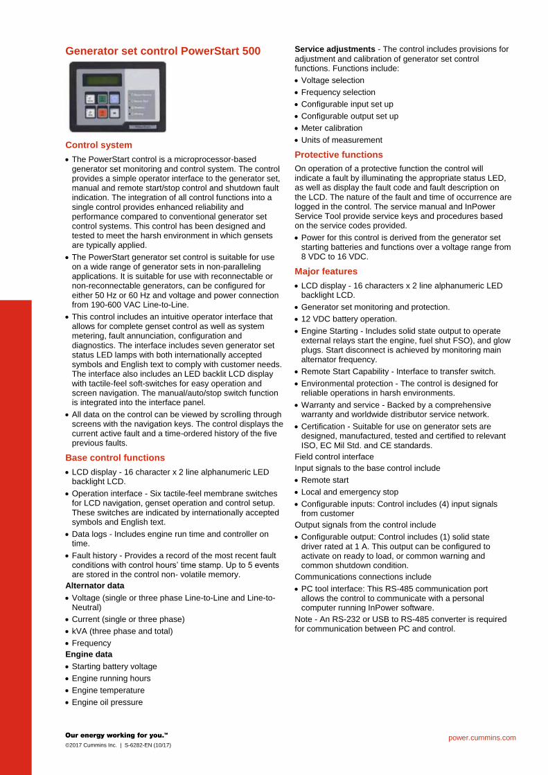
Generator set control PowerStart 500
Control system
The PowerStart control is a microprocessor-based generator set monitoring and control system. The control provides a simple operator interface to the generator set, manual and remote start/stop control and shutdown fault indication. The integration of all control functions into a single control provides enhanced reliability and performance compared to conventional generator set control systems. This control has been designed and tested to meet the harsh environment in which gensets are typically applied.
The PowerStart generator set control is suitable for use on a wide range of generator sets in non-paralleling applications. It is suitable for use with reconnectable or non-reconnectable generators, can be configured for either 50 Hz or 60 Hz and voltage and power connection from 190-600 VAC Line-to-Line.
This control includes an intuitive operator interface that allows for complete genset control as well as system metering, fault annunciation, configuration and diagnostics. The interface includes seven generator set status LED lamps with both internationally accepted symbols and English text to comply with customer needs. The interface also includes an LED backlit LCD display with tactile-feel soft-switches for easy operation and screen navigation. The manual/auto/stop switch function is integrated into the interface panel.
All data on the control can be viewed by scrolling through screens with the navigation keys. The control displays the current active fault and a time-ordered history of the five previous faults.
Base control functions
LCD display - 16 character x 2 line alphanumeric LED backlight LCD.
Operation interface - Six tactile-feel membrane switches for LCD navigation, genset operation and control setup. These switches are indicated by internationally accepted symbols and English text.
Data logs - Includes engine run time and controller on time.
Fault history - Provides a record of the most recent fault conditions with control hours’ time stamp. Up to 5 events are stored in the control non- volatile memory.
Alternator data
Voltage (single or three phase Line-to-Line and Line-to-Neutral)
Current (single or three phase)
kVA (three phase and total)
Frequency
Engine data
Starting battery voltage
Engine running hours
Engine temperature
Engine oil pressure
Service adjustments - The control includes provisions for
adjustment and calibration of generator set control functions. Functions include:
Voltage selection
Frequency selection
Configurable input set up
Configurable output set up
Meter calibration
Units of measurement
Protective functions
On operation of a protective function the control will indicate a fault by illuminating the appropriate status LED, as well as display the fault code and fault description on the LCD. The nature of the fault and time of occurrence are logged in the control. The service manual and InPower Service Tool provide service keys and procedures based on the service codes provided.
Power for this control is derived from the generator set starting batteries and functions over a voltage range from 8 VDC to 16 VDC.
Major features
LCD display - 16 characters x 2 line alphanumeric LED backlight LCD.
Generator set monitoring and protection.
12 VDC battery operation.
Engine Starting - Includes solid state output to operate external relays start the engine, fuel shut FSO), and glow plugs. Start disconnect is achieved by monitoring main alternator frequency.
Remote Start Capability - Interface to transfer switch.
Environmental protection - The control is designed for reliable operations in harsh environments.
Warranty and service - Backed by a comprehensive warranty and worldwide distributor service network.
Certification - Suitable for use on generator sets are designed, manufactured, tested and certified to relevant ISO, EC Mil Std. and CE standards.
Field control interface
Input signals to the base control include
Remote start
Local and emergency stop
Configurable inputs: Control includes (4) input signals from customer
Output signals from the control include
Configurable output: Control includes (1) solid state driver rated at 1 A. This output can be configured to activate on ready to load, or common warning and common shutdown condition.
Communications connections include
PC tool interface: This RS-485 communication port allows the control to communicate with a personal computer running InPower software.
Note - An RS-232 or USB to RS-485 converter is required for communication between PC and control.

For more information contact your local Cummins distributor or visit power.cummins.com
©2017 Cummins Inc. All rights reserved. Cummins is a registered trademark of Cummins Inc. PowerCommand, AmpSentry, InPower and “Our energy working for you.” are trademarks of Cummins Inc. Other company, product, or service names may be trademarks or service marks of others. Specifications are subject to change without notice. S-6282-EN (10/17)
Ratings definitions
Standby:
Applicable for supplying power to varying electrical load for the duration of power interruption of a reliable utility source. Emergency Standby Power (ESP) is in accordance with ISO 8528. Fuel Stop power in accordance with ISO 3046, AS 2789, DIN 6271 and BS 5514.
Prime (Unlimited Running Time):
Applicable for supplying power in lieu of commercially purchased power. Prime power is the maximum power available at a variable load for an unlimited number of hours. A 10% overload capability is available for limited time. (Equivalent to Prime Power in accordance with ISO8528 and Overload Power in accordance with ISO3046, AS2789, and DIN6271). This rating is not applicable to all generator set models.
Base Load (Continuous):
Applicable for supplying power continuously to a constant load up to the full output rating for unlimited hours. No sustained overload capability is available for this rating. Consult authorized distributor for rating. (Equivalent to Continuous Power in accordance with ISO8528, ISO3046, AS2789, and DIN6271). This rating is not applicable to all generator set models.
This outline drawing is to provide representative configuration details for Model series only.
See respective model data sheet for specific model outline drawing number.
Do not use for installation design
Model
Open Enclosed
A B C Dry Wt. A B C Dry Wt.
mm (in.) mm (in.) mm (in.) kg (lbs) mm (in.) mm (in.) mm (in.) kg (lbs)
C44 D5e 2050 (81) 967 (38) 1510 (59) 922 (2033) 2270 (89) 975 (38) 1920 (76) 1236 (2725)
C55 D5e 2050 (81) 967 (38) 1510 (59) 922 (2033) 2270 (89) 975 (38) 1920 (76) 1236 (2725)
C66 D5e 2050 (81) 967 (38) 1510 (59) 1019 (2247) 2270 (89) 975 (38) 1920 (76) 1423 (3137)
C40 D6e 2050 (81) 967 (38) 1510 (59) 922 (2033) 2270 (89) 975 (38) 1920 (76) 1326 (2923)
C50 D6e 2050 (81) 967 (38) 1510 (59) 949 (2092) 2270 (89) 975 (38) 1920 (76) 1353 (2983)
C60 D6e 2050 (81) 967 (38) 1510 (59) 1019 (2247) 2270 (89) 975 (38) 1920 (76) 1423 (3137)
C44 D5L 2050 (81) 967 (38) 1510 (59) 922 (2033) 2270 (89) 975 (38) 1920 (76) 1236 (2725)
C55 D5L 2050 (81) 967 (38) 1510 (59) 922 (2033) 2270 (89) 975 (38) 1920 (76) 1236 (2725)
C66 D5L 2050 (81) 967 (38) 1510 (59) 1019 (2247) 2270 (89) 975 (38) 1920 (76) 1423 (3137)
* Note: Weights represent a set with standard features. See outline drawings for weights of other configurations.
Codes and standards
This generator set is designed in facilities certified to ISO 9001 and manufactured in facilities certified to ISO 9001 or ISO 9002.
The 50 Hz generator sets are available with CE certification.
2000/14/EC All enclosed products are designed to meet or exceed EU noise legislation 2000/14/EC step 2006.
ISO 8528 This generator set has been designed to comply with ISO 8528 regulation.

power.cummins.com ©2017 Cummins Inc. | D-6279-EN (10/17)
Generator set data sheet
Model: C44 D5e (B3.3)
Frequency: 50 Hz
Fuel type: Diesel
Spec sheet: S-6282-EN
Noise data sheet (open): MSP-3025
Airflow data sheet: MCP-2021
Fuel consumption
Standby Prime
kVA (kW) kVA (kW)
Ratings 44 (35) 40 (32)
Load 1/4 1/2 3/4 Full 1/4 1/2 3/4 Full
US gph 1.1 1.5 2.3 2.7 1.0 1.4 2.2 2.7
L/hr 4.0 5.7 8.8 10.4 3.9 5.4 8.4 10.2
Engine Standby rating Prime rating
Engine manufacturer Cummins
Engine model 4BTAA3.3-G14
Configuration In-line; 4 cylinder diesel
Aspiration Turbocharged and after-cooled
Gross engine power output, kWm 62.6 58
BMEP at set rated load, kPa 1538 1428
Bore, mm 95
Stroke, mm 115
Rated speed, rpm 1500
Piston speed, m/s 5.75
Compression ratio 19:1
Lube oil capacity, L 8
Overspeed limit, rpm 1650
Regenerative power, kW N/A
Governor type Mechanical as standard
Starting voltage 12 V DC
Fuel flow
Maximum fuel flow, L/hr 45
Maximum fuel inlet restriction, mm Hg (clean filter) 101.6
Maximum fuel inlet temperature, °C 70
power.cummins.com ©2017 Cummins Inc. | D-6279-EN (10/17)
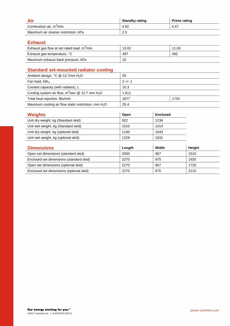
Air Standby rating Prime rating
Combustion air, m3/min 4.92 4.47
Maximum air cleaner restriction, kPa 2.5
Exhaust
Exhaust gas flow at set rated load, m3/min 13.02 11.63
Exhaust gas temperature, °C 497 492
Maximum exhaust back pressure, kPa 10
Standard set-mounted radiator cooling
Ambient design, °C @ 12.7mm H2O 55
Fan load, kWm 2 +/- 1
Coolant capacity (with radiator), L 10.3
Cooling system air flow, m3/sec @ 12.7 mm H2O 1.611
Total heat rejection, Btu/min 1877 1734
Maximum cooling air flow static restriction, mm H2O 25.4
Weights Open Enclosed
Unit dry weight, kg (Standard skid) 922 1236
Unit wet weight, kg (Standard skid) 1010 1414
Unit dry weight, kg (optional skid) 1140 1543
Unit wet weight, kg (optional skid) 1228 1631
Dimensions Length Width Height
Open set dimensions (standard skid) 2050 967 1510
Enclosed set dimensions (standard skid) 2270 975 1920
Open set dimensions (optional skid) 2270 967 1720
Enclosed set dimensions (optional skid) 2270 975 2115

power.cummins.com ©2017 Cummins Inc. | D-6279-EN (10/17)
Genset outline
Open set
Enclosed set
Outlines are for illustrative purposes only. Please refer to the genset outline drawing for an exact representation of this model.
Alternator data Connection
1 Temp rise ºC Duty
2 Alternator Voltage
Wye, 3-phase 163/125 S/P UCI22 4C 380-415
Wye, 3-phase 150/105 S/P UCI22 4D 380-415
For more information contact your local Cummins distributor or visit power.cummins.com
©2017 Cummins Inc. All rights reserved. Cummins is a registered trademark of Cummins Inc. PowerCommand, AmpSentry, InPower and “Our energy working for you.” are trademarks of Cummins Inc. Other company, product, or service names may be trademarks or service marks of others. Specifications are subject to change without notice. D-6279-EN (10/17)
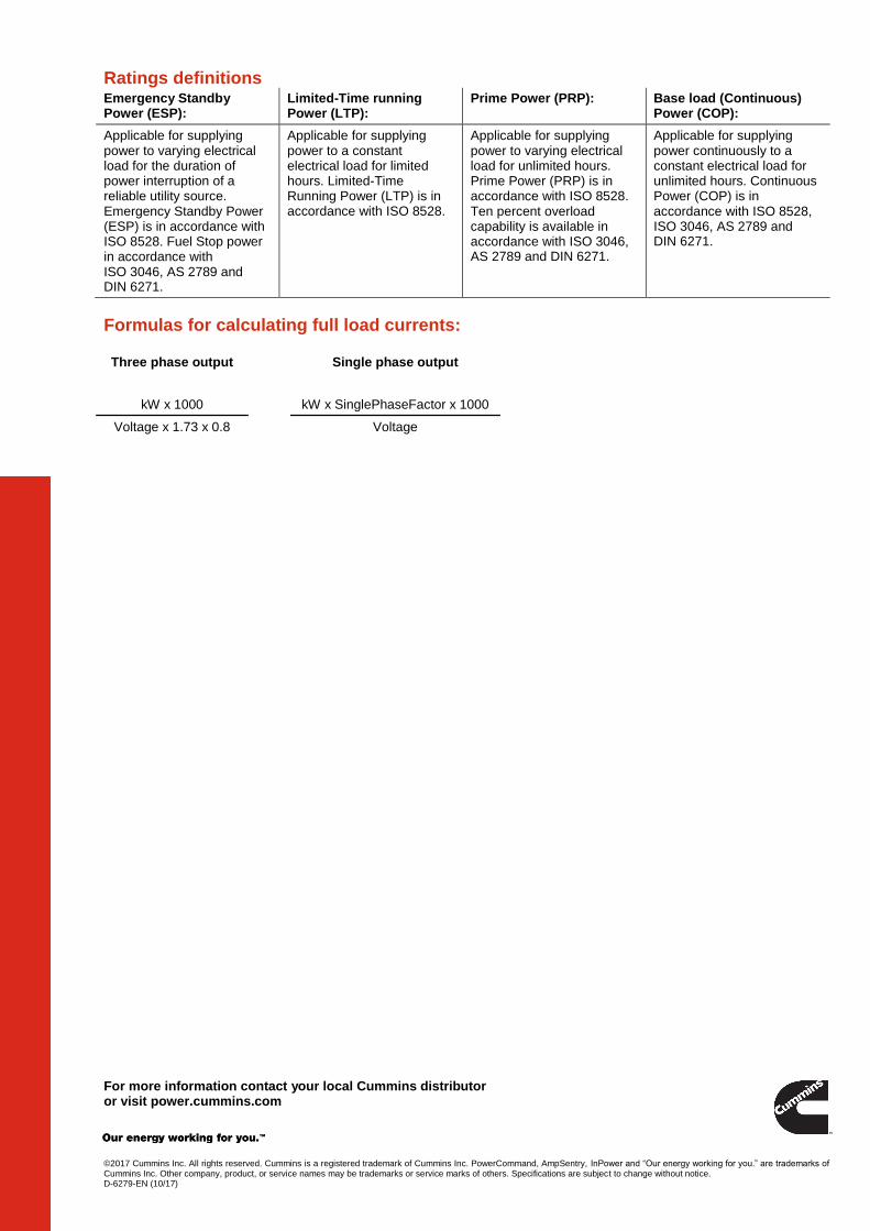
Ratings definitions Emergency Standby Power (ESP):
Limited-Time running Power (LTP):
Prime Power (PRP): Base load (Continuous) Power (COP):
Applicable for supplying power to varying electrical load for the duration of power interruption of a reliable utility source. Emergency Standby Power (ESP) is in accordance with ISO 8528. Fuel Stop power in accordance with ISO 3046, AS 2789 and DIN 6271.
Applicable for supplying power to a constant electrical load for limited hours. Limited-Time Running Power (LTP) is in accordance with ISO 8528.
Applicable for supplying power to varying electrical load for unlimited hours. Prime Power (PRP) is in accordance with ISO 8528. Ten percent overload capability is available in accordance with ISO 3046, AS 2789 and DIN 6271.
Applicable for supplying power continuously to a constant electrical load for unlimited hours. Continuous Power (COP) is in accordance with ISO 8528, ISO 3046, AS 2789 and DIN 6271.
Formulas for calculating full load currents:
Three phase output Single phase output
kW x 1000 kW x SinglePhaseFactor x 1000
Voltage x 1.73 x 0.8 Voltage

4 3 2 1
D
C
B
A
3 2 1
D
C
B
A
4
PTC Creo ParametricR R
CKD
FIRST USED ONFOR INTERPRETATIONOF DIMENSIONING ANDTOLERANCING, SEE
APVD
DWNSIM TOUNLESS OTHERWISE SPECIFIED, ALLDIMENSIONS ARE IN MILLIMETERS
17.50-24.99 +0.30/-0.13
10.00-17.49 +0.25/-0.13
5.00- 9.99 +0.20/-0.10
0.00- 4.99 +0.15/-0.08
DIM
HOLE
ANG TOL
DO NOT SCALE PRINT
SCALE
SITE CODE
CUMMINS POWER GENERATION
SIZEDWG
E
DATE
A054J456THIS DOCUMENT (AND THE INFORMATION SHOWN THEREON) ISCONFIDENTIAL AND PROPRIETARY AND SHALL NOT BE DISCLOSED TO OTHERSIN HARD COPY OR ELECTRONIC FORM, REPRODUCED BY ANY MEANS, ORUSED FOR ANY PURPOSE WITHOUT WRITTEN CONSENT OF CUMMINS INC.
R
NOREVREL NO DATEAPVDCKDDWNREVISION
OF
CAD SHEET
1 2
= =96738.1[ ]
= =84333.2[ ]
89735.3[ ]
100640[ ]
483.519[ ]
483.519[ ]
( )
O/AHEIGHT
192076[ ]1818
72[ ]
227690[ ]
103840.9[ ]
DOOR OPENING
2817110.9[ ]
DOOR OPENING
226589[ ]
O/A WIDTH
97538[ ]
76130[ ]
( )512[ ]
1104[ ]
167365.9[ ]
O/A LENGTH 227089[ ]
51620[ ]
143056[ ]
32413[ ]
38515[ ]
1335.2[ ]
DISPLAYCENTER
130051[ ]
DISPLAY CENTER
186974[ ]
110143[ ]
124349[ ]
30212[ ]
65325.7[ ]
1204.7[ ]
151860[ ]
77831[ ]
1265[ ]
A
83332.8[ ]
34314[ ]
173968[ ]
4X 351.4[ ]
813.2[ ]
B
1676.6[ ]
225689[ ]
ECO-168719 C 1 ADD CE TO EXTERNAL REGULATIONS MR PJ A_PATIL 21MAR17
1X �#�
0.8 .X �#�
0.38 .XX�#�
1.0 1/8 B3.3 INT'LASME Y14.5-2009
04FEB15
A_PATIL
P_JARALI
D_ROKADE
OUTLINE,ENCLOSURE
CIL
A045B515
WEIGHT AND C.G DATA (APPROX)
S/NGENSET MODEL
ENGINE MODELALTERNATOR
FRAMEGENSET DRY WEIGHT (KG)
GENSET WET WEIGHT (KG)
CG LOCATION
DIM A DIM B
1
C40,C44C50,C55C60,C66
G14/G12/G13
UC224C 1313 1401 1257 639
2 UC224D 1326 1414 1263 638
3 UC224E 1353 1441 1275 636
4 UC224F 1373 1461 1283 635
5 UC224G 1423 1511 1302 631.5
SERVICE CONNECTION DETAILS FUEL INLET CONNECTION : �n�10 FUEL RETURN CONNECTION : �n�10 WATER INLET CONNECTION : �n�46 WATER OUTLET CONNECTION : �n�33.5 EXHAUST OUTLET CONNECTION: �n�72 AIR INLET CONNECTION : �n�76.5
NOTES: 1 .DIMENSION SHOWN IN [ ] IN INCHES. 2. THE DIMENSIONS AND C.G DATA ARE FOR REFERANCE ONLY 3. ENCLOSURE MOUNTED EYE BOLTS TO BE USED FOR LIFTING GENSET . 4. AIR CLEANER IS MEDIUM DUTY 5. REMOVE SHIPPING BRACKET BEFORE STARTING THE GENSET. 6. VIEWS SHOWS STANDARD SCOPE BASE SKID 7. FUEL TANK CAPACITY 156 LTR APPROX(12 HRS.FUEL AUTONOMY) 8. CUSTOMER LOAD CABLES TO BE FLEXIBLE TO ALLOW MOVEMENTS OF GENSET ON ANTI VIBRATION MOUNTS 9. FOR ALTERNATOR AND ENGINE COMBINATIONS REFER SHEET 2 10. APPLY DRY TORQUE UNLESS AND OTHERWISE SPECIFIED 11. REFER STD OPRATING MANUAL FOR ANY TECHNICAL PROBLEM 12. THIS OUTLINE IS FOR C40,C44,C50,C55,C60,C66 GENSETS
AIR IN
AIR OUT
RADIATOR END
ALTERNATOR END
AIR IN
AIR OUT
AIR IN
AIR OUT
SINGLE POINT LIFT
3D VIEWSCALE 3/32
PART A054L836 IS SUPPLIED IN KIT AND NEED TO INSTALLED AT THE TIME OF GENSET COMMISIONING
POWER CABLE ENTRY
AIR OUT
AIR OUT
CEPGG 1-01-01-116. This item impacts compliance with these External Regulations:
Regulatory Review and Approval is required prior to changing this item per
ECO-168719 Sheet 1 of 3Part Name: A054J456 Revision: C
Drawing Name: A054J457 Revision: C

4 3 2 1
D
C
B
A
3 2 1
D
C
B
A
4
PTC Creo ParametricR R
CKD
FIRST USED ONFOR INTERPRETATIONOF DIMENSIONING ANDTOLERANCING, SEE
APVD
DWNSIM TOUNLESS OTHERWISE SPECIFIED, ALLDIMENSIONS ARE IN MILLIMETERS
17.50-24.99 +0.30/-0.13
10.00-17.49 +0.25/-0.13
5.00- 9.99 +0.20/-0.10
0.00- 4.99 +0.15/-0.08
DIM
HOLE
ANG TOL
DO NOT SCALE PRINT
SCALE
SITE CODE
CUMMINS POWER GENERATION
SIZEDWG
E
DATE
A054J456THIS DOCUMENT (AND THE INFORMATION SHOWN THEREON) ISCONFIDENTIAL AND PROPRIETARY AND SHALL NOT BE DISCLOSED TO OTHERSIN HARD COPY OR ELECTRONIC FORM, REPRODUCED BY ANY MEANS, ORUSED FOR ANY PURPOSE WITHOUT WRITTEN CONSENT OF CUMMINS INC.
R
NOREVREL NO DATEAPVDCKDDWNREVISION
OF
CAD SHEET
2 2
89735[ ]
1429.856[ ]
317.212.5[ ]
38.61.5[ ]
4X 180.7[ ]
753[ ]
753[ ]
753[ ]
753[ ]156.6
6.2[ ]
2359.3[ ]
98138.6[ ]
2359.3[ ]
226989[ ]
38.61.5[ ]
89735.3[ ]
97438[ ]
B3.3 INT'L ALTERNATOR MATRIX
RATING STANDBY PRIME
GENSET MODEL
STANDBYRATING
kVA (kWe)
STANDBYRATING
kWe (kVA)
PRIME RATING
KVA (kWe)
PRIME RATING
kWe (kVA)ENGINE MODEL VOLTAGE WINDING
STD TEMP RISE OPTIONAL TEMP RISE STD TEMP RISE OPTIONAL TEMP RISE
163/27 150/40 125/40 105/40
C44D5 44 (35) - 40 (32) - 4BTAA3.3G14/G13 190 - 416 V 311UCI224C (46.8)
(A053B575)UCI224D (53)(A053B577)
UCI224C (42.5)(A053B575)
UC224D (45)(A053B577)
C55D5 55 (44) - 50 (40) - 4BTAA3.3G14/G13 190 - 416 V 311UCI224D (55)(A053B577)
UCI224E (61)(A053B579)
UCI224D (50)(A053B577)
UC224E (53)(A053B579)
C66D5 66 (53) - 60 (48) - 4BTAA3.3G14/G13 190 - 416 V 311UCI224F (80)(A053B581)
UCI224G (90.8)(A034E089)
UCI224E (60)(A053B579)
UC224F (65)(A053B581)
C40D6 - 40 (50) - 36 (45) 4BTAA3.3G12
190 - 200 V & 380 - 400 V 14UCI224C (60)(A052U904)
UCI224D (65)(A052U911)
UCI224C (55)(A052U904)
UCI224D (56)(A052U911)
208 - 240 V & 416 - 480 V 311UCI224C (55)(A053B575)
UCI224D (62.5)(A053B577)
UCI224C (50)(A053B575)
UCI224D (52.5)(A053B577)
C50D6 - 50 (62.5) - 45 (57) 4BTAA3.3G12
190 - 200 V & 380 - 400 V 14UCI224D (66.3)
(A052U911)UCI224E (73.8)
(A052V396)UCI224D (62.5)
(A052U911)UCI224E (65)(A052V396)
208 - 240 V & 416 - 480 V 311UCI224D (65)(A053B577)
UCI224E (70)(A053B579)
UCI224D (60)(A053B577)
UCI224E (62.5)(A053B579)
C60D6 - 60 (75) - 55 (68) 4BTAA3.3G12
190 - 200 V & 380 - 400 V 14UCI224E (75)(A052V396)
UCI224F (89.4)(A052V401)
UCI224E (70)(A052V396)
UCI224F (75)(A052V401)
208 - 240 V & 416 - 480 V 311UCI224F (91.9)
(A053B581)UCI224G (98.1)
(A054N520)UCI224F (83.8)
(A053B581)UCI224G (87.5)
(A054N520)
ECO-168719 C - --- MR PJ A_PATIL 21MAR17
1X �#�
0.8 .X �#�
0.38 .XX�#�
1.0 5/32 B3.3 INT'LASME Y14.5-2009
04FEB15
A_PATIL
P_JARALI
D_ROKADE
OUTLINE,ENCLOSURE
CIL
A045B515
FOOT PRINT DETAILS
WITH FOOTSWITH OUT FOOTS
3D VIEWSCALE 1/8
3D VIEWSCALE 1/8
16X M12 WELD NUT
CEPGG 1-01-01-116. This item impacts compliance with these External Regulations:
Regulatory Review and Approval is required prior to changing this item per
ECO-168719 Sheet 2 of 3Part Name: A054J456 Revision: C
Drawing Name: A054J457 Revision: C

Part A054J456 C
Part Specifications :A054J456 C
Description Legacy Name External Regulations Application Status Release Phase Code Security Classification Alternates
OUTLINE,ENCLOSURE A054J456 CE Production Only Production Internal use Only
Name Description Legacy Name
A030B356 SPECIFICATION,MATERIAL CES10903
A054J457 DRAWING,ENGINEERING A054J457
CEPGG 1-01-01-116. This item impacts compliance with these External Regulations:
Regulatory Review and Approval is required prior to changing this item per
ECO-168719 Sheet 3 of 3Part Name: A054J456 Revision: C
Drawing Name: A054J457 Revision: C