Diesel Engines - Bravo Models
90
Diesel Engines - Bravo Models 1996, Mercury Marine 90-860094970 996
Transcript of Diesel Engines - Bravo Models

Die
sel E
ngin
es -
Bra
vo M
odel
s19
96, M
ercu
ry M
arin
e
90-8
6009
4970
99
6
0
CD324
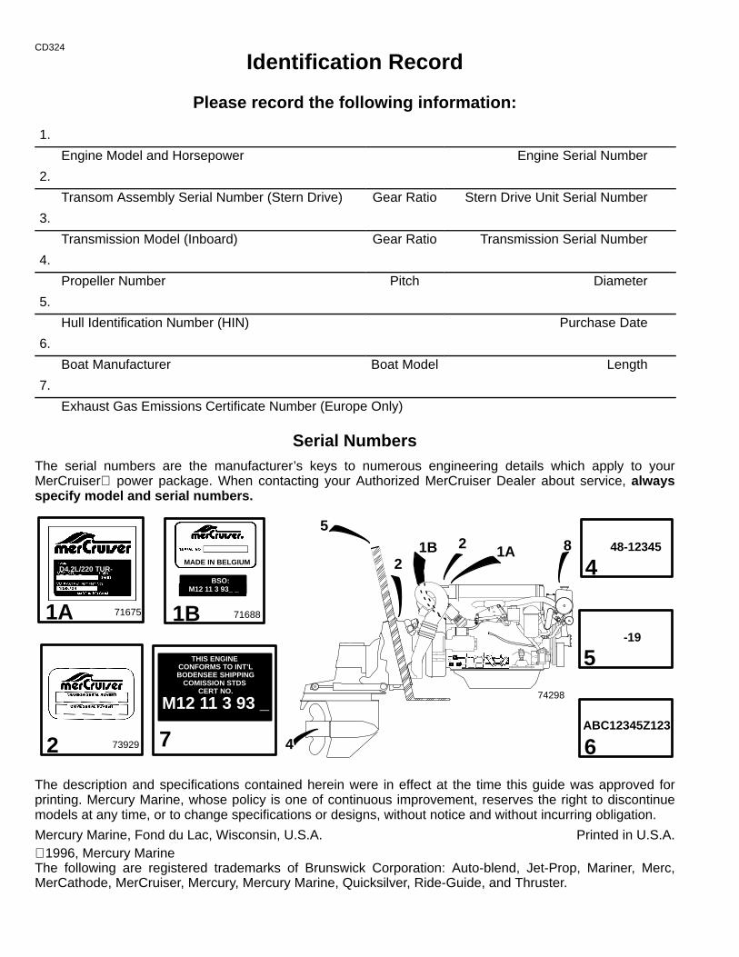
Identification Record
Please record the following information:
1.
Engine Model and Horsepower Engine Serial Number
2.
Transom Assembly Serial Number (Stern Drive) Gear Ratio Stern Drive Unit Serial Number
3.
Transmission Model (Inboard) Gear Ratio Transmission Serial Number
4.
Propeller Number Pitch Diameter
5.
Hull Identification Number (HIN) Purchase Date
6.
Boat Manufacturer Boat Model Length
7.
Exhaust Gas Emissions Certificate Number (Europe Only)
Serial NumbersThe serial numbers are the manufacturer’s keys to numerous engineering details which apply to yourMerCruiser power package. When contacting your Authorized MerCruiser Dealer about service, alwaysspecify model and serial numbers.
ABC12345Z123
-19
48-12345
1A
5
6
2
4
71675
D4.2L/220 TUR-BO AC
2 41A 8
5
7
THIS ENGINE CONFORMS TO INT’LBODENSEE SHIPPING
COMISSION STDS CERT NO.
M12 11 3 93 __
1B
74298
71688
MADE IN BELGIUM
1B
BSO: M12 11 3 93_ _
2 73929
The description and specifications contained herein were in effect at the time this guide was approved forprinting. Mercury Marine, whose policy is one of continuous improvement, reserves the right to discontinuemodels at any time, or to change specifications or designs, without notice and without incurring obligation.
Mercury Marine, Fond du Lac, Wisconsin, U.S.A. Printed in U.S.A. 1996, Mercury MarineThe following are registered trademarks of Brunswick Corporation: Auto-blend, Jet-Prop, Mariner, Merc,MerCathode, MerCruiser, Mercury, Mercury Marine, Quicksilver, Ride-Guide, and Thruster.
1
CD325
TABLE OF CONTENTSPage
WELCOME! 3. . . . . . . . . . . . . . . . . . . . . . . . . . . . . . . . . . . . . . . . . . . . . . . . . . . . . . . . . . . . . . . . . . . . . . . . . . . . . . . . . . Read This Manual Thoroughly 4. . . . . . . . . . . . . . . . . . . . . . . . . . . . . . . . . . . . . . . . . . . . . . . . . . . . . . . . . . . . . . . . . . Lanyard Stop Switch 5. . . . . . . . . . . . . . . . . . . . . . . . . . . . . . . . . . . . . . . . . . . . . . . . . . . . . . . . . . . . . . . . . . . . . . . . . . . Exhaust Emissions 7. . . . . . . . . . . . . . . . . . . . . . . . . . . . . . . . . . . . . . . . . . . . . . . . . . . . . . . . . . . . . . . . . . . . . . . . . . . .
Be Alert To Carbon Monoxide Poisoning 7. . . . . . . . . . . . . . . . . . . . . . . . . . . . . . . . . . . . . . . . . . . . . . . . . . . . . . . Poor Ventilation 7. . . . . . . . . . . . . . . . . . . . . . . . . . . . . . . . . . . . . . . . . . . . . . . . . . . . . . . . . . . . . . . . . . . . . . . . . . . . Good Ventilation 7. . . . . . . . . . . . . . . . . . . . . . . . . . . . . . . . . . . . . . . . . . . . . . . . . . . . . . . . . . . . . . . . . . . . . . . . . . . .
Safe Boating Suggestions 8. . . . . . . . . . . . . . . . . . . . . . . . . . . . . . . . . . . . . . . . . . . . . . . . . . . . . . . . . . . . . . . . . . . . . . Protecting People In The Water 9. . . . . . . . . . . . . . . . . . . . . . . . . . . . . . . . . . . . . . . . . . . . . . . . . . . . . . . . . . . . . . . . .
While You Are Cruising 9. . . . . . . . . . . . . . . . . . . . . . . . . . . . . . . . . . . . . . . . . . . . . . . . . . . . . . . . . . . . . . . . . . . . . . While Boat Is Stationary 9. . . . . . . . . . . . . . . . . . . . . . . . . . . . . . . . . . . . . . . . . . . . . . . . . . . . . . . . . . . . . . . . . . . . .
High-Speed And High-Performance Boat Operation 9. . . . . . . . . . . . . . . . . . . . . . . . . . . . . . . . . . . . . . . . . . . . . . . Conditions Affecting Operation 10. . . . . . . . . . . . . . . . . . . . . . . . . . . . . . . . . . . . . . . . . . . . . . . . . . . . . . . . . . . . . . . . .
Weight Distribution 10. . . . . . . . . . . . . . . . . . . . . . . . . . . . . . . . . . . . . . . . . . . . . . . . . . . . . . . . . . . . . . . . . . . . . . . . . Bottom Of Boat 10. . . . . . . . . . . . . . . . . . . . . . . . . . . . . . . . . . . . . . . . . . . . . . . . . . . . . . . . . . . . . . . . . . . . . . . . . . . . Cavitation 10. . . . . . . . . . . . . . . . . . . . . . . . . . . . . . . . . . . . . . . . . . . . . . . . . . . . . . . . . . . . . . . . . . . . . . . . . . . . . . . . Ventilation 10. . . . . . . . . . . . . . . . . . . . . . . . . . . . . . . . . . . . . . . . . . . . . . . . . . . . . . . . . . . . . . . . . . . . . . . . . . . . . . . . Propeller Selection 11. . . . . . . . . . . . . . . . . . . . . . . . . . . . . . . . . . . . . . . . . . . . . . . . . . . . . . . . . . . . . . . . . . . . . . . . . How Elevation And Climate Affect Performance 12. . . . . . . . . . . . . . . . . . . . . . . . . . . . . . . . . . . . . . . . . . . . . . . Operation And Maintenance 13. . . . . . . . . . . . . . . . . . . . . . . . . . . . . . . . . . . . . . . . . . . . . . . . . . . . . . . . . . . . . . . .
Recommended Operation/Duty Cycle 13. . . . . . . . . . . . . . . . . . . . . . . . . . . . . . . . . . . . . . . . . . . . . . . . . . . . . . Owner/Operator Responsibilities 14. . . . . . . . . . . . . . . . . . . . . . . . . . . . . . . . . . . . . . . . . . . . . . . . . . . . . . . . . . Dealer Responsibilities 14. . . . . . . . . . . . . . . . . . . . . . . . . . . . . . . . . . . . . . . . . . . . . . . . . . . . . . . . . . . . . . . . . .
Freezing Temperature And Cold Weather Operation 15. . . . . . . . . . . . . . . . . . . . . . . . . . . . . . . . . . . . . . . . . . . . Drive Unit Impact Protection 15. . . . . . . . . . . . . . . . . . . . . . . . . . . . . . . . . . . . . . . . . . . . . . . . . . . . . . . . . . . . . . . . Launching and Boat Operation Care 16. . . . . . . . . . . . . . . . . . . . . . . . . . . . . . . . . . . . . . . . . . . . . . . . . . . . . . . . . Attention Required After Submersion 16. . . . . . . . . . . . . . . . . . . . . . . . . . . . . . . . . . . . . . . . . . . . . . . . . . . . . . . . . Trailering Boat 16. . . . . . . . . . . . . . . . . . . . . . . . . . . . . . . . . . . . . . . . . . . . . . . . . . . . . . . . . . . . . . . . . . . . . . . . . . . . Stolen Power Package 16. . . . . . . . . . . . . . . . . . . . . . . . . . . . . . . . . . . . . . . . . . . . . . . . . . . . . . . . . . . . . . . . . . . . . Replacement Service Parts 17. . . . . . . . . . . . . . . . . . . . . . . . . . . . . . . . . . . . . . . . . . . . . . . . . . . . . . . . . . . . . . . . . Do-It-Yourself Maintenance Suggestions 17. . . . . . . . . . . . . . . . . . . . . . . . . . . . . . . . . . . . . . . . . . . . . . . . . . . . . . Diagnosing EDI Problems (If So Equipped) 17. . . . . . . . . . . . . . . . . . . . . . . . . . . . . . . . . . . . . . . . . . . . . . . . . . . Engine Break-In 18. . . . . . . . . . . . . . . . . . . . . . . . . . . . . . . . . . . . . . . . . . . . . . . . . . . . . . . . . . . . . . . . . . . . . . . . . . .
Initial Break-In Procedure 18. . . . . . . . . . . . . . . . . . . . . . . . . . . . . . . . . . . . . . . . . . . . . . . . . . . . . . . . . . . . . . . . 20-Hour Break-In Period 18. . . . . . . . . . . . . . . . . . . . . . . . . . . . . . . . . . . . . . . . . . . . . . . . . . . . . . . . . . . . . . . . .
After Break-In Period 19. . . . . . . . . . . . . . . . . . . . . . . . . . . . . . . . . . . . . . . . . . . . . . . . . . . . . . . . . . . . . . . . . . . . . . . End of First Season Checkup 19. . . . . . . . . . . . . . . . . . . . . . . . . . . . . . . . . . . . . . . . . . . . . . . . . . . . . . . . . . . . . . .
Specifications 20. . . . . . . . . . . . . . . . . . . . . . . . . . . . . . . . . . . . . . . . . . . . . . . . . . . . . . . . . . . . . . . . . . . . . . . . . . . . . . . . Seacock 20. . . . . . . . . . . . . . . . . . . . . . . . . . . . . . . . . . . . . . . . . . . . . . . . . . . . . . . . . . . . . . . . . . . . . . . . . . . . . . . . . . Seawater Strainer 20. . . . . . . . . . . . . . . . . . . . . . . . . . . . . . . . . . . . . . . . . . . . . . . . . . . . . . . . . . . . . . . . . . . . . . . . . Fuel Requirements 20. . . . . . . . . . . . . . . . . . . . . . . . . . . . . . . . . . . . . . . . . . . . . . . . . . . . . . . . . . . . . . . . . . . . . . . . Diesel Fuel In Cold Weather 21. . . . . . . . . . . . . . . . . . . . . . . . . . . . . . . . . . . . . . . . . . . . . . . . . . . . . . . . . . . . . . . . Crankcase Oil 21. . . . . . . . . . . . . . . . . . . . . . . . . . . . . . . . . . . . . . . . . . . . . . . . . . . . . . . . . . . . . . . . . . . . . . . . . . . . . Engine 22. . . . . . . . . . . . . . . . . . . . . . . . . . . . . . . . . . . . . . . . . . . . . . . . . . . . . . . . . . . . . . . . . . . . . . . . . . . . . . . . . . . Capacities 23. . . . . . . . . . . . . . . . . . . . . . . . . . . . . . . . . . . . . . . . . . . . . . . . . . . . . . . . . . . . . . . . . . . . . . . . . . . . . . . . Required Coolant: Quicksilver Premixed Marine Engine Coolant 23. . . . . . . . . . . . . . . . . . . . . . . . . . . . . . . . . Quicksilver Instruments and Instrumentation 25. . . . . . . . . . . . . . . . . . . . . . . . . . . . . . . . . . . . . . . . . . . . . . . . . .
Operation 27. . . . . . . . . . . . . . . . . . . . . . . . . . . . . . . . . . . . . . . . . . . . . . . . . . . . . . . . . . . . . . . . . . . . . . . . . . . . . . . . . . . Electrical System Overload Protection 27. . . . . . . . . . . . . . . . . . . . . . . . . . . . . . . . . . . . . . . . . . . . . . . . . . . . . . . . Mercathode System 27. . . . . . . . . . . . . . . . . . . . . . . . . . . . . . . . . . . . . . . . . . . . . . . . . . . . . . . . . . . . . . . . . . . . . . . . Remote Controls 29. . . . . . . . . . . . . . . . . . . . . . . . . . . . . . . . . . . . . . . . . . . . . . . . . . . . . . . . . . . . . . . . . . . . . . . . . . Power Trim 31. . . . . . . . . . . . . . . . . . . . . . . . . . . . . . . . . . . . . . . . . . . . . . . . . . . . . . . . . . . . . . . . . . . . . . . . . . . . . . . Starting, Shifting and Stopping - D3.6L/180 and D4.2L/220 36. . . . . . . . . . . . . . . . . . . . . . . . . . . . . . . . . . . . . . Operation Chart - D3.6L/180 and D4.2L/220 39. . . . . . . . . . . . . . . . . . . . . . . . . . . . . . . . . . . . . . . . . . . . . . . . . . Starting, Shifting and Stopping - D2.8L D-Tronic and D4.2L D-Tronic 40. . . . . . . . . . . . . . . . . . . . . . . . . . . . . Operation Chart - D2.8L D-Tronic and D4.2L D-Tronic 43. . . . . . . . . . . . . . . . . . . . . . . . . . . . . . . . . . . . . . . . . .
Maintenance 44. . . . . . . . . . . . . . . . . . . . . . . . . . . . . . . . . . . . . . . . . . . . . . . . . . . . . . . . . . . . . . . . . . . . . . . . . . . . . . . . . General Maintenance Information 44. . . . . . . . . . . . . . . . . . . . . . . . . . . . . . . . . . . . . . . . . . . . . . . . . . . . . . . . . . . . Maintenance Aids 44. . . . . . . . . . . . . . . . . . . . . . . . . . . . . . . . . . . . . . . . . . . . . . . . . . . . . . . . . . . . . . . . . . . . . . . . . Maintenance Schedules 45. . . . . . . . . . . . . . . . . . . . . . . . . . . . . . . . . . . . . . . . . . . . . . . . . . . . . . . . . . . . . . . . . . . . Checking Fluid Levels 49. . . . . . . . . . . . . . . . . . . . . . . . . . . . . . . . . . . . . . . . . . . . . . . . . . . . . . . . . . . . . . . . . . . . . .
2
PageCrankcase Oil 49. . . . . . . . . . . . . . . . . . . . . . . . . . . . . . . . . . . . . . . . . . . . . . . . . . . . . . . . . . . . . . . . . . . . . . . . . . Drive Unit Oil 49. . . . . . . . . . . . . . . . . . . . . . . . . . . . . . . . . . . . . . . . . . . . . . . . . . . . . . . . . . . . . . . . . . . . . . . . . . . Power Steering Pump Fluid 49. . . . . . . . . . . . . . . . . . . . . . . . . . . . . . . . . . . . . . . . . . . . . . . . . . . . . . . . . . . . . . Engine Coolant 51. . . . . . . . . . . . . . . . . . . . . . . . . . . . . . . . . . . . . . . . . . . . . . . . . . . . . . . . . . . . . . . . . . . . . . . . . Power Trim Pump Fluid 51. . . . . . . . . . . . . . . . . . . . . . . . . . . . . . . . . . . . . . . . . . . . . . . . . . . . . . . . . . . . . . . . . .
Seawater Pump Impeller 53. . . . . . . . . . . . . . . . . . . . . . . . . . . . . . . . . . . . . . . . . . . . . . . . . . . . . . . . . . . . . . . . . . . Flushing Fuel Tank 53. . . . . . . . . . . . . . . . . . . . . . . . . . . . . . . . . . . . . . . . . . . . . . . . . . . . . . . . . . . . . . . . . . . . . . . . . Propellers (Bravo One and Two) 53. . . . . . . . . . . . . . . . . . . . . . . . . . . . . . . . . . . . . . . . . . . . . . . . . . . . . . . . . . . . . Propellers (Bravo Three) 55. . . . . . . . . . . . . . . . . . . . . . . . . . . . . . . . . . . . . . . . . . . . . . . . . . . . . . . . . . . . . . . . . . . Cleaning Quicksilver Seawater Strainer 57. . . . . . . . . . . . . . . . . . . . . . . . . . . . . . . . . . . . . . . . . . . . . . . . . . . . . . . Flushing Seawater Cooling System 57. . . . . . . . . . . . . . . . . . . . . . . . . . . . . . . . . . . . . . . . . . . . . . . . . . . . . . . . . . Fuel System 59. . . . . . . . . . . . . . . . . . . . . . . . . . . . . . . . . . . . . . . . . . . . . . . . . . . . . . . . . . . . . . . . . . . . . . . . . . . . . .
Fuel Tank 59. . . . . . . . . . . . . . . . . . . . . . . . . . . . . . . . . . . . . . . . . . . . . . . . . . . . . . . . . . . . . . . . . . . . . . . . . . . . . . Hand Pump/Primer 59. . . . . . . . . . . . . . . . . . . . . . . . . . . . . . . . . . . . . . . . . . . . . . . . . . . . . . . . . . . . . . . . . . . . . . Priming Fuel System 59. . . . . . . . . . . . . . . . . . . . . . . . . . . . . . . . . . . . . . . . . . . . . . . . . . . . . . . . . . . . . . . . . . . . Filling Fuel Filter 59. . . . . . . . . . . . . . . . . . . . . . . . . . . . . . . . . . . . . . . . . . . . . . . . . . . . . . . . . . . . . . . . . . . . . . . . Filling (Bleeding) Fuel System 59. . . . . . . . . . . . . . . . . . . . . . . . . . . . . . . . . . . . . . . . . . . . . . . . . . . . . . . . . . . . Draining Water Separating Fuel Filter 59. . . . . . . . . . . . . . . . . . . . . . . . . . . . . . . . . . . . . . . . . . . . . . . . . . . . . . Replacing Water Separating Fuel Filter 61. . . . . . . . . . . . . . . . . . . . . . . . . . . . . . . . . . . . . . . . . . . . . . . . . . . .
Corrosion And Corrosion Protection 61. . . . . . . . . . . . . . . . . . . . . . . . . . . . . . . . . . . . . . . . . . . . . . . . . . . . . . . . . . Internal Components 61. . . . . . . . . . . . . . . . . . . . . . . . . . . . . . . . . . . . . . . . . . . . . . . . . . . . . . . . . . . . . . . . . . . . External Components 63. . . . . . . . . . . . . . . . . . . . . . . . . . . . . . . . . . . . . . . . . . . . . . . . . . . . . . . . . . . . . . . . . . . .
Miscellaneous Maintenance 67. . . . . . . . . . . . . . . . . . . . . . . . . . . . . . . . . . . . . . . . . . . . . . . . . . . . . . . . . . . . . . . . . . . Cold Weather Or Extended Storage 68. . . . . . . . . . . . . . . . . . . . . . . . . . . . . . . . . . . . . . . . . . . . . . . . . . . . . . . . . . . .
Power Package Layup 68. . . . . . . . . . . . . . . . . . . . . . . . . . . . . . . . . . . . . . . . . . . . . . . . . . . . . . . . . . . . . . . . . . . . . Battery Winter Storage 68. . . . . . . . . . . . . . . . . . . . . . . . . . . . . . . . . . . . . . . . . . . . . . . . . . . . . . . . . . . . . . . . . . . . . Power Package Recommissioning 68. . . . . . . . . . . . . . . . . . . . . . . . . . . . . . . . . . . . . . . . . . . . . . . . . . . . . . . . . . .
Troubleshooting 69. . . . . . . . . . . . . . . . . . . . . . . . . . . . . . . . . . . . . . . . . . . . . . . . . . . . . . . . . . . . . . . . . . . . . . . . . . . . . . Starter Motor Will Not Crank Engine, Or Cranks It Very Slowly 69. . . . . . . . . . . . . . . . . . . . . . . . . . . . . . . . . . . Engine Will Not Start, Or Is Hard To Start 69. . . . . . . . . . . . . . . . . . . . . . . . . . . . . . . . . . . . . . . . . . . . . . . . . . . . . Engine Runs Rough, Misses And/Or Backfires 70. . . . . . . . . . . . . . . . . . . . . . . . . . . . . . . . . . . . . . . . . . . . . . . . Poor Performance 70. . . . . . . . . . . . . . . . . . . . . . . . . . . . . . . . . . . . . . . . . . . . . . . . . . . . . . . . . . . . . . . . . . . . . . . . . Excessive Engine Temperature 71. . . . . . . . . . . . . . . . . . . . . . . . . . . . . . . . . . . . . . . . . . . . . . . . . . . . . . . . . . . . . . Insufficient Engine Temperature 71. . . . . . . . . . . . . . . . . . . . . . . . . . . . . . . . . . . . . . . . . . . . . . . . . . . . . . . . . . . . . Low Engine Oil Pressure 72. . . . . . . . . . . . . . . . . . . . . . . . . . . . . . . . . . . . . . . . . . . . . . . . . . . . . . . . . . . . . . . . . . . Battery Will Not Come Up On Charge 72. . . . . . . . . . . . . . . . . . . . . . . . . . . . . . . . . . . . . . . . . . . . . . . . . . . . . . . . Remote Control Operates Hard, Binds, Has Excessive Free-play Or Makes Unusual Sounds 72. . . . . . . . Steering Wheel Turns Hard Or Jerky 73. . . . . . . . . . . . . . . . . . . . . . . . . . . . . . . . . . . . . . . . . . . . . . . . . . . . . . . . . Power Trim Does Not Operate (Electric Motor Does Not Run) 73. . . . . . . . . . . . . . . . . . . . . . . . . . . . . . . . . . . Power Trim Does Not Operate (Electric Motor Runs But Drive Unit Does Not Move) 73. . . . . . . . . . . . . . . .
Warranty Information 74. . . . . . . . . . . . . . . . . . . . . . . . . . . . . . . . . . . . . . . . . . . . . . . . . . . . . . . . . . . . . . . . . . . . . . . . . Owner Warranty Registration 74. . . . . . . . . . . . . . . . . . . . . . . . . . . . . . . . . . . . . . . . . . . . . . . . . . . . . . . . . . . . . . . . International Owner Registration 75. . . . . . . . . . . . . . . . . . . . . . . . . . . . . . . . . . . . . . . . . . . . . . . . . . . . . . . . . . . . .
Warranty Policy 76. . . . . . . . . . . . . . . . . . . . . . . . . . . . . . . . . . . . . . . . . . . . . . . . . . . . . . . . . . . . . . . . . . . . . . . . . . . . . . Mercruiser Diesel Limited Warranty 76. . . . . . . . . . . . . . . . . . . . . . . . . . . . . . . . . . . . . . . . . . . . . . . . . . . . . . . . . . Marine Power International Branch or Distributor Service Offices 78. . . . . . . . . . . . . . . . . . . . . . . . . . . . . . . . . Warranty Coverage 79. . . . . . . . . . . . . . . . . . . . . . . . . . . . . . . . . . . . . . . . . . . . . . . . . . . . . . . . . . . . . . . . . . . . . . . . Transferable Warranty 80. . . . . . . . . . . . . . . . . . . . . . . . . . . . . . . . . . . . . . . . . . . . . . . . . . . . . . . . . . . . . . . . . . . . . . Q-GUARD Product Protection Plan 80. . . . . . . . . . . . . . . . . . . . . . . . . . . . . . . . . . . . . . . . . . . . . . . . . . . . . . . . . .
Owner Service Assistance 81. . . . . . . . . . . . . . . . . . . . . . . . . . . . . . . . . . . . . . . . . . . . . . . . . . . . . . . . . . . . . . . . . . . . . Local Repair Service 81. . . . . . . . . . . . . . . . . . . . . . . . . . . . . . . . . . . . . . . . . . . . . . . . . . . . . . . . . . . . . . . . . . . . . . . Service Away From Home 81. . . . . . . . . . . . . . . . . . . . . . . . . . . . . . . . . . . . . . . . . . . . . . . . . . . . . . . . . . . . . . . . . . Parts And Accessories Inquiries 81. . . . . . . . . . . . . . . . . . . . . . . . . . . . . . . . . . . . . . . . . . . . . . . . . . . . . . . . . . . . . Resolving A Problem 81. . . . . . . . . . . . . . . . . . . . . . . . . . . . . . . . . . . . . . . . . . . . . . . . . . . . . . . . . . . . . . . . . . . . . . . Mercury Marine Service Offices 82. . . . . . . . . . . . . . . . . . . . . . . . . . . . . . . . . . . . . . . . . . . . . . . . . . . . . . . . . . . . .
Customer Service Literature 82. . . . . . . . . . . . . . . . . . . . . . . . . . . . . . . . . . . . . . . . . . . . . . . . . . . . . . . . . . . . . . . . . . . English Language 83. . . . . . . . . . . . . . . . . . . . . . . . . . . . . . . . . . . . . . . . . . . . . . . . . . . . . . . . . . . . . . . . . . . . . . . . . Other Languages 83. . . . . . . . . . . . . . . . . . . . . . . . . . . . . . . . . . . . . . . . . . . . . . . . . . . . . . . . . . . . . . . . . . . . . . . . . .
Literature Order Form 85. . . . . . . . . . . . . . . . . . . . . . . . . . . . . . . . . . . . . . . . . . . . . . . . . . . . . . . . . . . . . . . . . . . . . . . . .
3
CA165
Welcome!
You have selected one of the finest marine power packages available. It incorporates numerous design featuresto assure operating ease and durability.
With proper care and maintenance, you will thoroughly enjoy using this product for many boating seasons. Toensure maximum performance and carefree use, we ask that you thoroughly read this manual.
The Operation and Maintenance Manual contains specific instructions for using and maintaining your product.We suggest that this manual remain with the product for ready reference whenever you are on the water.
Thank you for purchasing one of our MerCruiser products. We sincerely hope your boating will be pleasant!
CONSUMER AFFAIRS DEPARTMENT
CA466
IMPORTANT: This manual contains basic Operation and Maintenance information for your MerCruiserpower package. If you desire to perform some of the maintenance items on your own, you should obtaina copy of the “Maintenance Procedures” Manual for your particular power package. Information forobtaining this manual is located at the back of this manual.
4
CD326
Read This Manual ThoroughlyIF YOU DON’T UNDERSTAND ANY PORTION, CONTACT YOUR DEALER FOR A DEMONSTRATIONOF ACTUAL STARTING AND OPERATING PROCEDURES.
NOTICEThroughout this publication, and on your power package WARNINGS and CAUTIONS, accompanied by the In-ternational HAZARD Symbol ! , may be used to alert the installer/user to special instructions concerning a partic-ular service or operation that may be hazardous if performed incorrectly or carelessly. Observe them carefully.
These “Safety Alerts” alone cannot eliminate the hazards that they signal. Strict compliance with these specialinstructions while performing the service, plus “common sense” operation, are major accident prevention mea-sures.
! WARNINGWARNING - Hazards or unsafe practices which could result in severe personal injury or death.
! CAUTIONCAUTION - Hazards or unsafe practices which could result in minor personal injury or product or proper-ty damage.
IMPORTANT: Indicates information or instructions that are necessary for proper operation and/or main-tenance.
! WARNINGThe operator (driver) is responsible for the correct and safe operation of the boat, the equipment aboardand the safety of all occupants aboard. We strongly recommend that the operator read this Operationand Maintenance Manual and thoroughly understand the operational instructions for the power packageand all related accessories before the boat is used.We strongly recommend that other occupants be instructed on proper starting and operation proce-dures so they will be prepared should they be required to operate the power package and boat in anemergency.
! WARNINGThe use of accessories not manufactured or sold by Mercury Marine is not recommended for use withyour MerCruiser unit. If your MerCruiser unit is equipped with an accessory not manufactured by Mercu-ry Marine, be sure to read the Operation and Maintenance Manual for the accessory before operation.If you haven’t been supplied with such a manual, contact your dealer or the manufacturer of the accesso-ry to secure the applicable manual.
! WARNINGElectrical system components on this engine are not external ignition protected. DO NOT STORE ORUTILIZE GASOLINE ON BOATS EQUIPPED WITH THESE ENGINES, UNLESS PROVISIONS HAVE BEENMADE TO EXCLUDE GASOLINE VAPORS FROM ENGINE COMPARTMENT (REF: 33 CFR). Failure tocomply could result in fire, explosion and/or severe personal injury.
5
CA475
Lanyard Stop Switch
74608
2 1
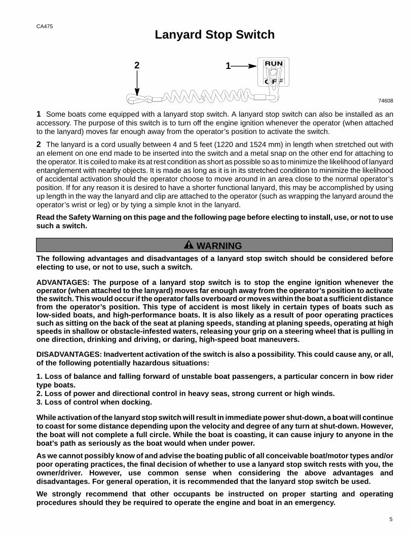
1 Some boats come equipped with a lanyard stop switch. A lanyard stop switch can also be installed as anaccessory. The purpose of this switch is to turn off the engine ignition whenever the operator (when attachedto the lanyard) moves far enough away from the operator’s position to activate the switch.
2 The lanyard is a cord usually between 4 and 5 feet (1220 and 1524 mm) in length when stretched out withan element on one end made to be inserted into the switch and a metal snap on the other end for attaching tothe operator. It is coiled to make its at rest condition as short as possible so as to minimize the likelihood of lanyardentanglement with nearby objects. It is made as long as it is in its stretched condition to minimize the likelihoodof accidental activation should the operator choose to move around in an area close to the normal operator’sposition. If for any reason it is desired to have a shorter functional lanyard, this may be accomplished by usingup length in the way the lanyard and clip are attached to the operator (such as wrapping the lanyard around theoperator’s wrist or leg) or by tying a simple knot in the lanyard.
Read the Safety Warning on this page and the following page before electing to install, use, or not to usesuch a switch.
! WARNINGThe following advantages and disadvantages of a lanyard stop switch should be considered beforeelecting to use, or not to use, such a switch.
ADVANTAGES: The purpose of a lanyard stop switch is to stop the engine ignition whenever theoperator (when attached to the lanyard) moves far enough away from the operator’s position to activatethe switch. This would occur if the operator falls overboard or moves within the boat a sufficient distancefrom the operator’s position. This type of accident is most likely in certain types of boats such aslow-sided boats, and high-performance boats. It is also likely as a result of poor operating practicessuch as sitting on the back of the seat at planing speeds, standing at planing speeds, operating at highspeeds in shallow or obstacle-infested waters, releasing your grip on a steering wheel that is pulling inone direction, drinking and driving, or daring, high-speed boat maneuvers.
DISADVANTAGES: Inadvertent activation of the switch is also a possibility. This could cause any, or all,of the following potentially hazardous situations:
1. Loss of balance and falling forward of unstable boat passengers, a particular concern in bow ridertype boats.2. Loss of power and directional control in heavy seas, strong current or high winds.3. Loss of control when docking.
While activation of the lanyard stop switch will result in immediate power shut-down, a boat will continueto coast for some distance depending upon the velocity and degree of any turn at shut-down. However,the boat will not complete a full circle. While the boat is coasting, it can cause injury to anyone in theboat’s path as seriously as the boat would when under power.
As we cannot possibly know of and advise the boating public of all conceivable boat/motor types and/orpoor operating practices, the final decision of whether to use a lanyard stop switch rests with you, theowner/driver. However, use common sense when considering the above advantages anddisadvantages. For general operation, it is recommended that the lanyard stop switch be used.
We strongly recommend that other occupants be instructed on proper starting and operatingprocedures should they be required to operate the engine and boat in an emergency.
6
CA400
Courtesy of ABYC
1A
1B
2A
2B
3
7
CD327
Exhaust Emissions
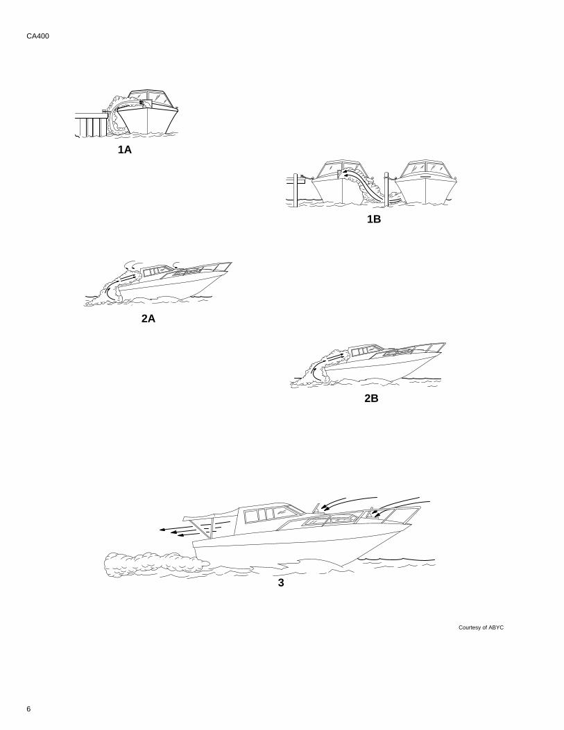
Be Alert To Carbon Monoxide PoisoningCarbon monoxide is produced in the exhaust fumes of all internal combustion engines, including the outboards,sterndrives and inboard engines that propel boats, as well as the generators that power various boataccessories. Carbon monoxide is a deadly gas that is colorless, odorless, and tasteless.
Prolonged exposure to carbon monoxide in sufficient concentration can lead to unconsciousness, brain damage,or death Early symptoms, which should not be confused with seasickness or intoxication, include headache,dizziness, drowsiness, and nausea.
Poor VentilationUnder certain running and/or wind conditions, permanently enclosed or canvas enclosed cabins or cockpits withinsufficient ventilation may draw in carbon monoxide. Install one or more carbon monoxide detectors in suchareas.
Examples of Poor Ventilation:
1 While boat is stationary
A Running the engine when the boat is moored in a confined space.
B Mooring close to another boat that has its engine idling.
2 While boat is moving
A Running the boat with the trim angle of the bow too high.
B Running the boat with no forward hatches open (station wagon effect).
Good VentilationVentilate passenger area, open side curtains, or forward hatches to remove fumes.
Example of Good Ventilation:
3 Desired air flow through the boat.
8
CA281
Safe Boating SuggestionsIn order to safely enjoy the waterways, familiarize yourself with local and other governmental boating regulationsand restrictions, and consider the following suggestions.
• Know and obey all nautical rules and laws of the waterways. Boat operators should complete a boatingsafety course. Courses are offered in the U.S.A. by (1) The U.S. Coast Guard Auxiliary, (2) The Power Squad-ron, (3) The Red Cross and (4) your state or provincial boating law enforcement agency. Inquiries may bemade to the Boating Hotline, 1-800-368-5647 or the Boat U.S. Foundation information number1-800-336-BOAT.
We strongly recommend that all powerboat operators attend one of these courses.
You should also review the NMMA Sources of Waterway Information booklet. It lists regional sources of safety,cruising and local navigation and is available at no charge by writing to:Sources of Waterway InformationNational Marine Manufacturers Association410 N. Michigan AvenueChicago, IL 60611 U.S.A.
• Perform safety checks and required maintenance. Follow a regular schedule and ensure that all repairsare properly made.
• Check safety equipment on board. Here are suggestions of the types of safety equipment to carry whenboating:
(1) Approved fire extinguisher(s); paddle or oar.
(2) Signal devices: flashlight, rockets or flares, flag and whistle or horn.(3) Spare propeller, thrust hubs and an appropriate wrench.
(4) Tools for necessary minor repairs; first aid kit and book.
(5) Anchor and extra anchor line; water-proof storage containers.
(6) Manual bilge pump and extra drain plugs; compass and map or chart of area.
(7) Spare operating equipment; batteries, bulbs, fuses, etc.
(8) Transistor radio
(9) Drinking water
• Know signs of weather change and avoid foul weather and rough-sea boating.
• Tell someone where you are going and when you expect to return.
• Passenger boarding. Stop the engine whenever passengers are boarding, unloading or are near the back(stern) of the boat. Just shifting the drive unit into neutral is not sufficient.
• Use personal flotation devices. Federal Law requires that there be a U. S. Coast Guard approved, wear-able-type life jacket (personal flotation device), correctly sized and readily accessible for every person onboard, plus a throwable cushion or ring. We strongly advise that everyone wear a life jacket at all times whilein the boat.
• Prepare other boat operators. Instruct at least one person on board in the basics of starting and operatingthe engine and boat handling in case the driver becomes disabled or falls overboard.
• Do not overload your boat. Most boats are rated and certified for maximum load (weight) capacities (referto your boat capacity plate). When in doubt, contact your dealer or the boats manufacturer. Know your boat’soperating and loading limitations.
• Make sure everyone in the boat is properly seated. Don’t allow anyone to sit or ride on any part of the boatthat was not intended for such use. This includes backs of seats, gunwales, transom, bow, decks, raised fish-ing seats, any rotating fishing seat; anywhere that sudden unexpected acceleration, sudden stopping, unex-pected loss of boat control or sudden boat movement could cause a person to be thrown overboard or intothe boat.

9
• Never be under the influence of alcohol or drugs while boating (it is the law). They impair your judgmentand greatly reduce your ability to react quickly.
• Know your boating area and avoid hazardous locations.
• Be alert. The operator of the boat is responsible by law to “maintain a proper lookout by sight (and hearing).”The operator must have an unobstructed view particularly to the front. No passengers, load, or fishing seatsshould block the operators view when operating the boat above idle or planing transition speed. Watch “theother guy,” the water and your wake.
• Never drive your boat directly behind a water skier in case the skier falls. As an example, your boat trav-eling at 25 miles per hour (40 km/hr) in 5 seconds will overtake a fallen skier who was 200 feet in front of you.
• Watch fallen skiers. When using your boat for water skiing or similar activities, always keep a fallen or downskier on the operator’s side of the boat while returning to attend the skier. The operator should always havethe down skier in sight and never back up to the skier or anyone in the water.
• Report accidents. Boat operators are required by law to file a Boating Accident Report with their state boat-ing law enforcement agency when their boat is involved in certain boating accidents. A boating accident mustbe reported if (1) there is loss of life or probable loss of life, (2) there is personal injury requiring medical treat-ment beyond first aid, (3) there is damage to boats or other property where the damage value exceeds$500.00 or (4) there is complete loss of the boat. Seek further assistance from local law enforcement.
CA282
Protecting People In The Water
While You Are CruisingIt is very difficult for a person standing or floating in the water to take quick action to avoid a boat heading in his/herdirection even at slow speed.
Always slow down and exercise extreme caution any time you are boating in an area where there might be peoplein the water.
Whenever a boat is moving (coasting) and the drive unit is in neutral position, there is sufficient force by the wateron the propeller to cause the propeller to rotate. This neutral propeller rotation can cause serious injury.
While Boat Is StationaryShift the drive unit into neutral and shut off the engine before allowing people to swim or be in the water nearyour boat.
! WARNINGStop your engine immediately whenever anyone in the water is near your boat. Serious injury to the per-son in the water is likely if contacted by a rotating propeller, a moving boat, a moving gear case, or anysolid device rigidly attached to a moving boat or gear case.
CA283
High-Speed And High-Performance Boat OperationIf your boat is considered a high-speed or high-performance boat with which you are unfamiliar, we recommendthat you never operate it at its high speed capability without first requesting an initial orientation and familiariza-tion demonstration ride with your dealer or an operator experienced with your boat. For additional information,obtain a copy of our “Hi-Performance Boat Operation” booklet (Part Number 90-86168--3) from your dealer, dis-tributor, or Mercury Marine.
10
CD3
Conditions Affecting OperationCD4
Weight DistributionPositioning of weight (passengers and gear) inside the boat has the following effects:
A. Shifting weight to rear (stern) will:
• Generally increases speed and engine RPM.
• At extremes, can cause boat to porpoise.
• Causes bow to bounce in choppy water.
• Increases danger of following wave splashing into boat when coming off plane.
B. Shifting weight to front (bow) will:
• Improves ease of planing on some boats.
• Improves rough water ride.
• At extremes, can cause boat to veer back and forth (bow steer).
CA8
Bottom Of BoatTo maintain maximum speed, the following conditions of the boat bottom should be observed.
A. Clean, free of barnacles and marine growth.
B. Free of distortion; nearly flat where it contacts the water.
C. Straight and smooth, fore and aft.
Marine vegetation may accumulate when boat is docked. This growth must be removed before operation; it mayclog water inlets and cause engine to over heat.
CA9
CavitationCavitation occurs when water flow cannot follow the contour of a fast-moving underwater object, such as a gearhousing or propeller. Cavitation permits the propeller to speed up, but the boat speed to reduce. Cavitation canseriously erode the surface of the gear housing or propeller. Common causes of cavitation are:
A. Weeds or other debris snagged on propeller or gear housing.
B. Bent propeller blade or damaged gear housing skew .
C. Raised burrs or sharp edges on propeller or gear housing.
CA10
VentilationVentilation is caused by surface air or exhaust gases which are introduced around the propeller resulting in pro-peller speedup and a reduction in boat speed. Excessive ventilation is annoying and usually caused by:
A. Drive unit trimmed out too far.
B. A missing propeller diffuser ring.
C. A damaged propeller or gear housing, which allows exhaust gases to escape between propeller and gearhousing.
D. Drive unit installed too high on transom.
11
CD328
Propeller Selection
IMPORTANT: Installed propeller must allow engine to run at its specified maximum wide-open-throttle revolutions per minute (RPM). Use an accurate service tachometer to verify engine operatingRPM.
It is the responsibility of the boat manufacturer and/or the selling dealer to equip the power package with thecorrect propeller(s). Specified engine wide-open-throttle (WOT) and operating RPM range are listed in “SPEC-IFICATIONS”.
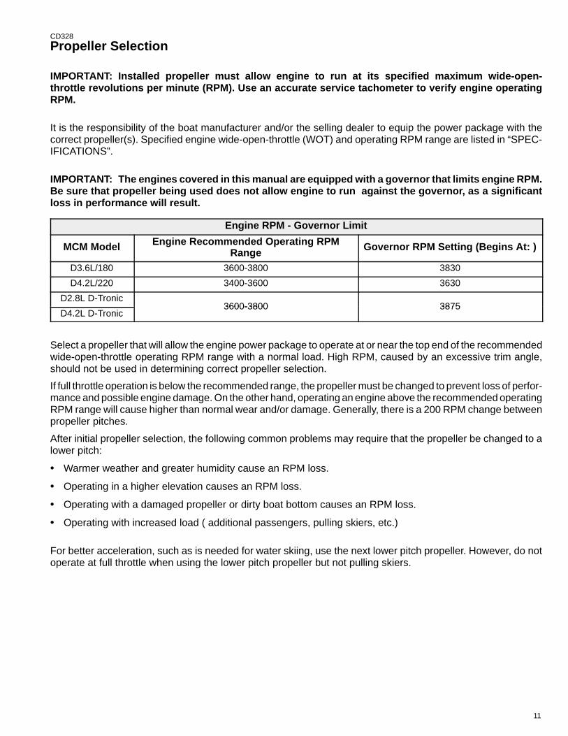
IMPORTANT: The engines covered in this manual are equipped with a governor that limits engine RPM.Be sure that propeller being used does not allow engine to run against the governor, as a significantloss in performance will result.
Engine RPM - Governor Limit
MCM Model Engine Recommended Operating RPMRange Governor RPM Setting (Begins At: )
D3.6L/180 3600-3800 3830
D4.2L/220 3400-3600 3630
D2.8L D-Tronic3600-3800 3875
D4.2L D-Tronic3600-3800 3875
Select a propeller that will allow the engine power package to operate at or near the top end of the recommendedwide-open-throttle operating RPM range with a normal load. High RPM, caused by an excessive trim angle,should not be used in determining correct propeller selection.
If full throttle operation is below the recommended range, the propeller must be changed to prevent loss of perfor-mance and possible engine damage. On the other hand, operating an engine above the recommended operatingRPM range will cause higher than normal wear and/or damage. Generally, there is a 200 RPM change betweenpropeller pitches.
After initial propeller selection, the following common problems may require that the propeller be changed to alower pitch:
• Warmer weather and greater humidity cause an RPM loss.
• Operating in a higher elevation causes an RPM loss.
• Operating with a damaged propeller or dirty boat bottom causes an RPM loss.
• Operating with increased load ( additional passengers, pulling skiers, etc.)
For better acceleration, such as is needed for water skiing, use the next lower pitch propeller. However, do notoperate at full throttle when using the lower pitch propeller but not pulling skiers.
12
CA12
How Elevation And Climate Affect PerformanceElevation has a very noticeable effect on the wide-open-throttle power of an engine. Since air (containing oxy-gen) gets thinner as elevation increases, the engine begins to starve for air. Humidity, barometric pressure andtemperature do have a noticeable effect on the density of air. Heat and humidity thin the air. This condition canbecome particularly annoying when an engine is propped out on a cool, dry day in spring and later, on a hot, sultryday in August, doesn’t have its old zip.
Although some performance can be regained by dropping to a lower-pitch propeller, the basic problem still exists.In some cases, a gear-ratio change to more reduction is possible and very beneficial.
Summer conditions of high temperature, low barometric pressure and high humidity all combine to reduce theengine power. This, in turn, is reflected in decreased boat speeds, as much as 2 or 3 miles per hour in somecases. Nothing will regain this speed for the boater, but the coming of cool, dry weather.
In pointing out the practical consequences of weather effects, an engine -- running on a hot, humid summer day-- may encounter a loss of as much as 14% of the horsepower it would produce on a dry brisk spring or fall day.With the drop in available horsepower, this propeller will, in effect, become too large. Consequently, the engineoperates at less than its recommended RPM. This will result in further loss of horsepower at the propeller withanother decrease in boat speed. This secondary loss, however, can be somewhat regained by switching to alower-pitch propeller that allows the engine to again run at recommended RPM.
For boaters to realize optimum engine performance under changing weather conditions, it is essential that theengine be propped to allow it to operate at or near the top end of the recommended maximum RPM range atwide-open-throttle with a normal boat load.
Not only does this allow the engine to develop full power, but equally important is the fact that the engine alsowill be operating in an RPM range that discourages damaging detonation. This, of course, enhances overall reli-ability and durability of the engine.
13
CD247
Operation And Maintenance
RECOMMENDED OPERATION/DUTY CYCLE
It is the operator’s responsibility to operate within the following recommended operational capability, or dutycycle, as applicable to engine and installation:
• Pleasure Duty -
1.) Operated at rated power and rated speed for short periods of time.
• Light Duty -
1.) Operated such that full rated power at maximum rated RPM is limited to 10% of operating timeand continuous cruising RPM is limited to 90% of Wide-Open-Throttle RPM (when propped withinspecified RPM range).
2.) Annual operating time is not to exceed 500 hours.
NOTE: Pleasure duty rating applies to high performance-type boats, or boats with planing hulls whereacceleration and top speed are of primary importance. This rating is reserved for privately-owned yachts, orrecreational power boats in non-revenue applications.
Light duty rating applies to planing boats where the use of full rated power at maximum rated RPM is limited (asstated above). Examples of Light Duty applications include, but are not limited to: search and rescue craft, fastpatrol boats, fire boats, dive boats, and limited season fishing boats such as sport-fish charter boats. Applicationto common commercial crafts having full-displacement or semi-displacement hulls exceeds the recommendedoperational capability, or duty cycle.
IMPORTANT: Damage caused by improper application or failure to operate within the operationalcapability, or duty cycle, will not be covered by the MerCruiser Diesel Limited Warranty.
14
CE7OWNER/OPERATOR RESPONSIBILITIES
It is the operator’s responsibility to perform all safety checks, ensure that all lubrication and maintenance instruc-tions are complied with for safe operation, and return the unit to an Authorized MerCruiser Dealer for a periodiccheckup.
Normal maintenance service and replacement parts are the responsibility of the owner/operator and as such,are not considered defects in workmanship or material within the terms of the warranty. Individual operating hab-its and usage contribute to the need for maintenance service.
Proper maintenance and care of your power package will assure optimum performance and dependability, andwill keep your overall operating expenses at a minimum. See your Authorized MerCruiser Dealer for service aids.
! CAUTIONThe injection pump lever Wide-Open-Throttle (W.O.T.) Stop Screw adjusts the engine speed governor,and is factory set and sealed. Readjusting the governed speed and operating above the specified RPMwill cause extensive engine damage and/or failure. Removal of the seal and/or readjustment of thegoverned speed is considered misuse of engine, and resulting damages will not be covered by thelimited warranty.
CA14DEALER RESPONSIBILITIES
In general, a dealer’s responsibilities to the customer include predelivery inspection and preparation such as:
• Make sure that the boat is properly equipped.
• Prior to delivery, make certain that the MerCruiser power package and other equipment are in proper operat-ing condition.
• Make all necessary adjustments for maximum efficiency.
• Familiarize the customer with the on-board equipment.
• Explain and demonstrate the operation of the power package and boat.
• At the time of delivery, the dealer should provide you with a copy of a Predelivery Inspection Checklist.
• Your selling dealer should fill out the Warranty Registration Card completely and mail it to the factory (branchor distributor) immediately upon sale of the new product.
15
CD281
Freezing Temperature And Cold Weather OperationIMPORTANT: If boat is operated during periods of freezing temperature, precautions must be taken toprevent freezing damage to power package. Refer to the following and to “Cold Weather or ExtendedStorage” for related information and draining instructions. Damage caused by freezing IS NOT coveredby the MerCruiser Limited Warranty.
! CAUTIONSeawater (raw water) section of cooling system MUST BE COMPLETELY drained for winter storage orimmediately after cold weather use, if the possibility of freezing temperatures exist. Failure to complymay result in trapped water causing freeze and/or corrosion damage to engine.
In order to operate the engine in temperatures of 32° F (0° C) or lower, observe the following instructions:
• At the end of each daily operation, COMPLETELY drain seawater section of cooling system to protect againstdamage by freezing.
• At the end of each daily operation, drain water from water separator, if equipped. Fill fuel tank at end of dailyoperation to prevent condensation.
• Use required permanent-type antifreeze solution to protect components against damage by freezing.
• Be sure to use proper cold weather lubrication oil, and be sure the crankcase contains a sufficient amount.
• Make certain that the battery is of sufficient size and is fully charged. Check that all other electrical equipmentis in optimum condition.
• If operating in arctic temperatures of –20° F (–29° C) or lower, consult your dealer for information about spe-cial cold weather equipment and precautions.
CA17
Drive Unit Impact ProtectionThe Power Trim hydraulic system is designed to provide impact protection for drive unit. If a submerged objectis struck while boat is moving forward, the hydraulic system will cushion kick-up of drive unit as it clears the object,reducing damage to unit. After drive unit has cleared object, the hydraulic system allows drive unit to return tooriginal operating position, preventing loss of steering control and engine over speed.
Use extreme caution when operating in shallow water or where underwater objects are known to be present.Use extreme care to prevent striking submerged objects while operating in REVERSE. No impact protection isprovided in REVERSE.
If drive unit should strike a submerged object, stop engine as soon as possible and inspect drive unit for damage.If damage is present or suspected, boat should be taken to an Authorized MerCruiser Dealer for thorough inspec-tion and necessary repair. Operating a damaged drive unit could cause additional damage to other parts of driveunit, or could affect control of boat. If continued running is necessary, do so at greatly reduced speeds.
IMPORTANT: Impact protection system cannot be designed to ensure total protection from impact dam-age under all conditions.
CA408
Drain Plug and Bilge PumpThe engine compartment in your boat is a natural place for water to collect. For this reason, boats are normallyequipped with a drain plug and/or a bilge pump. It is very important to check these items on a regular basis toensure that the water level does not rise to come in contact with your power package. Components on yourengine will be damaged if submerged. Damage caused by submersion is not covered by the MerCruiser LimitedWarranty.
16
CA20
Launching and Boat Operation Care
! CAUTIONDuring launching from a trailer, if the unloading ramp is steep or the trailer bed must be tilted, the boatmay enter the water rapidly and at a steep angle. This may force water through the exhaust system intothe cylinders. The more weight on the transom, the more likely this is to occur.
Slowing down rapidly, stopping suddenly or backing up rapidly may cause a following wave to “swamp”the transom causing water to enter the cylinders through the exhaust system causing severe enginedamage.
When backing up rapidly, the same situation may occur as stated in the preceding paragraph.
In any of these situations, water entering the engine could cause severe damage to internal parts. Refer to“Attention Required After Submersion,” in this “Operation and Maintenance Manual.”
CA18
Attention Required After Submersion• Before recovery, contact an Authorized MerCruiser Dealer.
• After recovery, immediate service by an Authorized MerCruiser Dealer is required to prevent serious damageto power package.
CA19
Trailering BoatBoat can be trailered with drive unit in up or down position. Adequate road clearance is required between roadand gear housing skew when trailering with drive unit in down position.
If adequate road clearance is a problem, place drive unit in full trailer position and support with an optional trailerkit which is available from your Authorized MerCruiser Dealer.
CA21
Stolen Power PackageIf your power package is stolen, immediately advise the local authorities and Mercury Marine of the model andserial number(s) and to whom the recovery is to be reported. This “Stolen Motor” information is placed into a fileat Mercury Marine to aid authorities and dealers in recovery of stolen motors.
17
CE9
Replacement Service PartsMarine engines are expected to operate at or near full throttle for most of their life. They are also expected tooperate in both fresh and saltwater environments. These conditions require numerous special parts. Care shouldbe exercised when replacing marine engine parts, as specifications are quite different from those of the standardautomotive engine.
Since marine engines must be capable of running at or near maximum RPM much of the time, special pistons,camshafts and other heavy-duty moving parts are required for long life and peak performance.
These are but a few of the many special modifications that are required in MerCruiser marine engines to providelong life and dependable performance.
CA410
Do-It-Yourself Maintenance SuggestionsIf you are one of those persons who likes to do-it-yourself, here are some suggestions for you.
• Present-day marine equipment, such as your MerCruiser power package, are highly technical pieces ofmachinery. Electronic ignition and special fuel delivery systems provide greater fuel economies, but also aremore complex for the untrained mechanic.
• Do not attempt any repairs which are not covered in this manual unless you are aware of the precautions(“Cautions” and “Warnings”) and procedures required. Your safety is of our concern.
• If you attempt to service the product yourself, we suggest you order the maintenance procedures manual forthat model. This manual outlines the correct procedures to follow. Do not attempt repairs if you do notunderstand the procedures.
• There are special tools and equipment that are required to perform some repairs. Do not attempt these repairsunless you have these special tools and/or equipment. You can cause damage to the product in excess ofthe cost a dealer would charge you.
• Also, if you partially disassemble an engine or drive assembly and are unable to repair it, the dealer’smechanic must reassemble the components and test to determine the problem. This will cost you more thantaking it to the dealer immediately upon having a problem. It may be a very simple adjustment to correct theproblem.
• Do not telephone the dealer, service office or the factory to attempt for them to diagnose a problem or requestthe repair procedure. It is difficult for them to diagnose a problem over the telephone.
• Your Authorized Dealer is there to service your power package. They have qualified factory-trainedmechanics.
It is recommended you have the dealer do periodic maintenance checks on your power package. Have themwinterize it in the fall and service it before the boating season. This will reduce the possibility of any problemsoccurring during your boating season when you want trouble-free boating pleasure.
CD329
Diagnosing EDI Problems (If So Equipped)Your Authorized MerCruiser Dealer has the proper service tools for diagnosing problems on Electronic DieselInjection (EDI) Systems. The Electronic Control Module (ECM) on these engines have the ability to detect someproblems with the system when they occur, and store a “Trouble Code” in the ECM’s memory. This code canthen be read later by a service technician using a special diagnostic tool.

18
CD330
Engine Break-In
INITIAL BREAK-IN PROCEDURE
It is especially important that the following procedure be used on new diesel engines. This break-in procedureallows the proper seating of the pistons and rings, which greatly reduces the likelihood of problems.
IMPORTANT: It is recommended that the boat not be accelerated hard until this procedure has beencompleted.
IMPORTANT: Never operate the starter motor longer than 15 seconds at a time, to avoid overheating thestarter motor. If engine does not start, wait 1 minute to allow the starter motor to cool; then, repeat start-ing procedure.
Initial Break-in Procedure Is As Follows:
1. Follow instructions “a” or “b”: a. On D2.8L D-Tronic and D4.2L D-Tronic Engines: Proceed to Step2.b. On D3.6L/180 and D4.2L/220 Engines Only: Pre-lubricate the turbocharger and engine. To do this,
hold the “STOP” switch toggle lever DOWN while you simultaneously turn the key switch to “START”position for 15 seconds. This will rotate the starter motor and engine/oil pump. During this processthe engine will not run because no fuel is injected. Allow the starter motor to cool down for one minuteand repeat the above described process. To avoid overheating the starter motor, do not engage startermotor for more than 15 seconds each time.
2. Refer to appropriate “Starting, Shifting and Stopping” section and start engine. Allow engine to idle until ithas reached normal operating temperature.
3. Run engine in gear for 3 minutes at each of the following RPMs: 1200 RPM, 2400 RPM and 3000 RPM.
4. Run engine in gear for 3 minutes at each of the following RPMs: 1500 RPM, 2800 RPM and 3400 RPM.
5. Run engine in gear for 3 minutes at each of the following RPMs: 1800 RPM, 3000 RPM and Maximum RatedFull-Throttle RPM.
CE1120-HOUR BREAK-IN PERIOD
IMPORTANT: The first 20 hours of operation is the engine break-in period. Correct break-in is essentialto obtain minimum oil consumption and maximum engine performance. During this break-in period, thefollowing rules must be observed:
• DO NOT operate engine below 1500 RPM for extended periods during the first 10 hours. During this period,shift into gear as soon as possible after starting engine and advance throttle so that RPM is above 1500 (pro-vided that conditions permit safe operation at this speed).
• DO NOT operate at any one constant speed for extended periods.
• DO NOT exceed 75% of full throttle during the first 10 hours except during engine Initial Break-In Procedure.During the next 10 hours, occasional operation at full throttle (5 minutes at a time maximum) is permissible.
• AVOID full throttle acceleration from stopped position.
• DO NOT operate at full throttle until engine reaches normal operating temperature.
• OBSERVE INSTRUMENTS, if an abnormal reading occurs, stop engine immediately and determine cause.
• FREQUENTLY CHECK crankcase oil and stern drive unit fluid levels. Add if necessary. It is normal for oil con-sumption to be somewhat high during the break-in period.
• AT END OF 20-HOUR break-in period, remove break-in oil and replace oil filter. Fill crankcase with correctgrade and viscosity oil.
19
CA211
After Break-In PeriodTo help extend the life of your MerCruiser power package, the following recommendations should be considered;
• Use a propeller that allows the engine to operate at or near the top of the maximum RPM range (See“Specifications” section) when at full throttle with a normal boat load.
• Operation at 3/4 throttle setting or lower is recommended. Refrain from prolonged operation at maximum (fullthrottle) RPM.
CA414
End of First Season CheckupAt the end of the first season of operation, an Authorized MerCruiser Dealer should be contacted to discussand/or perform various scheduled maintenance items. If you are in an area where the product is operatedcontinuously (year-round operation), you should contact your dealer at the end of the first 100 hours of operation,or once yearly, whichever occurs first.
20
CD7
Specifications
CD11
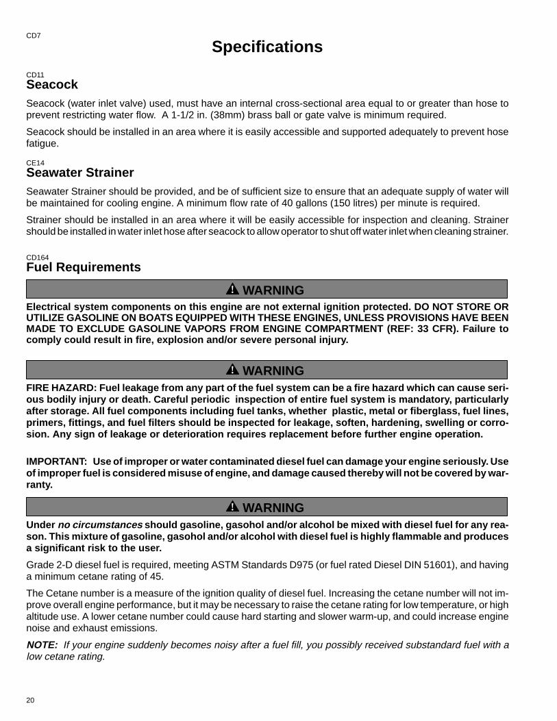
SeacockSeacock (water inlet valve) used, must have an internal cross-sectional area equal to or greater than hose toprevent restricting water flow. A 1-1/2 in. (38mm) brass ball or gate valve is minimum required.
Seacock should be installed in an area where it is easily accessible and supported adequately to prevent hosefatigue.
CE14
Seawater StrainerSeawater Strainer should be provided, and be of sufficient size to ensure that an adequate supply of water willbe maintained for cooling engine. A minimum flow rate of 40 gallons (150 litres) per minute is required.
Strainer should be installed in an area where it will be easily accessible for inspection and cleaning. Strainershould be installed in water inlet hose after seacock to allow operator to shut off water inlet when cleaning strainer.
CD164
Fuel Requirements
! WARNINGElectrical system components on this engine are not external ignition protected. DO NOT STORE ORUTILIZE GASOLINE ON BOATS EQUIPPED WITH THESE ENGINES, UNLESS PROVISIONS HAVE BEENMADE TO EXCLUDE GASOLINE VAPORS FROM ENGINE COMPARTMENT (REF: 33 CFR). Failure tocomply could result in fire, explosion and/or severe personal injury.
! WARNINGFIRE HAZARD: Fuel leakage from any part of the fuel system can be a fire hazard which can cause seri-ous bodily injury or death. Careful periodic inspection of entire fuel system is mandatory, particularlyafter storage. All fuel components including fuel tanks, whether plastic, metal or fiberglass, fuel lines,primers, fittings, and fuel filters should be inspected for leakage, soften, hardening, swelling or corro-sion. Any sign of leakage or deterioration requires replacement before further engine operation.
IMPORTANT: Use of improper or water contaminated diesel fuel can damage your engine seriously. Useof improper fuel is considered misuse of engine, and damage caused thereby will not be covered by war-ranty.
! WARNINGUnder no circumstances should gasoline, gasohol and/or alcohol be mixed with diesel fuel for any rea-son. This mixture of gasoline, gasohol and/or alcohol with diesel fuel is highly flammable and producesa significant risk to the user.
Grade 2-D diesel fuel is required, meeting ASTM Standards D975 (or fuel rated Diesel DIN 51601), and havinga minimum cetane rating of 45.
The Cetane number is a measure of the ignition quality of diesel fuel. Increasing the cetane number will not im-prove overall engine performance, but it may be necessary to raise the cetane rating for low temperature, or highaltitude use. A lower cetane number could cause hard starting and slower warm-up, and could increase enginenoise and exhaust emissions.
NOTE: If your engine suddenly becomes noisy after a fuel fill, you possibly received substandard fuel with alow cetane rating.
21
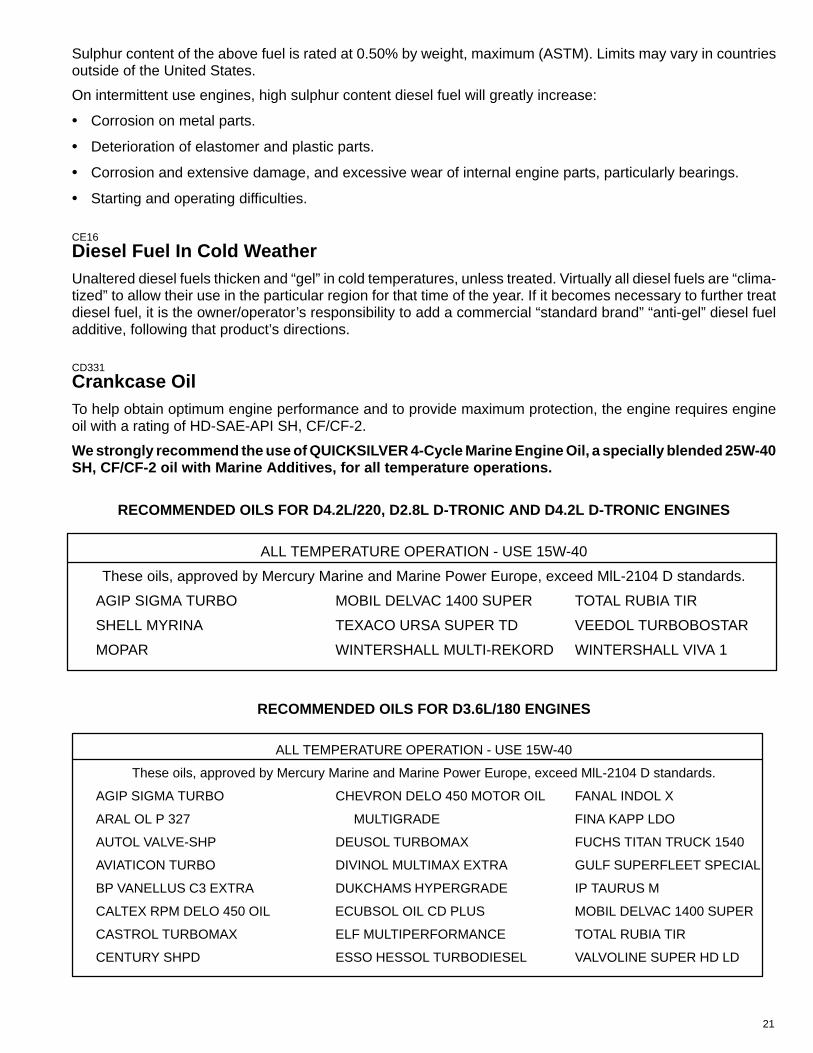
Sulphur content of the above fuel is rated at 0.50% by weight, maximum (ASTM). Limits may vary in countriesoutside of the United States.
On intermittent use engines, high sulphur content diesel fuel will greatly increase:
• Corrosion on metal parts.
• Deterioration of elastomer and plastic parts.
• Corrosion and extensive damage, and excessive wear of internal engine parts, particularly bearings.
• Starting and operating difficulties.
CE16
Diesel Fuel In Cold WeatherUnaltered diesel fuels thicken and “gel” in cold temperatures, unless treated. Virtually all diesel fuels are “clima-tized” to allow their use in the particular region for that time of the year. If it becomes necessary to further treatdiesel fuel, it is the owner/operator’s responsibility to add a commercial “standard brand” “anti-gel” diesel fueladditive, following that product’s directions.
CD331
Crankcase OilTo help obtain optimum engine performance and to provide maximum protection, the engine requires engineoil with a rating of HD-SAE-API SH, CF/CF-2.
We strongly recommend the use of QUICKSILVER 4-Cycle Marine Engine Oil, a specially blended 25W-40SH, CF/CF-2 oil with Marine Additives, for all temperature operations.
RECOMMENDED OILS FOR D4.2L/220, D2.8L D-TRONIC AND D4.2L D-TRONIC ENGINES
ALL TEMPERATURE OPERATION - USE 15W-40
These oils, approved by Mercury Marine and Marine Power Europe, exceed MlL-2104 D standards.
AGIP SIGMA TURBO MOBIL DELVAC 1400 SUPER TOTAL RUBIA TIR
SHELL MYRINA TEXACO URSA SUPER TD VEEDOL TURBOBOSTAR
MOPAR WINTERSHALL MULTI-REKORD WINTERSHALL VIVA 1
RECOMMENDED OILS FOR D3.6L/180 ENGINES
ALL TEMPERATURE OPERATION - USE 15W-40
These oils, approved by Mercury Marine and Marine Power Europe, exceed MlL-2104 D standards.
AGIP SIGMA TURBO CHEVRON DELO 450 MOTOR OIL FANAL INDOL X
ARAL OL P 327 MULTIGRADE FINA KAPP LDO
AUTOL VALVE-SHP DEUSOL TURBOMAX FUCHS TITAN TRUCK 1540
AVIATICON TURBO DIVINOL MULTIMAX EXTRA GULF SUPERFLEET SPECIAL
BP VANELLUS C3 EXTRA DUKCHAMS HYPERGRADE IP TAURUS M
CALTEX RPM DELO 450 OIL ECUBSOL OIL CD PLUS MOBIL DELVAC 1400 SUPER
CASTROL TURBOMAX ELF MULTIPERFORMANCE TOTAL RUBIA TIR
CENTURY SHPD ESSO HESSOL TURBODIESEL VALVOLINE SUPER HD LD
22
CD332
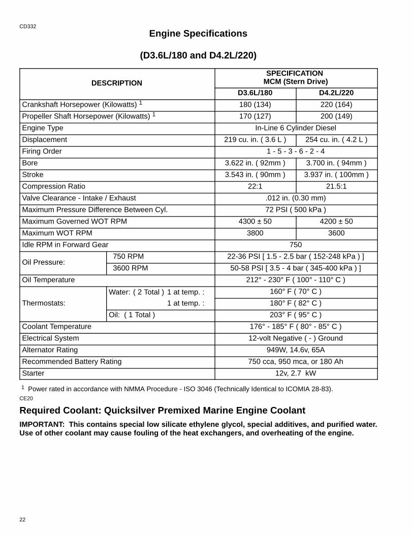
Engine Specifications
(D3.6L/180 and D4.2L/220)
DESCRIPTIONSPECIFICATION
MCM (Stern Drive)
D3.6L/180 D4.2L/220
Crankshaft Horsepower (Kilowatts) 1 180 (134) 220 (164)
Propeller Shaft Horsepower (Kilowatts) 1 170 (127) 200 (149)
Engine Type In-Line 6 Cylinder Diesel
Displacement 219 cu. in. ( 3.6 L ) 254 cu. in. ( 4.2 L )
Firing Order 1 - 5 - 3 - 6 - 2 - 4
Bore 3.622 in. ( 92mm ) 3.700 in. ( 94mm )
Stroke 3.543 in. ( 90mm ) 3.937 in. ( 100mm )
Compression Ratio 22:1 21.5:1
Valve Clearance - Intake / Exhaust .012 in. (0.30 mm)
Maximum Pressure Difference Between Cyl. 72 PSI ( 500 kPa )
Maximum Governed WOT RPM 4300 ± 50 4200 ± 50
Maximum WOT RPM 3800 3600
Idle RPM in Forward Gear 750
Oil Pressure: 750 RPM 22-36 PSI [ 1.5 - 2.5 bar ( 152-248 kPa ) ]
Oil Pressure: 3600 RPM 50-58 PSI [ 3.5 - 4 bar ( 345-400 kPa ) ]
Oil Temperature 212° - 230° F ( 100° - 110° C )
Th
Water: ( 2 Total ) 1 at temp. : 160° F ( 70° C )
Thermostats: 1 at temp. : 180° F ( 82° C )
Oil: ( 1 Total ) 203° F ( 95° C )
Coolant Temperature 176° - 185° F ( 80° - 85° C )
Electrical System 12-volt Negative ( - ) Ground
Alternator Rating 949W, 14.6v, 65A
Recommended Battery Rating 750 cca, 950 mca, or 180 Ah
Starter 12v, 2.7 kW
1 Power rated in accordance with NMMA Procedure - ISO 3046 (Technically Identical to ICOMIA 28-83).CE20
Required Coolant: Quicksilver Premixed Marine Engine CoolantIMPORTANT: This contains special low silicate ethylene glycol, special additives, and purified water.Use of other coolant may cause fouling of the heat exchangers, and overheating of the engine.
23
CD333
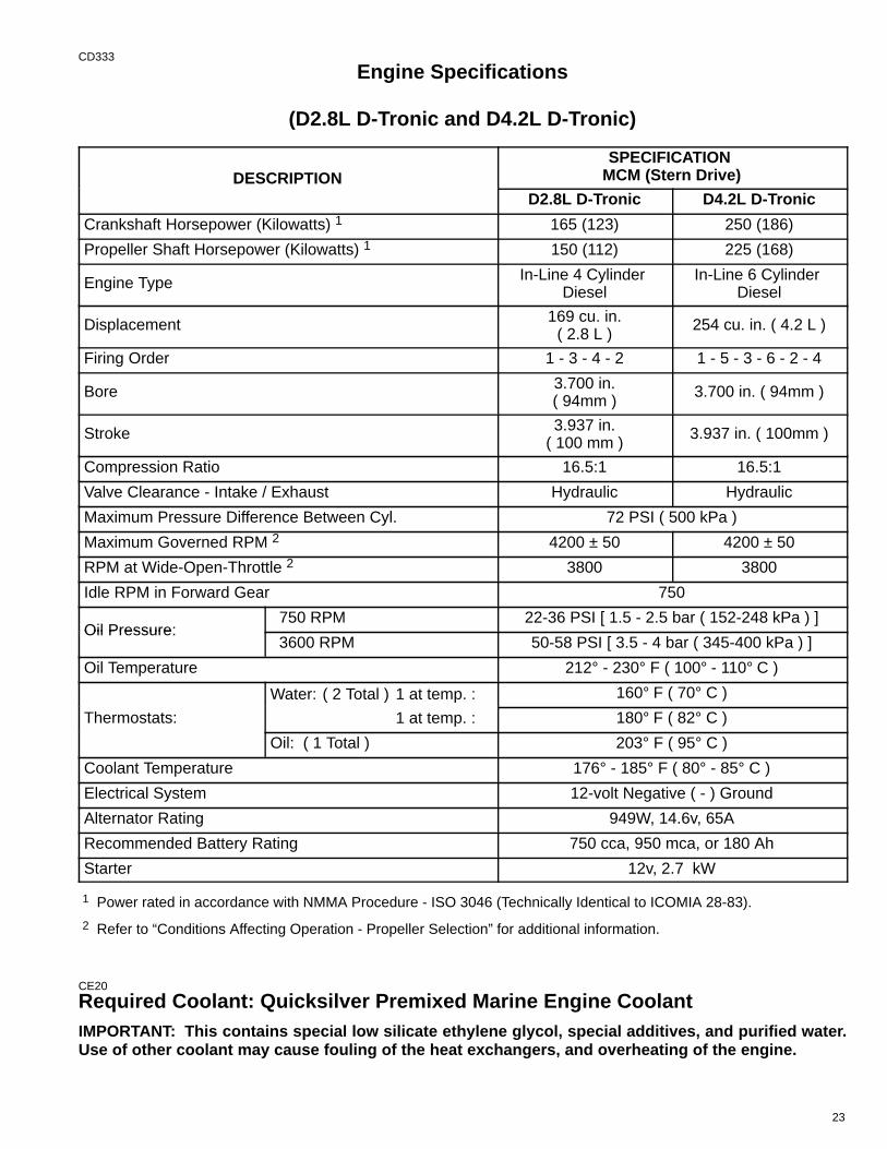
Engine Specifications
(D2.8L D-Tronic and D4.2L D-Tronic)
DESCRIPTIONSPECIFICATION
MCM (Stern Drive)
D2.8L D-Tronic D4.2L D-Tronic
Crankshaft Horsepower (Kilowatts) 1 165 (123) 250 (186)
Propeller Shaft Horsepower (Kilowatts) 1 150 (112) 225 (168)
Engine Type In-Line 4 Cylinder Diesel
In-Line 6 Cylinder Diesel
Displacement 169 cu. in.( 2.8 L )
254 cu. in. ( 4.2 L )
Firing Order 1 - 3 - 4 - 2 1 - 5 - 3 - 6 - 2 - 4
Bore 3.700 in.( 94mm )
3.700 in. ( 94mm )
Stroke 3.937 in.( 100 mm )
3.937 in. ( 100mm )
Compression Ratio 16.5:1 16.5:1
Valve Clearance - Intake / Exhaust Hydraulic Hydraulic
Maximum Pressure Difference Between Cyl. 72 PSI ( 500 kPa )
Maximum Governed RPM 2 4200 ± 50 4200 ± 50
RPM at Wide-Open-Throttle 2 3800 3800
Idle RPM in Forward Gear 750
Oil Pressure: 750 RPM 22-36 PSI [ 1.5 - 2.5 bar ( 152-248 kPa ) ]
Oil Pressure: 3600 RPM 50-58 PSI [ 3.5 - 4 bar ( 345-400 kPa ) ]
Oil Temperature 212° - 230° F ( 100° - 110° C )
Th
Water: ( 2 Total ) 1 at temp. : 160° F ( 70° C )
Thermostats: 1 at temp. : 180° F ( 82° C )
Oil: ( 1 Total ) 203° F ( 95° C )
Coolant Temperature 176° - 185° F ( 80° - 85° C )
Electrical System 12-volt Negative ( - ) Ground
Alternator Rating 949W, 14.6v, 65A
Recommended Battery Rating 750 cca, 950 mca, or 180 Ah
Starter 12v, 2.7 kW
1 Power rated in accordance with NMMA Procedure - ISO 3046 (Technically Identical to ICOMIA 28-83).
2 Refer to “Conditions Affecting Operation - Propeller Selection” for additional information.
CE20
Required Coolant: Quicksilver Premixed Marine Engine CoolantIMPORTANT: This contains special low silicate ethylene glycol, special additives, and purified water.Use of other coolant may cause fouling of the heat exchangers, and overheating of the engine.
24
CD334
3
2
1
5
7
71856
71856
71856
4 72753
6
71772
71856
71856 718868B
73546
9 735478A
25
CD9
Operation
CD335
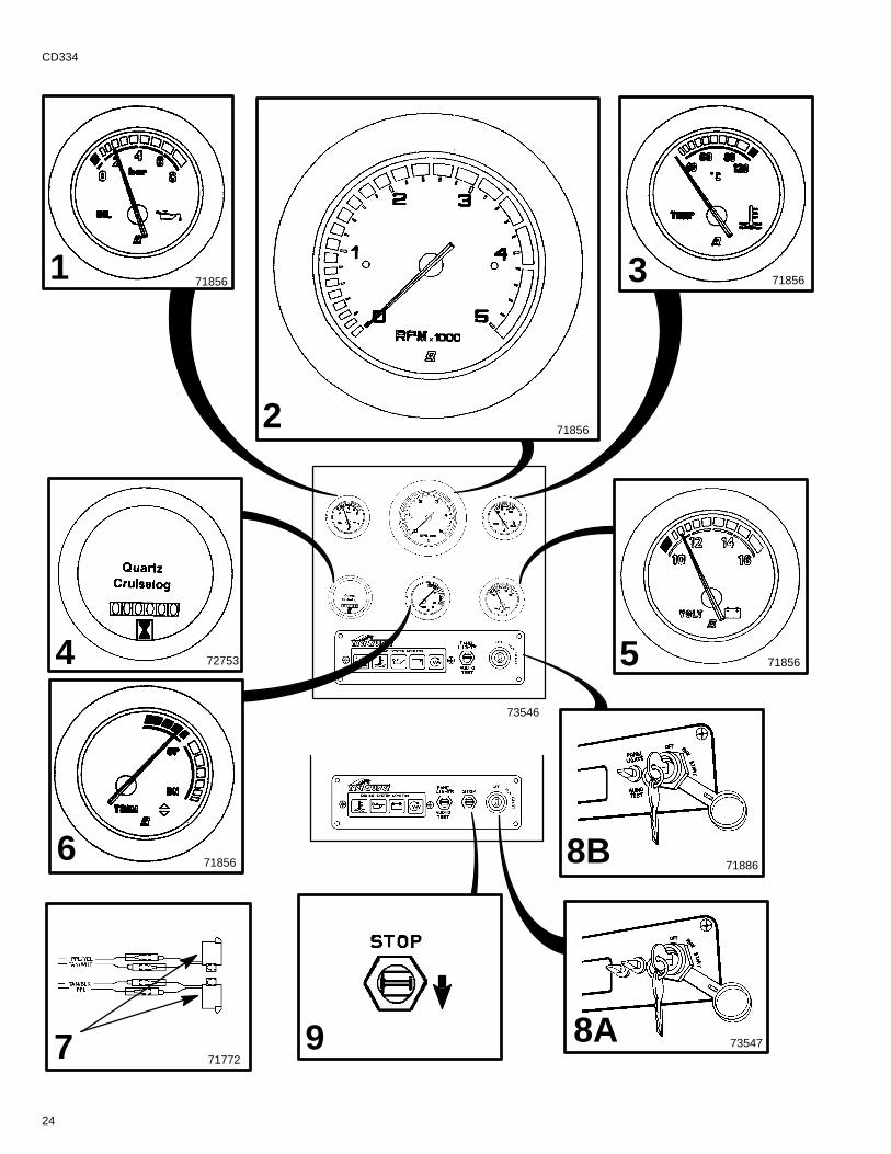
Quicksilver Instruments and Instrumentation
Shown is the basic Quicksilver instrumentation and engine system monitor display for the Diesel Power Pack-age. The instrumentation shown is required for safe operation of boat and engine. Operator should become fa-miliar with all instrumentation before operating the engines.
Gauges and engine system monitor panel may be individually mounted, or collectively mounted in the optionalsingle panel available from Quicksilver.
NOTE: Refer to manufacturer’s instructions and explanations about instrumentation, if equipped with other thanQuicksilver instrumentation.
1 Oil Pressure Gauge - indicates engine oil pressure. Refer to “Specifications” for normal operating readings.
2 Tachometer - indicates engine speed (RPM).
3 Coolant Temperature Gauge - indicates engine coolant temperature. Refer to “Specifications” for normaloperating readings.
4 Cruise Log (Engine Hour Meter) - records engine running time.
5 Voltmeter- indicates battery voltage, and if alternator and charging circuit are functioning properly. The greenarea on the gauge is the normal operating range.
6 Trim/Tilt Gauge - indicates drive unit trim angle (“Up/Out” or “Down/In”).
7 Audio Warning Buzzer Standard Features - Buzzer sounds if:
(1) Cooling system temperature too high(2) Oil pressure too low(3) Drive unit oil too low
8 Key Switch - has three positions. In the “OFF” position, all electrical circuits are off and engine cannot bestarted. In the “RUN” position, all electrical circuits, indicator lamps, automatic preheating (if so equipped) andall instruments are operational. In the “START” position the engine can be started.
NOTE: Key can only be removed in the “OFF” position.
A D3.6L/180 and D4.2L/220 - If engine is running the key switch cannot be used to stop engine. The enginecan only be stopped by using the Engine Stop Switch, while the Key Switch is in the “RUN” position. No electri-cal circuit is operational when the key switch is turned to the “OFF” position.
B D2.8L D-Tronic and D4.2L D-Tronic - The engine is stopped when the key switch is turned to the “OFF” posi-tion.
9 Engine Stop Switch - D3.6L/180 and D4.2L/220 - is used to stop the engine. This is done by electricallyshutting off fuel delivery system. Stop Switch is toggled “DOWN” and held until engine stops completely. Then,key switch can be turned to the “OFF” position.
26
CD336
71891
32
1
71722
71891
BCD AE
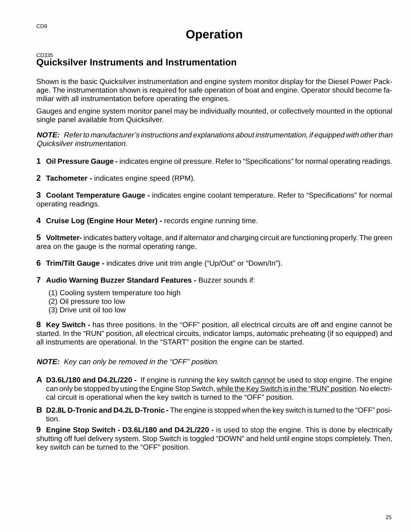
CD3371 Engine System Monitor Features - The appropriate light functions as follows:
A Preheat Indicator Lamp - lights up when the glow plugs, if so equipped, are preheating the combustion cham-bers. The light stays on until the preheat period is complete. The timed preheat period begins when the keyswitch is turned on, and then, only when the engine is cold. THE ENGINE CAN BE STARTED ONLY AFTERTHE LIGHT GOES OUT.
B Charge Indicator Lamp - indicates a problem with charging system if lamp illuminates while engine is running.Lamp will light when key switch is “ON” and engine is not running. When engine starts, light should go off.
C Oil Pressure Warning Lamp - indicates low engine oil pressure if lamp illuminates while engine is running.
D Coolant Temperature Warning Lamp - indicates excessive engine coolant temperature if lamp illuminateswhile engine is running.
NOTE: The coolant temperature warning lamp is wired in a parallel circuit with the gear lube monitor bottleswitch. If lamp illuminates while engine is running, and coolant temperature and coolant level are normal, thismay be an indication of low oil level in the gear lube monitor bottle. The cause should be determined and cor-rected.
E Trouble Code Warning Lamp (D2.8L D-Tronic and D4.2L D-Tronic Only) - additional lamp indicates whena problem exists that requires service, if lamp illuminates while engine is running.
2 Panel Lights / Audio Test Switch - has three positions; in the normal position all electrical circuits operatein a standard fashion (as described above). With switch toggled “UP” the instrumentation lights are all illumi-nated. When the switch is toggled “DOWN” the audio warning buzzer will sound allowing the operator to performa test of the audio warning buzzer.
3 20 Amp Fuse and Holder - located in-line on key switch RED/PURPLE wire and protects the Instrumentationand wiring should an electrical overload occur. If an overload occurs, the fuse will burn out. Check “blown”(burned) fuse if key is turned to RUN or START and nothing happens.
IMPORTANT: Cause for overload must be determined and corrected before attempting to install newfuse or fuse failure will occur again.
After cause is corrected, install new fuse and check systems to function.
27
CD277
1
22444
3 7163074703
42
73546 71856
CD87
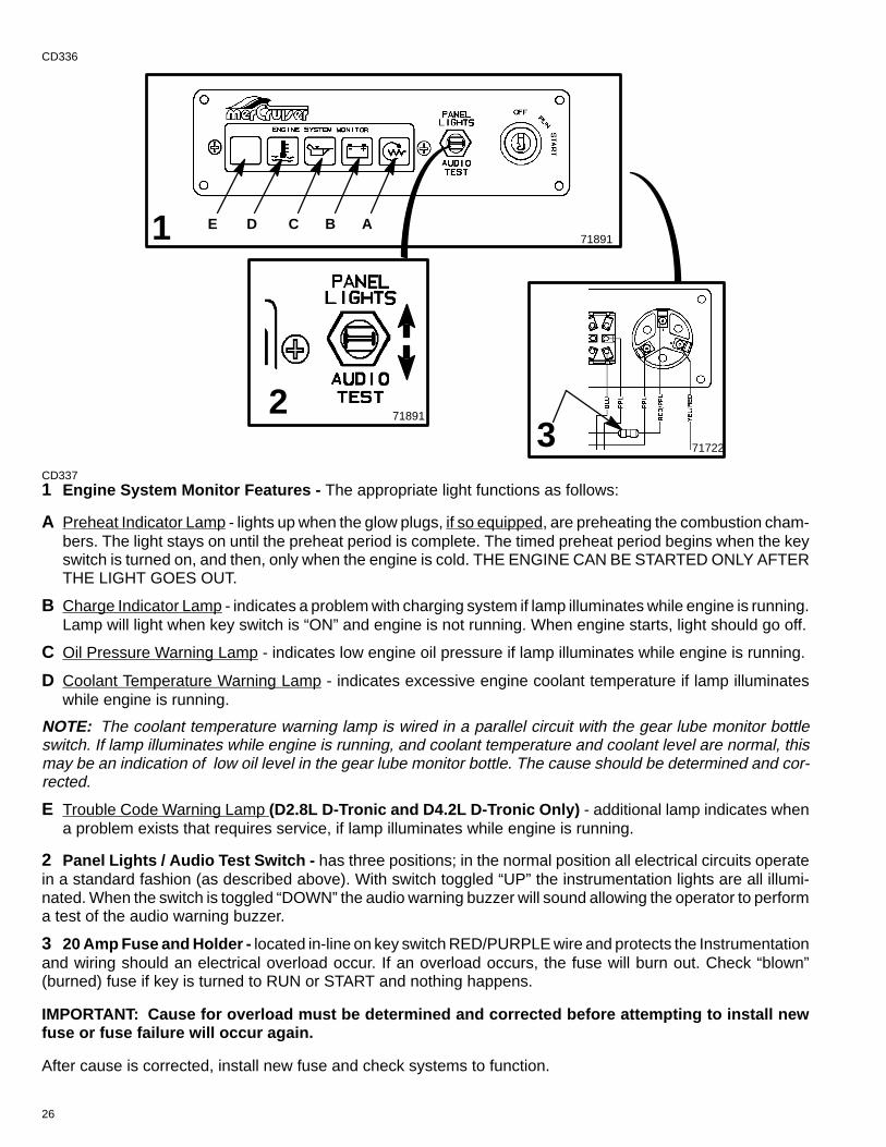
Electrical System Overload Protectionlf an electrical overload occurs, a fuse will blow or a circuit breaker will trip open.
IMPORTANT: The cause must be found and corrected before replacing fuse or resetting circuit breaker.
1 Two 60 amp circuit breakers provide protection for engine wiring harness and instrumentation power lead.Reset by pushing RESET button IN (on outside).
In an emergency, when engine must be operated and cause for high current draw cannot be located and cor-rected, turn OFF or disconnect all accessories connected to engine and instrumentation wiring. Reset circuitbreaker. If breaker remains open, electrical overload has not been eliminated. Further checks must be made onelectrical system.
2 When equipped with Quicksilver instrumentation and wiring a 20 amp fuse and holder is located in-line onkey switch RED/PURPLE wire and protects the Instrumentation and wiring should an electrical overload occur.If an overload occurs, the fuse will burn out. Check “blown” (burned) fuse if key is turned to RUN or START andinstruments do not work and/or if switches do not function.
3 The Power Trim system is protected from overload by 110 amp fuse and a 20 amp in-line fuse on Power Trimpump.
CA31
Mercathode System4 A 20 amp in-line fuse is in the wire which connects to positive (+) terminal on controller. If fuse is “blown” (de-fective), the system will not operate.
28
CD197
1
45
23
6
7
811
9
10
9
11
10
8
13
12
12
29
CD9
OperationCD195
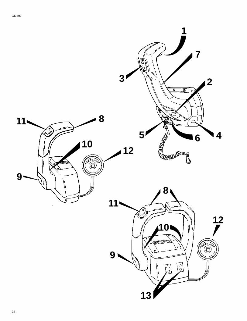
Remote Controls (Panel Mounted)Your boat may be equipped with one of many Quicksilver remote controls available. All controls feature anintegral safety switch that allows starting engine in NEUTRAL only. Also, all controls may not have all featuresshown.
NOTE: If boat is equipped with a remote control other than shown, consult your dealer for a description and/ordemonstration of the control.
1 Neutral Lock Bar - Prevents accidental shift and throttle engagement. Neutral lock bar must be pulled “Up”to move the control handle out of neutral.
2 Throttle Only Button - Allows engine throttle advancement without shifting the engine. This is done by disen-gaging the shift mechanism from the control handle. The throttle only button can be depressed only when theremote control handle is in the “Neutral” position, and should only be used to assist in starting the engine.
3 Power Trim Switch - See “Power Trim” for detailed power trim operating procedures.
4 Trailer Switch - Used to raise drive unit for trailering, launching, breaching or shallow water operation. See“Power Trim” for detailed trailer switch operation.
5 Lanyard Stop Switch - Turns ignition “Off” whenever the operator (when attached to the lanyard) moves farenough away from the operator’s position to activate the switch. See “Lanyard Stop Switch” at the front of thismanual for safety warning on the use of this switch.
6 Control Handle Tension Adjustment Screw - This screw can be adjusted to “Increase” or “Decrease” thetension on the control handle. This will help prevent “Creep” of the remote control handle. Turn screw “Clockwise”to increase tension and “Counterclockwise” to decrease tension. Adjust to tension desired.
7 Control Handle - Operation of the shift and throttle are controlled by the movement of the control handle.“Push” the control handle forward from “Neutral” with a quick firm motion to the first detent for “Forward” gear.Continue pushing forward to increase speed. Pull the control handle back from “Neutral” with a quick firm motionto the first detent for “Reverse” gear. Continue pushing back to increase speed.
CD196
Remote Controls (Console Mounted)Your boat may be equipped with one of many Quicksilver remote controls available. All controls feature anintegral safety switch that allows starting engine in NEUTRAL only. Also, all controls may not have all featuresshown.
NOTE: If boat is equipped with a remote control other than shown, consult your dealer for a description and/ordemonstration of the control.
8 Control Handle(s) - Operation of the the shift and throttle are controlled by the movement of the control han-dle. “Push” the control handle forward from “Neutral” with a quick firm motion to the first detent for “Forward” gear.Continue pushing forward to increase speed. Pull the control handle back from “Neutral” with a quick firm motionto the first detent for “Reverse” gear. Continue pushing back to increase speed.
9 Throttle Only Button - Allows engine throttle advancement without shifting the engine. This is done by disen-gaging the shift mechanism from the control handle. The throttle only button can be depressed only when theremote control handle is in the “Neutral” position, and should only be used to assist in starting the engine.10Control Handle Tension Adjustment Screw - This screw can be adjusted to “Increase” or “Decrease” thetension on the control handle (cover must be removed to adjust). This will help prevent “Creep” of the remotecontrol handle. Turn screw “Clockwise” to increase tension and “Counterclockwise” to decrease tension. Adjustto tension desired.
11 Power Trim Switch - See “Power Trim” section for detailed power trim operating procedures.
12Trailer Switch - Used to raise drive unit for trailering, launching, breaching or shallow water operation. See“Power Trim” for detailed trailer switch operation.
13Power Trim Adjustment Switches (Used on Three Button Trim Control Only) - See “Power Trim” sectionfor detailed power trim operating procedures.
30
CD198
3
4
7053771339
1 2
713385
3° – 5°
31
CD217
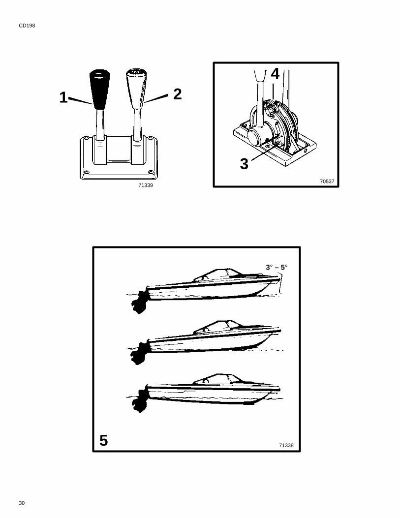
Remote Controls (Two Lever)Your boat may be equipped with one of many Quicksilver remote controls available. All controls feature an inte-gral safety switch that allows starting engine in NEUTRAL only. Also, all controls may not have all features shown.
NOTE: If boat is equipped with a remote control other than shown, consult your dealer for a description and/ordemonstration of the control.
1 Shift Lever - shifts unit into gear with full lever movement. Move lever forward to shift to FORWARD gear.Move lever backward to shift to REVERSE gear. Lever in full vertical position shifts to NEUTRAL.
! CAUTIONNever shift unit into or out of gear unless throttle lever is a idle RPM.2 Throttle Lever - allows engine RPM to be increased or decreased.
3 FRICTION Screw - adjusts control handle friction so motor speed can be set and driver does not have to holdhandle.
Turn screw clockwise to increase friction. Do not thread screw all the way out.
4 DETENT Screw - controls the effort needed to move control handle out of NEUTRAL. To increase tension,turn screw clockwise; to decrease, turn screw counterclockwise. Do not thread screw all the way out.
IMPORTANT: Boats equipped with dual power packages may have both shift levers on one control andboth throttle levers on the other control.CA284
Power TrimPower Trim allows the operator to adjust the drive angle, while underway, to provide the ideal boat angle for vary-ing load and water conditions. Also, the Power Trim system “Trailering” feature allows the operator to raise andlower the drive unit for trailering, beaching, launching and low speed (below 1200 RPM engine speed), shallowwater operation.
! CAUTIONNever trim the drive unit UP/OUT using TRAILER switch while boat is underway at engine speeds above1200 RPM. Use extreme caution when operating with drive unit raised. Severe damage to the drive unitmay result if unit is raised beyond the gimbal ring support flanges at engine speeds above 1200 RPM.
5 In most cases, best overall performance is obtained with the drive unit adjusted so the boat bottom will runat a 3° to 5° angle to the water.
Trimming Drive Unit UP/OUT Can:
• Lower the bow.
• Generally increase top speed.
• Increase clearance over submerged objects or a shallow bottom.
• Cause boat to accelerate and plane off slower.
• In excess, cause boat “porpoising” (bouncing) or propeller ventilation.
• Cause engine overheating if trimmed UP/OUT to a point where any cooling water intake holes are above thewater line.
Trimming Drive Unit DOWN/IN Can:
• Help the boat accelerate and plane off quicker.
• Generally improve the ride in choppy water.
• In most cases, reduce boat speed.
• If in excess, lower the bow of some boats to a point at which they begin to plow with their bow in the waterwhile on plane. This can result in an unexpected turn in either direction called “bow steering” or “over steering”if any turn is attempted, or if a significant wave is encountered.
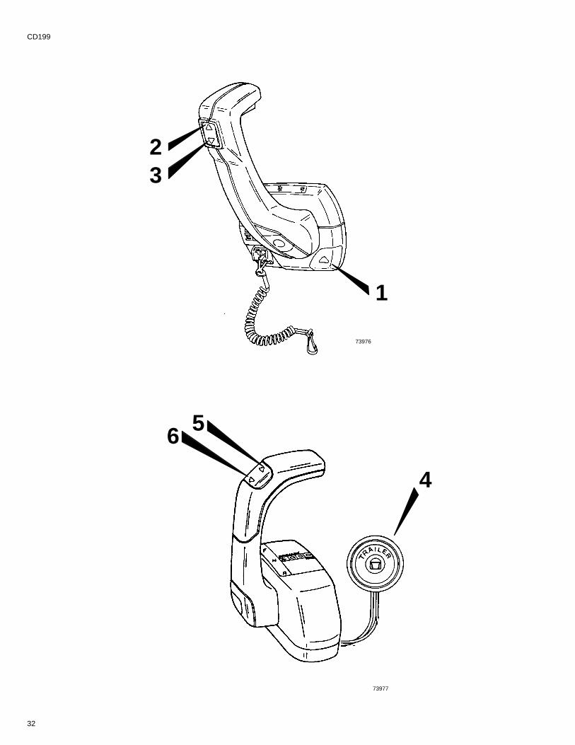
32
CD199
1
32
6
4
5
73976
73977
33
CB188
POWER TRIM OPERATION - PANEL MOUNT REMOTE CONTROL
IMPORTANT: If TRAILER button is held depressed after drive unit reaches end of upward travel, an inter-nal circuit breaker will open and pump will stop. Should this happen, release button and allow motor tocool for about one minute. Circuit breaker will reset and Power Trim operation may be resumed.
1 Trailer Position: Press button until drive unit reaches desired height.
2 Trim Up/Out: Press UP on Trim switch until drive unit reaches desired trim position.
3 Lower Drive Unit: Press DOWN on Trim switch until drive unit reaches desired position.
CB189
POWER TRIM OPERATION - CONSOLE MOUNT REMOTE CONTROL(SINGLE ENGINE VERSION)
4 Trailer Position: Press button until drive unit reaches desired height.
5 Trim Up/Out: Press UP on Trim switch until drive unit reaches desired trim position.
6 Lower Drive Unit: Press DOWN on Trim switch until drive unit reaches desired position.
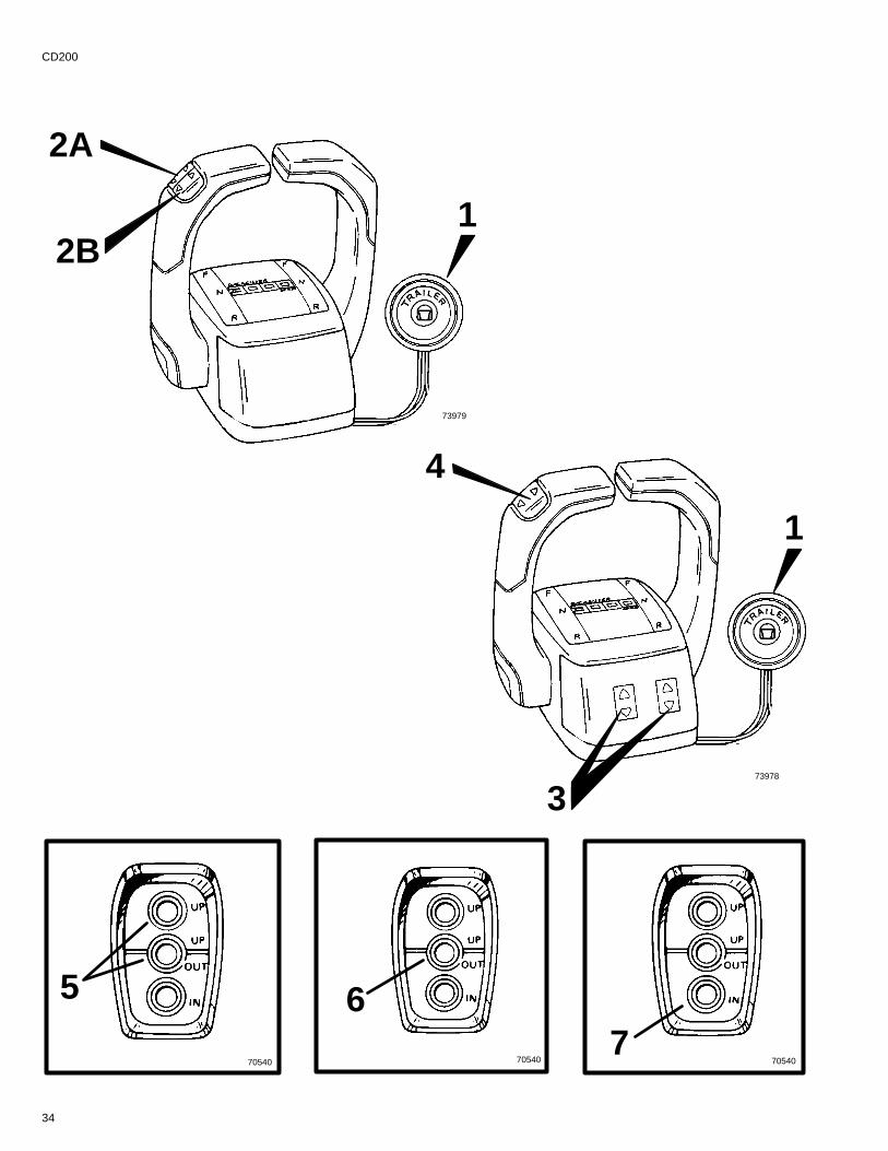
34
CD200
70540 70540 70540
5 67
4
2A
1
12B
373978
73979
35
CB191
POWER TRIM OPERATION - DUAL ENGINE CONSOLE MOUNTREMOTE CONTROL (TWO BUTTON AND THREE BUTTON VERSIONS)
IMPORTANT: If TRAILER button is held depressed after drive unit reaches end of upward travel, an inter-nal circuit breaker will open and pump will stop. Should this happen, release button and allow motor tocool for about one minute. Circuit breaker will reset and Power Trim operation may be resumed.
! CAUTIONWhen lowering or raising stern drives equipped with a dual engine tie bar kit; in the trailering position,stern drives must be lowered evenly to prevent tie bar from becoming twisted. Failure to lower sterndrives evenly may result in tie bar or stern drive(s) damage.
1 Trailer Button (Both Versions) - Press button until drive unit reaches desired height for trailering drive units.
2 Two Button Trim Control (Dual Buttons in Handle) - used to control both drive units from the handle. PressUP on button(s) to trim drive unit UP/OUT. Press down on button(s) to trim drive unit DOWN/IN.
A Forward Trim Button - Used to trim the port drive unit.
B Rear Trim Button - Used to trim the starboard drive unit.
3 Three Button Trim Control (Trim Adjustment Switches) - With a single integral trim button in the handleto control two engines simultaneously, these two switches control the “Fine Tune” adjustment of each engine.Using these “Fine Tune Switches”, set each engine to the desired trim angle. Then use the single trim switchin the handle to control the trim of both engines simultaneously.
4 Three Button Trim Control (Single Trim Switch in Handle) - used to trim both drives simultaneously afterdrives have been fine-tuned as described above.
CB193
POWER TRIM OPERATION - THREE BUTTON TRIM PANEL(USED ON MODELS WITH TWO-LEVER CONTROL)
IMPORTANT: If TRAILER button is held depressed after drive unit reaches end of upward travel, an inter-nal circuit breaker will open and pump will stop. Should this happen, release button(s) and allow motorto cool for about one minute. Circuit breaker will reset and Power Trim operation may be resumed.
5 Trailer Position: Simultaneously press the UP button (top) along with the UP/OUT button (center) until driveunit reaches desired trailer position.
6 Trim Drive Unit UP/OUT: Press center UP/OUT button until drive unit reaches desired trim position.
7 Trim Drive Unit IN/DOWN: Press IN button until drive unit reaches desired trim position.
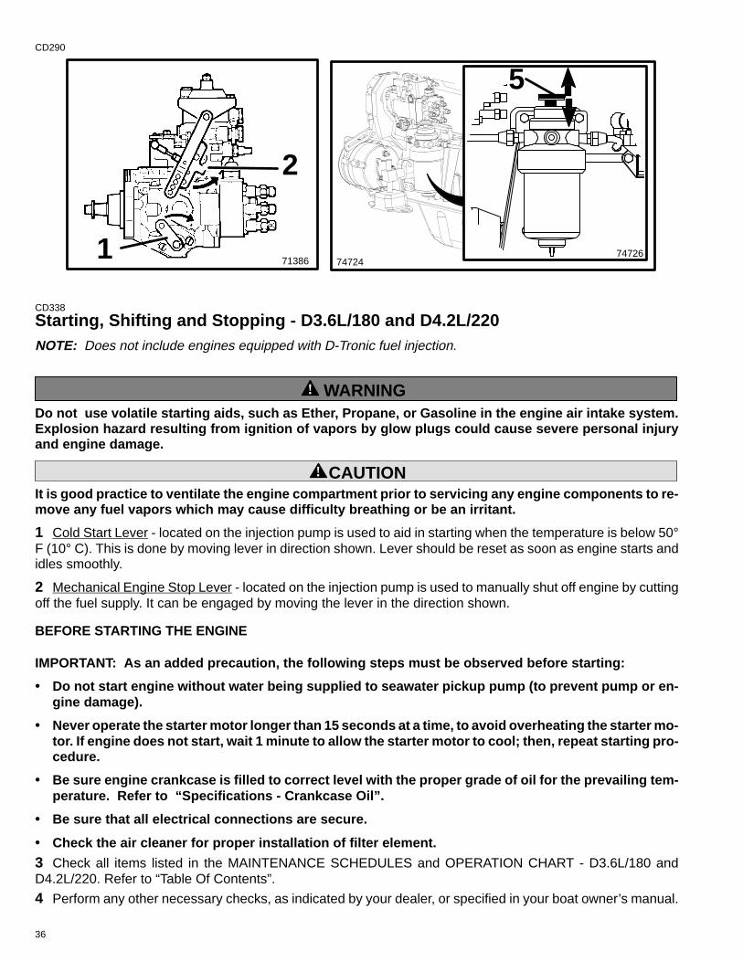
36
CD290
713861 74726
2
74724
5
CD338
Starting, Shifting and Stopping - D3.6L/180 and D4.2L/220NOTE: Does not include engines equipped with D-Tronic fuel injection.
! WARNINGDo not use volatile starting aids, such as Ether, Propane, or Gasoline in the engine air intake system.Explosion hazard resulting from ignition of vapors by glow plugs could cause severe personal injuryand engine damage.
! CAUTIONIt is good practice to ventilate the engine compartment prior to servicing any engine components to re-move any fuel vapors which may cause difficulty breathing or be an irritant.
1 Cold Start Lever - located on the injection pump is used to aid in starting when the temperature is below 50°F (10° C). This is done by moving lever in direction shown. Lever should be reset as soon as engine starts andidles smoothly.
2 Mechanical Engine Stop Lever - located on the injection pump is used to manually shut off engine by cuttingoff the fuel supply. It can be engaged by moving the lever in the direction shown.
BEFORE STARTING THE ENGINE
IMPORTANT: As an added precaution, the following steps must be observed before starting:
• Do not start engine without water being supplied to seawater pickup pump (to prevent pump or en-gine damage).
• Never operate the starter motor longer than 15 seconds at a time, to avoid overheating the starter mo-tor. If engine does not start, wait 1 minute to allow the starter motor to cool; then, repeat starting pro-cedure.
• Be sure engine crankcase is filled to correct level with the proper grade of oil for the prevailing tem-perature. Refer to “Specifications - Crankcase Oil”.
• Be sure that all electrical connections are secure.
• Check the air cleaner for proper installation of filter element.
3 Check all items listed in the MAINTENANCE SCHEDULES and OPERATION CHART - D3.6L/180 andD4.2L/220. Refer to “Table Of Contents”.
4 Perform any other necessary checks, as indicated by your dealer, or specified in your boat owner’s manual.
37
CD339
STARTING COLD ENGINE
IMPORTANT: Always check all fluid levels before starting engine. Refer to Maintenance Chart.
1 Turn on and run engine compartment bilge blower (if so equipped) for five minutes. Or, open engine hatchto air out bilge before attempting to start engine(s).
2 Set “Cold Start Lever” if temperature is below 50° F (10° C).
NOTE: Reset when engine idles smoothly.
3 If engine has not been run for a period of time and will not readily start with the standard starting procedure,there is a hand pump/primer knob located on the fuel filter header. Move knob up and down four or five strokes.
4 Pre-lubricate engine, if required. To do this, hold the “STOP” switch toggle lever DOWN while you simulta-neously turn the key switch to “START” position for 15 seconds. This will rotate the starter motor and engine/oilpump. During this process the engine will not run because no fuel is injected. Allow the starter motor to cool downfor one minute and repeat the above described process. To avoid overheating the starter motor, do not engagestarter motor for more than 15 seconds each time. Refer to “Before Starting the Engine” as previously outlined.
5 Turn key switch to the “RUN” position. Observe indicator lamp for glow plugs. When cylinder temperature isgreat enough to sustain combustion, the indicator lamp will cease to be lighted and the engine can be started.
6 Turn key switch to “START” position and release when engine fires. Check to ensure charge indicator andoil pressure warning lamps go out.
! CAUTIONImproper or no warm-up of engine can seriously impair the Iife of your diesel engine.
7 Run engine at Idle RPM until engine temperature is within normal operating range.
! CAUTIONNever attempt to shift unit unless engine is at idle RPM. Damage to drive unit could occur.
8 Check to ensure all instrumentation is functioning properly and indicating normal readings.
CE31ENGINE WARM UP
! CAUTIONImproper or no warm-up of engine can seriously impair the Iife of your diesel engine.
9 After starting, check to ensure all instrumentation is functioning properly. Run engine at idle RPM until enginetemperature is within normal operating range. It is very important that any engine be warmed up before applyingfull load. The warm-up period provides time for the lubricating oil to establish a film between moving parts.
NOTE: Engine warm-up time during cold weather can be reduced by operating vessel at reduced engine speed.Commence normal vessel operation when systems reach operating temperatures.
10After the engine has reached operating temperature, oil pressure should be within range listed in the enginespecifications chart. Stop the engine if oil pressure is not within this range. Locate and correct the problem, orsee your Authorized MerCruiser Dealer if you are unable to determine the problem.
38
CD340STARTING WARM ENGINE
1 Turn on and run engine compartment bilge blower for five minutes (if so equipped). Or, open engine hatchto air out bilge before attempting to start engine(s).
2 Turn key switch to the “RUN” position.
3 Turn key switch to “START” position and release when engine fires. Check to ensure charge indicator andoil pressure warning lamps go out.
! CAUTIONImproper or no warm-up of engine can seriously impair the Iife of your diesel engine.
4 Check to ensure all instrumentation is functioning properly and indicating normal readings.
CE33SHIFTING
! CAUTIONNever attempt to shift unit unless engine is at idle RPM. Damage to drive unit could occur.
1 To shift unit, be sure remote control/throttle lever is in NEUTRAL. Move control/shift lever with a firm, quickmotion forward to shift to FORWARD gear, or backward to shift to REVERSE. After shifting drive unit, advancethrottle to desired setting.
2 Once underway, engine oil pressure should be within the range listed in the engine specifications chart atmaximum RPM, or Wide-Open-Throttle. Stop the engine if oil pressure is not within this range. Locate and cor-rect the problem, or see your Authorized MerCruiser Dealer if you are unable to determine the problem.
CB575
IMPORTANT: Avoid stopping engine if the drive unit is in gear. If engine does stop with drive unit in gear,refer to the following procedure:
3 Push and pull repeatedly on remote control handle until handle returns to the neutral detent position. This maytake several tries if the power package was operating above idle RPM when the engine stopped.
4 After handle returns to the neutral detent position,resume normal starting procedures.
CD341ENGINE SHUT-DOWN (STOPPING)
5 Place remote control lever in “Neutral.”
! CAUTIONAvoid damaging the turbocharger and engine. Immediate engine shutdown (stopping) after high loadoperation may resulting in permanent turbocharger bearing damage. Operate the engine at IDLE for sev-eral minutes before shut-down.
6 Operate the engine at idle speed for several minutes to allow the turbocharger and engine to cool.
7 Toggle STOP switch “Down” and hold, until engine stops completely.
8 Turn key switch to the “OFF” position.
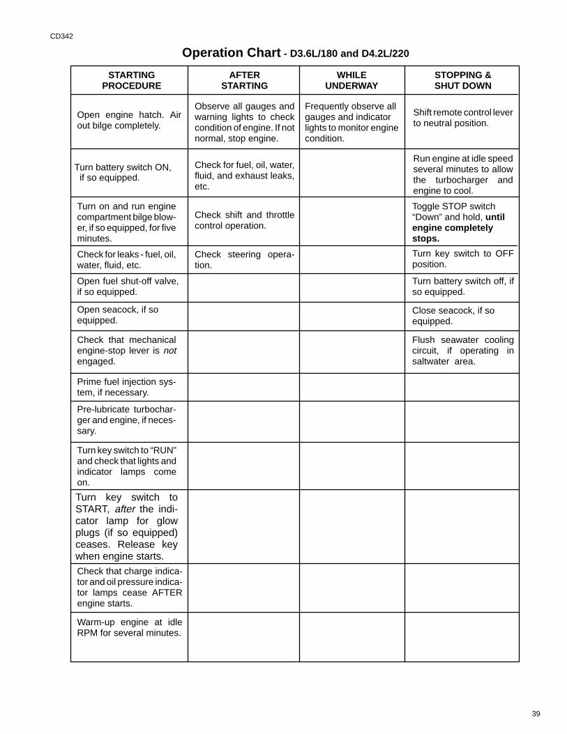
39
CD342
Operation Chart - D3.6L/180 and D4.2L/220
STARTINGPROCEDURE
AFTERSTARTING
WHILEUNDERWAY
STOPPING &SHUT DOWN
Turn on and run enginecompartment bilge blow-er, if so equipped, for fiveminutes.
Observe all gauges andwarning lights to checkcondition of engine. If notnormal, stop engine.
Frequently observe allgauges and indicatorlights to monitor enginecondition.
Shift remote control leverto neutral position.
Check for leaks - fuel, oil,water, fluid, etc.
Check for fuel, oil, water,fluid, and exhaust leaks,etc.
Run engine at idle speedseveral minutes to allowthe turbocharger andengine to cool.
Check that mechanicalengine-stop lever is notengaged.
Check shift and throttlecontrol operation.
Toggle STOP switch“Down” and hold, untilengine completelystops.
Prime fuel injection sys-tem, if necessary.
Turn key switch to OFFposition.
Pre-lubricate turbochar-ger and engine, if neces-sary.
Turn battery switch off, ifso equipped.
Turn key switch to “RUN”and check that lights andindicator lamps comeon.
Close seacock, if soequipped.
Flush seawater coolingcircuit, if operating insaltwater area.
Check that charge indica-tor and oil pressure indica-tor lamps cease AFTERengine starts.
Warm-up engine at idleRPM for several minutes.
Open engine hatch. Airout bilge completely.
Turn battery switch ON, if so equipped.
Open seacock, if soequipped.
Open fuel shut-off valve,if so equipped.
Check steering opera-tion.
Turn key switch toSTART, after the indi-cator lamp for glowplugs (if so equipped)ceases. Release keywhen engine starts.
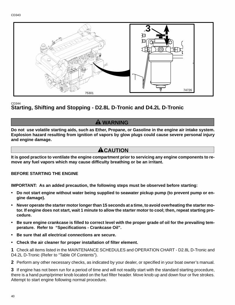
40
CD343
7472675301
3
CD344
Starting, Shifting and Stopping - D2.8L D-Tronic and D4.2L D-Tronic
! WARNINGDo not use volatile starting aids, such as Ether, Propane, or Gasoline in the engine air intake system.Explosion hazard resulting from ignition of vapors by glow plugs could cause severe personal injuryand engine damage.
! CAUTIONIt is good practice to ventilate the engine compartment prior to servicing any engine components to re-move any fuel vapors which may cause difficulty breathing or be an irritant.
BEFORE STARTING THE ENGINE
IMPORTANT: As an added precaution, the following steps must be observed before starting:
• Do not start engine without water being supplied to seawater pickup pump (to prevent pump or en-gine damage).
• Never operate the starter motor longer than 15 seconds at a time, to avoid overheating the starter mo-tor. If engine does not start, wait 1 minute to allow the starter motor to cool; then, repeat starting pro-cedure.
• Be sure engine crankcase is filled to correct level with the proper grade of oil for the prevailing tem-perature. Refer to “Specifications - Crankcase Oil”.
• Be sure that all electrical connections are secure.
• Check the air cleaner for proper installation of filter element.
1 Check all items listed in the MAINTENANCE SCHEDULES and OPERATION CHART - D2.8L D-Tronic andD4.2L D-Tronic (Refer to “Table Of Contents”).
2 Perform any other necessary checks, as indicated by your dealer, or specified in your boat owner’s manual.
3 If engine has not been run for a period of time and will not readily start with the standard starting procedure,there is a hand pump/primer knob located on the fuel filter header. Move knob up and down four or five strokes.Attempt to start engine following normal procedure.
41
CD345STARTING COLD ENGINE
IMPORTANT: Always check all fluid levels before starting engine. Refer to Maintenance Chart.1 Turn on and run engine compartment bilge blower (if so equipped) for five minutes. Or, open engine hatchto air out bilge before attempting to start engine(s).
2 Turn key switch to the “RUN” position. Observe indicator lamp for glow plugs, if so equipped. When cylindertemperature is great enough to sustain combustion, the indicator lamp will cease to be lighted and the enginecan be started.
3 Turn key switch to START position. Release key when engine starts and allow switch to return to RUN posi-tion.
4 Check to ensure all instrumentation is functioning properly and indicating normal readings. Check to ensurecharge indicator and oil pressure warning lamps go out. Within seconds after starting the engine, oil pressureshould exceed 10 psi (69 kPa) minimum. If the oil pressure does not meet these minimum limits, stop the engine,locate and correct the problem, or see your Authorized MerCruiser Dealer if you are unable to determine theproblem.
! CAUTIONDo not increase the engine speed until the oil pressure gauge indicates normal. Shut the engine downif oil pressure does not register on the gauge within 20 to 30 seconds after start.
CE31ENGINE WARM UP
! CAUTIONImproper or no warm-up of engine can seriously impair the Iife of your diesel engine.1 After starting, check to ensure all instrumentation is functioning properly. Run engine at idle RPM until enginetemperature is within normal operating range. It is very important that any engine be warmed up before applyingfull load. The warm-up period provides time for the lubricating oil to establish a film between moving parts.
NOTE: Engine warm-up time during cold weather can be reduced by operating vessel at reduced engine speed.Commence normal vessel operation when systems reach operating temperatures.
2 After the engine has reached operating temperature, oil pressure should be within range listed in the enginespecifications chart. Stop the engine if oil pressure is not within this range. Locate and correct the problem, orsee your Authorized MerCruiser Dealer if you are unable to determine the problem.
42
CE32STARTING WARM ENGINE
1 Turn on and run engine compartment bilge blower for five minutes (if so equipped). Or, open engine hatchto air out bilge before attempting to start engine(s).
2 Turn key switch to the “RUN” position. Check to ensure glow plug preheat lamp is not illuminated.
3 Turn key switch to the “START” position and release when engine fires. Check to ensure charge indicator andoil pressure warning lamps go out.
4 Check to ensure all instrumentation is functioning properly and indicating normal readings. Oil pressureshould be within the range listed in the engine specifications chart. Stop the engine if oil pressure is not withinthis range. Locate and correct the problem, or see your Authorized MerCruiser Dealer if you are unable to deter-mine the problem.
CE33SHIFTING
! CAUTIONNever attempt to shift unit unless engine is at idle RPM. Damage to drive unit could occur.
5 To shift unit, be sure remote control/throttle lever is in NEUTRAL. Move control/shift lever with a firm, quickmotion forward to shift to FORWARD gear, or backward to shift to REVERSE. After shifting drive unit, advancethrottle to desired setting.
6 Once underway, engine oil pressure should be within the range listed in the engine specifications chart atmaximum RPM, or Wide-Open-Throttle. Stop the engine if oil pressure is not within this range. Locate and cor-rect the problem, or see your Authorized MerCruiser Dealer if you are unable to determine the problem.
CB575
IMPORTANT: Avoid stopping engine if the drive unit is in gear. If engine does stop with drive unit in gear,refer to the following procedure:
7 Push and pull repeatedly on remote control handle until handle returns to the neutral detent position. This maytake several tries if the power package was operating above idle RPM when the engine stopped.
8 After handle returns to the neutral detent position,resume normal starting procedures.
CD366ENGINE SHUT-DOWN (STOPPING)
9 Place remote control lever in “Neutral.”
! CAUTIONAvoid damaging the turbocharger and engine. Immediate engine shutdown (stopping) after high loadoperation may resulting in permanent turbocharger bearing damage. Operate the engine at IDLE for sev-eral minutes before shut-down.
10Operate the engine at idle speed for several minutes to allow the turbocharger and engine to cool.
11 Turn key switch to the “OFF” position.
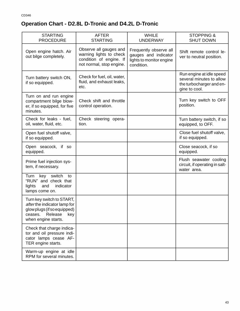
43
CD346
Operation Chart - D2.8L D-Tronic and D4.2L D-Tronic
STARTINGPROCEDURE
AFTERSTARTING
WHILEUNDERWAY
STOPPING &SHUT DOWN
Turn on and run enginecompartment bilge blow-er, if so equipped, for fiveminutes.
Observe all gauges andwarning lights to checkcondition of engine. Ifnot normal, stop engine.
Frequently observe allgauges and indicatorlights to monitor enginecondition.
Shift remote control le-ver to neutral position.
Check for leaks - fuel,oil, water, fluid, etc.
Check for fuel, oil, water,fluid, and exhaust leaks,etc.
Run engine at idle speedseveral minutes to allowthe turbocharger and en-gine to cool.
Check shift and throttlecontrol operation.
Prime fuel injection sys-tem, if necessary.
Turn key switch to OFFposition.
Turn battery switch, if soequipped, to OFF.
Turn key switch to“RUN” and check thatlights and indicatorlamps come on.
Close seacock, if soequipped.
Turn key switch to START,after the indicator lamp forglow plugs (if so equipped)ceases. Release keywhen engine starts.
Flush seawater coolingcircuit, if operating in salt-water area.
Check that charge indica-tor and oil pressure indi-cator lamps cease AF-TER engine starts.
Warm-up engine at idleRPM for several minutes.
Open seacock, if soequipped.
Open fuel shutoff valve,if so equipped.
Open engine hatch. Airout bilge completely.
Turn battery switch ON,if so equipped.
Check steering opera-tion.
Close fuel shutoff valve,if so equipped.
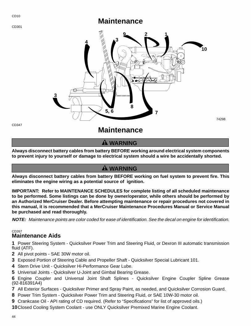
44
CD10
MaintenanceCD301
2
3
8
9 13
10
75, 6
4
74298
CD347
Maintenance
! WARNINGAlways disconnect battery cables from battery BEFORE working around electrical system componentsto prevent injury to yourself or damage to electrical system should a wire be accidentally shorted.
! WARNINGAlways disconnect battery cables from battery BEFORE working on fuel system to prevent fire. Thiseliminates the engine wiring as a potential source of ignition.
IMPORTANT: Refer to MAINTENANCE SCHEDULES for complete listing of all scheduled maintenanceto be performed. Some listings can be done by owner/operator, while others should be performed byan Authorized MerCruiser Dealer. Before attempting maintenance or repair procedures not covered inthis manual, it is recommended that a MerCruiser Maintenance Procedures Manual or Service Manualbe purchased and read thoroughly.
NOTE: Maintenance points are color coded for ease of identification. See the decal on engine for identification.
CD267
Maintenance Aids1 Power Steering System - Quicksilver Power Trim and Steering Fluid, or Dexron III automatic transmissionfluid (ATF).2 All pivot points - SAE 30W motor oil.3 Exposed Portion of Steering Cable and Propeller Shaft - Quicksilver Special Lubricant 101.4 Stern Drive Unit - Quicksilver Hi-Performance Gear Lube.5 Universal Joints - Quicksilver U-Joint and Gimbal Bearing Grease.6 Engine Coupler and Universal Joint Shaft Splines - Quicksilver Engine Coupler Spline Grease(92-816391A4)7 All Exterior Surfaces - Quicksilver Primer and Spray Paint, as needed, and Quicksilver Corrosion Guard.8 Power Trim System - Quicksilver Power Trim and Steering Fluid, or SAE 10W-30 motor oil.9 Crankcase Oil - API rating of CD required. (Refer to “Specifications” for list of approved oils.)10Closed Cooling System Coolant - use ONLY Quicksilver Premixed Marine Engine Coolant.
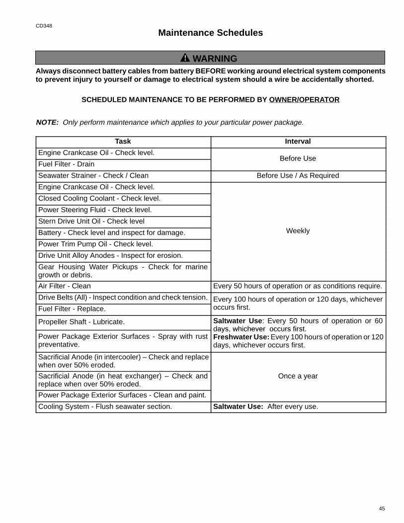
45
CD348
Maintenance Schedules
! WARNINGAlways disconnect battery cables from battery BEFORE working around electrical system componentsto prevent injury to yourself or damage to electrical system should a wire be accidentally shorted.
SCHEDULED MAINTENANCE TO BE PERFORMED BY OWNER/OPERATOR
NOTE: Only perform maintenance which applies to your particular power package.
Task Interval
Engine Crankcase Oil - Check level.Before Use
Fuel Filter - DrainBefore Use
Seawater Strainer - Check / Clean Before Use / As Required
Engine Crankcase Oil - Check level.
W kl
Closed Cooling Coolant - Check level.
W kl
Power Steering Fluid - Check level.
W klStern Drive Unit Oil - Check level
W klBattery - Check level and inspect for damage. Weekly
Power Trim Pump Oil - Check level.
Drive Unit Alloy Anodes - Inspect for erosion.
Gear Housing Water Pickups - Check for marinegrowth or debris.
Air Filter - Clean Every 50 hours of operation or as conditions require.
Drive Belts (All) - Inspect condition and check tension. Every 100 hours of operation or 120 days, whicheverfFuel Filter - Replace.
y p y ,occurs first.
Propeller Shaft - Lubricate. Saltwater Use : Every 50 hours of operation or 60days, whichever occurs first.
Power Package Exterior Surfaces - Spray with rustpreventative.
days, whichever occurs first.Freshwater Use: Every 100 hours of operation or 120days, whichever occurs first.
Sacrificial Anode (in intercooler) – Check and replacewhen over 50% eroded.
OSacrificial Anode (in heat exchanger) – Check andreplace when over 50% eroded.
Once a year
Power Package Exterior Surfaces - Clean and paint.
Cooling System - Flush seawater section. Saltwater Use: After every use.
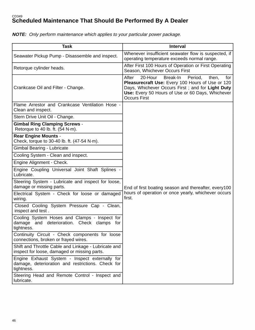
46
CD349
Scheduled Maintenance That Should Be Performed By A Dealer
NOTE: Only perform maintenance which applies to your particular power package.
Task Interval
Seawater Pickup Pump - Disassemble and inspect. Whenever insufficient seawater flow is suspected, ifoperating temperature exceeds normal range.
Retorque cylinder heads. After First 100 Hours of Operation or First OperatingSeason, Whichever Occurs First
Crankcase Oil and Filter - Change.
After 20-Hour Break-In Period, then, forPleasurecraft Use: Every 100 Hours of Use or 120Days, Whichever Occurs First ; and for Light DutyUse: Every 50 Hours of Use or 60 Days, WhicheverOccurs First
Flame Arrestor and Crankcase Ventilation Hose -Clean and inspect.
E d f fi b i d h f
Stern Drive Unit Oil - Change.
E d f fi b i d h f
Gimbal Ring Clamping Screws - Retorque to 40 lb. ft. (54 N·m).
E d f fi b i d h f
Rear Engine Mounts - Check, torque to 30-40 lb. ft. (47-54 N·m).
E d f fi b i d h f
Gimbal Bearing - Lubricate
E d f fi b i d h f
Cooling System - Clean and inspect.
E d f fi b i d h f
Engine Alignment - Check.
E d f fi b i d h f
Engine Coupling Universal Joint Shaft Splines -Lubricate.
E d f fi b i d h fSteering System - Lubricate and inspect for loose,damage or missing parts. End of first boating season and thereafter, every100
fElectrical System - Check for loose or damagedwiring.
g , yhours of operation or once yearly, whichever occursfirst.
Closed Cooling System Pressure Cap - Clean,inspect and test .
Cooling System Hoses and Clamps - Inspect fordamage and deterioration. Check clamps fortightness.
Continuity Circuit - Check components for looseconnections, broken or frayed wires.
Shift and Throttle Cable and Linkage - Lubricate andinspect for loose, damaged or missing parts.
Engine Exhaust System - Inspect externally fordamage, deterioration and restrictions. Check fortightness.
Steering Head and Remote Control - Inspect andlubricate.
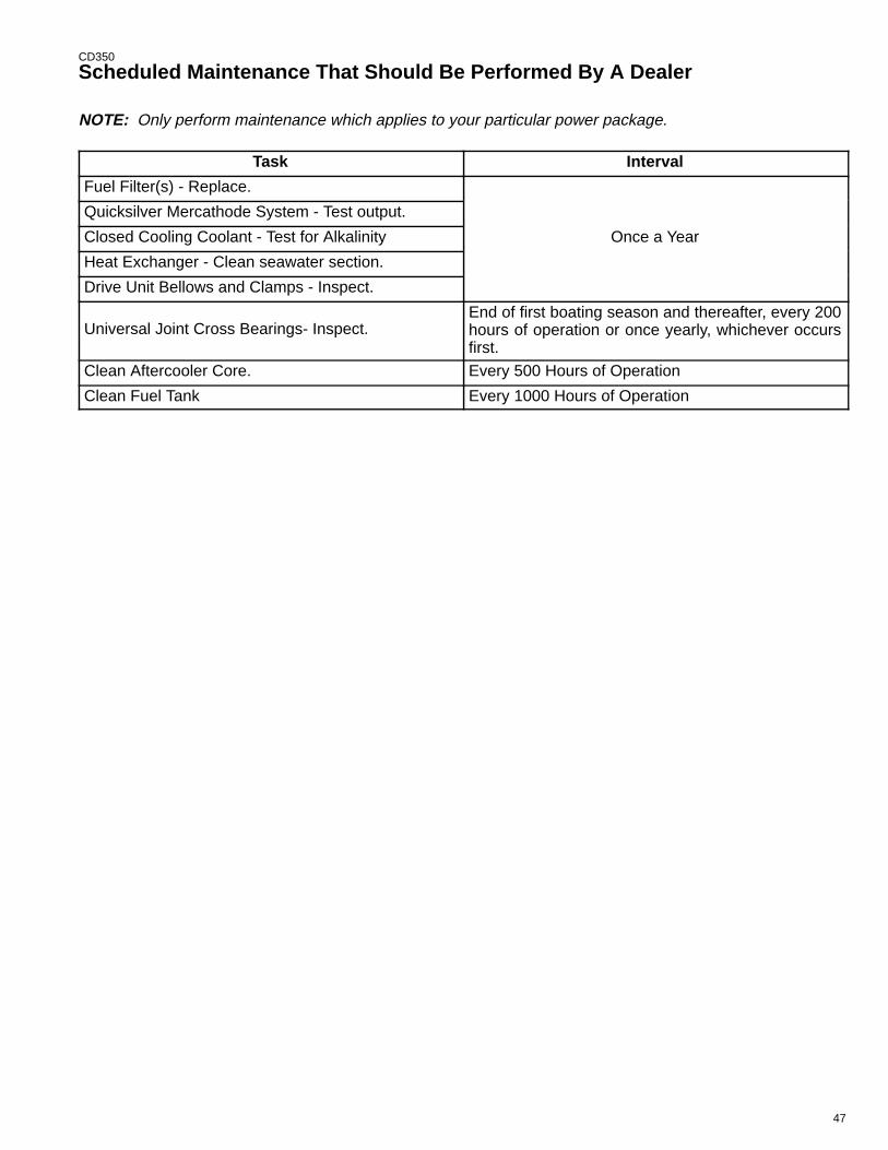
47
CD350
Scheduled Maintenance That Should Be Performed By A Dealer
NOTE: Only perform maintenance which applies to your particular power package.
Task Interval
Fuel Filter(s) - Replace.
O Y
Quicksilver Mercathode System - Test output.
O YClosed Cooling Coolant - Test for Alkalinity Once a Year
Heat Exchanger - Clean seawater section.
Drive Unit Bellows and Clamps - Inspect.
Universal Joint Cross Bearings- Inspect.End of first boating season and thereafter, every 200hours of operation or once yearly, whichever occursfirst.
Clean Aftercooler Core. Every 500 Hours of Operation
Clean Fuel Tank Every 1000 Hours of Operation
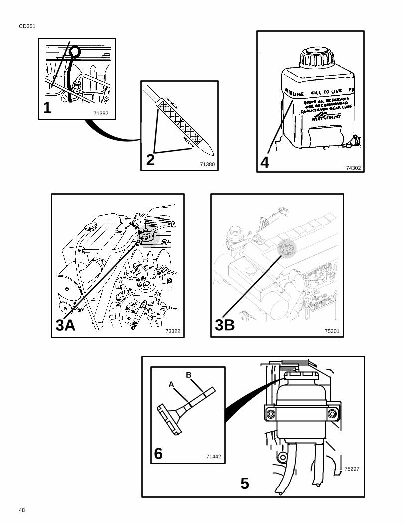
48
CD351
74302
733223A
4
713821
713802
5
71442
AB
675297
753013B
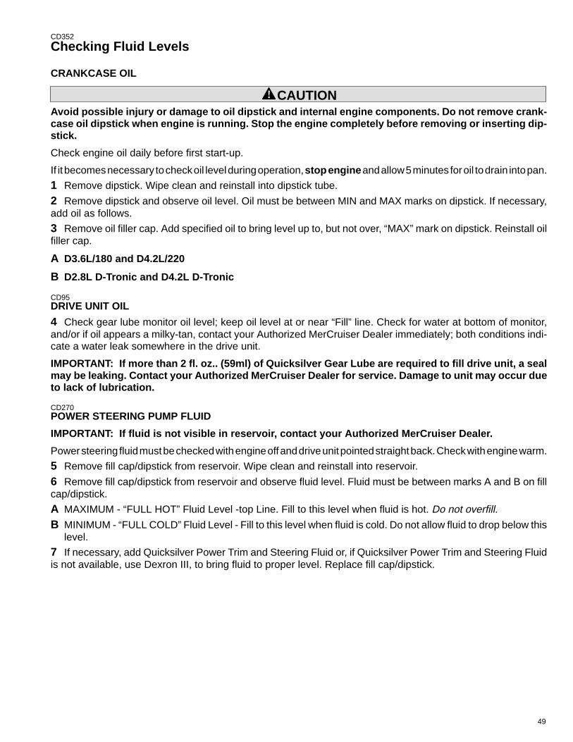
49
CD352
Checking Fluid Levels
CRANKCASE OIL
! CAUTIONAvoid possible injury or damage to oil dipstick and internal engine components. Do not remove crank-case oil dipstick when engine is running. Stop the engine completely before removing or inserting dip-stick.
Check engine oil daily before first start-up.
If it becomes necessary to check oil level during operation, stop engine and allow 5 minutes for oil to drain into pan.
1 Remove dipstick. Wipe clean and reinstall into dipstick tube.
2 Remove dipstick and observe oil level. Oil must be between MIN and MAX marks on dipstick. If necessary,add oil as follows.
3 Remove oil filler cap. Add specified oil to bring level up to, but not over, “MAX” mark on dipstick. Reinstall oilfiller cap.
A D3.6L/180 and D4.2L/220
B D2.8L D-Tronic and D4.2L D-Tronic
CD95DRIVE UNIT OIL
4 Check gear lube monitor oil level; keep oil level at or near “Fill” line. Check for water at bottom of monitor,and/or if oil appears a milky-tan, contact your Authorized MerCruiser Dealer immediately; both conditions indi-cate a water leak somewhere in the drive unit.
IMPORTANT: If more than 2 fl. oz.. (59ml) of Quicksilver Gear Lube are required to fill drive unit, a sealmay be leaking. Contact your Authorized MerCruiser Dealer for service. Damage to unit may occur dueto lack of lubrication.
CD270POWER STEERING PUMP FLUID
IMPORTANT: If fluid is not visible in reservoir, contact your Authorized MerCruiser Dealer.
Power steering fluid must be checked with engine off and drive unit pointed straight back. Check with engine warm.
5 Remove fill cap/dipstick from reservoir. Wipe clean and reinstall into reservoir.
6 Remove fill cap/dipstick from reservoir and observe fluid level. Fluid must be between marks A and B on fillcap/dipstick.
A MAXIMUM - “FULL HOT” Fluid Level -top Line. Fill to this level when fluid is hot. Do not overfill.
B MINIMUM - “FULL COLD” Fluid Level - Fill to this level when fluid is cold. Do not allow fluid to drop below thislevel.
7 If necessary, add Quicksilver Power Trim and Steering Fluid or, if Quicksilver Power Trim and Steering Fluidis not available, use Dexron III, to bring fluid to proper level. Replace fill cap/dipstick.
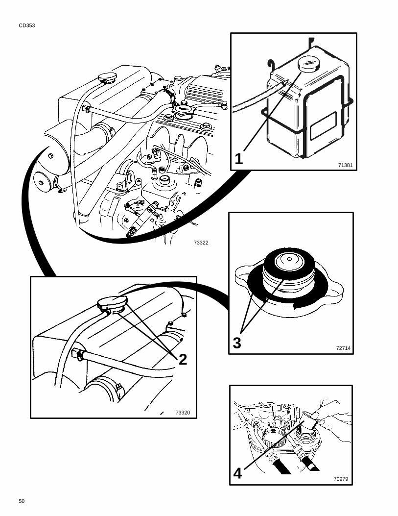
713811
2
73320
3 72714
73322
709794
50
CD353
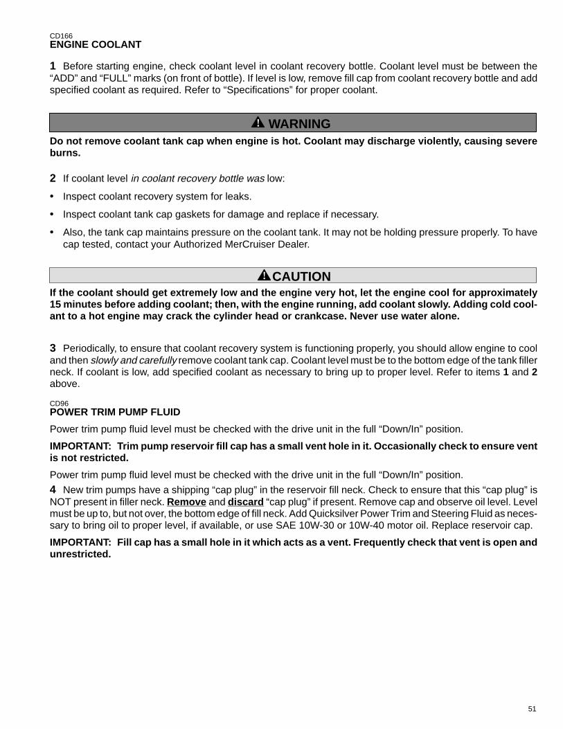
51
CD166ENGINE COOLANT
1 Before starting engine, check coolant level in coolant recovery bottle. Coolant level must be between the“ADD” and “FULL” marks (on front of bottle). If level is low, remove fill cap from coolant recovery bottle and addspecified coolant as required. Refer to “Specifications” for proper coolant.
! WARNINGDo not remove coolant tank cap when engine is hot. Coolant may discharge violently, causing severeburns.
2 If coolant level in coolant recovery bottle was low:
• Inspect coolant recovery system for leaks.
• Inspect coolant tank cap gaskets for damage and replace if necessary.
• Also, the tank cap maintains pressure on the coolant tank. It may not be holding pressure properly. To havecap tested, contact your Authorized MerCruiser Dealer.
! CAUTIONIf the coolant should get extremely low and the engine very hot, let the engine cool for approximately15 minutes before adding coolant; then, with the engine running, add coolant slowly. Adding cold cool-ant to a hot engine may crack the cylinder head or crankcase. Never use water alone.
3 Periodically, to ensure that coolant recovery system is functioning properly, you should allow engine to cooland then slowly and carefully remove coolant tank cap. Coolant level must be to the bottom edge of the tank fillerneck. If coolant is low, add specified coolant as necessary to bring up to proper level. Refer to items 1 and 2above.
CD96POWER TRIM PUMP FLUID
Power trim pump fluid level must be checked with the drive unit in the full “Down/In” position.
IMPORTANT: Trim pump reservoir fill cap has a small vent hole in it. Occasionally check to ensure ventis not restricted.
Power trim pump fluid level must be checked with the drive unit in the full “Down/In” position.
4 New trim pumps have a shipping “cap plug” in the reservoir fill neck. Check to ensure that this “cap plug” isNOT present in filler neck. Remove and discard “cap plug” if present. Remove cap and observe oil level. Levelmust be up to, but not over, the bottom edge of fill neck. Add Quicksilver Power Trim and Steering Fluid as neces-sary to bring oil to proper level, if available, or use SAE 10W-30 or 10W-40 motor oil. Replace reservoir cap.
IMPORTANT: Fill cap has a small hole in it which acts as a vent. Frequently check that vent is open andunrestricted.
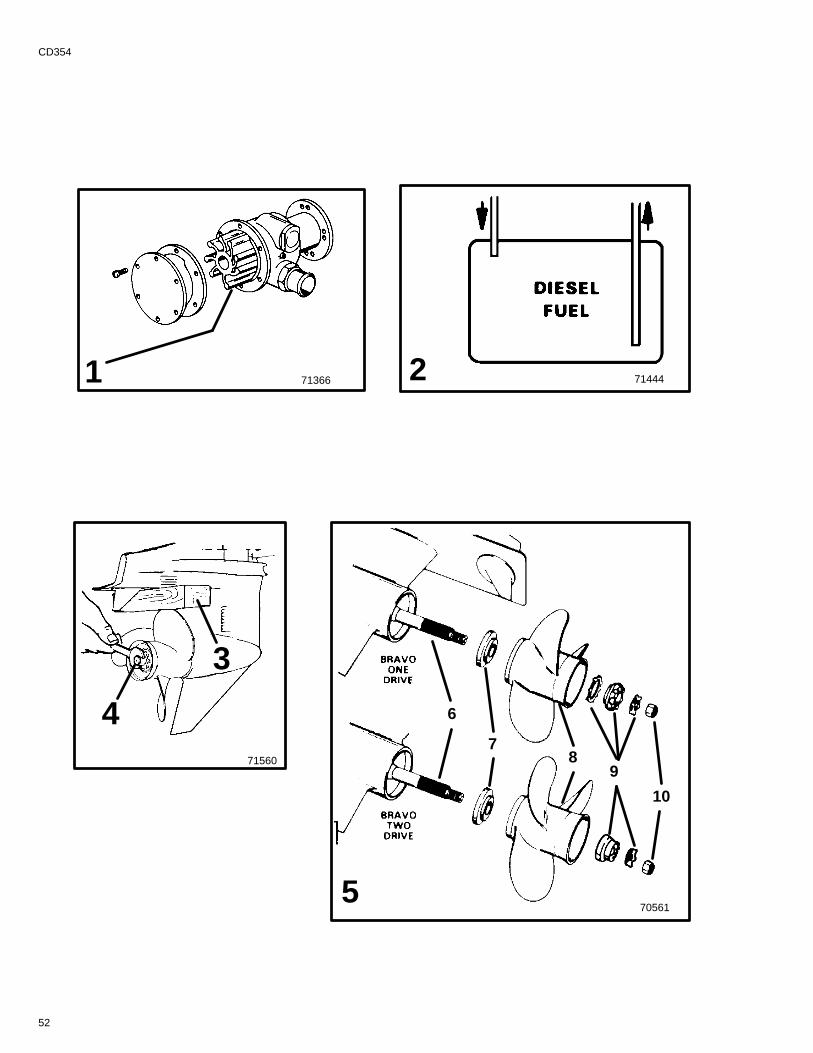
52
CD354
705615
6
78
9
10
71560
3
4
71366 7144421
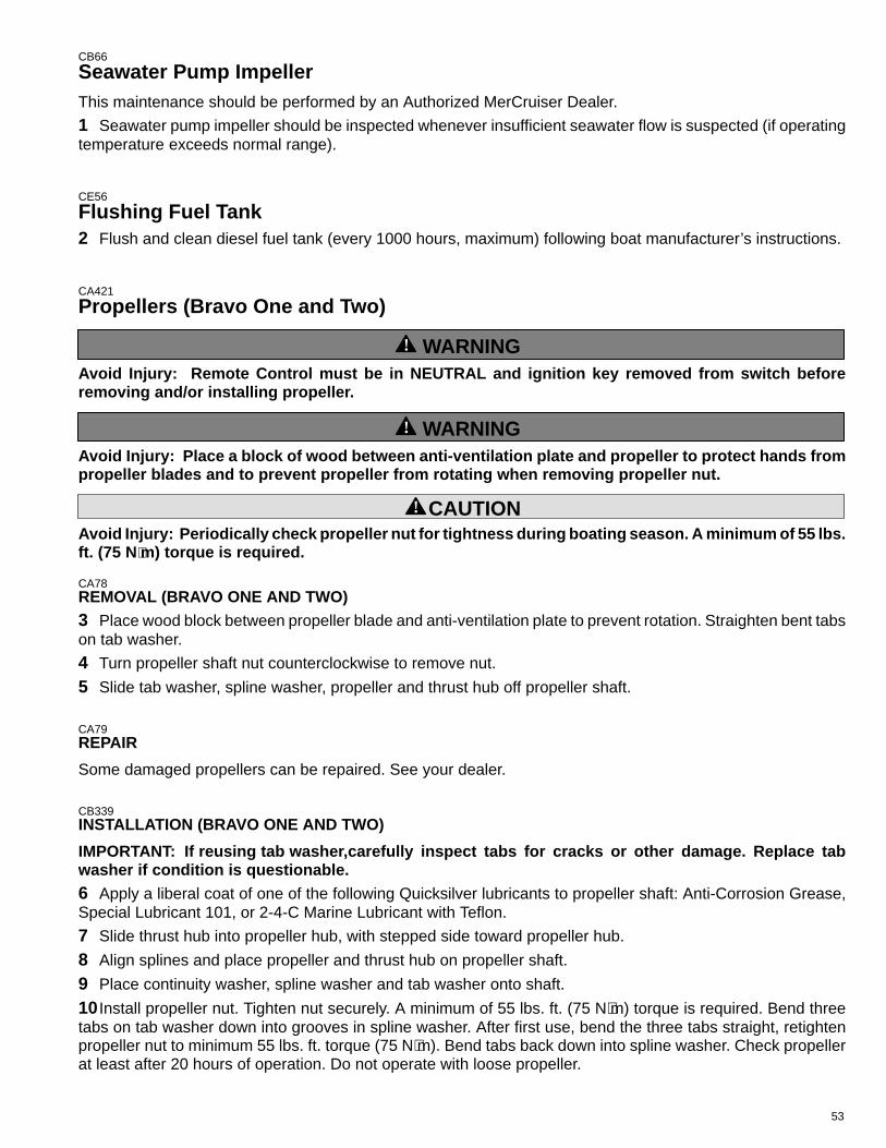
53
CB66
Seawater Pump ImpellerThis maintenance should be performed by an Authorized MerCruiser Dealer.
1 Seawater pump impeller should be inspected whenever insufficient seawater flow is suspected (if operatingtemperature exceeds normal range).
CE56
Flushing Fuel Tank2 Flush and clean diesel fuel tank (every 1000 hours, maximum) following boat manufacturer’s instructions.
CA421
Propellers (Bravo One and Two)
! WARNINGAvoid Injury: Remote Control must be in NEUTRAL and ignition key removed from switch beforeremoving and/or installing propeller.
! WARNINGAvoid Injury: Place a block of wood between anti-ventilation plate and propeller to protect hands frompropeller blades and to prevent propeller from rotating when removing propeller nut.
! CAUTIONAvoid Injury: Periodically check propeller nut for tightness during boating season. A minimum of 55 lbs.ft. (75 N ⋅m) torque is required.
CA78REMOVAL (BRAVO ONE AND TWO)3 Place wood block between propeller blade and anti-ventilation plate to prevent rotation. Straighten bent tabson tab washer.
4 Turn propeller shaft nut counterclockwise to remove nut.
5 Slide tab washer, spline washer, propeller and thrust hub off propeller shaft.
CA79REPAIR
Some damaged propellers can be repaired. See your dealer.
CB339INSTALLATION (BRAVO ONE AND TWO)
IMPORTANT: If reusing tab washer,carefully inspect tabs for cracks or other damage. Replace tabwasher if condition is questionable.6 Apply a liberal coat of one of the following Quicksilver lubricants to propeller shaft: Anti-Corrosion Grease,Special Lubricant 101, or 2-4-C Marine Lubricant with Teflon.
7 Slide thrust hub into propeller hub, with stepped side toward propeller hub.
8 Align splines and place propeller and thrust hub on propeller shaft.
9 Place continuity washer, spline washer and tab washer onto shaft.
10 Install propeller nut. Tighten nut securely. A minimum of 55 lbs. ft. (75 N⋅m) torque is required. Bend threetabs on tab washer down into grooves in spline washer. After first use, bend the three tabs straight, retightenpropeller nut to minimum 55 lbs. ft. torque (75 N⋅m). Bend tabs back down into spline washer. Check propellerat least after 20 hours of operation. Do not operate with loose propeller.
54
CD355
6
7
910
12
72239
11
8
4
72239
2
55
CD356
Propellers (Bravo Three)
! WARNINGAvoid Injury: Remote Control must be in NEUTRAL and ignition key removed from switch beforeremoving and/or installing propellers.
! WARNINGAvoid Injury: Place a block of wood between splash-plate and propellers to protect hands from propellerblades and to prevent propellers from rotating when removing propeller nuts.
! CAUTIONAvoid Injury: Do not operate with loose propeller. Periodically check propeller nuts for tightness duringboating season.
REMOVAL (BRAVO THREE)
1 Place wood block between propeller blades and anti-ventilation plate to prevent rotation.
2 Turn aft propeller shaft nut counterclockwise to remove nut.
3 Slide propeller and thrust hub off propeller shaft.
4 Turn front propeller shaft nut counterclockwise to remove nut.
5 Slide propeller and thrust hub off propeller shaft.
CA79REPAIR
Some damaged propellers can be repaired. See your dealer.
CB345INSTALLATION (BRAVO THREE)
6 Apply a liberal coat of one of the following Quicksilver lubricants to both propeller shafts: Special Lubricant101, 2-4-C Marine Lubricant with Teflon, or Anti-Corrosion Grease.
7 Slide forward thrust hub onto propeller shaft, with tapered side toward propeller hub (toward end of shaft).
8 Align splines and place propeller on propeller shaft.
9 Install propeller nut. Tighten nut securely. A minimum of 100 lbs. ft. (136 N·m) torque is required. Check pro-peller at least after 20 hours of operation. Do not operate with loose propeller.
10Slide aft thrust hub onto propeller shaft, with tapered side toward propeller hub (toward end of shaft).
11 Align splines and place propeller on propeller shaft.
12 Install propeller nut. Tighten nut securely. A minimum of 60 lbs. ft. (81 N·m) torque is required. Check propellerat least after 20 hours of operation. Do not operate with loose propeller.
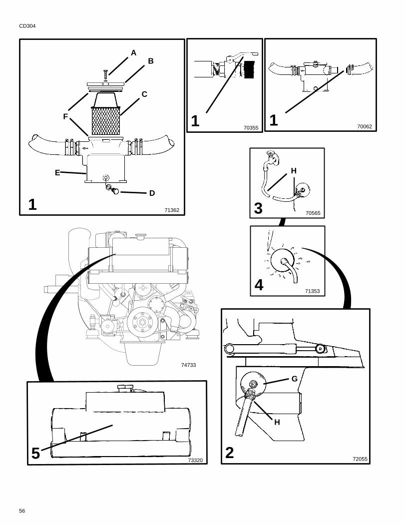
56
CD304
71362 1
5 2 72055
70565
713534
3
73320
74733
AB
C
D
E
F
G
H
H
170355 700621
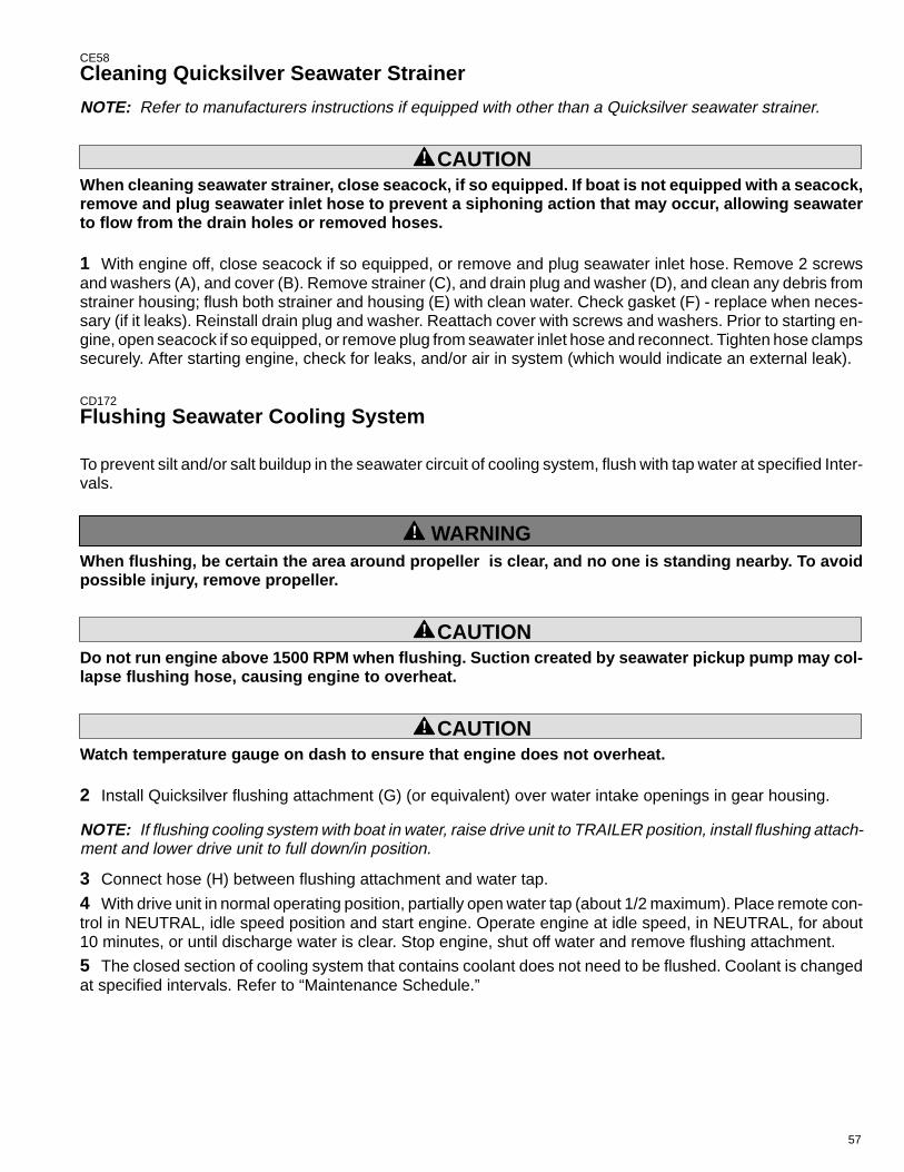
57
CE58
Cleaning Quicksilver Seawater Strainer
NOTE: Refer to manufacturers instructions if equipped with other than a Quicksilver seawater strainer.
! CAUTIONWhen cleaning seawater strainer, close seacock, if so equipped. If boat is not equipped with a seacock,remove and plug seawater inlet hose to prevent a siphoning action that may occur, allowing seawaterto flow from the drain holes or removed hoses.
1 With engine off, close seacock if so equipped, or remove and plug seawater inlet hose. Remove 2 screwsand washers (A), and cover (B). Remove strainer (C), and drain plug and washer (D), and clean any debris fromstrainer housing; flush both strainer and housing (E) with clean water. Check gasket (F) - replace when neces-sary (if it leaks). Reinstall drain plug and washer. Reattach cover with screws and washers. Prior to starting en-gine, open seacock if so equipped, or remove plug from seawater inlet hose and reconnect. Tighten hose clampssecurely. After starting engine, check for leaks, and/or air in system (which would indicate an external leak).
CD172
Flushing Seawater Cooling System
To prevent silt and/or salt buildup in the seawater circuit of cooling system, flush with tap water at specified Inter-vals.
! WARNINGWhen flushing, be certain the area around propeller is clear, and no one is standing nearby. To avoidpossible injury, remove propeller.
! CAUTIONDo not run engine above 1500 RPM when flushing. Suction created by seawater pickup pump may col-lapse flushing hose, causing engine to overheat.
! CAUTIONWatch temperature gauge on dash to ensure that engine does not overheat.
2 Install Quicksilver flushing attachment (G) (or equivalent) over water intake openings in gear housing.
NOTE: If flushing cooling system with boat in water, raise drive unit to TRAILER position, install flushing attach-ment and lower drive unit to full down/in position.
3 Connect hose (H) between flushing attachment and water tap.
4 With drive unit in normal operating position, partially open water tap (about 1/2 maximum). Place remote con-trol in NEUTRAL, idle speed position and start engine. Operate engine at idle speed, in NEUTRAL, for about10 minutes, or until discharge water is clear. Stop engine, shut off water and remove flushing attachment.
5 The closed section of cooling system that contains coolant does not need to be flushed. Coolant is changedat specified intervals. Refer to “Maintenance Schedule.”
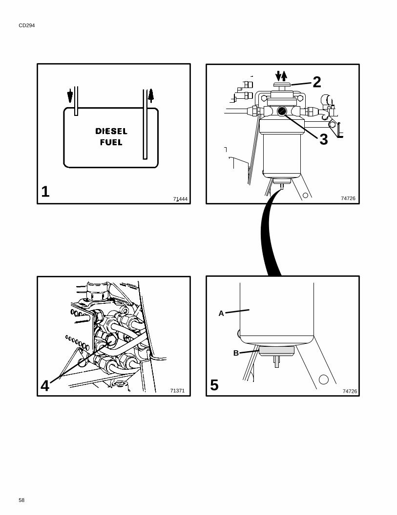
58
CD294
74726
71371
714441
2
3
4
B
A
5 74726

59
CE61
Fuel System
! CAUTIONAbsolute cleanliness is required for work on the fuel system, since the injection pump and fuel injectorshave very close tolerances. Even minute particles of dirt or small amounts of water can impair the func-tion of the fuel injection system.
FUEL TANK
IMPORTANT: Diesel fuel should not be left in tank during winter storage, as an accumulation of rust,sludge and wax residue will form.1 Fuel tank should be cleaned at specified intervals. Refer to boat manufacturer’s instructions.
CD283HAND PUMP/PRIMER2 A plunger-type of hand pump/primer is located on the fuel filter bracket and is used to: (1) refill fuel systemif system was run dry; (2) refill fuel filter when changing filter; or (3) to prime the fuel system if engine has notbeen run for a while.To operate the hand pump/primer, move the plunger (upper portion) up and down as needed.
CE63PRIMING FUEL SYSTEM
Prime engine if it has not been run for a while or if engine will not start. Move the hand pump/primer plunger upand down several times as previously outlined. Attempt to start engine.
CD284FILLING FUEL FILTER
NOTE: Follow this procedure after installing new filter or if fuel has been drained from filter checking for water.
3 Loosen bleed screw on fuel filter bracket. As previously outlined, move plunger on hand pump/primer up anddown repeatedly, until an air free stream of fuel flows from bleed screw. Filter is full when this occurs. Tightenbleed screw.
CD285FILLING (BLEEDING) FUEL SYSTEM
NOTE: Follow this procedure if fuel system was run dry or if part of fuel system was drained for a service function.
Fill fuel system up to the point that fuel filter is full following previous procedure (Filling Fuel Filter); then, ensurethat bleed screw on fuel filter bracket is closed.
4 Loosen, DO NOT REMOVE, bleed screw on fuel injection pump (located between fuel line connection fittingson injection pump). Continue to repeatedly move plunger on hand pump/primer, until an air-free stream of fuelflows from injection pump bleed screw. Tighten bleed screw.
CD286DRAINING WATER SEPARATING FUEL FILTER
! WARNINGBe careful when draining water separating fuel filter. Diesel fuel is flammable. Be sure ignition key is OFF.Do not allow fuel to contact any hot surfaces which may cause it to ignite. Do not allow sources of openflame in the area. Wipe up any spilled fuel immediately. Dispose of fuel soaked rags, paper, etc. in anappropriate air tight, fire retardant container. Fuel soaked items may spontaneously ignite and result ina fire hazard which could cause serious bodily injury or death.
5 The filter (A) can be drained of water and small dirt particles by opening drain cock at bottom of filter. Openby turning the drain (B) counterclockwise (as viewed from the bottom of the filter). Drain until fuel is clear in ap-pearance. Close drain by turning clockwise. Tighten securely. Fill fuel filter as previously outlined.
NOTE: To ensure complete draining, in warm weather open the water bleed valve before starting daily opera-tions. In cold weather, where there is a possibility that the condensed water will freeze, drain the filter shortly afterthe end of daily operations.
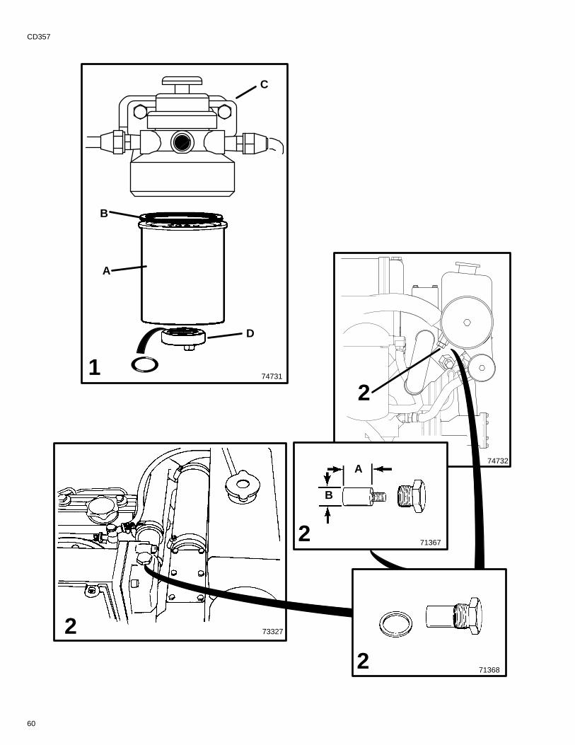
D
713682
1
2
2
74732
73327
74731
A
B
C
713672
A
B
60
CD357
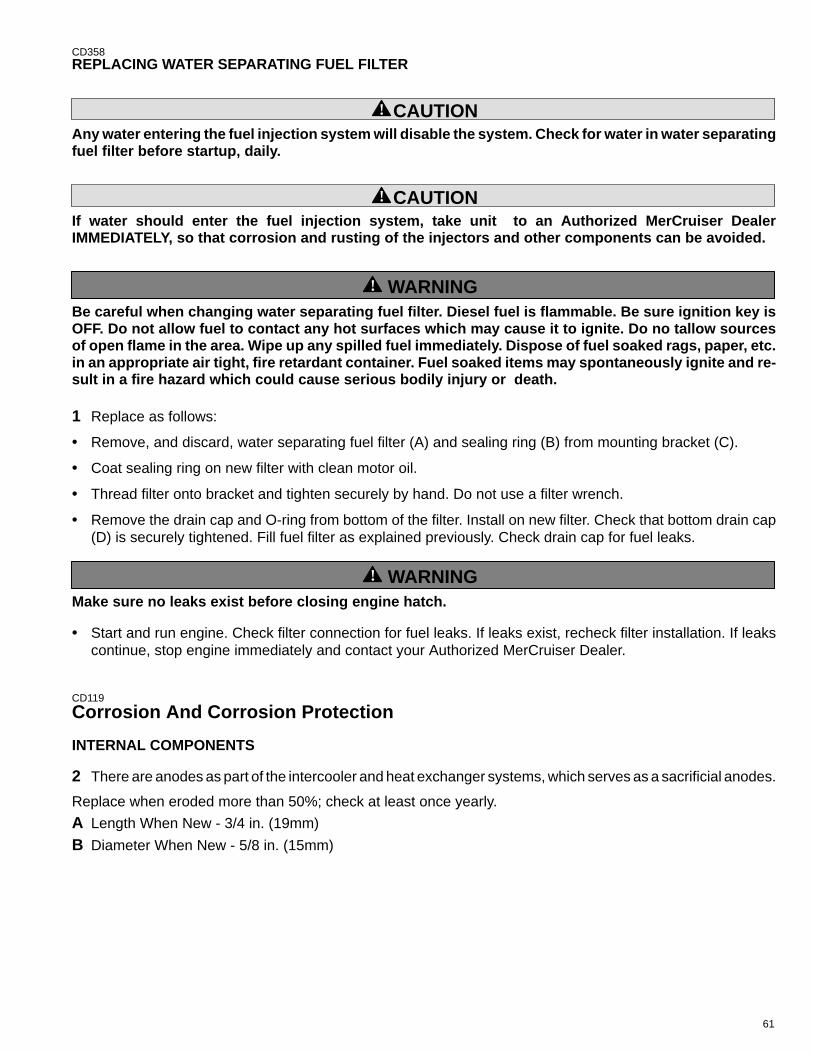
61
CD358REPLACING WATER SEPARATING FUEL FILTER
! CAUTIONAny water entering the fuel injection system will disable the system. Check for water in water separatingfuel filter before startup, daily.
! CAUTIONIf water should enter the fuel injection system, take unit to an Authorized MerCruiser DealerIMMEDIATELY, so that corrosion and rusting of the injectors and other components can be avoided.
! WARNINGBe careful when changing water separating fuel filter. Diesel fuel is flammable. Be sure ignition key isOFF. Do not allow fuel to contact any hot surfaces which may cause it to ignite. Do no tallow sourcesof open flame in the area. Wipe up any spilled fuel immediately. Dispose of fuel soaked rags, paper, etc.in an appropriate air tight, fire retardant container. Fuel soaked items may spontaneously ignite and re-sult in a fire hazard which could cause serious bodily injury or death.
1 Replace as follows:
• Remove, and discard, water separating fuel filter (A) and sealing ring (B) from mounting bracket (C).
• Coat sealing ring on new filter with clean motor oil.
• Thread filter onto bracket and tighten securely by hand. Do not use a filter wrench.
• Remove the drain cap and O-ring from bottom of the filter. Install on new filter. Check that bottom drain cap(D) is securely tightened. Fill fuel filter as explained previously. Check drain cap for fuel leaks.
! WARNINGMake sure no leaks exist before closing engine hatch.
• Start and run engine. Check filter connection for fuel leaks. If leaks exist, recheck filter installation. If leakscontinue, stop engine immediately and contact your Authorized MerCruiser Dealer.
CD119
Corrosion And Corrosion Protection
INTERNAL COMPONENTS
2 There are anodes as part of the intercooler and heat exchanger systems, which serves as a sacrificial anodes.
Replace when eroded more than 50%; check at least once yearly.
A Length When New - 3/4 in. (19mm)
B Diameter When New - 5/8 in. (15mm)
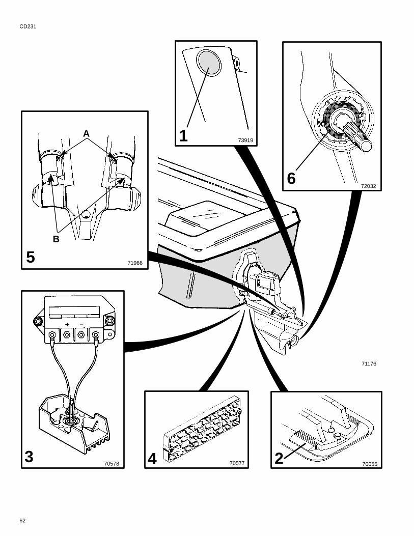
62
CD231
71176
705783
700552705774
5 71966
B
A 1 73919
720326
63
CD205
EXTERNAL COMPONENTS
Whenever two or more dissimilar metals (like those found on the stern drive) are submerged in a conductivesolution, such as saltwater, polluted water, or water with a high mineral content, a chemical reaction takes placecausing electrical current to flow between metals. The electrical current flow causes the metal that is most chemi-cally active, or anodic, to erode. This is known as galvanic corrosion and, if not controlled, it will in time causethe need for replacement of power package components exposed to water.
IMPORTANT: Replace sacrificial anodes if eroded 50% or more.
1 Universal Anodic Plate - serves as a sacrificial anode.
Remove plug from drive shaft housing to access attaching screw and insert 1/2 inch socket. Unthread attachingscrew and remove universal anodic plate. Do not remove screw. Install new anodic plate and tighten screwsecurely. Install plug.
2 Anodic Plate - serves as a sacrificial anode. Unscrew both attaching screws and remove. Install a new anodicplate and tighten securely.
3 MerCathode System - should be tested to ensure adequate output.
Test should be made where boat is moored, using Quicksilver Reference Electrode and Test Meter. Contact yourAuthorized MerCruiser Dealer to arrange for this test.
4 Anode Kit (if so equipped) - Mounted to boat transom. Acts as a sacrificial anode. Replace as required.
CA1635 Trim Cylinder Anodes - are mounted on each trim cylinder. To replace the trim cylinder anodes:
A Remove two screws from each anode.
B Install new anodes and tighten securely.
CD3596 Propeller Anode (Bravo One) - is located in front of the propeller, between the front side of the propeller andthe gear housing. Refer to “Propeller” section in this manual for propeller removal and installation. To replacethe propeller anode:
A Remove propeller.
B Remove two screws from anode.
C Install new anode and tighten securely.
D Reinstall propeller.

64
CD362
71176
1
2
3
4
6 5
65
CA168
In addition to the corrosion protection devices, the following steps should be taken to inhibit corrosion:
IMPORTANT: Corrosion damage that results from the improper application of anti-fouling paint will notbe covered by the limited warranty.
1 Painting Boat Hull or Boat Transom: Antifouling paint may be applied to boat hull and boat transom butyou must observe the following precautions:
IMPORTANT: DO NOT paint anodes or MerCathode System reference electrode and anode, as this willrender them ineffective as galvanic corrosion inhibitors.
IMPORTANT: If anti-fouling protection is required for boat hull or boat transom , copper or tin basepaints, if not prohibited by law, can be used. If using copper or tin based anti-fouling paints, observethe following:
2 Avoid any electrical interconnection between the MerCruiser Product, Anodic Blocks, or MerCathodeSystem and the paint by allowing a minimum of 1-1/2 in. (40mm) UNPAINTED area on transom of the boataround these items.
3 Painting Drive Unit or Transom Assembly: Drive unit and transom assembly should be painted with a goodquality marine paint or an anti-fouling paint that DOES NOT contain copper, tin, or any other material that couldconduct electrical current. Do not paint drain holes, anodes, MerCathode system, and items specified by boatmanufacturer.
4 Spray power package components on inside of boat every 2-3 weeks with Quicksilver Corrosion Guard toprotect finish from dulling and corrosion. External power package components may also be sprayed.
5 All lubrication points, especially steering system, shift and throttle linkages, should be kept well lubricated.
6 Flush cooling system periodically, preferably after each use.
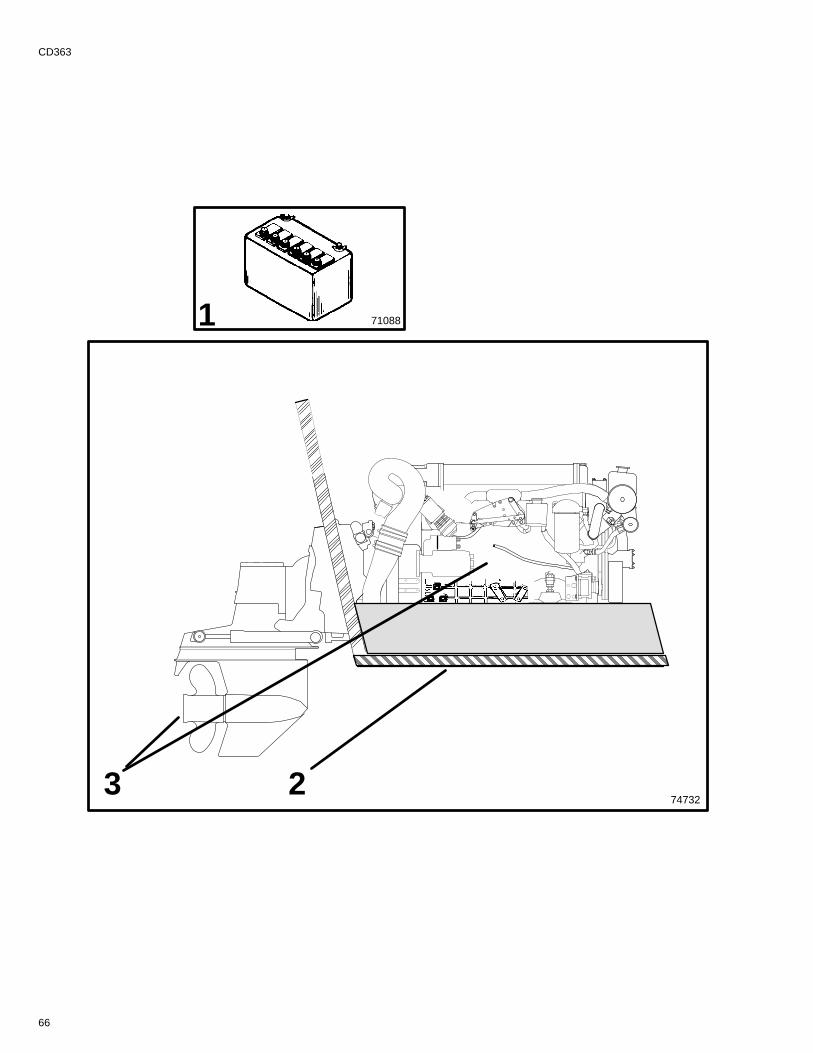
66
CD363
710881
374732
ÈÈÈÈÈÈÈÈÈÈÈÈÈÈÈÈ
2
67
CD15
Miscellaneous MaintenanceCA103
Battery1 All lead acid batteries discharge when not in use. Recharge every 30 to 45 days. or when specific gravity dropsbelow battery manufacturer’s specifications.
Refer to specific instructions and warnings accompanying your battery. If this information is not available, ob-serve the following precautions when handling a battery.
! WARNINGDo not use jumper cables and a booster battery to start engine. Do not recharge a weak battery in theboat. Remove battery and recharge in a ventilated area away from fuel vapors, sparks or flames.
! WARNINGBatteries contain acid which can cause severe burns - Avoid contact with skin, eyes and clothing Batter-ies also produce hydrogen and oxygen gasses when being charged. This explosive gas escapes fill/ventcell caps, and may form an explosive atmosphere around the battery for several hours after it has beencharged; sparks or flames can ignite the gas and cause an explosion which may shatter the battery andcould cause blindness or other serious injury.
Safety glasses and rubber gloves are recommended when handling batteries or filling with electrolyte.Hydrogen gases that escape from the battery during charging are explosive. When charging batteries,be sure area where batteries are located, is well-vented. Battery electrolyte is a corrosive acid andshould be handled with care. lf electrolyte is spilled or splashed on any part of the body, immediatelyflush the exposed area with liberal amounts of water and obtain medical aid as soon as possible.
CA104
Bottom Of Boat2 To maintain maximum speed, the following conditions of the boat bottom should be observed:
• Clean, free of barnacles and marine growth.
• Free of distortion, nearly flat where it contacts water.
• Straight and smooth fore and aft.
ANTIFOULING PAINTS
Refer to Antifouling Paint recommendations and related information on previous pages.
Refer to CORROSION AND CORROSION PROTECTION for additional information.
CE70
Inspection And Maintenance3 Inspect and/or maintain the following:
• Inspect power package often, and at regular intervals, to help maintain its top operating performance, andcorrect potential problems before they occur. The entire power package should be checked carefully includingall accessible engine parts.
• Check for loose, damaged or missing parts, hoses and clamps; tighten or replace as required.
• Remove and inspect propeller. If badly nicked, bent or cracked, see your dealer.
• Repair nicks and corrosion damage on power package exterior finish. Use Quicksilver spray paints - see yourAuthorized MerCruiser Dealer.
• Spray power package components on inside of boat every 2-3 weeks with Quicksilver Corrosion Guard toprotect finish from dulling and corrosion. External power package components may also be sprayed.
• All lubrication points (especially steering system, shift and throttle linkages) should be kept well lubricated.
• Flush seawater cooling circuit periodically (preferably after each use).
68
CA378
Cold Weather Or Extended StoragePower Package LayupIMPORTANT: MerCruiser strongly recommends that this service should be performed by an AuthorizedMerCruiser Dealer. Damage caused by freezing IS NOT covered by the MerCruiser Limited Warranty.CA115
Battery Winter StorageFollow battery manufacturer’s instructions for storage.
CD360
Power Package Recommissioning
! WARNINGTo prevent possible injury or damage to equipment, do not install battery until all maintenance has beenperformed on engine.
1 Check that all cooling system hoses are in good condition, connected properly, and hose clamps are tight.
2 Install seawater pump impeller, as follows:.
IMPORTANT: Use new gasket. Install in correct position - wide surface (D) on side of cam.
• Place impeller in pump and press onto pump shaft firmly.
• Install pump cover, with gasket, and tighten screws securely.
3 Replace fuel filter.
4 Bleed fuel system (see “MAINTENANCE - FUEL SYSTEM”).
! CAUTIONWhen installing battery, be sure to connect POSITIVE (+) battery cable to POSITIVE (+) battery terminalFIRST, and NEGATIVE (–) battery cable to NEGATIVE (–) battery terminal LAST. It battery cables are re-versed, or connection order is reversed, electrical system damage will result.
5 Install fully-charged battery. Clean battery cable clamps and terminals and reconnect cables (see CAUTIONlisted above). Secure each cable clamp when connecting. Coat terminals with a battery terminal anti-corrosionspray to help retard corrosion.
6 Perform all checks on OPERATION CHART in the STARTING PROCEDURE column.
IMPORTANT: On D3.6L/180 and D4.2L/220 Engines: After not having been operated for two months orlonger, it is necessary to pre-lubricate the engine. To do this, hold the “STOP” switch toggle lever DOWNwhile you simultaneously turn the key switch to “START” position for 15 seconds. This will rotate thestarter motor and engine/oil pump. During this process the engine will not run because no fuel is in-jected. Allow the starter motor to cool down for one minute and repeat the above described process. Toavoid overheating the starter motor, do not engage starter motor for more than 15 seconds each time.
7 Pre-lubricate the engine if necessary. Refer to above “Important” information. Start engine and closely ob-serve instrumentation to make sure that all systems are functioning correctly.
8 Carefully inspect engine for fuel, oil, fluid, water and exhaust leaks.
9 Check steering system, shift and throttle control for proper operation.
69
CD49
Troubleshooting
CD361
Starter Motor Will Not Crank Engine, Or Cranks It Very Slowly
Possible Cause Remedy• Battery switch turned off • Turn switch on.
• Remote control not in neutral position • Position control lever in neutral.
• Open circuit breaker or blown fuse • Check and reset circuit breaker or replace fuse.
• Loose or dirty electrical connections or dam-aged wiring
• Check all electrical connections and wires (especiallybattery cables). Clean and tighten faulty connection.
• Bad battery • Test and replace if bad.
Engine Will Not Start, Or Is Hard To Start
Possible Cause Remedy• Improper starting procedure • Read starting procedure.
• Empty fuel tank or fuel shutoff valve closed • Fill tank or open valve.
• Faulty mechanical fuel delivery pump • Have pump replaced by an Authorized Mer-Cruiser Dealer, if fuel is present.
• Throttle not operating properly • Check throttle for freedom of movement.
• Faulty electrical stop-circuit • Have Authorized MerCruiser Dealer serviceelectric stop-circuit.
• Clogged fuel filters • Replace filters.
• Stale or contaminated fuel • If contaminated, drain tank. Fill with fresh fuel.
• Fuel line or tank vent line kinked orclogged
• Replace kinked lines or blow out lines withcompressed air to remove obstruction.
• Air in fuel injection system • Purge fuel injection system.
• Glow-plugs or glow-plug system inoperative,if so equipped
• Test, and repair or replace components
• EDI System fault. • Have EDI System checked by an AuthorizedMerCruiser Dealer.
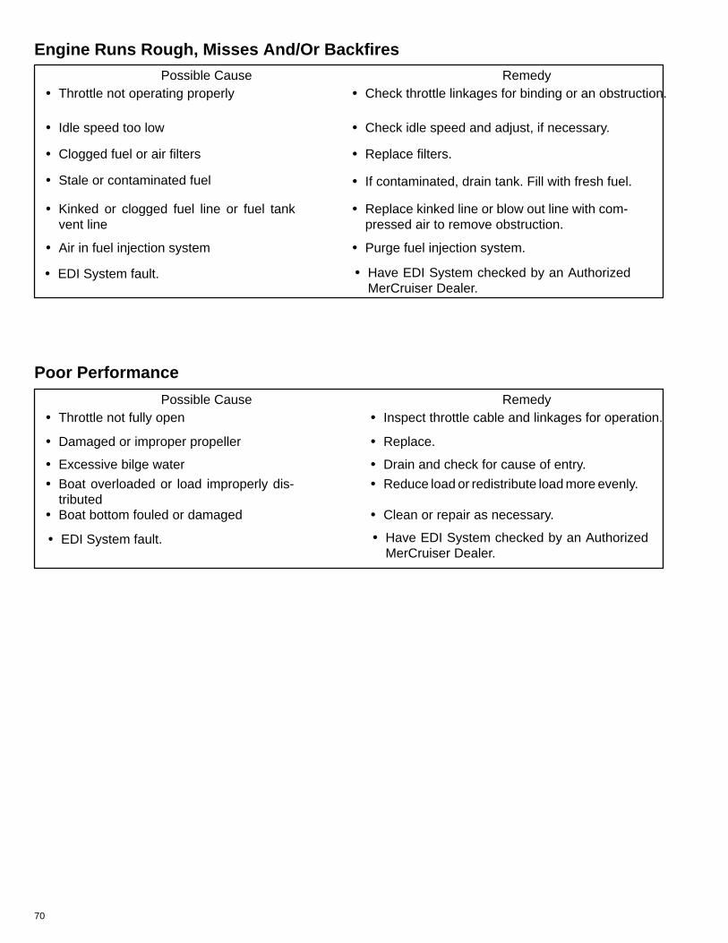
70
Engine Runs Rough, Misses And/Or BackfiresPossible Cause Remedy
• Throttle not operating properly • Check throttle linkages for binding or an obstruction.
• Idle speed too low • Check idle speed and adjust, if necessary.
• Clogged fuel or air filters • Replace filters.
• Stale or contaminated fuel • If contaminated, drain tank. Fill with fresh fuel.
• Kinked or clogged fuel line or fuel tankvent line
• Replace kinked line or blow out line with com-pressed air to remove obstruction.
• Air in fuel injection system • Purge fuel injection system.
• EDI System fault. • Have EDI System checked by an AuthorizedMerCruiser Dealer.
Poor Performance
Possible Cause Remedy• Throttle not fully open • Inspect throttle cable and linkages for operation.
• Damaged or improper propeller • Replace.
• Excessive bilge water • Drain and check for cause of entry.
• Boat overloaded or load improperly dis-tributed
• Reduce load or redistribute load more evenly.
• Boat bottom fouled or damaged • Clean or repair as necessary.
• EDI System fault. • Have EDI System checked by an AuthorizedMerCruiser Dealer.
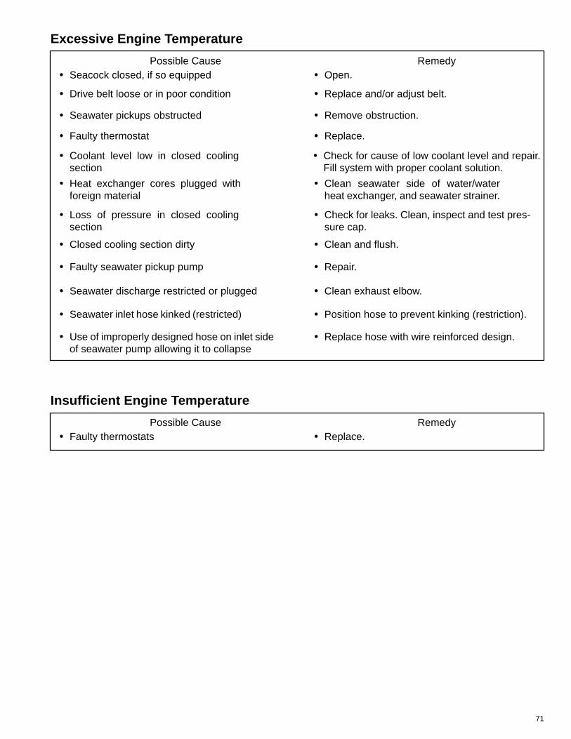
71
Excessive Engine Temperature
Possible Cause Remedy• Seacock closed, if so equipped • Open.
• Drive belt loose or in poor condition • Replace and/or adjust belt.
• Seawater pickups obstructed • Remove obstruction.
• Faulty thermostat • Replace.
• Coolant level low in closed coolingsection
• Check for cause of low coolant level and repair.Fill system with proper coolant solution.
• Heat exchanger cores plugged withforeign material
• Clean seawater side of water/waterheat exchanger, and seawater strainer.
• Loss of pressure in closed coolingsection
• Check for leaks. Clean, inspect and test pres-sure cap.
• Closed cooling section dirty • Clean and flush.
• Faulty seawater pickup pump • Repair.
• Seawater discharge restricted or plugged • Clean exhaust elbow.
• Seawater inlet hose kinked (restricted) • Position hose to prevent kinking (restriction).
• Use of improperly designed hose on inlet sideof seawater pump allowing it to collapse
• Replace hose with wire reinforced design.
Insufficient Engine Temperature
Possible Cause Remedy• Faulty thermostats • Replace.
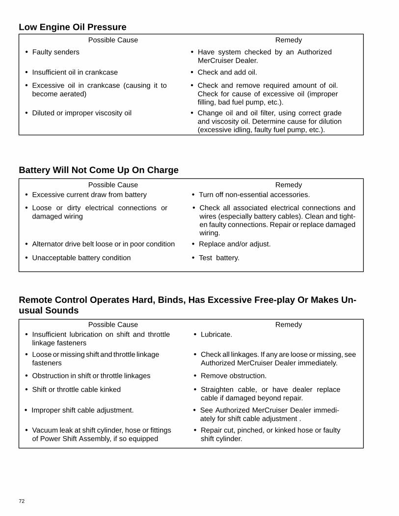
72
Low Engine Oil PressurePossible Cause Remedy
• Insufficient oil in crankcase • Check and add oil.
• Excessive oil in crankcase (causing it tobecome aerated)
• Check and remove required amount of oil.Check for cause of excessive oil (improperfilling, bad fuel pump, etc.).
• Diluted or improper viscosity oil • Change oil and oil filter, using correct gradeand viscosity oil. Determine cause for dilution(excessive idling, faulty fuel pump, etc.).
• Faulty senders • Have system checked by an AuthorizedMerCruiser Dealer.
Battery Will Not Come Up On Charge
Possible Cause Remedy• Excessive current draw from battery • Turn off non-essential accessories.
• Loose or dirty electrical connections ordamaged wiring
• Check all associated electrical connections andwires (especially battery cables). Clean and tight-en faulty connections. Repair or replace damagedwiring.
• Alternator drive belt loose or in poor condition • Replace and/or adjust.
• Unacceptable battery condition • Test battery.
Remote Control Operates Hard, Binds, Has Excessive Free-play Or Makes Un-usual Sounds
Possible Cause Remedy• Insufficient lubrication on shift and throttle
linkage fasteners• Lubricate.
• Loose or missing shift and throttle linkagefasteners
• Check all linkages. If any are loose or missing, seeAuthorized MerCruiser Dealer immediately.
• Obstruction in shift or throttle linkages • Remove obstruction.
• Shift or throttle cable kinked • Straighten cable, or have dealer replacecable if damaged beyond repair.
• Vacuum leak at shift cylinder, hose or fittingsof Power Shift Assembly, if so equipped
• Repair cut, pinched, or kinked hose or faultyshift cylinder.
• Improper shift cable adjustment. • See Authorized MerCruiser Dealer immedi-ately for shift cable adjustment .
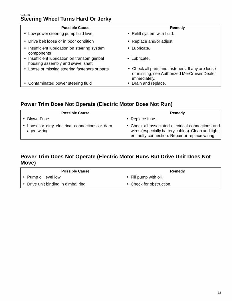
73
CD130
Steering Wheel Turns Hard Or Jerky
Possible Cause Remedy
• Low power steering pump fluid level • Refill system with fluid.
• Drive belt loose or in poor condition • Replace and/or adjust.
• Insufficient lubrication on steering system components
• Lubricate.
• Insufficient lubrication on transom gimbal housing assembly and swivel shaft
• Lubricate.
• Check all parts and fasteners. If any are looseor missing, see Authorized MerCruiser Dealerimmediately.
• Drain and replace.
• Loose or missing steering fasteners or parts
• Contaminated power steering fluid
Power Trim Does Not Operate (Electric Motor Does Not Run)
• Check all associated electrical connections andwires (especially battery cables). Clean and tight-en faulty connection. Repair or replace wiring.
Possible Cause Remedy
• Blown Fuse • Replace fuse.
• Loose or dirty electrical connections or dam-aged wiring
Power Trim Does Not Operate (Electric Motor Runs But Drive Unit Does NotMove)
• Check for obstruction.
Possible Cause Remedy
• Pump oil level low • Fill pump with oil.
• Drive unit binding in gimbal ring
74
CD54
Warranty Information
CD55
Owner Warranty Registration
UNITED STATES AND CANADA ONLY
• It is important that your selling dealer fills out the Warranty Registration Card completely and mails it to thefactory immediately upon sale of the new product.
• It identifies name and address of the original purchaser, product model and serial number(s), date of sale,type of use and selling dealer’s code, name and address. The dealer also certifies that you are the originalpurchaser and user of the product.
• Upon receipt of the Warranty Registration Card at the factory, you will be issued a plastic Owner WarrantyRegistration Card which is your only valid registration identification. It must be presented to the servicing deal-er should warranty service be required. Warranty claims will not be accepted without presentation of this card.
• A temporary Owner Warranty Registration Card will be presented to you when you purchase the product Itis valid only for 30 days from date of sale while your plastic Owner Warranty Registration Card is being pro-cessed Should your product need service during this period, present the temporary registration card to thedealer. He will attach it to your warranty claim form.
• Because of your selling dealer’s continuing personal interest in your satisfaction, the product should be re-turned to him for warranty service.
• If your plastic card is not received within 30 days from date of new product sale, please contact your sellingdealer.
• The product warranty is not effective until the product is registered at the factory.
• NOTICE: Registration lists must be maintained by factory and dealer on marine products sold in the UnitedStates, should notification under the federal boat safety act be required.
75
CD56
International Owner Registration
OUTSIDE THE UNITED STATES AND CANADA
• It is important that your selling dealer fills out the Warranty Registration Card completely and mails it to thedistributor or Marine Power Service Center responsible for administering the warranty registration/claim pro-gram for your area.
• The Warranty Registration Card identifies your name and address, product model and serial number(s), dateof sale, type of use and the selling distributors/dealer’s code number, name and address. The distributor/deal-er also certifies that you are the original purchaser and user of the product.
• A copy of the Warranty Registration Card, designated as the “Purchaser’s Copy”, MUST be given to you im-mediately after the card has been completely filled out by the selling distributor/dealer. This card representsyour factory registration identification, and should be retained by you for future use when required Should youever require warranty service on this product, your dealer may ask you for the Warranty Registration Cardto verify date of purchase and to use the information on the card to prepare the warranty claim form(s).
• In some countries, the Marine Power Service Center will issue you a permanent (plastic) Warranty Registra-tion Card within 30 days after receiving the “Factory Copy” of the Warranty Registration Card from your distrib-utor/dealer If you receive a plastic Warranty Registration Card, you may discard the “Purchaser’s Copy” thatyou received from the distributor/dealer when you purchased the product. Ask your distributor/dealer if thisplastic card program applies to you.
• For further information concerning the Warranty Registration Card and its relationship to Warranty Claim pro-cessing, refer to the “International Warranty.” Refer to “Table of Contents.”
IMPORTANT: Registration lists must be maintained by the factory and dealer in some countries by law.It is our desire to have ALL products registered at the factory should it ever be necessary to contact you.Make sure your dealer/distributor fills out the warranty registration card immediately and sends the fac-tory copy to the Marine Power International Service Center for your area.
76
CD212
Warranty Policy
Mercruiser Diesel Limited Warranty
I. We warrant each new production MerCruiser Diesel Stern Drive Power Package, Inboard Engine andAccessories attached thereto (hereafter referred to as “Product”), manufactured by MerCruiser (hereafterreferred to as the “Company”), and sold to the consumer in a country to which distribution is authorized bythe Company, to be free from defects in material and workmanship. This warranty shall apply only topleasure craft and light-duty craft applications.
II. This warranty shall become effective upon the date of sale to the first purchaser or user of the Product.The warranty period for Pleasure Craft applications is one (1) year from date of sale to the first purchaseror user of the product. The warranty period for Light-Duty Craft applications is one (1) year from date ofsale to the first purchaser or user of the product, or the accumulation of 500 hours of engine operation,whichever occurs first. The unused period of the applicable warranty, if any, is transferable to subsequentpurchasers. If the law applicable in the Country, State or Province where the product is sold prohibitslimitation of warranty coverage to one (1) year, then the warranty shall be the minimum period required bylaw. For purposes of this warranty Pleasure Craft is defined as a recreational planing craft used only andexclusively for pleasure and recreation. Light-Duty Craft is defined as a planing hull vessel used in any lawenforcement, commercial, or professional entertainment activity, or used in any enterprise or venture inwhich revenue in any amount is generated directly or indirectly.
III. To validate the warranty, the “Warranty Registration Card”, included with each Product, must be properlycompleted by the selling dealer and forwarded immediately after the sale to Mercury Marine (U.S.A. andCanada) or to a Marine Power International Branch, or Distributor Service Office (outside the U.S.A. andCanada).
IV. Purchaser must provide proof of purchase and substantiate the original date of sale by presenting to thedealer, authorized to service the Product, the original purchaser’s copy of the “Warranty Registration Card”or the “Owner Warranty Registration Card”. If either of these items is not available, purchaser must providea copy of the original purchaser’s “Bill of Sale” (Sales Contract) for the Product to be serviced. Warrantyclaims will not be accepted by the dealer until the original date of sale and Product serial number can beverified.
V. It is a condition for the continuation of this warranty that the Product be taken to an authorized MerCruiserService Dealer, after 20 hours of engine operation, but not later than 50 hours, for required checks andadjustments. A copy of the dealer service work order must be retained as evidence of the completion ofthis requirement.
VI. Since this warranty applies to defects in material or workmanship, it does not apply to normal wear,adjustments, tune-ups or to damage caused by: 1) Neglect, lack of maintenance, accident, abnormaloperation, improper installation or service; 2) Use of a propeller not properly suited to application/boat loador, failure to follow instructions in applicable service and warranty information manuals or operation andmaintenance manual; 3) Use of an accessory or part not manufactured or sold by us; 4) Operation withfuels, oils, lubricants or coolants/coolant additives which are not suitable for use with the Product orrecommended by us; 5) Participating in or preparing for racing or other competitive activity or operating withracing type lower unit; 6) Alteration or removal of parts; 7) Water entering engine cylinder/s through theexhaust system or air intake system; 8) Use of product in a full-displacement or semi-displacement hullvessel; or 9) Use or operation of the product in a manner inconsistent with the “RecommendedOperation/Duty Cycle” section of the Operation and Maintenance Manual.
77
CD213
Mercruiser Diesel Limited Warranty (continued)
VII. Reasonable access must be provided to the Product for warranty service. This warranty will not apply to:1) Haul-out, launch, towing and storage charges, telephone or rental charges of any type, inconvenience,or loss of time or income, or other consequential damages; or 2) Removal and/or replacement of boat parti-tions or material because of boat design for necessary access to the Product.
VIII. Claim shall be made under this warranty by delivering the Product for inspection to a MerCruiser dealerauthorized to service the Product. If purchaser cannot deliver Product to such authorized dealer, he maygive notice in writing to the Company (U.S.A. and Canada) or the nearest Marine Power InternationalBranch or Distributor Service Office (outside the U.S.A. and Canada). We shall then arrange for the inspec-tion and repair, provided such service is covered under this warranty. Purchaser shall pay for all relatedtransportation charges and/or travel time. If the service is not covered by this warranty, purchaser shallpay for all related labor and material, and any other expenses associated with that service. Any Productor parts shipped by purchaser for inspection or repair must be shipped with transportation charges prepaid.
IX. Our obligation under this warranty shall be limited to repairing a defective part or, at our option, refundingthe purchase price or replacing such part or parts as shall be necessary to remedy any malfunction resultingfrom defects in material or workmanship as covered by this warranty. The repair or replacement of parts,or the performance of service, under this warranty, does not extend the period of this warranty beyond itsoriginal expiration date. We reserve the right to improve the design of any Product without assuming anyobligation to modify any Product previously manufactured.
X. ALL INCIDENTAL AND/OR CONSEQUENTIAL DAMAGES ARE EXCLUDED FROM THIS WARRANTY.WARRANTIES OF MERCHANTABILITY AND FITNESS ARE EXCLUDED FROM THIS WARRANTY. IM-PLIED WARRANTIES ARE LIMITED TO THE LIFE OF THIS WARRANTY. SOME STATES OR COUN-TRIES DO NOT ALLOW LIMITATIONS ON HOW LONG AN IMPLIED WARRANTY LASTS OR THE EX-CLUSION OR LIMITATION OF INCIDENTAL OR CONSEQUENTIAL DAMAGES, SO THE ABOVELIMITATION OR EXCLUSIONS MAY NOT APPLY TO YOU.
XI. This warranty gives you specific legal rights and you may also have other legal rights which vary from stateto state and country to country.
78
CD278
Marine Power International Branch or Distributor Service Offices
INTERNATIONAL HEADQUARTERS AUSTRALIA
Marine Power InternationalDivision of Brunswick CorporationP.O. Box 1939Fond du Lac, Wl 54936-1939USATelephone: (414) 929-5000
Marine Power International Pty. Ltd.P. B. 1420, 132-140 Frankston RoadDandenong, Victoria 3164AustraliaTelephone (61) (3) 791-5822Fax (61) (3) 791-5880
EUROPE, MIDDLE EAST, AFRICA ASIA / PACIFIC
Marine Power Europe, Inc.Parc Industriel de Petit-RechainB-4800 VerviersBelgiumTelephone (0) 87 / 32 • 32 • 11Fax (32) (87) 31 • 19 • 65
Marine Power International, Ltd. Block 1002 Jalan Bukit Merah #07-08Redhill Industrial EstateJTC Flatted FactoriesSingapore 0315Telephone (65) 270-7680Fax (65) 270-7898
LATIN AMERICA, CARIBBEAN JAPAN
Marine Power International9350 SW 72nd St. (Sunset Dr.)Suite 100Miami, FL 33173U.S.A.Telephone (305) 596-9606Fax (305) 596-3869
Marine Power International - Japan No. 27-2 Muramatsu Chisaki-shindenShimizu CityShizuoka PrefectureJapan 424Telephone (81) 543/34-2500Fax (81) 543/34-2022
79
CD279
Warranty CoverageThe purpose of this section is to help eliminate some of the more common misunderstandings regarding warran-ty coverage. The table explains some of the types of services that are not covered by warranty.Keep in mind that warranty covers repairs that are needed within the warranty period because of defects in mate-rial and workmanship. Installation errors, accidents normal wear and a variety of other causes that affect theproduct are not covered.Warranty is limited to defects in material or workmanship, but only when the consumer sale is made in the countryto which distribution is authorized by us.Should you have any questions concerning warranty coverage contact your authorized dealer. They will bepleased to answer any questions that you may have.
WARRANTY DOES NOT APPLY TO THE FOLLOWING:
• Minor adjustments or checks, including checking fuel injection pump timing, cleaning fuel injectors, filters, oradjusting belts, controls, and checking lubrication made in connection with normal services.
• Damage caused by neglect, lack of maintenance, accident, abnormal operation, improper installation or ser-vice, or freezing temperatures.
• Haul-out, launch, towing charges; removal and/or replacement of boat partitions or material because of boatdesign for necessary access to the product; all related transportation charges and/or travel time, etc. Reason-able access must be provided to the product for warranty service. Customer must deliver product to an Autho-rized Dealer.
• Additional service work requested by customer other than that necessary to satisfy the warranty obligation.
• Labor performed by other than an Authorized Dealer may be covered only under following circumstances:When performed on emergency basis (providing there are no Authorized Dealers in area who can performthe work required or have no facilities to haul out, etc., and prior factory approval has been given to have thework performed at this facility).
• All incidental and/or consequential damages (storage charges, telephone or rental charges of any type, in-convenience or loss of time or income) are the owner’s responsibility.
• Use of other than Quicksilver replacement parts when making warranty repairs.
• Oils, lubricants or fluids changed as a matter of normal maintenance is customer’s responsibility unless lossor contamination of same is caused by product failure that would be eligible for warranty consideration.
• Participating in or preparing for racing or other competitive activity.
• Engine noise does not necessarily indicate a serious engine problem. If diagnosis indicates a serious internalengine condition which could result in a failure, condition responsible for noise should be corrected under thewarranty.
• Lower unit and/or propeller damage caused by striking a submerged object is considered a marine hazard.
• Water entering the engine via the air filter or exhaust system or submersion. Also, water in the starter motor.
• Starter motors and/or armatures or field coil assembly, which are burned, or where lead is thrown out of com-mutator because of excess cranking.
• Valve or valve seat grinding required because wear.
• Failure of any parts caused by lack of cooling water, which results from starting power package out of water,foreign material blocking inlets or power package being mounted too high.
• Use of fuels and lubricants which are not suitable for use with or on the product. Refer to your Operation andMaintenance Manual.
• Our limited warranty does not apply to any damage to our products caused by the installation or use of partsand accessories which are not manufactured or sold by us. Failures which are not related to the use of thoseparts or accessories, are covered under warranty, if they otherwise meet the terms of the limited warranty forthat product.
80
CD62
Transferable Warranty
The product warranty is transferable to a subsequent purchaser, but only for the remainder of the unused portionof the limited warranty. This will not apply to products used for commercial applications.
DIRECT SALE BY OWNER
• The second owner can be registered as the new owner and retain the unused portion of the limited warrantyby sending the former owner’s plastic Owner Warranty Registration Card and a copy of the bill of sale to showproof of ownership. In the United States and Canada, mail to:
Mercury MarineW6250 West Pioneer RoadP.O. Box 1939Fond du Lac, Wl 54936-1939Attn: Warranty Registration Department
• A new Owner Warranty Registration Card will be issued with the new owner’s name and address. Registrationrecords will be changed on the factory computer registration file.
• There is no charge for this service.
Outside the United States and Canada, please contact the distributor in your country, or the Marine Pow-er International Service Center closest to you, for the transferable warranty procedure that would applyto you.
Q-GUARD Product Protection Plan
UNITED STATES AND CANADA ONLY
(Certain Performance Products, triple engine installations, and commercial applications are excluded)
The Mercury Marine Q-GUARD Product Protection Plan provides coverage against unexpected mechanical andelectrical breakdowns that may occur beyond the standard limited warranty.
The optional Q-GUARD Product Protection Plan is the only Factory Plan available for your engine.
Two, three or four-year plans can be purchased up to 180 days after the original engine purchase date.
See your participating dealer for complete program details.
EXTRA HELP
81
CA461
Owner Service AssistanceLocal Repair ServiceAlways return your MerCruiser powered boat to your local Authorized Dealer, should the need for service arise.Only he has the factory trained mechanics, knowledge, special tools and equipment and the genuine Quicksilverparts and accessories* to properly service your engine should the need occur. He knows your engine best.
* Quicksilver parts and accessories are engineered and built by Mercury Marine, specifically for MerCruiserstern drives and inboards.
Service Away From HomeIf you are away from your local dealer and the need arises for service, contact the nearest Authorized Dealer.Refer to the Yellow Pages of the telephone directory. If, for any reason, you cannot obtain service, contact thenearest Regional Service Center. Outside the United States and Canada, contact the nearest Marine PowerInternational Service Center.
Parts And Accessories InquiriesAll inquiries concerning Quicksilver replacement parts and accessories should be directed to your localAuthorized Dealer. The dealer has the necessary information to order parts and accessories for you should henot have them in stock. Only Authorized Dealers can purchase genuine Quicksilver parts and accessories fromthe factory. Mercury Marine does not sell to unauthorized dealers or retail customers. When inquiring on partsand accessories, the dealer requires the motor model and serial number(s) to order the correct parts.
CB577
Resolving A ProblemSatisfaction with your MerCruiser product is very important to your dealer and to us. If you ever have a problem,question or concern about your power package, contact your dealer or any Authorized MerCruiser Dealership.If additional assistance is required, take these steps.
1 Talk with the dealership’s sales manager or service manager. If this has already beendone, then contact the owner of the dealership.
2 Should you have a question, concern or problem that cannot be resolved by your deal-ership, please contact Mercury Marine Service Office for assistance. Mercury Marine willwork with you and your dealership to resolve all problems.
The following information will be neededby the service office:
• Your name and address
• Daytime telephone number
• Model and serial number for your power package
• The name and address of your dealership
• Nature of problem
Mercury Marine Service Offices are listed on the next page.
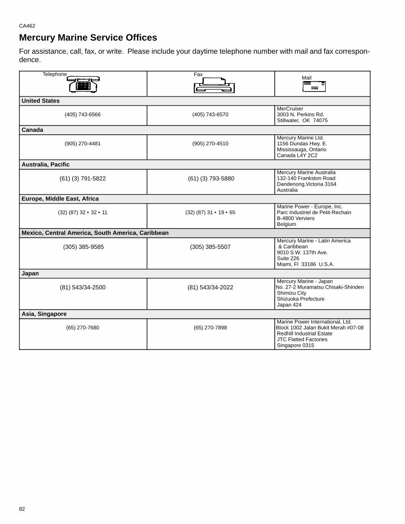
82
CA462
Mercury Marine Service OfficesFor assistance, call, fax, or write. Please include your daytime telephone number with mail and fax correspon-dence.
Telephone FaxMail
United States
(405) 743-6566 (405) 743-6570MerCruiser3003 N. Perkins Rd.Stillwater, OK 74075
Canada
(905) 270-4481 (905) 270-4510Mercury Marine Ltd.1156 Dundas Hwy. E.Mississauga, OntarioCanada L4Y 2C2
Australia, Pacific
(61) (3) 791-5822 (61) (3) 793-5880Mercury Marine Australia132-140 Frankston RoadDandenong,Victoria 3164Australia
Europe, Middle East, Africa
(32) (87) 32 • 32 • 11 (32) (87) 31 • 19 • 65Marine Power - Europe, Inc.Parc Industriel de Petit-RechainB-4800 VerviersBelgium
Mexico, Central America, South America, Caribbean
(305) 385-9585 (305) 385-5507Mercury Marine - Latin America & Caribbean9010 S.W. 137th Ave.Suite 226Miami, Fl 33186 U.S.A.
Japan
(81) 543/34-2500 (81) 543/34-2022Mercury Marine - JapanNo. 27-2 Muramatsu Chisaki-ShindenShimizu CityShizuoka PrefectureJapan 424
Asia, Singapore
(65) 270-7680 (65) 270-7898Marine Power International, Ltd.Block 1002 Jalan Bukit Merah #07-08Redhill Industrial EstateJTC Flatted FactoriesSingapore 0315
83
CA463
Customer Service Literature
English LanguageEnglish language publications are available from:
Mercury MarineAttn: Publications Department
W6250 West Pioneer RoadP.O. Box 1939
Fond du Lac, WI 54936-1939
Outside the United States and Canada, contact the nearest Mercury Marine or Marine PowerInternational Service Center for further information.
When ordering be sure to:
1. List your product, model, year and serial number(s).
2. Check the literature and quantities you want.
3. Enclose full remittance in check or money order (NO C.O.D.’s).
CA464
Other LanguagesTo obtain an Operation and Maintenance Manual or Maintenance Procedures Manual in another language,contact the nearest Mercury Marine or Marine Power International Service Center for information. A list of partnumbers for other languages is provided with your power package.
caa464
Andre sprogKontakt det nærmeste Mercury Marine eller Marine Power International service center for oplysninger om hvor-dan du kan anskaffe en Betjenings– og vedligeholdelsesmanual eller en manual med vedligeholdelsesprocedur-er på et andet sprog. En liste med reservedelsnumre for andre sprog leveres sammen med din power–pakke.cab464
Andere talenVoor het verkrijgen van een Handleiding voor gebruik en onderhoud of een Onderhoudshandleiding in anderetalen dient u contact op te nemen met het dichtstbijzijnde internationale servicecentrum van Mercury Marine ofMarine Power voor informatie hierover. Een lijst met onderdeelnummers voor andere talen wordt bij uw motorins-tallatie geleverd.cac464
Muut kieletSaadaksesi Käyttö– ja huolto–ohjekirjoja muilla kielillä, ota yhteys lähimpään Mercury Marine tai Marine PowerInternational huoltokeskukseen, josta saat lähempiä tietoja. Moottorisi mukana seuraa monikielinen varaosa-numeroluettelo.cad464
Autres languesPour obtenir un Manuel d’utilisation et d’entretien ou un Manuel d’entretien dans une autre langue, contactezle centre de service après–vente international Mercury Marine ou Marine Power le plus proche pour toute in-formation. Une liste des numéros de pièces en d’autres langues accompagne votre bloc–moteur.
84
cae464
Andere SprachenUm eine Betriebs– und Wartungsanleitung oder ein Handbuch der Wartungsverfahren in einer anderen Sprachezu erhalten, wenden Sie sich an das nächste Mercury Marine oder Marine Power International Service Center.Eine Liste mit Teilenummern für Fremdsprachen ist im Lieferumfang Ihres Motors enthalten.caf464
Altre linguePer ottenere il manuale di funzionamento e manutenzione o il manuale delle procedure di manutenzione in altralingua, contattate il centro assistenza internazionale Mercury Marine o Marine Power più vicino. In dotazionecon il gruppo motore, viene fornito l’elenco dei codici prodotto dei componenti venduti all’estero.
Andre språkYtterligere informasjon om bruks– og vedlikeholdshåndbok eller servicehåndbok på andre språk kan fås vedhenvendelse til nærmeste internasjonale servicecenter for Mercury Marine eller Marine Power. En liste overdelenumre for andre språk følger med aggregatet.cah464
Outros IdiomasPara obter um Manual de Operação e Manutenção ou um Manual de Procedimentos de Manutenção em outroidioma, contate o Centro de Serviço Internacional de ”Marine Power” (Potência Marinha) ou a Mercury Marinemais próxima para obter informações. Uma lista de números de referência para outros idiomas é fornecida como seu pacote de propulsão.caj464
Otros idiomasPara obtener un Manual de operación y mantenimiento o un Manual de procedimientos en otro idioma, póngaseen contacto con el centro de servicio más cercano de Mercury Marine o Marine Power International para recibirinformación. Con su conjunto motriz se entrega una lista de los números de pieza para los otros idiomas.cak464
Andra språkFör att få Instruktions– och underhållsböcker på andra språk, kontakta närmaste Mercury Marine eller MarinePower International servicecenter, som kan ge ytterligare information. En förteckning över artikelnummer på an-dra språk medföljer ditt kraftpaket.
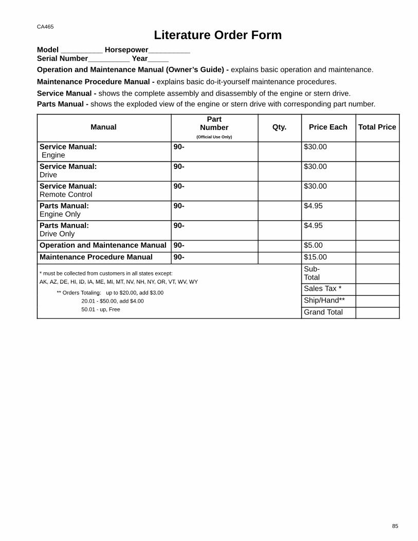
85
CA465
Literature Order FormModel __________ Horsepower__________Serial Number__________ Year_____Operation and Maintenance Manual (Owner’s Guide) - explains basic operation and maintenance.
Maintenance Procedure Manual - explains basic do-it-yourself maintenance procedures.
Service Manual - shows the complete assembly and disassembly of the engine or stern drive.Parts Manual - shows the exploded view of the engine or stern drive with corresponding part number.
ManualPart
Number(Official Use Only)
Qty. Price Each Total Price
Service Manual: Engine
90- $30.00
Service Manual: Drive
90- $30.00
Service Manual: Remote Control
90- $30.00
Parts Manual: Engine Only
90- $4.95
Parts Manual: Drive Only
90- $4.95
Operation and Maintenance Manual 90- $5.00
Maintenance Procedure Manual 90- $15.00
* must be collected from customers in all states except:
AK, AZ, DE, HI, ID, IA, ME, MI, MT, NV, NH, NY, OR, VT, WV, WY
Sub-Total
AK, AZ, DE, HI, ID, IA, ME, MI, MT, NV, NH, NY, OR, VT, WV, WY
** Orders Totaling: up to $20.00, add $3.00Sales Tax *
Orders Totaling: up to $20.00, add $3.00
20.01 - $50.00, add $4.00
50 01 F
Ship/Hand**50.01 - up, Free Grand Total
Card Number
Month/Year
Expiration Date
Signature
Telephone Number
Date
( )
Please Return with Payment to:
Mercury MarineAttn: Publications Dept.P.O. Box 1939Fond du Lac, WI 54936-1939
Ship To: (Please Print or Type - This is your Shipping Label)
Name
Address
City State Zip
86
METHOD OF PAYMENT: (NO CASH OR C.O.D.)
Personal Check Cashiers Check Money Order
Visa Master Card
75308
87
88
CALIFORNIA
PROPOSITION 65 WARNING
Diesel engine exhaust and some of its constituents are known
to the State of California to cause cancer, birth defects, and
other reproductive harm.