Diebold Nixdorf K2 Installation Manual
67
K-two Installation Guide (July 2018)
Transcript of Diebold Nixdorf K2 Installation Manual

K-two Installation Guide (July 2018)

We would like to know your opinion on this publication. Please send us a copy of this page if you have any constructive criticism on: - the contents - the layout - the product. We would like to thank you in advance for your comments. With kind regards, Diebold Nixdorf Wohlrabedamm 31 D-13629 Berlin e-mail: [email protected] _________________________________________________________________________________ Your opinion
Kiosk K-two - Site Preparation and Installation Guide Order No.: 01750299889B

All product names mentioned in this document are registered trademarks.
Copyright © Diebold Nixdorf, 2018 All rights including the rights to the translation, reprinting and transmission or copying by any
means, in whole or in part, are reserved. Offenders will be liable for damages. All rights including rights resulting from a patent grant or
registration of a utility or design are reserved.

Contents 1 Symbols ............................................................................................................................................ 1
2 Warranty .......................................................................................................................................... 1
3 Important Notes ............................................................................................................................... 2
3.1 Connecting Peripherals ..................................................................................................... 3
4 Overview .......................................................................................................................................... 4
4.1 Exterior view ..................................................................................................................... 4
4.2 Interior view ..................................................................................................................... 5
5 Opening the Kiosk ............................................................................................................................ 6
5.1 Opening ............................................................................................................................ 6
6 Dimensions ....................................................................................................................................... 7
6.1 Base Plate ......................................................................................................................... 7
6.2 Double-Sided Kiosk ........................................................................................................... 8
6.2.1 Service Area ...................................................................................................................... 8
6.3 Single-Sided Kiosk ............................................................................................................. 9
6.3.1 Service Area ...................................................................................................................... 9
6.4 Side View Single and Double Sided................................................................................. 10
6.5 K-two with 22”-display ................................................................................................... 11
6.5.1 On low and high pedestal ............................................................................................... 11
6.6 K-two with 27”-display ................................................................................................... 12
6.6.1 On low and high pedestal ............................................................................................... 12
7 Assembling Instructions: Pole-Mounted Kiosk .............................................................................. 13
7.1 Kiosk with Floor Cabling.................................................................................................. 13
7.2 Kiosk with Over-Floor Cabling ........................................................................................ 18
7.3 Kiosk with Ceiling Cabling ............................................................................................... 22
7.4 Attach Cable Duct ........................................................................................................... 23
8 EFT (Electronic-Funds-Transfer)-Terminal ..................................................................................... 26
9 MX915 ............................................................................................................................................ 29
10 Ingenico IUP/IUR 250/IUC 150 ....................................................................................................... 31
10.1 Installation ...................................................................................................................... 32
11 Verifone UX 100/200/300 .............................................................................................................. 35
11.1 Installation ...................................................................................................................... 36
12 CCV C60 .......................................................................................................................................... 39
12.1 Installation ...................................................................................................................... 40
13 Start up the System ........................................................................................................................ 43

14 Disconnecting the System from the Mains .................................................................................... 44
15 Permanent connection (North America) ....................................................................................... 45
15.1 Wiring from above .......................................................................................................... 45
15.2 Wiring from below .......................................................................................................... 48
16 Block diagram ................................................................................................................................. 51
17 Technical data ................................................................................................................................ 52
17.1 System ............................................................................................................................ 52
17.2 Environmental requirements ......................................................................................... 52
17.3 Electrical characteritics of the power supply ................................................................. 53
17.4 Device conditions............................................................................................................ 53
17.5 Noise emission in acc. withEN 27779 ............................................................................. 53
17.6 ACO Kiosk PC ................................................................................................................... 53
17.7 LCD 27” display ............................................................................................................... 54
17.8 LCD 22” Touch Display .................................................................................................... 55
17.9 TH230+ ............................................................................................................................ 56
18 Certifications of the Manufacturer ................................................................................................ 58
18.1 CE Marking ...................................................................................................................... 58
19 Recycling the Kiosk ......................................................................................................................... 59


1
The safety instructions given in this document should be strictly followed when handling the device. In case of doubts or questions please contact Diebold Nixdorf:
1 Symbols
i
This symbol is used to mark important information in this manual.
Text following this symbol should be given special attention in order to avoid damage and injury.
2 Warranty
Generally Diebold Nixdorf guarantees a warranty engagement for 12 months beginning with the date of delivery. This warranty engagement covers all damages which occur despite a normal use of the product.
Damages because of
• improper or insufficient maintenance,
• improper use of the product or unauthorized modifications of the product,
• inadequate location or surroundings
will not be covered by the warranty.
For further information on the stipulation consult your contract.
All parts of the product which are subject to wear and tear are not included in the warranty engage-ment. For detailed warranty arrangements please consult your contract documents.
Please contact your local service provider for all questions concerning your service contract.

2
3 Important Notes
Terminals supplied by Diebold Nixdorf comply with the respective safety regulations for data-processing installations and information technology installations, including electrical office equip-ment for use within an office environment.
Whenever work of any kind is done on the device, as well as when data cables are plugged and unplugged, the device must be completely disconnected from the line voltage.
• Terminals may only be installed and repaired by authorized technicians.
• Unauthorized opening of the housing or inexpert repairs can result not only in considerable per-sonal danger, but will also invalidate your warranty and liability protection.
• Always consult the enclosed documentation before doing any work with this terminal.
• If this terminal is brought from a cold environment into a heated place of business, condensation may occur. Before operation, the terminal must be completely dry. Therefore, an acclimatization period of at least two hours must be adhered too.
• Always lay the supply leads and cables in such a way that they cannot be stepped on or tripped over.
• Exchange damaged cables immediately.
• In order to completely disconnect the terminal from the power source use the separator in the fuse box\building installation.
• Make sure that no objects (such as paper clips) can reach the interior of the terminal, since elec-trical shocks or short-circuits could result.
• Ensure that the K-two receives adequate ventilation to avoid overheating.
• During an electrical storm, data cables should not be plugged in or being unplugged.
• Keep the terminal away from vibrations, dust, humidity and heat.
• Ensure that used parts are disposed of in an environmentally friendly manner.
• In case of an accident (such as a damaged housing, entry of liquids or foreign objects), switch the terminal off and use the separator to completely remove the terminal from power.
• The terminal and other information technology hardware should only be connected to electrical supply networks with a separate protective earth wire (PE). This type of electrical supply network is referred to as a TN-S network. Do not use PEN conductors. Also follow the recommendations set forth in DIN VDE 0100 Part 540, Appendix C2 as well as EN50174-2, §5.4.3 (www.DIN.de). This will help prevent malfunctions.

3
• National Electrical Code ANSI/NFPA 70-2005
• Canadian Electrical Code, Part I, CSA C22.1-02
• Always keep the ventilation slots free of obstruction to ensure adequate air circulation and avoid overheating.
• Transport the terminal only in its original packaging (to protect it against knocks and bumps).
• If a lithium battery is supplied with the terminal, ensure that the battery is replaced with an equivalent type. Otherwise there is danger of explosion! Lithium batteries may only be replaced with identical types or other types recommended by the manufacturer.
• Batteries must be disposed of according to local regulations on the disposal of special waste.
3.1 Connecting Peripherals
Use only shielded cables when connecting terminals to the system to ensure compliance with inter-national Rules and Regulations for radiated emission as well as to achieve a high immunity against external disturbances.

4
4 Overview
4.1 Exterior view
1 Pole Light 5 Lock
2 Display 6 Scanner
3 Printer 7 EFT*
4 ADA Navigation
* It may be connected ETFs with 12V for max. current consumption of 1.1A (permanent).
1
3
2
4
5
6
7

5
4.2 Interior view
1 Pole Light 6 ADA Navigation 11 Power Distributor
2 Display 7 NFC Module 12 Power Supply
3 Lock 8 Scanner 13 PC
4 EFT* 9 Printer
5 Speaker 10 Fan
* It may be connected ETFs with 12V for max. current consumption of 1.1A (permanent).
1
3
2
4
5
10
6 7 8 9
11
13
12
6
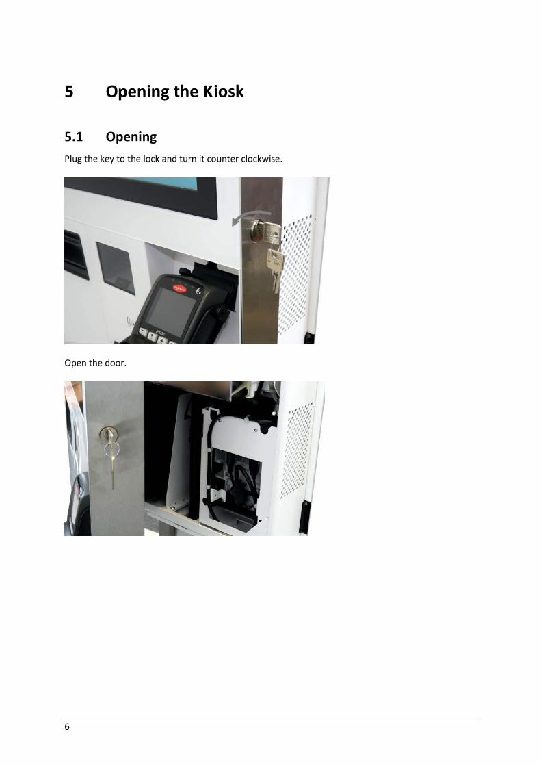
5 Opening the Kiosk
5.1 Opening Plug the key to the lock and turn it counter clockwise.
Open the door.

7
6 Dimensions
6.1 Base Plate

8
6.2 Double-Sided Kiosk
6.2.1 Service Area

9
6.3 Single-Sided Kiosk
6.3.1 Service Area

10
6.4 Side View Single and Double Sided

11
6.5 K-two with 22”-display
6.5.1 On low and high pedestal
K2 shown with standard kit for ceiling cabling, it can be enlarged up to two times with 1.151mm expansion kits.

12
6.6 K-two with 27”-display
6.6.1 On low and high pedestal
K2 shown with standard kit for ceiling cabling, it can be enlarged up to two times with 1.151mm ex-pansion kits.

13
7 Assembling Instructions: Pole-Mounted Kiosk
7.1 Kiosk with Floor Cabling The installation including the floor mounting has to be carried out by a trained technician after the assessment and evaluation of the constructional conditions on site. Assembling the Pole
The assembly pack for the pole includes: 1x silicon glue 2x stainless steel profile 1x base plate 8x M8x16 counter-sunk screws 1x adapter plate 1x stainless steel cover plate 6x counter-sunk screws with dowels 8x M6x10 counter-sunk screws 1x front cable cover 1x back cable cover
14
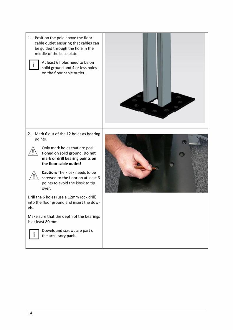
1. Position the pole above the floor cable outlet ensuring that cables can be guided through the hole in the middle of the base plate.
At least 6 holes need to be on solid ground and 4 or less holes on the floor cable outlet.
2. Mark 6 out of the 12 holes as bearing points.
Only mark holes that are posi-tioned on solid ground. Do not mark or drill bearing points on the floor cable outlet!
Caution: The kiosk needs to be screwed to the floor on at least 6 points to avoid the kiosk to tip over.
Drill the 6 holes (use a 12mm rock drill) into the floor ground and insert the dow-els.
Make sure that the depth of the bearings is at least 80 mm.
Dowels and screws are part of the accessory pack.

15
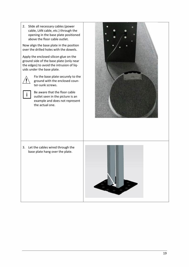
3. Slide all necessary cables (power cable, LAN cable, etc.) through the opening in the base plate positioned above the floor cable outlet.
Now align the base plate in the position over the drilled holes with the dowels.
Apply the enclosed silicon glue on the ground side of the base plate (only near the edges) to avoid the intrusion of liq-uids under the base plate.
Fix the base plate securely to the ground with the enclosed coun-ter-sunk screws.
Be aware that the floor cable outlet seen in the picture is an example and does not represent the actual one.
4. Let the cables wired through the
base plate hang over the plate.

16
5. Apply the enclosed silicon glue on the top side of the base plate. Take the stainless steel cover plate and move it over the profiles in direction to the base plate. It covers the screw heads.
Do not remove the foil yet!
Slots being at backside of the Kiosk
6. Set the kiosk chassis on the pole and fix it with eight M6x10 countersunk screws.
Please take care to avoid damages on the doors.
Caution: Two persons needed to pick up the kiosk and set it onto the pole.
7. Move the cables into the housing.

17
8. Set the front cover into place.
9. Fix it with two M4x6 screws to the
adapter
10. Set the back cover into place.
11. Fix it with one M4x6 screw to the
adapter.

18
7.2 Kiosk with Over-Floor Cabling The installation including the floor mounting has to be carried out by a trained technician after the assessment and evaluation of the constructional conditions on site. Assembling the Pole The assembly pack for the pole includes: 1 pole, pre-assembled 1x silicon glue 1x front cable cover 4xM6x10 pan head screw 1x back cable cover 2xM4x6 cheese head screws 8xM6x16 countersunk screws
1. Mark 6 out of the 12 holes as bearing points.
Only mark holes that are posi-tioned on solid ground. Do not mark or drill bearing points on the floor cable outlet!
Caution: The kiosk needs to be screwed to the floor on at least 6 points to avoid the kiosk to tip over.
Drill the 6 holes (use a 12mm rock drill) into the floor ground and insert the dow-els.
Make sure that the depth of the bearings is at least 80 mm.
Dowels and screws are part of the accessory pack.
19
2. Slide all necessary cables (power cable, LAN cable, etc.) through the opening in the base plate positioned above the floor cable outlet.
Now align the base plate in the position over the drilled holes with the dowels.
Apply the enclosed silicon glue on the ground side of the base plate (only near the edges) to avoid the intrusion of liq-uids under the base plate.
Fix the base plate securely to the ground with the enclosed coun-ter-sunk screws.
Be aware that the floor cable outlet seen in the picture is an example and does not represent the actual one.
3. Let the cables wired through the
base plate hang over the plate.

20
4. Apply the enclosed silicon glue on the top side of the base plate. Take the stainless steel cover plate and move it over the profiles in direction to the base plate. It covers the screw heads.
Do not remove the foil yet!
Slots being at backside of the Kiosk
5. Set the kiosk chassis on the pole and fix it with eight M6x10 countersunk screws.
Please take care to avoid damages on the doors.
Caution: Two persons needed to pick up the kiosk and set it onto the pole.
6. Move the cables into the housing.

21
7. Set the front cover into place.
8. Fix it with two M4x6 screws to the
adapter
9. Set the back cover into place.
10. Fix it with one M4x6 screw to the
adapter.

22
7.3 Kiosk with Ceiling Cabling The installation including the floor mounting has to be carried out by a trained technician after the assessment and evaluation of the constructional conditions on site. Before beginning with the installation of the kiosk, a ceiling area needs to be choosen where
- no lamps - no electric cables - no ledger
are located where the ceiling channel will enter the ceiling. There are two possibilities on how to find this area:
1. Place the base plate with the attached stainless steel profiles on a chosen spot. Attach a laser pointer pointing upwards to determine where the ceiling channel will enter the ceiling. OR
2. Choose a spot on the ceiling and drop a perpendicular with the help of a string to determine where the base plate should be positioned.
Assembling the Pole Follow step 1-6 and 8-12 of chapter 7.2 for single-sided kiosk and chapter 7.4
23
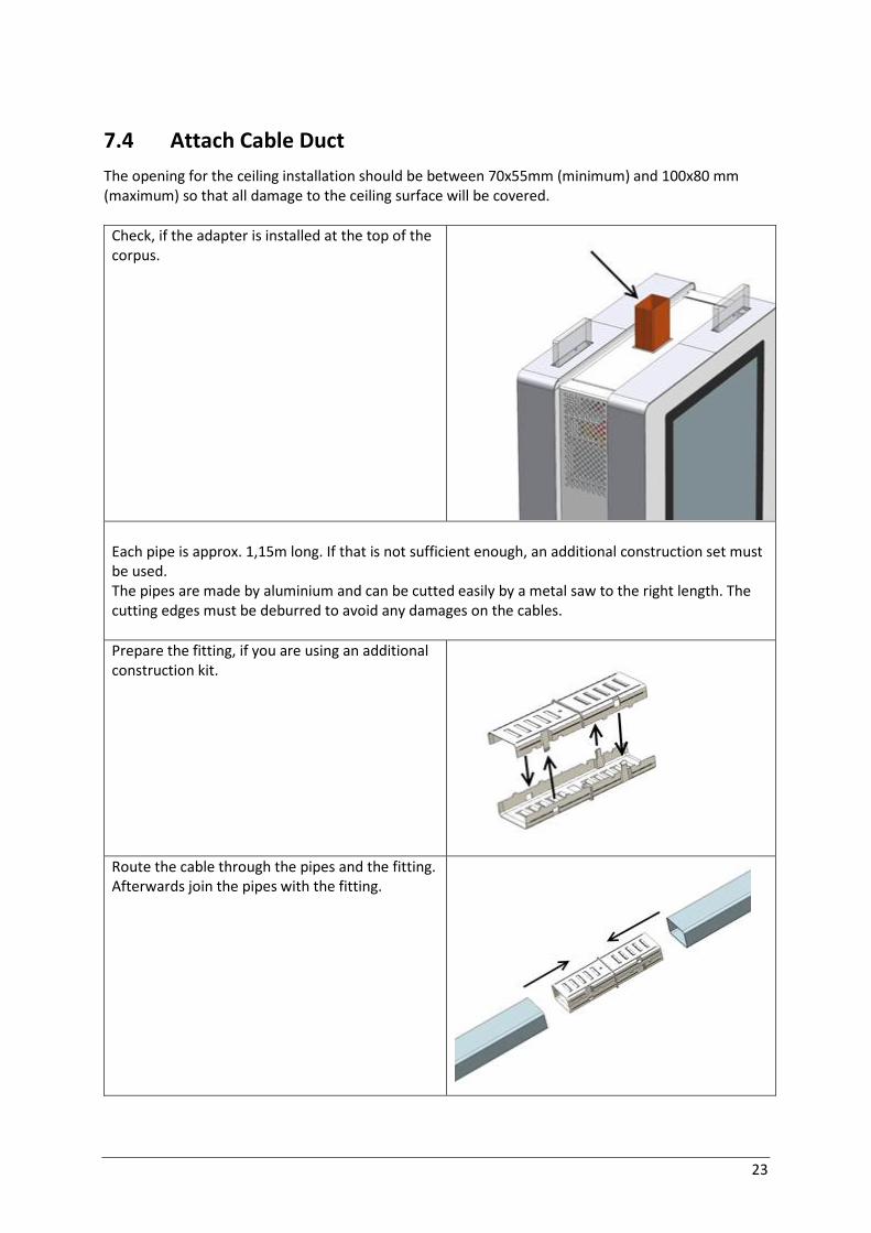
7.4 Attach Cable Duct The opening for the ceiling installation should be between 70x55mm (minimum) and 100x80 mm (maximum) so that all damage to the ceiling surface will be covered.
Check, if the adapter is installed at the top of the corpus.
Each pipe is approx. 1,15m long. If that is not sufficient enough, an additional construction set must be used. The pipes are made by aluminium and can be cutted easily by a metal saw to the right length. The cutting edges must be deburred to avoid any damages on the cables. Prepare the fitting, if you are using an additional construction kit.
Route the cable through the pipes and the fitting. Afterwards join the pipes with the fitting.

24
Attach the cover plate to the upper end of the pipe.
Attach the pipe to the adapter from above.

25
Fix the upper end of the “ceiling cabeling kit” securely on the ceiling or a prepared solid con-struction by the retaining bracket.
Due to safety reasons, the attachment of the retaining bracket to the ceiling is a mandatory requirement. The correspond-ing attachment holes are present in the retaining bracket. Additional attachment material must be procured on-site.

26
8 EFT (Electronic-Funds-Transfer)-Terminal
Power down the system. Open the device (Section "Opening the kiosk door”) and seperate complete-ly the system from the mains voltage.
Various, customer-specific EFTs are used.
Here in the example it is the IPP350. Remove the two screws (see arrows).
Remove the bracket, including the support plate. Loosen the two screws.
EFT-support plate
EFT-bracket

27
Screw the support plate at your EFT terminal, here for example an IPP350 EFT.
Hook the EFT support plate into the EFT mount at the bottom.
Connect both with a supplied locking screw.
Replace the two screws and tighten them.
Thread the connection cable through the opening and attach the EFT incl. Bracket. Screw the EFT incl. Bracket / support plate to the housing.
28
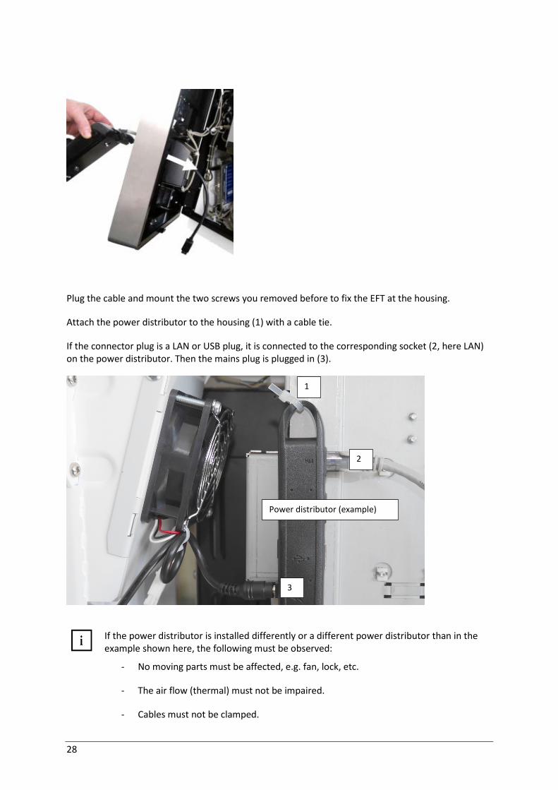
Plug the cable and mount the two screws you removed before to fix the EFT at the housing.
Attach the power distributor to the housing (1) with a cable tie.
If the connector plug is a LAN or USB plug, it is connected to the corresponding socket (2, here LAN) on the power distributor. Then the mains plug is plugged in (3).
If the power distributor is installed differently or a different power distributor than in the
example shown here, the following must be observed:
- No moving parts must be affected, e.g. fan, lock, etc.
- The air flow (thermal) must not be impaired.
- Cables must not be clamped.
1
2
3
Power distributor (example)

29
9 MX915
Power down the kiosk. Open the device and unplug the power cables of the PCs on the power distri-bution box if it is a device with fixed wiring. Otherwise, disconnect the mains plug from the housing installation.
Remove 4 nuts and uninstall the blind cover.
Set the adapter with 4 bolts into place.
Open the door and fix it with 4 nuts inside the device.

30
Set the device with the 3 key holes on the pins at the adapter.
Set the cover into place.
Fix it with the 2 screws.

31
10 Ingenico IUP/IUR 250/IUC 150 Open the door and remove the blind covers (coloured in orange) with a8x M4 socket wrench size 7.

32
10.1 Installation
i
Tighten the hexagon nuts with a torque of 1 Nm. Use a liquid threadlocker to secure the nuts!
Mounting kit
1x privacy protection left
1x privacy protection right
4x M3x8 countersunk screws
2x mounting element
12 x locking nut
4 x M4x8 cheese-head screw
2 x toothed lock washer
The fastening elements must be pushed onto the privacy flaps (see picture below).
Set the first one into place.

33
Fix it with 2 with M3x8 countersunk screw (Torx TX 10).
Fix the other one in the same way.
Set the EFT into place and fix it with 6 locking nuts. Set the card reader into place and secure it with 4 locking nuts.
EFT Card-Reader

34
Pinpad and card reader should be earthed via the pre-installed ground strap (see red lines).

35
11 Verifone UX 100/200/300 Open the door. Remove the blind covers (coloured in orange) with a8x M4 socket wrench size 7).

36
11.1 Installation
i
Tighten the hexagon nuts with a torque of 1 Nm. Use a liquid threadlocker to secure the nuts!
Mounting kit
1x privacy protection left
1x privacy protection right
4x M3x8 countersunk screws
2x mounting element
10x M4 locking nut
The fastening elements must be pushed onto the privacy flaps (see picture below).
Set the first one into place.
37
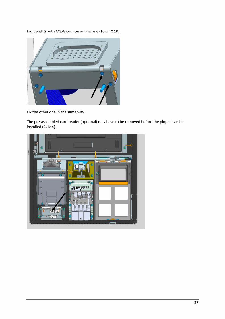
Fix it with 2 with M3x8 countersunk screw (Torx TX 10).
Fix the other one in the same way.
The pre-assembled card reader (optional) may have to be removed before the pinpad can be installed (4x M4).

38
Set the verifone into place and fix it. Do it the same way with the card reader.
Pinpad and card reader should be earthed via the pre-installed ground strap (see red lines).

39
12 CCV C60 Open the door. Remove the blind covers (coloured in orange) with a 8x M4 socket wrench size 7.
40
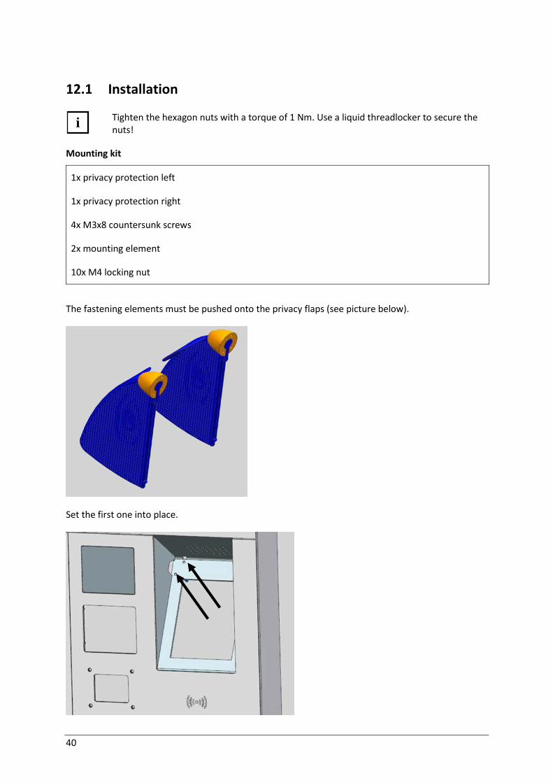
12.1 Installation
i
Tighten the hexagon nuts with a torque of 1 Nm. Use a liquid threadlocker to secure the nuts!
Mounting kit
1x privacy protection left
1x privacy protection right
4x M3x8 countersunk screws
2x mounting element
10x M4 locking nut
The fastening elements must be pushed onto the privacy flaps (see picture below).
Set the first one into place.

41
Fix it with 2 with M3x8 countersunk screw (Torx TX 10).
Fix the other one in the same way.
Set the EFT into place and fix it with 4 M3x8 countersunk screws. Install the card reader with 4 countersunk screws.

42
Pinpad and card reader should be earthed via the pre-installed ground strap (see red lines).

43
13 Start up the System
Ensure that the K-two has been installed correctly to the house installation and the LAN cable is properly connected.
The system will start up automatically, when it will be provided with current. If this does not
work, please open the device (see chapter Opening) and push the ON/OFF button at the PC to switch the system on (see arrow).
PC
Ensure that the device has been installed correctly to the house installation and the LAN cable is properly connected.
A 16A fuse complying with IEC60127 (breaking capacity of 1500A) must be part of the
building installation.
The power supply system must be equipped with separately guided protective earth conductors (PE). This kind of electricity system is knows as TN-S network. Do not use PEN conductors!

44
14 Disconnecting the System from the Mains
Open the device and unplug the power cables of the PCs on the power distribution box if it is a de-vice with fixed wiring. Otherwise, disconnect the mains plug from the housing installation.
45
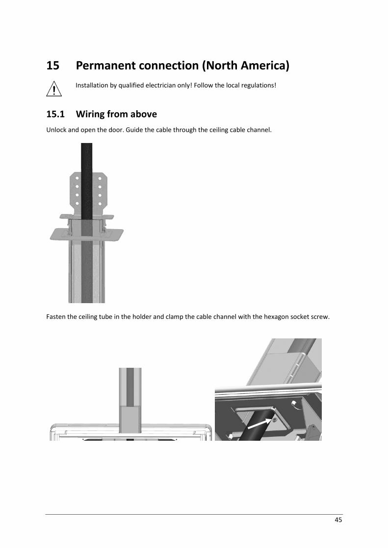
15 Permanent connection (North America)
Installation by qualified electrician only! Follow the local regulations!
15.1 Wiring from above Unlock and open the door. Guide the cable through the ceiling cable channel.
Fasten the ceiling tube in the holder and clamp the cable channel with the hexagon socket screw.
46
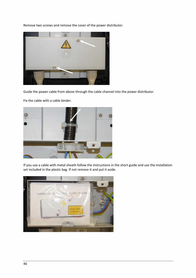
Remove two screws and remove the cover of the power distributor.
Guide the power cable from above through the cable channel into the power distributor. Fix the cable with a cable binder.
If you use a cable with metal sheath follow the instructions in the short guide and use the installation set included in the plastic bag. If not remove it and put it aside.
47
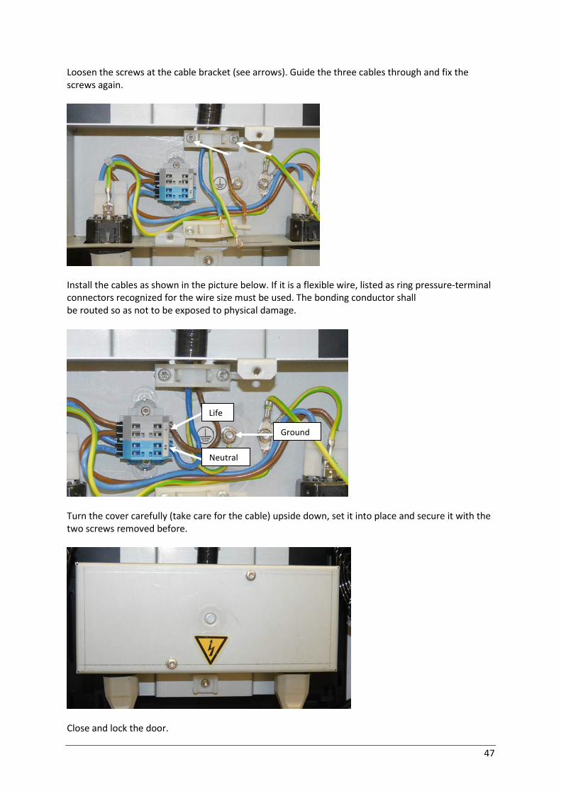
Loosen the screws at the cable bracket (see arrows). Guide the three cables through and fix the screws again.
Install the cables as shown in the picture below. If it is a flexible wire, listed as ring pressure-terminal connectors recognized for the wire size must be used. The bonding conductor shall be routed so as not to be exposed to physical damage.
Turn the cover carefully (take care for the cable) upside down, set it into place and secure it with the two screws removed before.
Close and lock the door.
Life
Neutral
Ground
48
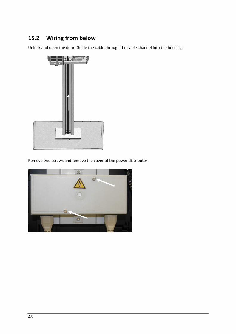
15.2 Wiring from below Unlock and open the door. Guide the cable through the cable channel into the housing.
Remove two screws and remove the cover of the power distributor.

49
Guide the cable behind the PC (1) into the distribution box and fix it with a cable binder (2).
If you use a cable with metal sheath follow the instructions in the short guide and use the installation set included in the plastic bag. If not remove it and put it aside.
1
2

50
Loosen the screws at the cable bracket (see arrows). Guide the three cables through and fix the screws again.
Install the cables as shown in the picture below. If it is a flexible wire, listed as ring pressure-terminal connectors recognized for the wire size must be used. The bonding conductor shall be routed so as not to be exposed to physical damage.
Mount the device in reverse order.
Life
Neutral
Ground
51
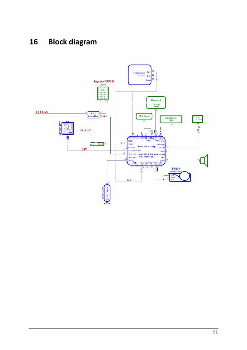
16 Block diagram

52
17 Technical data
17.1 System
Mains input voltage 100-240 V~ / 60-50Hz
Power consumption 2.4-1.0 A
Weight 22” double sided ca. 55 kg
Weight 22” single sided ca. 35 kg
Weight 27” double sided ca. 65 Kg
Weight 27” single sided ca. 40 kg
17.2 Environmental requirements Operating temperature Ambient temperature: 5° C – 35° C Humidity: 5% r.h. (1 g/m3 ) – 85% r.h. (25 g/m3 ) Temperature change: 0.5 K/min (max. 7.5K/30 min) Barometric pressure: 70 kPa – 106 kPa (70kPa corresponds to an installation at approximately 2000 meters above sea level) Installation environments with long periods of sunshine should be avoided
Storage conditions Ambient temperature: 5° C – 40° C Humidity: 5% r.h. (1 g/m3 ) – 85% r.h. (25 g/m3 ) 0.5 K/min Temperature change: 0.5 K/min (max. 7.5K/30 min) Transport conditions Ambient temperature: -25 °C – 60° C Humidity: 15% r.h. (1 g/m3 ) – 98% r.h. (32 g/m3 ) Temperature change: -25° C / 25° C

53
17.3 Electrical characteritics of the power supply Nominal voltage 2.4 – 1.0 A Mains voltage range 100 - 240 V Nominal frequency 60 / 50 Hz Network type TN Permissable tolerance for voltage range -10 % bis +6% Permissable tolerance for rated frequency ±1 %
17.4 Device conditions 110-120V 220-240 V Idle Mode Operation Idle Mode Operation Typical current consump-
tion 2,2 A 2,65 A 0,81 A 0,9 A
Active Power 154 W 220 W 150 W 295 W 110-120V Leakage Current <3,5 mA Protection class I
17.5 Noise emission in acc. withEN 27779 Noise rating according ISO 7779 Idle Mode Operation Sound power level LWAd 4 B 5 B Workplace-related sound pressure level LpAm
41 dB
51
dB
* typical operating cycle
17.6 ACO Kiosk PC
SSD 128 GB
CPU Intel i5-4570TE
Graphic Adapter VGA, resolution max. 1920x2000 Pixel @ 60 Hz

54
17.7 LCD 27” display
Size 27” TFT LCD
Maximum Resolution 1920 x 1080
Contrast Ratio 1200 :1
Brightness (Backlight Type) 300 nits (No Touch), 270 nits (Projected Capacitive)
View Angle H:178˚, V:178˚
Touch LCD Display
Touch Type Projected Capacitive
Touch points 10
Touch Screen Interface USB-HID (Type B)
I/O Port
Serial Port NA
USB Port 1 x USB 2.0 (Type B) for Touch Interface (USB-HID)
Video Port 1 x HDMI, 1 x DP, 1 x VGA
Audio Port NA
Power Input 1 x 2.1 mm 12V DC Jack
Physical Properties
Speaker NA
Construction Glass, SECC Metal
Compliance IPX1
Dimensions (W x H x D) mm 644.6 x 385.0 x 57.1 mm
Net Weight (kg) 8.09 kg
Gross Weight (kg) 9.78 kg

55
17.8 LCD 22” Touch Display
Dimensions (with base) 517.4 (W) x 313.3 (H) x 46.0 (D) mm
Net weight (approximate) 5.5 kg
Power supply 12 V DC, 4.16 A
Power consumption during operation:
45 W (normal) / standby: 3 W / off: 1 W
LCD size/ type 21.5" diagonal TFT active matrix console
Active area 476.64 (H) x 268.11 (V) mm
Pixel pitch 0.24825 (H) x 0.24825 (V) mm
Screen resolution 1920 X 1080 (max.)
Display mode
VGA 720 X 400 (70 Hz) VGA 640 X 480 (60/66/70/72/75 Hz) SVGA 800 X 600 (60/70/72/75 Hz) XGA 1024 X 768 (60/70/75 Hz) SXGA 1280 X 1024 (60/70/75 Hz) WXGA+ 1440 X 900 (60/75 Hz) WSXGA 1680 X 1050 (60 Hz) 1920 X 1080 (60 Hz)
Display color 16.7M (6 Bits + HI-FRC)
Contrast ratio 1000:1
Brightness (w/o touch) 300 cd/m² (typical)
(projected capacitive) 270 cd/m² (typical)
Response time 5 ms (typical)
Viewing angle -- Horizontal 170 (typical)
Viewing angle -- Vertical 160 (typical)
Video input format: RGB analog 0.7V
Video synchronization format Separate sync (H+V) / composite sync. / sync-on green
Video input frequency 31.47kHz ~ 82.3kHz / 56Hz ~ 75Hz (horizontal / vertical)
Video signal input D-sub 15-pin socket (analog) / DVI-D
OSD key Control key
Power On/Off, Select, Down, Up, Menu

56
OSD option Contrast, Brightness, Auto Adjust, Left / Right, Down / Up
Horizontal size
Fine, OSD Left / Right, OSD Down / Up
OSD timeout Factory Reset, Language, RGB
Plug & play DDC 2B-compatible
Conformity TÜV, CE, UL, CUL, FCC-B, RoHS
Touchscreen technology Projected capacitive
Touchscreen interface USB (Type B)
17.9 TH230+
Technology High-speed thermal printer
Resolution 8 dots/mm (203 dpi)
Printing speed Mono color: 220 mm/s, Two colors: 110 mm/s Draft mode up to 300 mm/s (reduced intensity)
Cash drawer interface 6pin RJ12, 1A@24V max.
Interface options USB 2.0 full speed, powered USB, RS232c, Ethernet
Cutter Material: hardened steel, Full cutting speed: < 300ms
Paper transport Forwards; to utilize the entire capacity of the paper > after cutting: up to 12mm backwards (approx. 3.5 lines at 7.52 lpi)
Control functions Print head temperature control with adjustment of the print speed Near end paper control and out of paper control Error message for paper cutter Printer cover open/closed Self-test with printout
Optional Paper width 57.5mm, Printing width = 51mm = 408 dots
Statistical data Total number of dots Total number of line feeds

57
Total number of cuts Max. head temperature Paper jam counter Error counter for cutter Error counter for thermistor Error counter for high voltage/low voltage Number of firmware updates Switch-on time in hours Switch-on counter
Reliability 55 million lines 3 million cuts at 55g/m² 150km at 12.5% print density
Graphics function The TH230 is fully graphic-compliant.
Paper width 79.5mm - 80mm
Paper weight 55g/m² ± 5 g/m²
Paper thickness 0.055mm – 0.1mm
Thermal coating Rear side of paper
Paper roll Outer diameter
90mm max.
Width of paper roll 80.3mm max.
Length of paper ~100m
Core size Core diameter 10mm +2mm Wall thickness of core: max. 2mm ± 0.3mm; End of paper not glued to core. Length of paper fold at core: 35mm
Print width 72mm = 576 dots

58
18 Certifications of the Manufacturer
18.1 CE Marking
The device complies with the requirements of the EU directives 2014/30/EU with regard to “Electromagnetic compatibility” and, if applicable, 2010/35/EU “Low Volt-age Directive” and 2011/65/EU "Restriction of Hazardous Substances". Therefore, you will find the CE mark on the device or packaging.
If a device is equipped with a WLAN it complies with the requirements of the “Radio Equipment Directive” 2014/53/E.
The system is approved for the USA and Canada.
Supplier's Declaration of Conformity
47 CFR § 2.1077 Compliance Information
Responsible Party in the U. S.: Diebold Nixdorf
Address: 5995 Mayfair Road N. Canton, OH 44720 / USA
Contact: [email protected]
FCC Compliance Statement
This device complies with Part 15 of the FCC Rules. Operation is subject to the following two conditions:
(1) This device may not cause harmful interference, and
(2) this device must accept any interference received, including interference that may cause undesired operation

59
19 Recycling the Kiosk
This device was designed according to the Diebold Nixdorf standard "Environmentally Conscious Product Design and Development”.
The device is manufactured without the use of CFCs and CCHs and is manufactured to a great ex-tent out of materials and components which are recyclable.
For recycling purposes do not attach any addition-al adhesive labels to the terminal.
Diebold Nixdorf disposes of old terminals in an environmentally responsible manner at a recycling center that is ISO 9001 and ISO 14001 certified, as is the entire company. Follow your local regula-tions on the disposal of toxic waste.
Your Diebold Nixdorf vendor will answer any questions you have concerning returns, recycling, and disposal of our products.


Diebold Nixdorf D-33094 Paderborn Order No.: 01750299889B