DICOM PS 3.8 2011 - Network Communication Support …dicom.nema.org/Dicom/2011/11_08pu.pdfPS...
54
- Standard - PS 3.8-2011 Digital Imaging and Communications in Medicine (DICOM) Part 8: Network Communication Support for Message Exchange Published by National Electrical Manufacturers Association 1300 N. 17th Street Rosslyn, Virginia 22209 USA © Copyright 2011 by the National Electrical Manufacturers Association. All rights including translation into other languages, reserved under the Universal Copyright Convention, the Berne Convention for the Protection of Literacy and Artistic Works, and the International and Pan American Copyright Conventions.
Transcript of DICOM PS 3.8 2011 - Network Communication Support …dicom.nema.org/Dicom/2011/11_08pu.pdfPS...

- Standard -
PS 3.8-2011
Digital Imaging and Communications in Medicine (DICOM)
Part 8: Network Communication Support for Message Exchange
Published by
National Electrical Manufacturers Association 1300 N. 17th Street Rosslyn, Virginia 22209 USA
© Copyright 2011 by the National Electrical Manufacturers Association. All rights including translation into other languages, reserved under the Universal Copyright Convention, the Berne Convention for the Protection of Literacy and Artistic Works, and the International and Pan American Copyright Conventions.
PS 3.8-2011 Page 2
- Standard -
NOTICE AND DISCLAIMER
The information in this publication was considered technically sound by the consensus of persons engaged in the development and approval of the document at the time it was developed. Consensus does not necessarily mean that there is unanimous agreement among every person participating in the development of this document.
NEMA standards and guideline publications, of which the document contained herein is one, are developed through a voluntary consensus standards development process. This process brings together volunteers and/or seeks out the views of persons who have an interest in the topic covered by this publication. While NEMA administers the process and establishes rules to promote fairness in the development of consensus, it does not write the document and it does not independently test, evaluate, or verify the accuracy or completeness of any information or the soundness of any judgments contained in its standards and guideline publications.
NEMA disclaims liability for any personal injury, property, or other damages of any nature whatsoever, whether special, indirect, consequential, or compensatory, directly or indirectly resulting from the publication, use of, application, or reliance on this document. NEMA disclaims and makes no guaranty or warranty, expressed or implied, as to the accuracy or completeness of any information published herein, and disclaims and makes no warranty that the information in this document will fulfill any of your particular purposes or needs. NEMA does not undertake to guarantee the performance of any individual manufacturer or seller’s products or services by virtue of this standard or guide.
In publishing and making this document available, NEMA is not undertaking to render professional or other services for or on behalf of any person or entity, nor is NEMA undertaking to perform any duty owed by any person or entity to someone else. Anyone using this document should rely on his or her own independent judgment or, as appropriate, seek the advice of a competent professional in determining the exercise of reasonable care in any given circumstances. Information and other standards on the topic covered by this publication may be available from other sources, which the user may wish to consult for additional views or information not covered by this publication.
NEMA has no power, nor does it undertake to police or enforce compliance with the contents of this document. NEMA does not certify, test, or inspect products, designs, or installations for safety or health purposes. Any certification or other statement of compliance with any health or safety–related information in this document shall not be attributable to NEMA and is solely the responsibility of the certifier or maker of the statement.
PS 3.8-2009 Page 3
- Standard -
Table of Contents
NOTICE AND DISCLAIMER......................................................................................................................... 2 FOREWORD................................................................................................................................................. 5 1 Scope and field of application................................................................................................................. 6 2 Normative references ............................................................................................................................. 6
2.1 INTERNATIONAL STANDARDS .................................................................................................. 6 2.2 OTHER DOCUMENTS ................................................................................................................. 7
3 Definitions ............................................................................................................................................... 8 3.1 REFERENCE MODEL DEFINITIONS .......................................................................................... 8 3.2 NAMING AND ADDRESSING DEFINITIONS .............................................................................. 8 3.3 SERVICE CONVENTIONS DEFINITIONS................................................................................... 8 3.4 PRESENTATION SERVICE DEFINITIONS ................................................................................. 9 3.5 ACSE SERVICE DEFINITIONS.................................................................................................... 9 3.6 DICOM INTRODUCTION AND OVERVIEW DEFINITION........................................................... 9 3.7 DICOM COMMUNICATION SUPPORT DEFINITIONS ............................................................... 9
4 Symbols and abbreviations .................................................................................................................... 9 5 Conventions.......................................................................................................................................... 10 6 Network communication support environment ..................................................................................... 11 7 OSI upper layer service for DICOM application entities ....................................................................... 13
7.1 A-ASSOCIATE SERVICE ........................................................................................................... 13 7.1.1 A-ASSOCIATE PARAMETERS......................................................................................... 14 7.1.2 A-ASSOCIATE SERVICE PROCEDURE ......................................................................... 18
7.2 A-RELEASE SERVICE ............................................................................................................... 19 7.2.1 A-RELEASE PARAMETERS............................................................................................. 19 7.2.2 A-RELEASE SERVICE PROCEDURE ............................................................................. 20
7.3 A-ABORT SERVICE ................................................................................................................... 21 7.3.1 A-ABORT PARAMETERS................................................................................................. 21 7.3.2 A-ABORT SERVICE PROCEDURE.................................................................................. 21
7.4 A-P-ABORT SERVICE................................................................................................................ 22 7.4.1 A-P-ABORT PARAMETER................................................................................................ 22 7.4.2 A-P-ABORT SERVICE PROCEDURE .............................................................................. 23
7.5 SEQUENCING INFORMATION.................................................................................................. 23 7.6 P-DATA SERVICE ...................................................................................................................... 23
7.6.1 P-DATA PARAMETERS.................................................................................................... 23 8 Retired ................................................................................................................................................. 24 9 DICOM upper layer protocol for TCP/IP .................................................................................................. 24
9.1 USE OF THE TRANSPORT SERVICE PROVIDED BY TCP .................................................... 24 9.1.1 GENERAL.......................................................................................................................... 24 9.1.2 OPENING A TCP TRANSPORT CONNECTION.............................................................. 25 9.1.3 TRANSFERRING DATA ON A TCP CONNECTION ........................................................ 25 9.1.4 CLOSING A TCP TRANSPORT CONNECTION .............................................................. 25 9.1.5 ARTIM TIMER ................................................................................................................... 26
9.2 DICOM UPPER LAYER PROTOCOL FOR TCP/IP STATE MACHINE..................................... 26 9.2.1 MACHINE STATES DEFINITION..................................................................................... 26 9.2.2 STATE MACHINE ACTIONS DEFINITION....................................................................... 27

PS 3.8-2011 Page 4
- Standard -
9.2.3 DICOM UPPER LAYER PROTOCOL FOR TCP/IP STATE TRANSITION TABLE............. 28 9.3 DICOM UPPER LAYER PROTOCOL FOR TCP/IP DATA UNITS STRUCTURE ..................... 29
9.3.1 GENERAL......................................................................................................................... 29 9.3.2 A-ASSOCIATE-RQ PDU STRUCTURE........................................................................... 32 9.3.3 A-ASSOCIATE-AC PDU STRUCTURE ........................................................................... 36 9.3.4 A-ASSOCIATE-RJ PDU STRUCTURE............................................................................ 38 9.3.5 P-DATA-TF PDU STRUCTURE....................................................................................... 39 9.3.6 A-RELEASE-RQ PDU STRUCTURE............................................................................... 40 9.3.7 A-RELEASE-RP PDU STRUCTURE ............................................................................... 41 9.3.8 A-ABORT PDU STRUCTURE.......................................................................................... 41
10 Conformance ........................................................................................................................................ 42 10.1 CONFORMANCE REQUIREMENTS ...................................................................................... 42
10.1.1 Retired.............................................................................................................................. 42 10.1.2 TCP/IP NETWORK COMMUNICATION SUPPORT ....................................................... 42
10.2 CONFORMANCE STATEMENT............................................................................................... 43 Annex A Application context names (Informative) ................................................................................. 44
A.1 APPLICATION CONTEXT DEFINITION .................................................................................... 44 A.2 DICOM APPLICATION CONTEXT NAME ENCODING AND REGISTRATION........................ 44
A.2.1 DICOM registered application context names .................................................................. 44 A.2.2 Retired............................................................................................................................... 44
Annex B Abstract and transfer syntaxes (Informative) .......................................................................... 45 B.1 ABSTRACT SYNTAX DEFINITION............................................................................................ 45 B.2 TRANSFER SYNTAX DEFINITION ........................................................................................... 45 B.3 DICOM ABSTRACT AND TRANSFER SYNTAX NAMES ENCODING AND REGISTRATION45
B.3.1 DICOM registered abstract and transfer syntax names.................................................... 45 B.3.2 Privately defined abstract and transfer syntax names ...................................................... 45
Annex C DICOM addressing (Normative) .............................................................................................. 46 C.1 DICOM APPLICATION ENTITY TITLES.................................................................................... 46 C.2 NAMING AND ADDRESSING USAGE RULES......................................................................... 46
Annex D Use and format of the A-ASSOCIATE user information parameter (Normative) .................... 47 D.1 MAXIMUM LENGTH NEGOTIATION......................................................................................... 47
D.1.1 Maximum length sub-item structure (A-ASSOCIATE-RQ) ............................................... 47 D.1.2 Maximum length sub-item structure (A-ASSOCIATE-AC)................................................ 47
D.2 EXTENDED USER INFORMATION NEGOTIATION................................................................. 48 Annex E Usage of the P-DATA service by the DICOM application entity (Normative) ......................... 49
E.1 ENCAPSULATION RULES ........................................................................................................ 49 E.2 MESSAGE CONTROL HEADER ENCODING........................................................................... 50
Annex F DICOM UL encoding rules for application contexts, abstract syntaxes, transfer syntaxes .... 51 F.1 ENCODING RULES.................................................................................................................... 51
Annex G Overview of the OSI layer and services concepts (Informative) ............................................. 52 Annex H Index of Item and PDU Types (Informative) ............................................................................ 54

PS 3.8-2009 Page 5
- Standard -
FOREWORD
This DICOM Standard was developed according to the procedures of the DICOM Standards Committee.
The DICOM Standard is structured as a multi-part document using the guidelines established in the following document:
ISO/IEC Directives, 1989 Part 3: Drafting and presentation of International Standards.
PS 3.1 should be used as the base reference for the current parts of this Standard.
PS 3.8-2011 Page 6
- Standard -
1 Scope and field of application
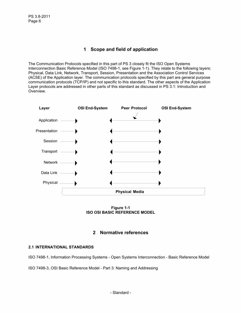
The Communication Protocols specified in this part of PS 3 closely fit the ISO Open Systems Interconnection Basic Reference Model (ISO 7498-1, see Figure 1-1). They relate to the following layers: Physical, Data Link, Network, Transport, Session, Presentation and the Association Control Services (ACSE) of the Application layer. The communication protocols specified by this part are general purpose communication protocols (TCP/IP) and not specific to this standard. The other aspects of the Application Layer protocols are addressed in other parts of this standard as discussed in PS 3.1: Introduction and Overview.
Application
Presentation
Session
Transport
Network
Data Link
Physical
Physical Media
Layer OSI End-System OSI End-SystemPeer Protocol
Figure 1-1 ISO OSI BASIC REFERENCE MODEL
2 Normative references
2.1 INTERNATIONAL STANDARDS
ISO 7498-1, Information Processing Systems - Open Systems Interconnection - Basic Reference Model
ISO 7498-3, OSI Basic Reference Model - Part 3: Naming and Addressing
PS 3.8-2009 Page 7
- Standard -
ISO 8327:1987, Information Processing Systems - Open Systems Interconnection - Connection Oriented Session Protocol Specification
ISO 8327/AM 2, Information Processing Systems - Open Systems Interconnection - Connection Oriented Session Protocol Specification - Amendment 2: Incorporation of Unlimited User Data
ISO 8649:1987, Information Processing Systems - Open Systems Interconnection - Service Definition for the Association Control Service Element
ISO 8650:1987, Information Processing Systems - Open Systems Interconnection - Protocol Specification for the Association Control Service Element
ISO TR 8509, Information Processing Systems - Open Systems Interconnection - Service Conventions
ISO 8822:1988, Information Processing Systems - Open Systems Interconnection - Connection-Oriented Presentation Service Definition
ISO 8823:1988, Information Processing Systems - Open Systems Interconnection - Connection Oriented Presentation Protocol Specification
ISO 8824:1990, Information Processing Systems - Open Systems Interconnection - Specification of Abstract Syntax Notation One (ASN.1)
ISO 8825:1990, Information Processing Systems - Open Systems Interconnection - Specification of Basic Encoding Rules for Abstract Syntax Notation One (ASN.1)
ISO/IEC 9545, Information Processing Systems - Open Systems Interconnection - Application Layer Structure
ISO/IEC 9834-1, Information technology - Open Systems Interconnection - Procedures for the operation of OSI Registration Authorities: General procedures and top arcs of the ASN.1 Object Identifier tree
ISO/IEC TR 10000-1, Information Processing Systems - Open Systems Interconnection - International Standardized Profiles, Part 1: Taxonomy Framework
2.2 OTHER DOCUMENTS
NIST Special Publication 500-150 - Stable Implementation Agreements for Open Systems Interconnection Protocols
RFC 791, Internet Protocol - DARPA Internet Protocol Specification
RFC 792, Internet Control Message Protocol - DARPA Internet Program Protocol Specification
RFC 793, Transmission Control Program - DARPA Internet Protocol Specification
RFC 950, Internet Subnetting
RFC 1881, IPv6 Address Allocation Management

PS 3.8-2011 Page 8
- Standard -
RFC 2460, Internet Protocol, Version 6 (IPv6) Specification
3 Definitions
3.1 REFERENCE MODEL DEFINITIONS
This part of the Standard is based on the concepts developed in ISO 7498-1 and makes use of the following terms defined in it:
a) application entity b) application layer c) application process d) data link layer e) layer entity f) network layer g) physical layer h) presentation layer i) presentation service j) protocol or layer protocol k) protocol data unit or layer protocol data unit l) service or layer service m) service access point n) session layer o) transfer syntax p) transport layer q) transport protocol r) transport connection
3.2 NAMING AND ADDRESSING DEFINITIONS
This part of the Standard makes use of the following terms defined in ISO 7498-3:
a) calling presentation address b) called presentation address c) responding presentation address d) called application entity title e) calling application entity title
3.3 SERVICE CONVENTIONS DEFINITIONS
This part of the Standard makes use of the following terms defined in ISO/TR 8509:
a) service provider b) service user c) confirmed service d) non-confirmed service
PS 3.8-2009 Page 9
- Standard -
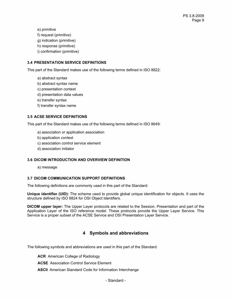
e) primitive f) request (primitive) g) indication (primitive) h) response (primitive) i) confirmation (primitive)
3.4 PRESENTATION SERVICE DEFINITIONS
This part of the Standard makes use of the following terms defined in ISO 8822:
a) abstract syntax b) abstract syntax name c) presentation context d) presentation data values e) transfer syntax f) transfer syntax name
3.5 ACSE SERVICE DEFINITIONS
This part of the Standard makes use of the following terms defined in ISO 8649:
a) association or application association b) application context c) association control service element d) association initiator
3.6 DICOM INTRODUCTION AND OVERVIEW DEFINITION
a) message
3.7 DICOM COMMUNICATION SUPPORT DEFINITIONS
The following definitions are commonly used in this part of the Standard:
Unique identifier (UID): The scheme used to provide global unique identification for objects. It uses the structure defined by ISO 8824 for OSI Object Identifiers.
DICOM upper layer: The Upper Layer protocols are related to the Session, Presentation and part of the Application Layer of the ISO reference model. These protocols provide the Upper Layer Service. This Service is a proper subset of the ACSE Service and OSI Presentation Layer Service.
4 Symbols and abbreviations
The following symbols and abbreviations are used in this part of the Standard.
ACR American College of Radiology
ACSE Association Control Service Element
ASCII American Standard Code for Information Interchange
PS 3.8-2011 Page 10
- Standard -
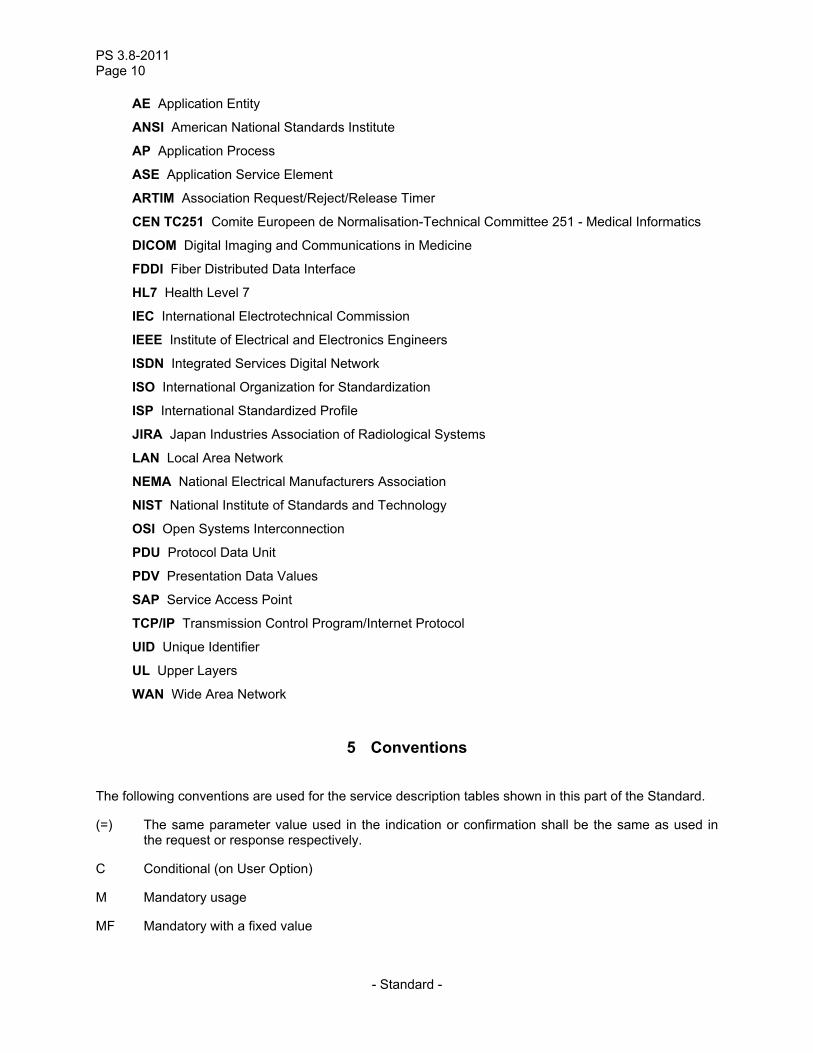
AE Application Entity
ANSI American National Standards Institute
AP Application Process
ASE Application Service Element
ARTIM Association Request/Reject/Release Timer
CEN TC251 Comite Europeen de Normalisation-Technical Committee 251 - Medical Informatics
DICOM Digital Imaging and Communications in Medicine
FDDI Fiber Distributed Data Interface
HL7 Health Level 7
IEC International Electrotechnical Commission
IEEE Institute of Electrical and Electronics Engineers
ISDN Integrated Services Digital Network
ISO International Organization for Standardization
ISP International Standardized Profile
JIRA Japan Industries Association of Radiological Systems
LAN Local Area Network
NEMA National Electrical Manufacturers Association
NIST National Institute of Standards and Technology
OSI Open Systems Interconnection
PDU Protocol Data Unit
PDV Presentation Data Values
SAP Service Access Point
TCP/IP Transmission Control Program/Internet Protocol
UID Unique Identifier
UL Upper Layers
WAN Wide Area Network
5 Conventions
The following conventions are used for the service description tables shown in this part of the Standard.
(=) The same parameter value used in the indication or confirmation shall be the same as used in the request or response respectively.
C Conditional (on User Option)
M Mandatory usage
MF Mandatory with a fixed value
PS 3.8-2009 Page 11
- Standard -
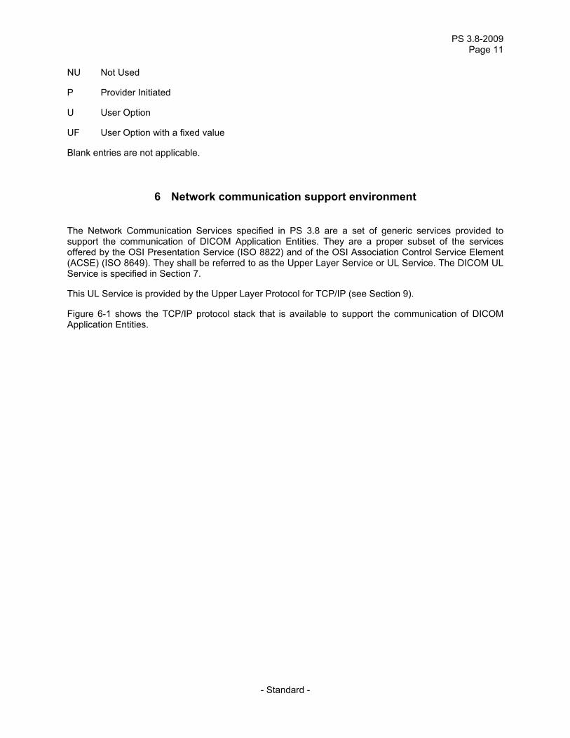
NU Not Used
P Provider Initiated
U User Option
UF User Option with a fixed value
Blank entries are not applicable.
6 Network communication support environment
The Network Communication Services specified in PS 3.8 are a set of generic services provided to support the communication of DICOM Application Entities. They are a proper subset of the services offered by the OSI Presentation Service (ISO 8822) and of the OSI Association Control Service Element (ACSE) (ISO 8649). They shall be referred to as the Upper Layer Service or UL Service. The DICOM UL Service is specified in Section 7.
This UL Service is provided by the Upper Layer Protocol for TCP/IP (see Section 9).
Figure 6-1 shows the TCP/IP protocol stack that is available to support the communication of DICOM Application Entities.

PS 3.8-2011 Page 12
- Standard -
DICOM Application Message Exchange
Medical Imaging Application
DICOMUpper Layer
Protocolfor
TCP/IP
TCP/IP
Network
UpperLayer
ServiceBoundary
Figure 6-1 DICOM NETWORK PROTOCOL ARCHITECTURE

PS 3.8-2009 Page 13
- Standard -
7 OSI upper layer service for DICOM application entities
This section provides a description of how to use the OSI Association Control Service Element (ACSE) and OSI Presentation Layer to provide the Upper Layer Service necessary to support the communication of DICOM Application Entities. This Upper Layer Service is a fully conformant subset of the services offered by the ACSE and the OSI Presentation Layer.
The UL Services are listed in Table 7-1.
Table 7-1 UPPER LAYER SERVICES
SERVICE TYPE A-ASSOCIATE Confirmed A-RELEASE Confirmed A-ABORT Non-Confirmed A-P-ABORT Provider-initiated P-DATA Non-Confirmed
In addition to the Upper Layer Service specification, this section defines at the parameter level the use of each element of this Upper Layer Service by DICOM Application Entities. The rules guiding the use of this Upper Layer Service by the DICOM Application Entities are addressed in PS 3.7.
7.1 A-ASSOCIATE SERVICE
The establishment of an association between two AEs shall be performed through ACSE A-ASSOCIATE request, indication, response and confirmation primitives. The initiator of the service is hereafter called a requestor and the service-user which receives the A-ASSOCIATE indication is hereafter called the acceptor. It shall be a confirmed service.
Note: The A-ASSOCIATE service supports the equivalent of a channel establishment in a point-to-point interface (See PS 3.9).
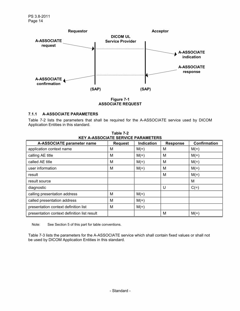
Figure 7-1 illustrates the association establishment between two AEs.
PS 3.8-2011 Page 14
- Standard -
Requestor Acceptor DICOM UL
Service Provider
(SAP) (SAP)
A-ASSOCIATE request
A-ASSOCIATE confirmation
A-ASSOCIATE response
A-ASSOCIATE indication
Figure 7-1 ASSOCIATE REQUEST
7.1.1 A-ASSOCIATE PARAMETERS Table 7-2 lists the parameters that shall be required for the A-ASSOCIATE service used by DICOM Application Entities in this standard.
Table 7-2 KEY A-ASSOCIATE SERVICE PARAMETERS
A-ASSOCIATE parameter name Request Indication Response Confirmation application context name M M(=) M M(=) calling AE title M M(=) M M(=) called AE title M M(=) M M(=) user information M M(=) M M(=) result M M(=) result source M diagnostic U C(=) calling presentation address M M(=) called presentation address M M(=) presentation context definition list M M(=) presentation context definition list result M M(=)
Note: See Section 5 of this part for table conventions.
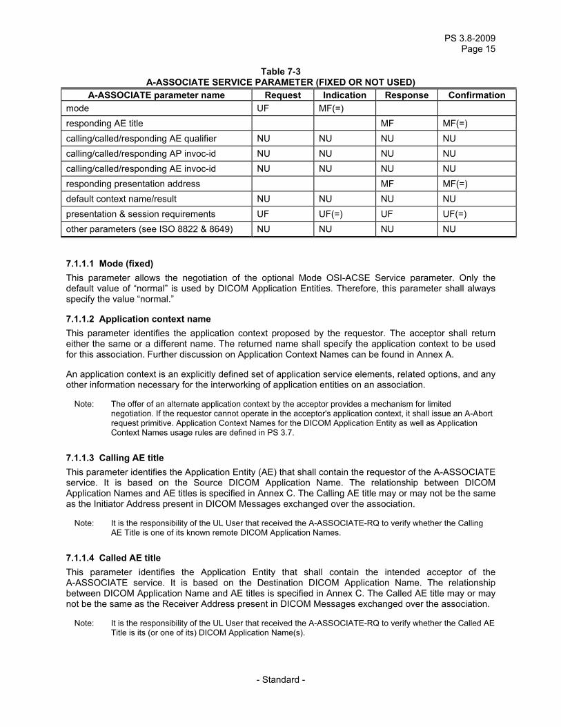
Table 7-3 lists the parameters for the A-ASSOCIATE service which shall contain fixed values or shall not be used by DICOM Application Entities in this standard.
PS 3.8-2009 Page 15
- Standard -
Table 7-3 A-ASSOCIATE SERVICE PARAMETER (FIXED OR NOT USED)
A-ASSOCIATE parameter name Request Indication Response Confirmation mode UF MF(=) responding AE title MF MF(=) calling/called/responding AE qualifier NU NU NU NU calling/called/responding AP invoc-id NU NU NU NU calling/called/responding AE invoc-id NU NU NU NU responding presentation address MF MF(=) default context name/result NU NU NU NU presentation & session requirements UF UF(=) UF UF(=) other parameters (see ISO 8822 & 8649) NU NU NU NU
7.1.1.1 Mode (fixed) This parameter allows the negotiation of the optional Mode OSI-ACSE Service parameter. Only the default value of “normal” is used by DICOM Application Entities. Therefore, this parameter shall always specify the value “normal.”
7.1.1.2 Application context name This parameter identifies the application context proposed by the requestor. The acceptor shall return either the same or a different name. The returned name shall specify the application context to be used for this association. Further discussion on Application Context Names can be found in Annex A.
An application context is an explicitly defined set of application service elements, related options, and any other information necessary for the interworking of application entities on an association.
Note: The offer of an alternate application context by the acceptor provides a mechanism for limited negotiation. If the requestor cannot operate in the acceptor's application context, it shall issue an A-Abort request primitive. Application Context Names for the DICOM Application Entity as well as Application Context Names usage rules are defined in PS 3.7.
7.1.1.3 Calling AE title This parameter identifies the Application Entity (AE) that shall contain the requestor of the A-ASSOCIATE service. It is based on the Source DICOM Application Name. The relationship between DICOM Application Names and AE titles is specified in Annex C. The Calling AE title may or may not be the same as the Initiator Address present in DICOM Messages exchanged over the association.
Note: It is the responsibility of the UL User that received the A-ASSOCIATE-RQ to verify whether the Calling AE Title is one of its known remote DICOM Application Names.
7.1.1.4 Called AE title This parameter identifies the Application Entity that shall contain the intended acceptor of the A-ASSOCIATE service. It is based on the Destination DICOM Application Name. The relationship between DICOM Application Name and AE titles is specified in Annex C. The Called AE title may or may not be the same as the Receiver Address present in DICOM Messages exchanged over the association.
Note: It is the responsibility of the UL User that received the A-ASSOCIATE-RQ to verify whether the Called AE Title is its (or one of its) DICOM Application Name(s).
PS 3.8-2011 Page 16
- Standard -
7.1.1.5 Responding AE title (fixed) This parameter identifies the AE that shall contain the actual acceptor of the A-ASSOCIATE service. In this standard it shall always contain the same value as the Called AE Title of the A-ASSOCIATE indication.
7.1.1.6 User information This parameter shall be used by the requestor and the acceptor of the association to include DICOM Application Entity user information. Its meaning shall depend on the application context that accompanies the primitive. The usage of this parameter is specified in Annex D.
Notes: 1. This parameter is used to carry initialization information for the DICOM Application Entities as defined in the application context specified by the value of the accompanying Application Context Name parameter.
2. Annex D specifies some user information sub-items, and references PS3.7 for the specification of additional sub-items. PS3.7, in turn, references PS3.4 for the specification of Service-class-application-information used in some sub-items.
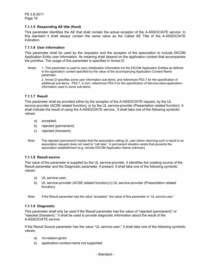
7.1.1.7 Result This parameter shall be provided either by the acceptor of the A-ASSOCIATE request, by the UL service-provider (ACSE related function), or by the UL service-provider (Presentation related function). It shall indicate the result of using the A-ASSOCIATE service. It shall take one of the following symbolic values:
a) accepted; b) rejected (permanent); c) rejected (transient).
Note: The rejected (permanent) implies that the association calling UL user (when returning such a result to an association request) does not need to “call later.” A permanent situation exists that prevents the association establishment (e.g. remote DICOM Application Name unknown).
7.1.1.8 Result source The value of the parameter is supplied by the UL service-provider. It identifies the creating source of the Result parameter and the Diagnostic parameter, if present. It shall take one of the following symbolic values:
a) UL service-user; b) UL service-provider (ACSE related function);c) UL service-provider (Presentation related
function).
Note: If the Result parameter has the value “accepted,” the value of this parameter is “UL service-user.”
7.1.1.9 Diagnostic This parameter shall only be used if the Result parameter has the value of “rejected (permanent)” or “rejected (transient).” It shall be used to provide diagnostic information about the result of the A-ASSOCIATE service.
If the Result Source parameter has the value “UL service-user,” it shall take one of the following symbolic values:
a) no-reason-given b) application-context-name not supported
PS 3.8-2009 Page 17
- Standard -
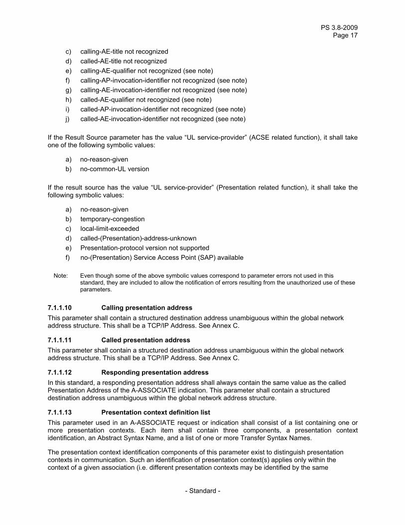
c) calling-AE-title not recognized d) called-AE-title not recognized e) calling-AE-qualifier not recognized (see note) f) calling-AP-invocation-identifier not recognized (see note) g) calling-AE-invocation-identifier not recognized (see note) h) called-AE-qualifier not recognized (see note) i) called-AP-invocation-identifier not recognized (see note) j) called-AE-invocation-identifier not recognized (see note)
If the Result Source parameter has the value “UL service-provider” (ACSE related function), it shall take one of the following symbolic values:
a) no-reason-given b) no-common-UL version
If the result source has the value “UL service-provider” (Presentation related function), it shall take the following symbolic values:
a) no-reason-given b) temporary-congestion c) local-limit-exceeded d) called-(Presentation)-address-unknown e) Presentation-protocol version not supported f) no-(Presentation) Service Access Point (SAP) available
Note: Even though some of the above symbolic values correspond to parameter errors not used in this
standard, they are included to allow the notification of errors resulting from the unauthorized use of these parameters.
7.1.1.10 Calling presentation address This parameter shall contain a structured destination address unambiguous within the global network address structure. This shall be a TCP/IP Address. See Annex C.
7.1.1.11 Called presentation address This parameter shall contain a structured destination address unambiguous within the global network address structure. This shall be a TCP/IP Address. See Annex C.
7.1.1.12 Responding presentation address In this standard, a responding presentation address shall always contain the same value as the called Presentation Address of the A-ASSOCIATE indication. This parameter shall contain a structured destination address unambiguous within the global network address structure.
7.1.1.13 Presentation context definition list This parameter used in an A-ASSOCIATE request or indication shall consist of a list containing one or more presentation contexts. Each item shall contain three components, a presentation context identification, an Abstract Syntax Name, and a list of one or more Transfer Syntax Names.
The presentation context identification components of this parameter exist to distinguish presentation contexts in communication. Such an identification of presentation context(s) applies only within the context of a given association (i.e. different presentation contexts may be identified by the same
PS 3.8-2011 Page 18
- Standard -
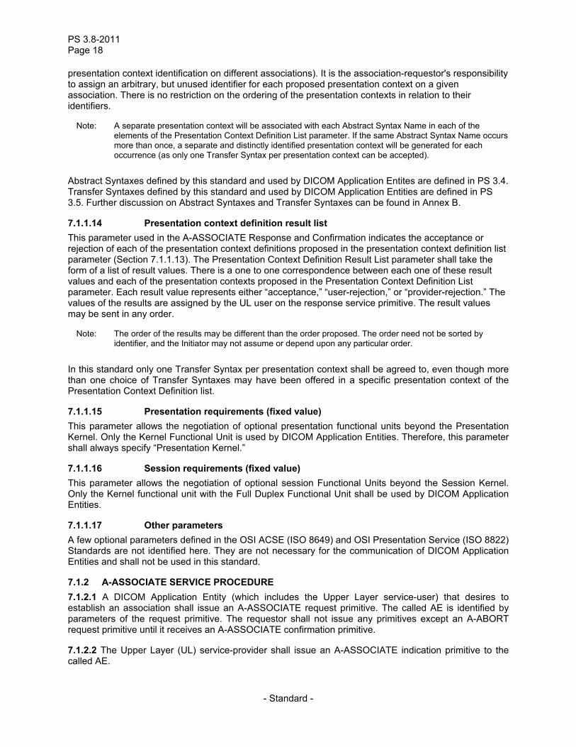
presentation context identification on different associations). It is the association-requestor's responsibility to assign an arbitrary, but unused identifier for each proposed presentation context on a given association. There is no restriction on the ordering of the presentation contexts in relation to their identifiers.
Note: A separate presentation context will be associated with each Abstract Syntax Name in each of the elements of the Presentation Context Definition List parameter. If the same Abstract Syntax Name occurs more than once, a separate and distinctly identified presentation context will be generated for each occurrence (as only one Transfer Syntax per presentation context can be accepted).
Abstract Syntaxes defined by this standard and used by DICOM Application Entites are defined in PS 3.4. Transfer Syntaxes defined by this standard and used by DICOM Application Entities are defined in PS 3.5. Further discussion on Abstract Syntaxes and Transfer Syntaxes can be found in Annex B.
7.1.1.14 Presentation context definition result list This parameter used in the A-ASSOCIATE Response and Confirmation indicates the acceptance or rejection of each of the presentation context definitions proposed in the presentation context definition list parameter (Section 7.1.1.13). The Presentation Context Definition Result List parameter shall take the form of a list of result values. There is a one to one correspondence between each one of these result values and each of the presentation contexts proposed in the Presentation Context Definition List parameter. Each result value represents either “acceptance,” “user-rejection,” or “provider-rejection.” The values of the results are assigned by the UL user on the response service primitive. The result values may be sent in any order.
Note: The order of the results may be different than the order proposed. The order need not be sorted by identifier, and the Initiator may not assume or depend upon any particular order.
In this standard only one Transfer Syntax per presentation context shall be agreed to, even though more than one choice of Transfer Syntaxes may have been offered in a specific presentation context of the Presentation Context Definition list.
7.1.1.15 Presentation requirements (fixed value) This parameter allows the negotiation of optional presentation functional units beyond the Presentation Kernel. Only the Kernel Functional Unit is used by DICOM Application Entities. Therefore, this parameter shall always specify “Presentation Kernel.”
7.1.1.16 Session requirements (fixed value) This parameter allows the negotiation of optional session Functional Units beyond the Session Kernel. Only the Kernel functional unit with the Full Duplex Functional Unit shall be used by DICOM Application Entities.
7.1.1.17 Other parameters A few optional parameters defined in the OSI ACSE (ISO 8649) and OSI Presentation Service (ISO 8822) Standards are not identified here. They are not necessary for the communication of DICOM Application Entities and shall not be used in this standard.
7.1.2 A-ASSOCIATE SERVICE PROCEDURE 7.1.2.1 A DICOM Application Entity (which includes the Upper Layer service-user) that desires to establish an association shall issue an A-ASSOCIATE request primitive. The called AE is identified by parameters of the request primitive. The requestor shall not issue any primitives except an A-ABORT request primitive until it receives an A-ASSOCIATE confirmation primitive.
7.1.2.2 The Upper Layer (UL) service-provider shall issue an A-ASSOCIATE indication primitive to the called AE.
PS 3.8-2009 Page 19
- Standard -
7.1.2.3 The called AE shall accept or reject the association by sending an A-ASSOCIATE response primitive with an appropriate Result parameter. The Upper layer service-provider shall issue an A-ASSOCIATE confirmation primitive having the same Result parameter. The Result Source parameter shall be assigned the symbolic value of “UL service-user.”
7.1.2.4 If the acceptor accepts the association, the association is available for use. Both AEs may now use any service provided by the DICOM application context that is in effect (with the exception of A-ASSOCIATE).
Note: This implies that once the association has been established, DICOM Messages can be exchanged as defined in PS 3.7.
7.1.2.5 If the called AE rejects the association, the association shall not be established.
7.1.2.6 The UL service-provider may not be capable of supporting the requested association. In this situation, it shall return an A-ASSOCIATE confirmation primitive to the requestor with an appropriate Result parameter (rejected). The Result Source parameter shall be appropriately assigned either the symbolic value of “UL service-provider (ACSE related function)” or “UL service-provider (Presentation related function).” The indication primitive shall not be issued. The association shall not be established.
7.1.2.7 Either an association-requestor or acceptor may disrupt the A-ASSOCIATE service procedure by issuing an A-ABORT request primitive (see Section 7.3). The remote AE receives an A-ABORT indication primitive. The association shall not be established.
7.2 A-RELEASE SERVICE
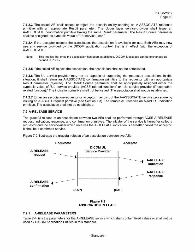
The graceful release of an association between two AEs shall be performed through ACSE A-RELEASE request, indication, response, and confirmation primitives. The initiator of the service is hereafter called a requestor and the service-user which receives the A-RELEASE indication is hereafter called the acceptor. It shall be a confirmed service.
Figure 7-2 illustrates the graceful release of an association between two AEs.
Requestor Acceptor DICOM UL
Service Provider
(SAP) (SAP)
A-RELEASE request
A-RELEASE confirmation
A-RELEASE response
A-RELEASE indication
Figure 7-2 ASSOCIATION RELEASE
7.2.1 A-RELEASE PARAMETERS Table 7-4 lists the parameters for the A-RELEASE service which shall contain fixed values or shall not be used by DICOM Application Entities in this standard.
PS 3.8-2011 Page 20
- Standard -
Table 7-4 A-RELEASE SERVICE PARAMETERS
A-RELEASE parameter name Request Indication Response Confirmation
reason UF UF(=) UF UF(=) user information NU NU(=) NU NU(=) result MF MF(=)
7.2.1.1 Reason (fixed) When used on the request primitive, this parameter identifies the general level of urgency of the request. This parameter shall always use the value “normal” in this standard.
7.2.1.2 Result (fixed) This parameter shall always take the value “affirmative” in this standard.
7.2.2 A-RELEASE SERVICE PROCEDURE 7.2.2.1 An UL service-user that desires to release the association shall issue an A-RELEASE request primitive. This requestor shall not issue any further primitives other than an A-ABORT request primitive until it receives an A-RELEASE confirmation primitive.
Note: Even though the requestor of the A-RELEASE service shall not issue any further primitive other than A-ABORT, it may receive P-DATA Indication primitives.
7.2.2.2 The UL service-provider shall issue an A-RELEASE indication primitive to the acceptor. The acceptor then shall not issue any UL primitives other than an A-RELEASE response primitive, an A-ABORT request primitive, or P-DATA Request primitive.
7.2.2.3 To complete the A-RELEASE service, the acceptor shall reply to the A-RELEASE indication primitive by issuing an A-RELEASE response primitive. An accepting DICOM Application Entity shall always issue an A-RELEASE response primitive with an “affirmative” result parameter (i.e. accept the release).
7.2.2.4 After an A-RELEASE response has been issued, the acceptor shall not issue any further primitives for the association thereafter, including P-DATA Requests.
7.2.2.5 The UL service-provider shall issue an A-RELEASE confirmation primitive always with an “affirmative” value for the Result parameter.
7.2.2.6 A requestor in either AE may disrupt the A-RELEASE service procedure by issuing an A-ABORT request. When the acceptor receives an A-ABORT indication, the association is released with the possible loss of information in transit.
7.2.2.7 An A-RELEASE service procedure collision results when requestors in both AEs simultaneously issue an A-RELEASE service primitive. In this situation, both UL service-users receive an unexpected A-RELEASE indication primitive. The following sequence shall occur to complete the normal release of the association:
a) The association-requestor shall issue an A-RELEASE response primitive. b) The association-acceptor waits for an A-RELEASE confirmation primitive from its peer. When
it receives one, it shall then issue an A-RELEASE response primitive. c) The association-requestor receives an A-RELEASE confirmation primitive.

PS 3.8-2009 Page 21
- Standard -
The association shall be released when both ACSE service-users have received an A-RELEASE confirmation primitive.
7.3 A-ABORT SERVICE
The ACSE A-ABORT service shall be used by a requestor in either of the AEs to cause the abnormal release of the association. It shall be a non-confirmed service. However, because of the possibility of an A-ABORT service procedure collision, the delivery of the indication primitive is not guaranteed. Should such a collision occur, both AEs are aware that the association has been terminated. The abort shall be performed through A-ABORT request and A-ABORT indication primitives.
Note: An A-ABORT request primitive used on an established association may result in the destruction of data in transit.
Figure 7-3 illustrates aborting an established association between two AE’s.
DICOM UL
Service Provider
(SAP) (SAP)
A-ABORT request
A-ABORT indication
Figure 7-3 Association user initiated abort
7.3.1 A-ABORT PARAMETERS Table 7-5 lists the parameters for the A-ABORT service. Only the first parameter shall be used by DICOM Application Entities in this standard.
Table 7-5 A-ABORT SERVICE PARAMETERS
A-ABORT Parameter Name Request Indication
abort source M user information NU NU(=)
7.3.1.1 Abort source This parameter indicates the initiating source of this abort. It shall take one of the following symbolic values:
a) UL service-user b) UL service-provider (ACSE related)
7.3.2 A-ABORT SERVICE PROCEDURE 7.3.2.1 When the A-ABORT service is used, the association shall be released abnormally and simultaneous with the abnormal release of the underlying connection.
PS 3.8-2011 Page 22
- Standard -
7.3.2.2 A UL service-user that desires to release the association abnormally shall issue the A-ABORT request primitive. This requestor shall not issue any further primitives for the association.
7.3.2.3 The UL service-provider shall issue an A-ABORT indication primitive to the acceptor. The UL service-provider shall assign the value of “UL service-user” for the Abort Source parameter. The association and the underlying connection have been released.
7.3.2.4 The UL service-provider (ACSE related functions) may itself cause the abnormal release of the association because of internal errors. In this case, the UL service-provider shall issue A-ABORT indication primitives to acceptors in both AEs. The UL service-provider shall assign the value of “UL service-provider” to the Abort Source parameter. The user information parameter shall not be used.
7.4 A-P-ABORT SERVICE
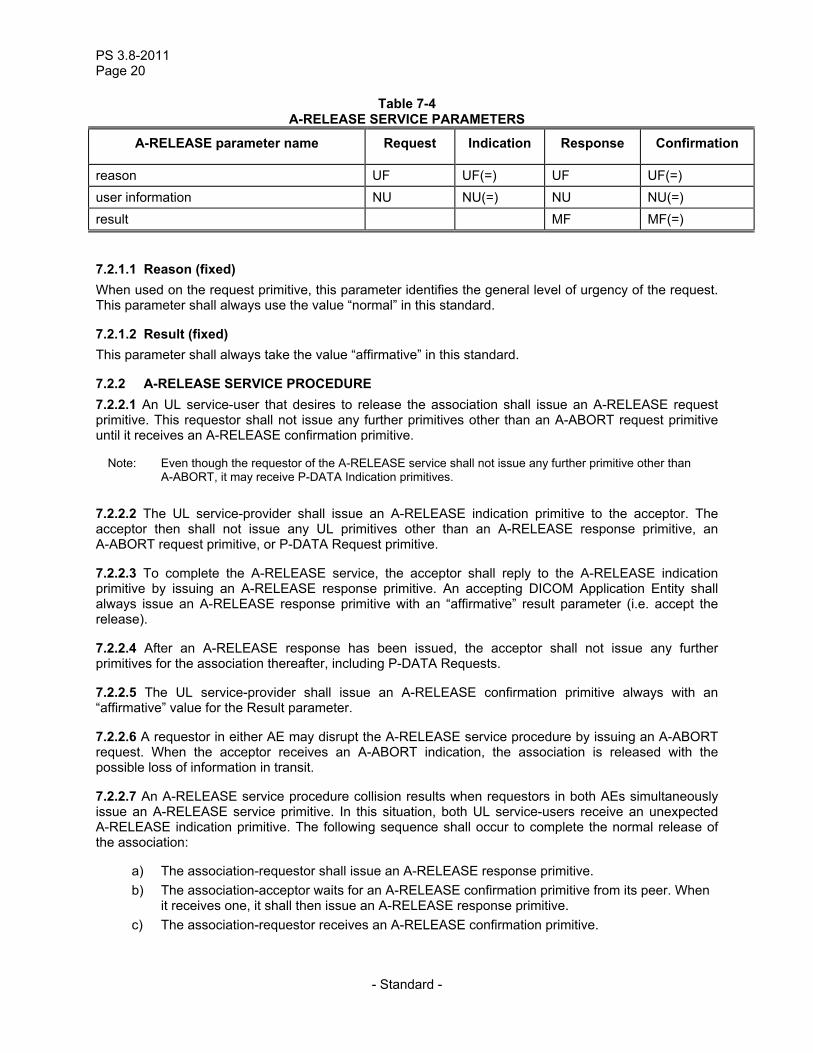
The ACSE A-P-ABORT service shall be used by the UL service-provider to signal the abnormal release of the association due to problems in services at the Presentation Layer and below. This occurrence indicates the possible loss of information in transit. A-P-ABORT is a provider-initiated service.
Figure 7-4 illustrates aborting an established association by an UL service-provider.
DICOM UL
Service Provider
(SAP) (SAP)
A-P-ABORT indication
A-P-ABORT indication
Figure 7-4 PROVIDER INITIATED ABORT
7.4.1 A-P-ABORT PARAMETER Table 7-6 lists the parameter which shall be required for the A-P-ABORT service.
Table 7-6 A-P-ABORT SERVICE PARAMETERS
A-P-ABORT Parameter Name Indication provider reason P
The provider reason parameter shall be used to convey one of the following reasons:
a) reason-not-specified b) unrecognized-pdu c) unexpected-pdu d) unexpected-session-service primitive e) unrecognized-pdu parameter
PS 3.8-2009 Page 23
- Standard -
f) unexpected-pdu parameter g) invalid-pdu-parameter value
Note: In addition to these reasons, a locally defined list of reasons may be used to reflect errors that caused the abort and originated in the Session, Transport, Network, Data Link, and Physical layers. The generation and handling of such errors is internal to an implementation and, therefore, is outside the scope of this communications standard.
7.4.2 A-P-ABORT SERVICE PROCEDURE When the UL service-provider detects an internal error, A-P-ABORT indication primitives shall be issued to acceptors in both AEs. The association shall be abnormally released. Requestors in both AEs shall not issue any further primitives for the association.
7.5 SEQUENCING INFORMATION
Interactions among the specific service procedures, discussed in Sections 7.1 through 7.4 for the ACSE subset of the Upper Layer Service, are defined in clause 10 of ISO 8649 - The ACSE Service Definition.
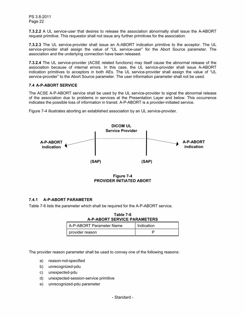
7.6 P-DATA SERVICE
This Presentation P-DATA Service shall be used by either AE to cause the exchange of application information (i.e. DICOM Messages). DICOM Messages shall be exchanged as defined in PS 3.7. An association provides a simultaneous bi-directional exchange of P-DATA request/indication primitives.
Figure 7-5 illustrates the transfer of data on an established association between two AEs.
DICOM UL
Service Provider
(SAP) (SAP)
P-DATA request
P-DATA indication
Figure 7-5 DATA TRANSFER
7.6.1 P-DATA PARAMETERS Table 7-7 lists the parameter which shall be required for the P-DATA service.
Table 7-7 P-DATA SERVICE PARAMETER
P-DATA Paramater Name Request Indication presentation data value list M M(=)
The Presentation Data Value List parameter shall contain one or more Presentation Data Values (PDV). Each PDV shall consist of two parameters: a Presentation Context ID and User Data values. The User Data values are taken from the Abstract Syntax and encoded in the Transfer Syntax identified by the Presentation Context ID. This referenced Presentation Context ID identifies one of the presentation
PS 3.8-2011 Page 24
- Standard -
contexts agreed to at association time. The User Data values format used in each PDV by the DICOM Application Entities is specified in Annex E.
8 Retired
9 DICOM upper layer protocol for TCP/IP
The DICOM Upper Layer Protocol specified in this section shall be used in conjunction with the TCP/IP transport layers..
9.1 USE OF THE TRANSPORT SERVICE PROVIDED BY TCP
9.1.1 GENERAL There is a one-to-one relationship between a TCP Transport Connection and an Upper Layer Association. Therefore, the following rules apply:
a) Each Upper Layer Association shall be supported by one and only one TCP Transport Connection.
b) Each TCP Transport Connection shall support one and only one Upper Layer Association.
The Services provided by the TCP Transport Services are not formally documented. This section, therefore, makes use of “commonly” used terms in a number of TCP Programming Interface Implementations (e.g. Sockets). However, the following RFCs shall be required for TCP/IP support. They specify the support needed for IPv4.
a) RFC 793, Transmission Control Program - DARPA Internet Protocol Specification b) RFC 791, Internet Protocol - DARPA Internet Protocol Specification c) RFC 792, Internet Control Message Protocol - DARPA Internet Program Protocol Specification d) RFC 950, Internet Subnetting
In addition, devices that support IPv6 shall comply with:
a) RFC 1881, IPv6 Address Allocation Management b) RFC 2460, Internet Protocol, Version 6 (IPv6) Specification
Note: There are many other RFC’s that may also apply to a particular implementation depending upon specific selections of hardware and software features.
For the establishment of a TCP connection, a TCP port shall be used to serve as the transport selector. A DICOM UL entity is identified on a given system on the network by a port number unique within the scope of this system. Port numbers of remote DICOM UL entities (well known port number or other numbers) shall be configurable on DICOM UL entities.
Note: It is strongly recommended that systems supporting a single DICOM UL entity use as their port the “well known port” registered for the DICOM Upper Layer Protocol: port number 104 (decimal), if the operating
PS 3.8-2009 Page 25
- Standard -
system permits access to privileged ports (in the range 0 to 1023), otherwise it is recommended that they use the “registered” port number 11112 (decimal). See “http://www.iana.org/assignments/port-numbers”.
Application Entities may also choose to access the TCP Transport Services via a Secure Transport Connection. The nature of this Secure Transport Connection is specified through Security Profiles (see PS 3.15). Security Profiles select minimum mechanisms needed to support that profile. Other mechanisms may also be used if agreed to during establishment of the Secure Transport Connection.
Notes: 1. DICOM does not specify how a secure transport connection is established, or the significance of any certificates exchanged during peer entity authentication. These issues are left up to the application, which is assumed to be following some security policy. Once the application has established a secure Transport Connection, then an Upper Layer Association can use that secure channel.
2. There may be an interaction between PDU size and record size of the secure Transport Connection that impacts efficiency of transport.
3. Registered ports for Secure Transport Connections are defined in PS3.15.
9.1.2 OPENING A TCP TRANSPORT CONNECTION When an Association is to be established by a DICOM Upper Layer Entity, a TRANSPORT CONNECT request primitive shall be issued to the TCP Transport Service (Active Open). Once the TCP Transport Connection Confirmation is received (Open Completed), an A-ASSOCIATE-RQ PDU shall be sent/written on the now established transport connection.
When a DICOM Upper Layer Entity becomes activated (Association Idle State), it shall wait for TCP Transport Connections in a passive mode by initiating a “listen.” When an incoming TCP Transport Connection Indication is received from the network, it is accepted and a timer ARTIM (Association Request/Reject/Release Timer) shall be set. Any further exchange of PDUs (read/write) shall be performed as specified by the Upper Layer State Machine (including ARTIM Timer expiration before an A-ASSOCIATE-RQ PDU is received, see Section 9.2).
9.1.3 TRANSFERRING DATA ON A TCP CONNECTION Data exchange of PDUs (read/write) on an established TCP Connection shall follow the specifications of the DICOM Upper Layer Protocol State Machine (see Section 9.2) and the DICOM Upper Layer PDU structure (see Section 9.3).
9.1.4 CLOSING A TCP TRANSPORT CONNECTION TCP Transport Connections shall be closed using the “don't linger” option.
A TCP Transport Connection is closed under a number of situations. These are described in the DICOM Upper Layer Protocol State Machine. Some typical cases are discussed below:
a) After an A-RELEASE-RQ has been sent and the A-RELEASE-RP PDU is received b) When a Transport Connection has been established by the DICOM remote UL Entity and no
A-ASSOCIATE-RQ is received before the ARTIM Timer expires c) When an A-ABORT PDU has been received d) When an A-ABORT PDU has been sent and the ARTIM Timer expires before the Transport
Connection is closed e) When a TCP connection is being disconnected by the Transport Service Provider (e.g.
network failure) f) When a TCP connection is being disconnected by the remote DICOM UL Entity
Notes 1. Except following the normal completion of an association reject, release or abort and in specific situations such as temporary lack of resources, an Upper Layer State Machine should not disconnect a TCP connection or reject its establishment. The appropriate behavior is to use the Association Reject or Abort services.
PS 3.8-2011 Page 26
- Standard -
2. The ARTIM Timer should not be used to oversee the Association Establishment or Release. Such a mechanism falls under the protocol definition of the layer above the DICOM Upper Layer (i.e. DICOM Application Entity, see PS 3.7).
9.1.5 ARTIM TIMER The value of the ARTIM Timer used to manage the Request, Reject, and Release of associations on a DICOM UL entity shall be configurable to address a wide range of network configurations.
9.2 DICOM UPPER LAYER PROTOCOL FOR TCP/IP STATE MACHINE
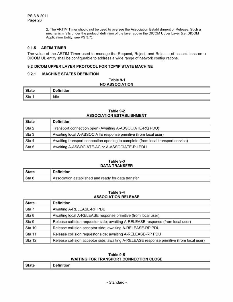
9.2.1 MACHINE STATES DEFINITION Table 9-1
NO ASSOCIATION State Definition Sta 1 Idle
Table 9-2 ASSOCIATION ESTABLISHMENT
State Definition Sta 2 Transport connection open (Awaiting A-ASSOCIATE-RQ PDU) Sta 3 Awaiting local A-ASSOCIATE response primitive (from local user) Sta 4 Awaiting transport connection opening to complete (from local transport service) Sta 5 Awaiting A-ASSOCIATE-AC or A-ASSOCIATE-RJ PDU
Table 9-3 DATA TRANSFER
State Definition Sta 6 Association established and ready for data transfer
Table 9-4 ASSOCIATION RELEASE
State Definition Sta 7 Awaiting A-RELEASE-RP PDU Sta 8 Awaiting local A-RELEASE response primitive (from local user) Sta 9 Release collision requestor side; awaiting A-RELEASE response (from local user) Sta 10 Release collision acceptor side; awaiting A-RELEASE-RP PDU Sta 11 Release collision requestor side; awaiting A-RELEASE-RP PDU Sta 12 Release collision acceptor side; awaiting A-RELEASE response primitive (from local user)
Table 9-5 WAITING FOR TRANSPORT CONNECTION CLOSE
State Definition
PS 3.8-2009 Page 27
- Standard -
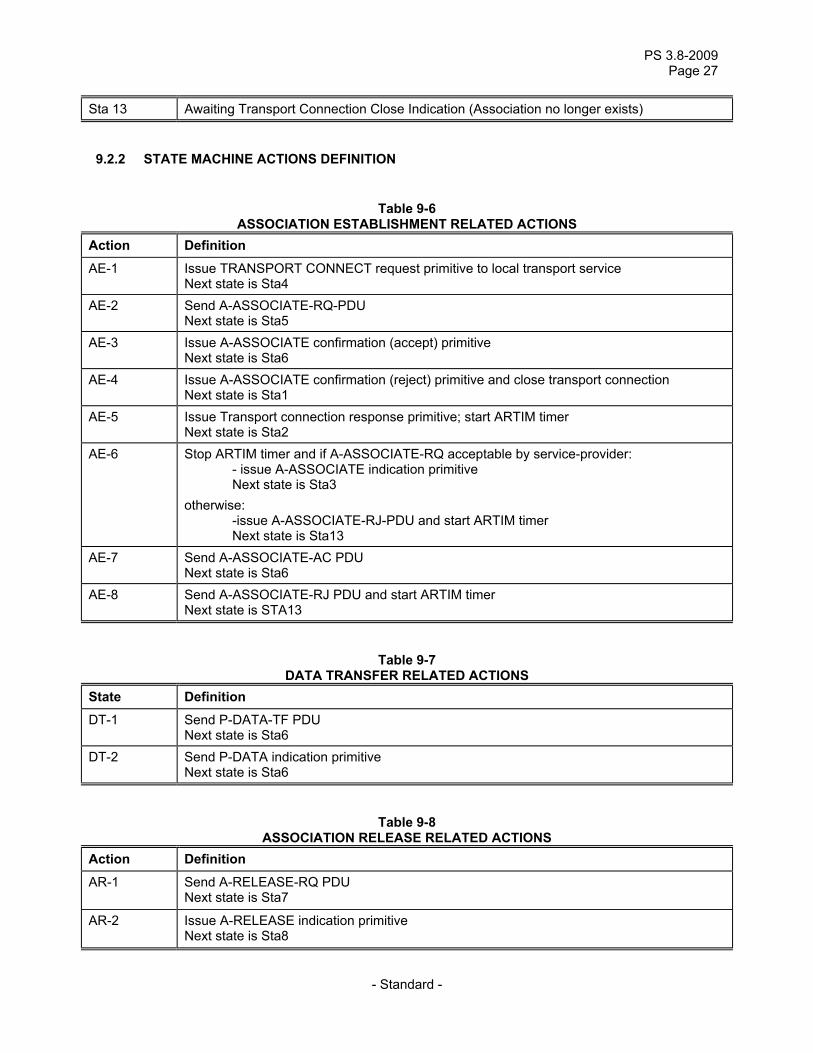
Sta 13 Awaiting Transport Connection Close Indication (Association no longer exists)
9.2.2 STATE MACHINE ACTIONS DEFINITION
Table 9-6 ASSOCIATION ESTABLISHMENT RELATED ACTIONS
Action Definition AE-1 Issue TRANSPORT CONNECT request primitive to local transport service
Next state is Sta4 AE-2 Send A-ASSOCIATE-RQ-PDU
Next state is Sta5 AE-3 Issue A-ASSOCIATE confirmation (accept) primitive
Next state is Sta6 AE-4 Issue A-ASSOCIATE confirmation (reject) primitive and close transport connection
Next state is Sta1 AE-5 Issue Transport connection response primitive; start ARTIM timer
Next state is Sta2 AE-6 Stop ARTIM timer and if A-ASSOCIATE-RQ acceptable by service-provider:
- issue A-ASSOCIATE indication primitive Next state is Sta3 otherwise: -issue A-ASSOCIATE-RJ-PDU and start ARTIM timer Next state is Sta13
AE-7 Send A-ASSOCIATE-AC PDU Next state is Sta6
AE-8 Send A-ASSOCIATE-RJ PDU and start ARTIM timer Next state is STA13
Table 9-7 DATA TRANSFER RELATED ACTIONS
State Definition DT-1 Send P-DATA-TF PDU
Next state is Sta6 DT-2 Send P-DATA indication primitive
Next state is Sta6
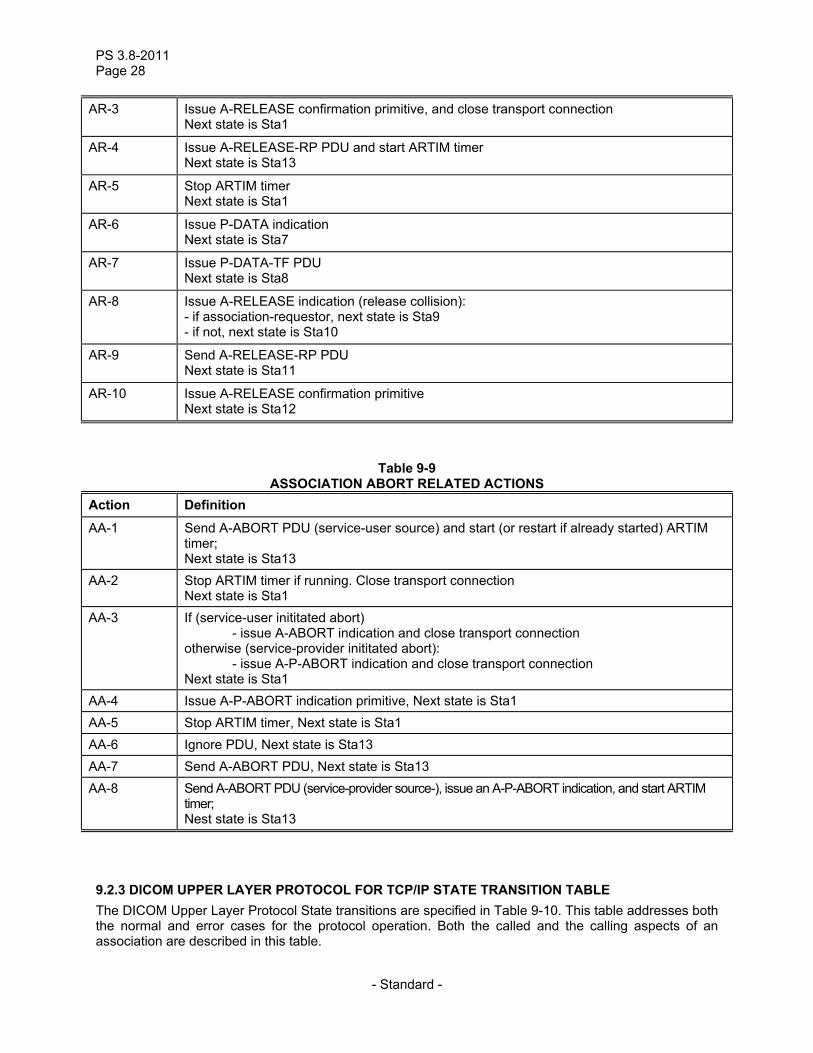
Table 9-8 ASSOCIATION RELEASE RELATED ACTIONS
Action Definition AR-1 Send A-RELEASE-RQ PDU
Next state is Sta7
AR-2 Issue A-RELEASE indication primitive Next state is Sta8
PS 3.8-2011 Page 28
- Standard -
AR-3 Issue A-RELEASE confirmation primitive, and close transport connection Next state is Sta1
AR-4 Issue A-RELEASE-RP PDU and start ARTIM timer Next state is Sta13
AR-5 Stop ARTIM timer Next state is Sta1
AR-6 Issue P-DATA indication Next state is Sta7
AR-7 Issue P-DATA-TF PDU Next state is Sta8
AR-8 Issue A-RELEASE indication (release collision): - if association-requestor, next state is Sta9 - if not, next state is Sta10
AR-9 Send A-RELEASE-RP PDU Next state is Sta11
AR-10 Issue A-RELEASE confirmation primitive Next state is Sta12
Table 9-9 ASSOCIATION ABORT RELATED ACTIONS
Action Definition AA-1 Send A-ABORT PDU (service-user source) and start (or restart if already started) ARTIM
timer; Next state is Sta13
AA-2 Stop ARTIM timer if running. Close transport connection Next state is Sta1
AA-3 If (service-user inititated abort) - issue A-ABORT indication and close transport connection otherwise (service-provider inititated abort): - issue A-P-ABORT indication and close transport connection Next state is Sta1
AA-4 Issue A-P-ABORT indication primitive, Next state is Sta1 AA-5 Stop ARTIM timer, Next state is Sta1 AA-6 Ignore PDU, Next state is Sta13 AA-7 Send A-ABORT PDU, Next state is Sta13 AA-8 Send A-ABORT PDU (service-provider source-), issue an A-P-ABORT indication, and start ARTIM
timer; Nest state is Sta13
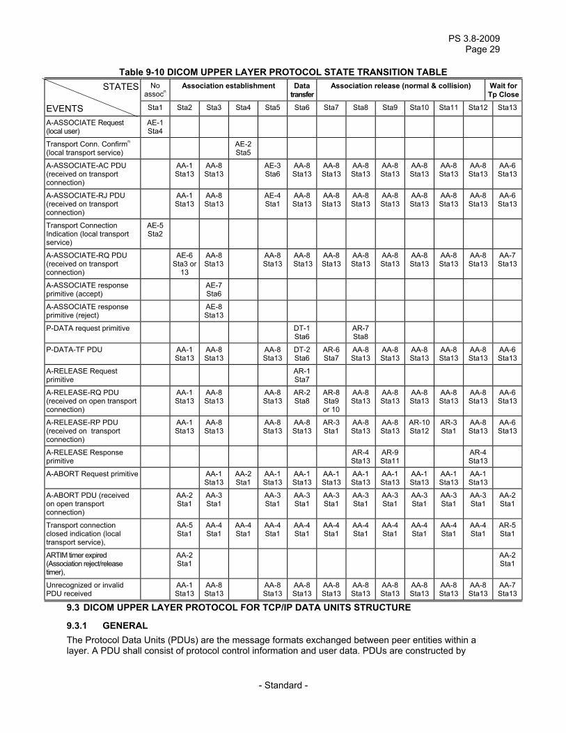
9.2.3 DICOM UPPER LAYER PROTOCOL FOR TCP/IP STATE TRANSITION TABLE The DICOM Upper Layer Protocol State transitions are specified in Table 9-10. This table addresses both the normal and error cases for the protocol operation. Both the called and the calling aspects of an association are described in this table.
PS 3.8-2009 Page 29
- Standard -
Table 9-10 DICOM UPPER LAYER PROTOCOL STATE TRANSITION TABLE STATES No
assocn Association establishment Data
transferAssociation release (normal & collision) Wait for
Tp Close
EVENTS Sta1 Sta2 Sta3 Sta4 Sta5 Sta6 Sta7 Sta8 Sta9 Sta10 Sta11 Sta12 Sta13
A-ASSOCIATE Request (local user)
AE-1 Sta4
Transport Conn. Confirmn (local transport service)
AE-2Sta5
A-ASSOCIATE-AC PDU (received on transport connection)
AA-1 Sta13
AA-8 Sta13
AE-3Sta6
AA-8Sta13
AA-8Sta13
AA-8Sta13
AA-8 Sta13
AA-8 Sta13
AA-8Sta13
AA-8Sta13
AA-6Sta13
A-ASSOCIATE-RJ PDU (received on transport connection)
AA-1 Sta13
AA-8 Sta13
AE-4Sta1
AA-8Sta13
AA-8Sta13
AA-8Sta13
AA-8 Sta13
AA-8 Sta13
AA-8Sta13
AA-8Sta13
AA-6Sta13
Transport Connection Indication (local transport service)
AE-5 Sta2
A-ASSOCIATE-RQ PDU (received on transport connection)
AE-6 Sta3 or
13
AA-8 Sta13
AA-8Sta13
AA-8 Sta13
AA-8Sta13
AA-8Sta13
AA-8 Sta13
AA-8 Sta13
AA-8Sta13
AA-8Sta13
AA-7Sta13
A-ASSOCIATE response primitive (accept)
AE-7 Sta6
A-ASSOCIATE response primitive (reject)
AE-8 Sta13
P-DATA request primitive DT-1Sta6
AR-7Sta8
P-DATA-TF PDU AA-1 Sta13
AA-8 Sta13
AA-8Sta13
DT-2Sta6
AR-6Sta7
AA-8Sta13
AA-8 Sta13
AA-8 Sta13
AA-8Sta13
AA-8Sta13
AA-6Sta13
A-RELEASE Request primitive
AR-1Sta7
A-RELEASE-RQ PDU (received on open transport connection)
AA-1 Sta13
AA-8 Sta13
AA-8Sta13
AR-2Sta8
AR-8 Sta9or 10
AA-8Sta13
AA-8 Sta13
AA-8 Sta13
AA-8Sta13
AA-8Sta13
AA-6Sta13
A-RELEASE-RP PDU (received on transport connection)
AA-1 Sta13
AA-8 Sta13
AA-8Sta13
AA-8Sta13
AR-3Sta1
AA-8Sta13
AA-8 Sta13
AR-10 Sta12
AR-3Sta1
AA-8Sta13
AA-6Sta13
A-RELEASE Response primitive
AR-4Sta13
AR-9 Sta11
AR-4Sta13
A-ABORT Request primitive AA-1 Sta13
AA-2Sta1
AA-1Sta13
AA-1Sta13
AA-1Sta13
AA-1Sta13
AA-1 Sta13
AA-1 Sta13
AA-1Sta13
AA-1Sta13
A-ABORT PDU (received on open transport connection)
AA-2 Sta1
AA-3 Sta1
AA-3Sta1
AA-3Sta1
AA-3Sta1
AA-3Sta1
AA-3 Sta1
AA-3 Sta1
AA-3Sta1
AA-3Sta1
AA-2Sta1
Transport connection closed indication (local transport service),
AA-5 Sta1
AA-4 Sta1
AA-4Sta1
AA-4Sta1
AA-4Sta1
AA-4Sta1
AA-4Sta1
AA-4 Sta1
AA-4 Sta1
AA-4Sta1
AA-4Sta1
AR-5Sta1
ARTIM timer expired (Association reject/release timer),
AA-2 Sta1
AA-2Sta1
Unrecognized or invalid PDU received
AA-1 Sta13
AA-8 Sta13
AA-8Sta13
AA-8Sta13
AA-8Sta13
AA-8Sta13
AA-8 Sta13
AA-8 Sta13
AA-8Sta13
AA-8Sta13
AA-7Sta13
9.3 DICOM UPPER LAYER PROTOCOL FOR TCP/IP DATA UNITS STRUCTURE
9.3.1 GENERAL The Protocol Data Units (PDUs) are the message formats exchanged between peer entities within a layer. A PDU shall consist of protocol control information and user data. PDUs are constructed by
PS 3.8-2011 Page 30
- Standard -
mandatory fixed fields followed by optional variable fields which contain one or more items and/or sub-items.
Items of unrecognized types shall be ignored and skipped. Items shall appear in an increasing order of their item types. Several instances of the same item shall be acceptable or shall not as specified by each item.
The DICOM UL protocol consists of seven Protocol Data Units:
a) A-ASSOCIATE-RQ PDU b) A-ASSOCIATE-AC PDU c) A-ASSOCIATE-RJ PDU d) P-DATA-TF PDU e) A-RELEASE-RQ PDU f) A-RELEASE-RP PDU g) A-ABORT PDU
The encoding of the DICOM UL PDUs is defined as follows (Big Endian byte ordering):
Note: The Big Endian byte ordering has been chosen for consistency with the OSI and TCP/IP environment. This pertains to the DICOM UL PDU headers only. The encoding of the PDV message fragments is defined by the Transfer Syntax negotiated at association establishment.
a) Each PDU type shall consist of one or more bytes that when represented, are numbered
sequentially, with byte 1 being the lowest byte number. b) Each byte within the PDU shall consist of eight bits that, when represented, are numbered 7 to
0, where bit 0 is the low order bit. c) When consecutive bytes are used to represent a string of characters, the lowest byte numbers
represent the first character. d) When consecutive bytes are used to represent a binary number, the lower byte number has
the most significant value. e) The lowest byte number is placed first in the transport service data flow. f) An overview of the PDUs is shown in Figures 9-1 and 9-2. The detailed structure of each PDU
is specified in the following sections. Note: A number of parameters defined in the UL Service are not reflected in these PDUs (e.g. service
parameters, fixed values, values not used by DICOM Application Entities.)
PS 3.8-2009 Page 31
- Standard -
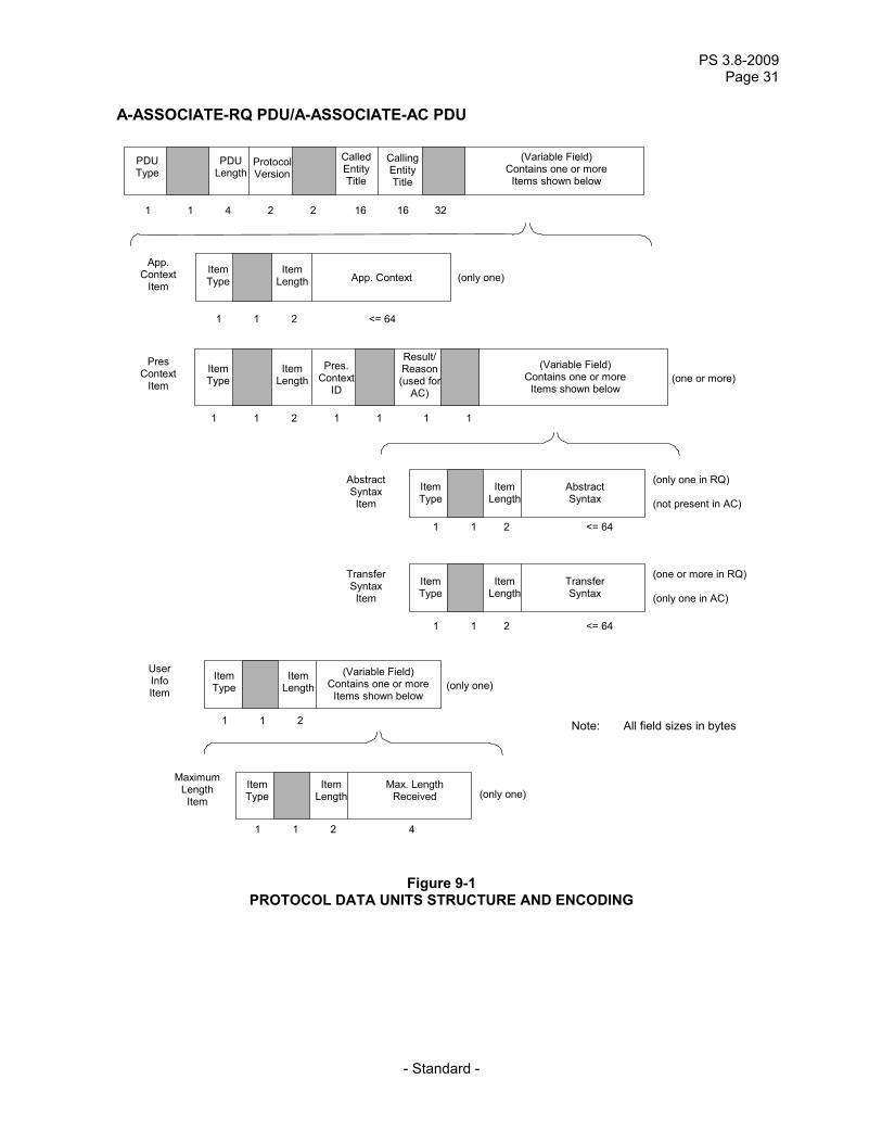
A-ASSOCIATE-RQ PDU/A-ASSOCIATE-AC PDU
PDU Type
PDU Length
Protocol Version
Called Entity Title
CallingEntity Title
(Variable Field) Contains one or more
Items shown below
1 1 4 2 2 16 16 32
1 1 2 <= 64
App. Context
Item Item Type
Item Length
App. Context
(only one)
Pres Context
Item Item Type
Item Length
Pres. Context
ID
Result/Reason(used for
AC)
(Variable Field) Contains one or more
Items shown below
1 1 2 1 1 1 1
(one or more)
Abstract Syntax Item
1 1 2 <= 64
Item Type
Item Length
AbstractSyntax
(only one in RQ) (not present in AC)
Transfer Syntax Item
1 1 2 <= 64
Item Type
Item Length
TransferSyntax
(one or more in RQ) (only one in AC)
1 1 2
Item Type
Item Length
(Variable Field) Contains one or more
Items shown below
(only one)
User Info Item
1 1 2 4
(only one)
Item Type
Item Length
Max. Length Received
Maximum Length Item
Note: All field sizes in bytes
Figure 9-1 PROTOCOL DATA UNITS STRUCTURE AND ENCODING
PS 3.8-2011 Page 32
- Standard -
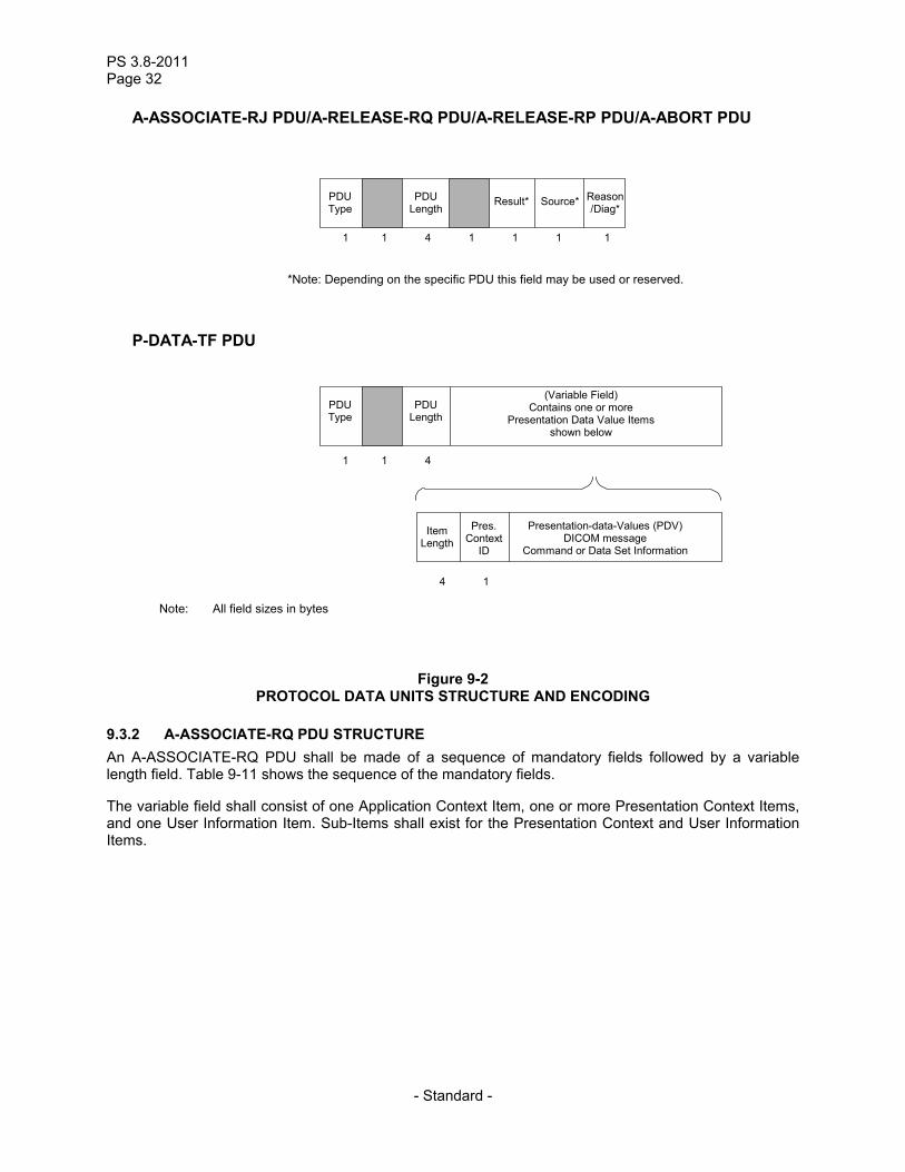
A-ASSOCIATE-RJ PDU/A-RELEASE-RQ PDU/A-RELEASE-RP PDU/A-ABORT PDU
Note: All field sizes in bytes
1 1 4
PDU Type
PDU Length
Result* Source* Reason/Diag*
1 1 1 1
P-DATA-TF PDU
*Note: Depending on the specific PDU this field may be used or reserved.
(Variable Field) Contains one or more
Presentation Data Value Items shown below
1 1 4
PDU Type
PDU Length
Pres. Context
ID
Presentation-data-Values (PDV) DICOM message
Command or Data Set Information
4 1
Item Length
Figure 9-2 PROTOCOL DATA UNITS STRUCTURE AND ENCODING
9.3.2 A-ASSOCIATE-RQ PDU STRUCTURE An A-ASSOCIATE-RQ PDU shall be made of a sequence of mandatory fields followed by a variable length field. Table 9-11 shows the sequence of the mandatory fields.
The variable field shall consist of one Application Context Item, one or more Presentation Context Items, and one User Information Item. Sub-Items shall exist for the Presentation Context and User Information Items.

PS 3.8-2009 Page 33
- Standard -
Table 9-11 ASSOCIATE-RQ PDU fields
PDU bytes Field name Description of field
1 PDU-type 01H 2 Reserved This reserved field shall be sent with a value 00H but not tested to this
value when received. 3-6 PDU-length This PDU-length shall be the number of bytes from the first byte of the
following field to the last byte of the variable field. It shall be encoded as an unsigned binary number
7-8 Protocol-version This two byte field shall use one bit to identify each version of the DICOM UL protocol supported by the calling end-system. This is Version 1 and shall be identified with bit 0 set. A receiver of this PDU implementing only this version of the DICOM UL protocol shall only test that bit 0 is set.
9-10 Reserved This reserved field shall be sent with a value 0000H but not tested to this value when received.
11-26 Called-AE-title Destination DICOM Application Name. It shall be encoded as 16 characters as defined by the ISO 646:1990-Basic G0 Set with leading and trailing spaces (20H) being non-significant. The value made of 16 spaces (20H) meaning “no Application Name specified” shall not be used. For a complete description of the use of this field, see Section 7.1.1.4.
27-42 Calling-AE-title Source DICOM Application Name. It shall be encoded as 16 characters as defined by the ISO 646:1990-Basic G0 Set with leading and trailing spaces (20H) being non-significant. The value made of 16 spaces (20H) meaning “no Application Name specified” shall not be used. For a complete description of the use of this field, see Section 7.1.1.3.
43-74 Reserved This reserved field shall be sent with a value 00H for all bytes but not tested to this value when received
75-xxx Variable items This variable field shall contain the following items: one Application Context Item, one or more Presentation Context Items and one User Information Item. For a complete description of the use of these items see Sections 7.1.1.2, 7.1.1.13, and 7.1.1.6.
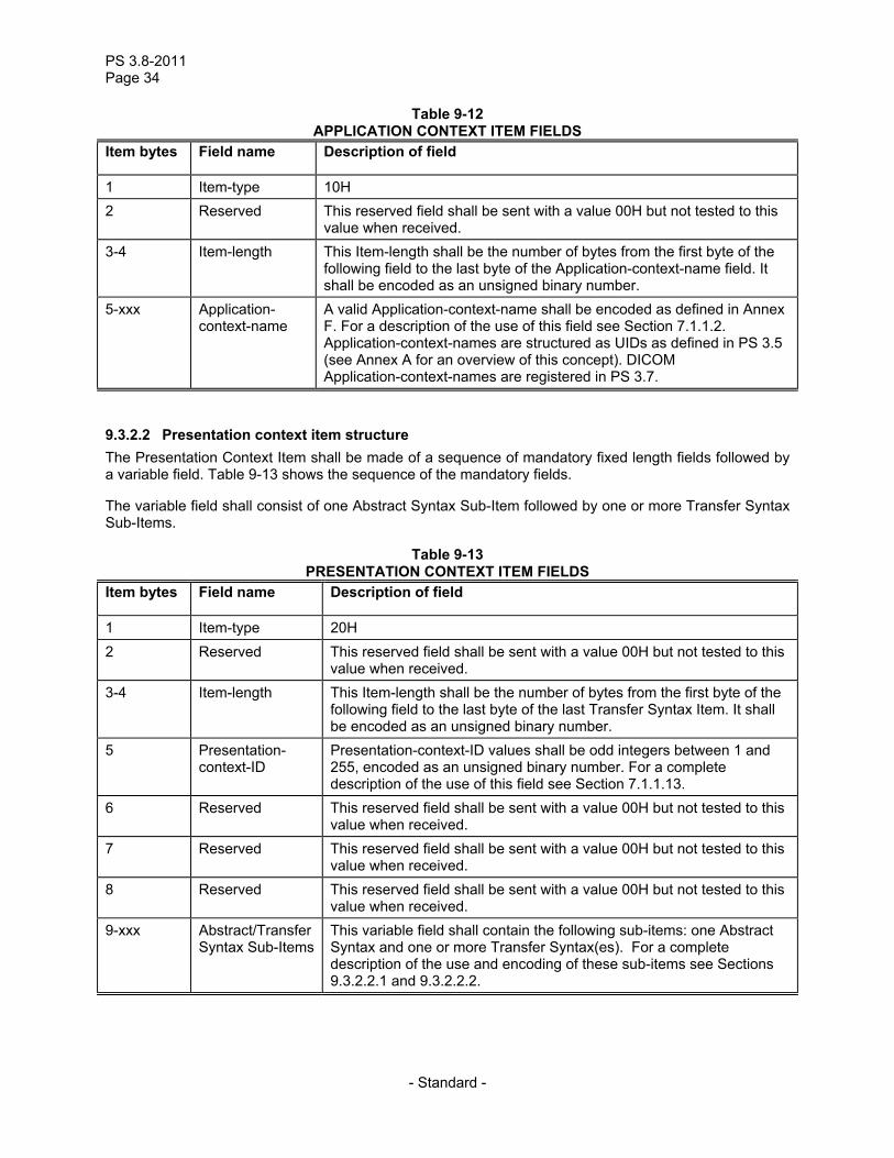
9.3.2.1 Application context item structure An Application Context Item shall be made of a sequence of mandatory fields followed by a variable length field. Table 9-12 shows the sequence of the mandatory fields.
PS 3.8-2011 Page 34
- Standard -
Table 9-12 APPLICATION CONTEXT ITEM FIELDS
Item bytes Field name Description of field
1 Item-type 10H 2 Reserved This reserved field shall be sent with a value 00H but not tested to this
value when received. 3-4 Item-length This Item-length shall be the number of bytes from the first byte of the
following field to the last byte of the Application-context-name field. It shall be encoded as an unsigned binary number.
5-xxx Application-context-name
A valid Application-context-name shall be encoded as defined in Annex F. For a description of the use of this field see Section 7.1.1.2. Application-context-names are structured as UIDs as defined in PS 3.5 (see Annex A for an overview of this concept). DICOM Application-context-names are registered in PS 3.7.
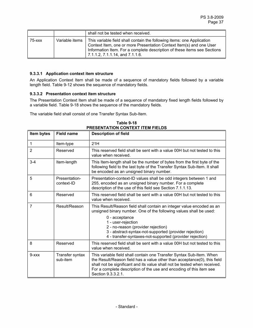
9.3.2.2 Presentation context item structure The Presentation Context Item shall be made of a sequence of mandatory fixed length fields followed by a variable field. Table 9-13 shows the sequence of the mandatory fields.
The variable field shall consist of one Abstract Syntax Sub-Item followed by one or more Transfer Syntax Sub-Items.
Table 9-13 PRESENTATION CONTEXT ITEM FIELDS
Item bytes Field name Description of field
1 Item-type 20H 2 Reserved This reserved field shall be sent with a value 00H but not tested to this
value when received. 3-4 Item-length This Item-length shall be the number of bytes from the first byte of the
following field to the last byte of the last Transfer Syntax Item. It shall be encoded as an unsigned binary number.
5 Presentation- context-ID
Presentation-context-ID values shall be odd integers between 1 and 255, encoded as an unsigned binary number. For a complete description of the use of this field see Section 7.1.1.13.
6 Reserved This reserved field shall be sent with a value 00H but not tested to this value when received.
7 Reserved This reserved field shall be sent with a value 00H but not tested to this value when received.
8 Reserved This reserved field shall be sent with a value 00H but not tested to this value when received.
9-xxx Abstract/Transfer Syntax Sub-Items
This variable field shall contain the following sub-items: one Abstract Syntax and one or more Transfer Syntax(es). For a complete description of the use and encoding of these sub-items see Sections 9.3.2.2.1 and 9.3.2.2.2.
PS 3.8-2009 Page 35
- Standard -
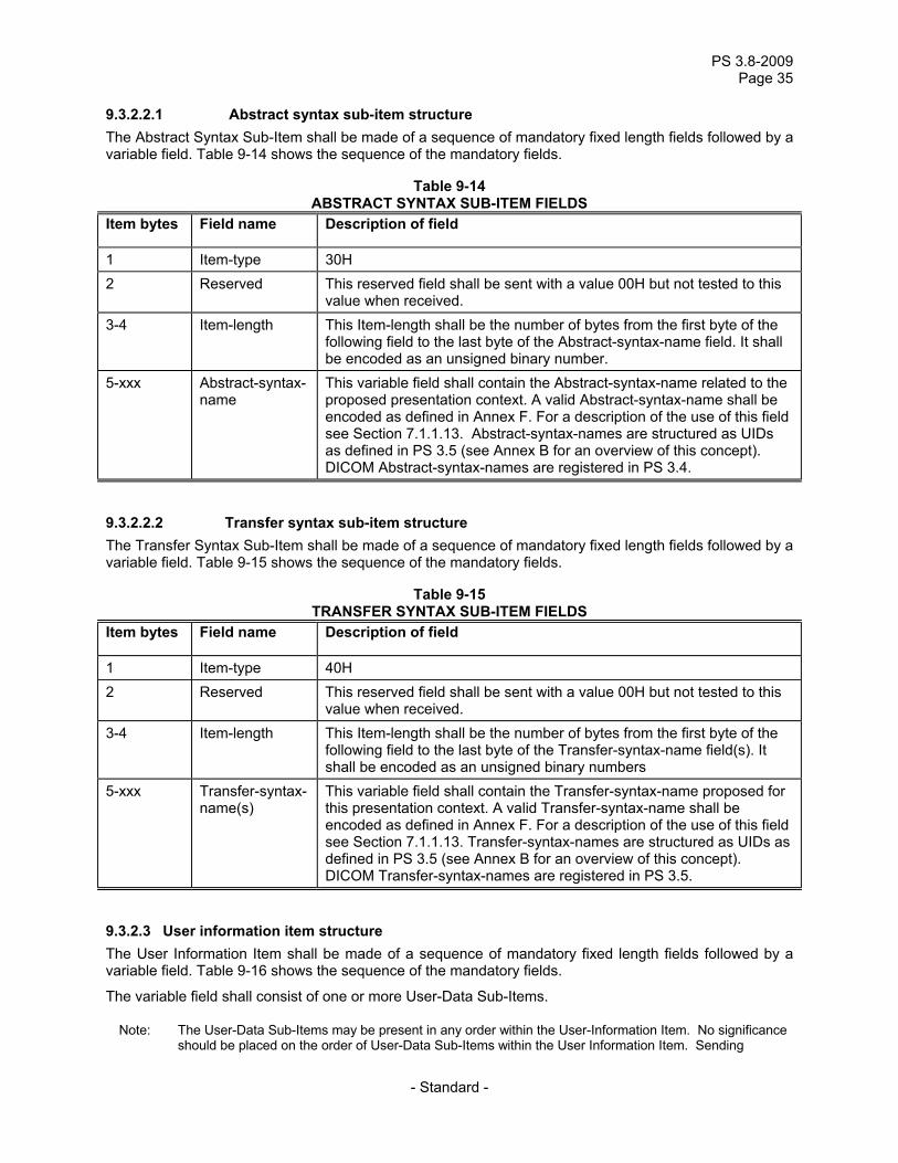
9.3.2.2.1 Abstract syntax sub-item structure The Abstract Syntax Sub-Item shall be made of a sequence of mandatory fixed length fields followed by a variable field. Table 9-14 shows the sequence of the mandatory fields.
Table 9-14 ABSTRACT SYNTAX SUB-ITEM FIELDS
Item bytes Field name Description of field
1 Item-type 30H 2 Reserved This reserved field shall be sent with a value 00H but not tested to this
value when received. 3-4 Item-length This Item-length shall be the number of bytes from the first byte of the
following field to the last byte of the Abstract-syntax-name field. It shall be encoded as an unsigned binary number.
5-xxx Abstract-syntax-name
This variable field shall contain the Abstract-syntax-name related to the proposed presentation context. A valid Abstract-syntax-name shall be encoded as defined in Annex F. For a description of the use of this field see Section 7.1.1.13. Abstract-syntax-names are structured as UIDs as defined in PS 3.5 (see Annex B for an overview of this concept). DICOM Abstract-syntax-names are registered in PS 3.4.
9.3.2.2.2 Transfer syntax sub-item structure The Transfer Syntax Sub-Item shall be made of a sequence of mandatory fixed length fields followed by a variable field. Table 9-15 shows the sequence of the mandatory fields.
Table 9-15 TRANSFER SYNTAX SUB-ITEM FIELDS
Item bytes Field name Description of field
1 Item-type 40H 2 Reserved This reserved field shall be sent with a value 00H but not tested to this
value when received. 3-4 Item-length This Item-length shall be the number of bytes from the first byte of the
following field to the last byte of the Transfer-syntax-name field(s). It shall be encoded as an unsigned binary numbers
5-xxx Transfer-syntax-name(s)
This variable field shall contain the Transfer-syntax-name proposed for this presentation context. A valid Transfer-syntax-name shall be encoded as defined in Annex F. For a description of the use of this field see Section 7.1.1.13. Transfer-syntax-names are structured as UIDs as defined in PS 3.5 (see Annex B for an overview of this concept). DICOM Transfer-syntax-names are registered in PS 3.5.
9.3.2.3 User information item structure The User Information Item shall be made of a sequence of mandatory fixed length fields followed by a variable field. Table 9-16 shows the sequence of the mandatory fields.
The variable field shall consist of one or more User-Data Sub-Items.
Note: The User-Data Sub-Items may be present in any order within the User-Information Item. No significance should be placed on the order of User-Data Sub-Items within the User Information Item. Sending
PS 3.8-2011 Page 36
- Standard -
applications should be aware that some older applications might expect Sub-Items to be encoded in ascending order of Item-type within the enclosing Item.
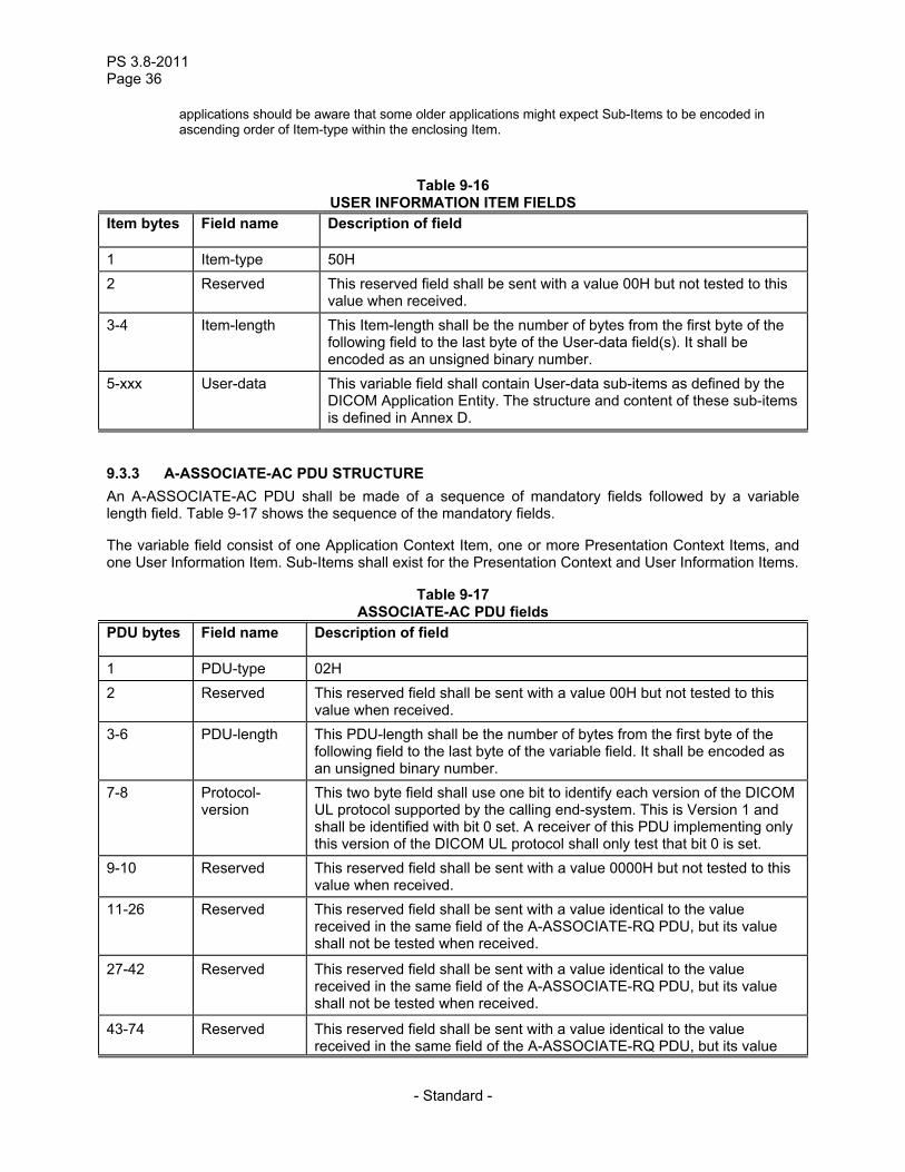
Table 9-16 USER INFORMATION ITEM FIELDS
Item bytes Field name Description of field
1 Item-type 50H 2 Reserved This reserved field shall be sent with a value 00H but not tested to this
value when received. 3-4 Item-length This Item-length shall be the number of bytes from the first byte of the
following field to the last byte of the User-data field(s). It shall be encoded as an unsigned binary number.
5-xxx User-data This variable field shall contain User-data sub-items as defined by the DICOM Application Entity. The structure and content of these sub-items is defined in Annex D.
9.3.3 A-ASSOCIATE-AC PDU STRUCTURE An A-ASSOCIATE-AC PDU shall be made of a sequence of mandatory fields followed by a variable length field. Table 9-17 shows the sequence of the mandatory fields.
The variable field consist of one Application Context Item, one or more Presentation Context Items, and one User Information Item. Sub-Items shall exist for the Presentation Context and User Information Items.
Table 9-17 ASSOCIATE-AC PDU fields
PDU bytes Field name Description of field
1 PDU-type 02H 2 Reserved This reserved field shall be sent with a value 00H but not tested to this
value when received. 3-6 PDU-length This PDU-length shall be the number of bytes from the first byte of the
following field to the last byte of the variable field. It shall be encoded as an unsigned binary number.
7-8 Protocol- version
This two byte field shall use one bit to identify each version of the DICOM UL protocol supported by the calling end-system. This is Version 1 and shall be identified with bit 0 set. A receiver of this PDU implementing only this version of the DICOM UL protocol shall only test that bit 0 is set.
9-10 Reserved This reserved field shall be sent with a value 0000H but not tested to this value when received.
11-26 Reserved This reserved field shall be sent with a value identical to the value received in the same field of the A-ASSOCIATE-RQ PDU, but its value shall not be tested when received.
27-42 Reserved This reserved field shall be sent with a value identical to the value received in the same field of the A-ASSOCIATE-RQ PDU, but its value shall not be tested when received.
43-74 Reserved This reserved field shall be sent with a value identical to the value received in the same field of the A-ASSOCIATE-RQ PDU, but its value
PS 3.8-2009 Page 37
- Standard -
shall not be tested when received.
75-xxx Variable items This variable field shall contain the following items: one Application Context Item, one or more Presentation Context Item(s) and one User Information Item. For a complete description of these items see Sections 7.1.1.2, 7.1.1.14, and 7.1.1.6.
9.3.3.1 Application context item structure An Application Context Item shall be made of a sequence of mandatory fields followed by a variable length field. Table 9-12 shows the sequence of mandatory fields.
9.3.3.2 Presentation context item structure The Presentation Context Item shall be made of a sequence of mandatory fixed length fields followed by a variable field. Table 9-18 shows the sequence of the mandatory fields.
The variable field shall consist of one Transfer Syntax Sub-Item.
Table 9-18 PRESENTATION CONTEXT ITEM FIELDS
Item bytes Field name Description of field
1 Item-type 21H 2 Reserved This reserved field shall be sent with a value 00H but not tested to this
value when received. 3-4 Item-length This Item-length shall be the number of bytes from the first byte of the
following field to the last byte of the Transfer Syntax Sub-Item. It shall be encoded as an unsigned binary number.
5 Presentation- context-ID
Presentation-context-ID values shall be odd integers between 1 and 255, encoded as an unsigned binary number. For a complete description of the use of this field see Section 7.1.1.13.
6 Reserved This reserved field shall be sent with a value 00H but not tested to this value when received.
7 Result/Reason This Result/Reason field shall contain an integer value encoded as an unsigned binary number. One of the following values shall be used: 0 - acceptance 1 - user-rejection 2 - no-reason (provider rejection) 3 - abstract-syntax-not-supported (provider rejection) 4 - transfer-syntaxes-not-supported (provider rejection)
8 Reserved This reserved field shall be sent with a value 00H but not tested to this value when received.
9-xxx Transfer syntax sub-item
This variable field shall contain one Transfer Syntax Sub-Item. When the Result/Reason field has a value other than acceptance(0), this field shall not be significant and its value shall not be tested when received. For a complete description of the use and encoding of this item see Section 9.3.3.2.1.
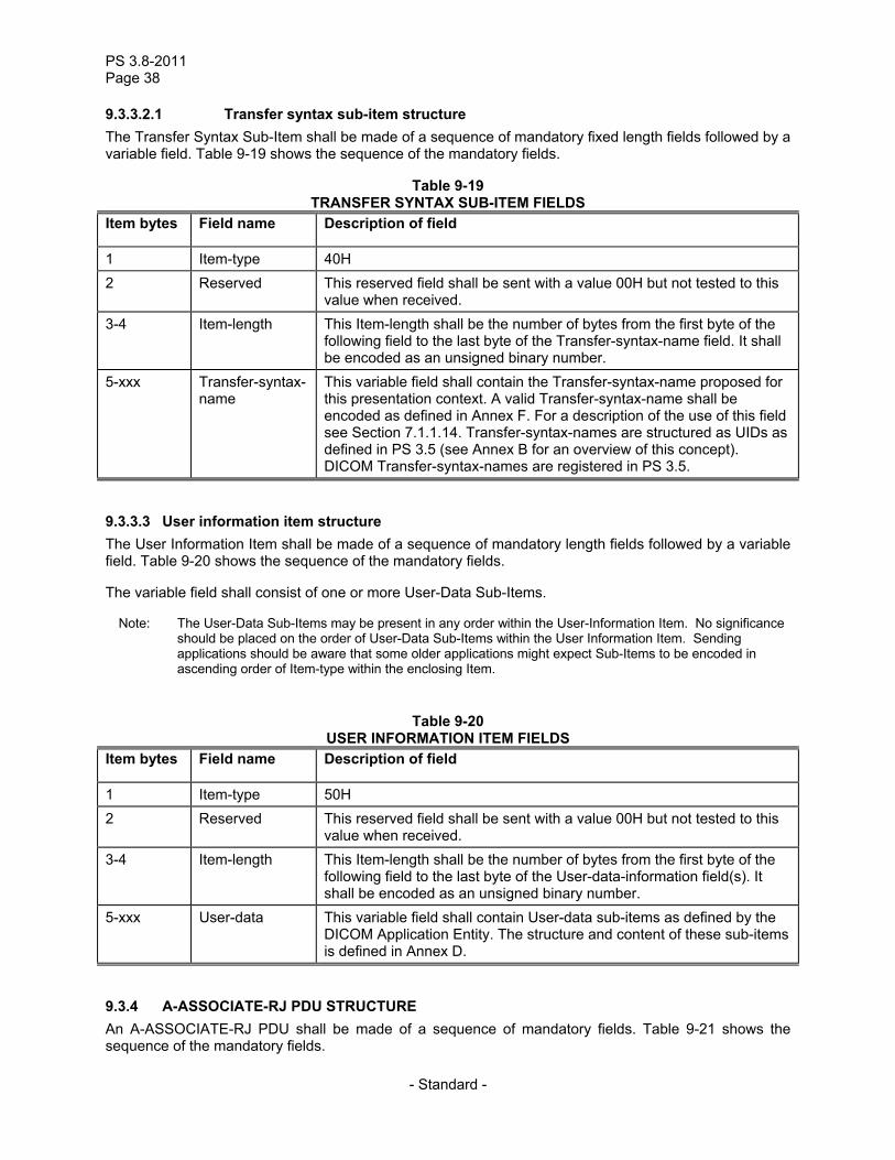
PS 3.8-2011 Page 38
- Standard -
9.3.3.2.1 Transfer syntax sub-item structure The Transfer Syntax Sub-Item shall be made of a sequence of mandatory fixed length fields followed by a variable field. Table 9-19 shows the sequence of the mandatory fields.
Table 9-19 TRANSFER SYNTAX SUB-ITEM FIELDS
Item bytes Field name Description of field
1 Item-type 40H 2 Reserved This reserved field shall be sent with a value 00H but not tested to this
value when received. 3-4 Item-length This Item-length shall be the number of bytes from the first byte of the
following field to the last byte of the Transfer-syntax-name field. It shall be encoded as an unsigned binary number.
5-xxx Transfer-syntax-name
This variable field shall contain the Transfer-syntax-name proposed for this presentation context. A valid Transfer-syntax-name shall be encoded as defined in Annex F. For a description of the use of this field see Section 7.1.1.14. Transfer-syntax-names are structured as UIDs as defined in PS 3.5 (see Annex B for an overview of this concept). DICOM Transfer-syntax-names are registered in PS 3.5.
9.3.3.3 User information item structure The User Information Item shall be made of a sequence of mandatory length fields followed by a variable field. Table 9-20 shows the sequence of the mandatory fields.
The variable field shall consist of one or more User-Data Sub-Items.
Note: The User-Data Sub-Items may be present in any order within the User-Information Item. No significance should be placed on the order of User-Data Sub-Items within the User Information Item. Sending applications should be aware that some older applications might expect Sub-Items to be encoded in ascending order of Item-type within the enclosing Item.
Table 9-20 USER INFORMATION ITEM FIELDS
Item bytes Field name Description of field
1 Item-type 50H 2 Reserved This reserved field shall be sent with a value 00H but not tested to this
value when received. 3-4 Item-length This Item-length shall be the number of bytes from the first byte of the
following field to the last byte of the User-data-information field(s). It shall be encoded as an unsigned binary number.
5-xxx User-data This variable field shall contain User-data sub-items as defined by the DICOM Application Entity. The structure and content of these sub-items is defined in Annex D.
9.3.4 A-ASSOCIATE-RJ PDU STRUCTURE An A-ASSOCIATE-RJ PDU shall be made of a sequence of mandatory fields. Table 9-21 shows the sequence of the mandatory fields.
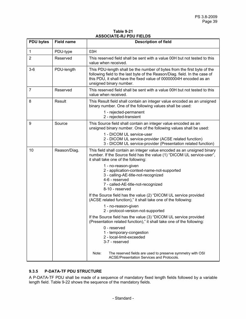
PS 3.8-2009 Page 39
- Standard -
Table 9-21 ASSOCIATE-RJ PDU FIELDS
PDU bytes Field name Description of field
1 PDU-type 03H 2 Reserved This reserved field shall be sent with a value 00H but not tested to this
value when received. 3-6 PDU-length This PDU-length shall be the number of bytes from the first byte of the
following field to the last byte of the Reason/Diag. field. In the case of this PDU, it shall have the fixed value of 00000004H encoded as an unsigned binary number.
7 Reserved This reserved field shall be sent with a value 00H but not tested to this value when received.
8 Result This Result field shall contain an integer value encoded as an unsigned binary number. One of the following values shall be used: 1 - rejected-permanent 2 - rejected-transient
9 Source This Source field shall contain an integer value encoded as an unsigned binary number. One of the following values shall be used: 1 - DICOM UL service-user 2 - DICOM UL service-provider (ACSE related function) 3 - DICOM UL service-provider (Presentation related function)
10 Reason/Diag. This field shall contain an integer value encoded as an unsigned binary number. If the Source field has the value (1) “DICOM UL service-user”, it shall take one of the following: 1 - no-reason-given 2 - application-context-name-not-supported 3 - calling-AE-title-not-recognized 4-6 - reserved 7 - called-AE-title-not-recognized 8-10 - reserved If the Source field has the value (2) “DICOM UL service provided (ACSE related function),” it shall take one of the following: 1 - no-reason-given 2 - protocol-version-not-supported If the Source field has the value (3) “DICOM UL service provided (Presentation related function),” it shall take one of the following: 0 - reserved 1 - temporary-congestion 2 - local-limit-exceeded 3-7 - reserved
Note: The reserved fields are used to preserve symmetry with OSI ACSE/Presentation Services and Protocols.
9.3.5 P-DATA-TF PDU STRUCTURE A P-DATA-TF PDU shall be made of a sequence of mandatory fixed length fields followed by a variable length field. Table 9-22 shows the sequence of the mandatory fields.
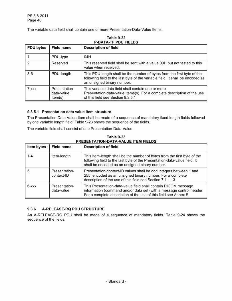
PS 3.8-2011 Page 40
- Standard -
The variable data field shall contain one or more Presentation-Data-Value Items.
Table 9-22 P-DATA-TF PDU FIELDS
PDU bytes Field name Description of field
1 PDU-type 04H 2 Reserved This reserved field shall be sent with a value 00H but not tested to this
value when received. 3-6 PDU-length This PDU-length shall be the number of bytes from the first byte of the
following field to the last byte of the variable field. It shall be encoded as an unsigned binary number.
7-xxx Presentation- data-value Item(s),
This variable data field shall contain one or more Presentation-data-value Items(s). For a complete description of the use of this field see Section 9.3.5.1
9.3.5.1 Presentation data value item structure The Presentation Data Value Item shall be made of a sequence of mandatory fixed length fields followed by one variable length field. Table 9-23 shows the sequence of the fields.
The variable field shall consist of one Presentation-Data-Value.
Table 9-23 PRESENTATION-DATA-VALUE ITEM FIELDS
Item bytes Field name Description of field
1-4 Item-length This Item-length shall be the number of bytes from the first byte of the following field to the last byte of the Presentation-data-value field. It shall be encoded as an unsigned binary number.
5 Presentation- context-ID
Presentation-context-ID values shall be odd integers between 1 and 255, encoded as an unsigned binary number. For a complete description of the use of this field see Section 7.1.1.13.
6-xxx Presentation- data-value
This Presentation-data-value field shall contain DICOM message information (command and/or data set) with a message control header. For a complete description of the use of this field see Annex E.
9.3.6 A-RELEASE-RQ PDU STRUCTURE An A-RELEASE-RQ PDU shall be made of a sequence of mandatory fields. Table 9-24 shows the sequence of the fields.
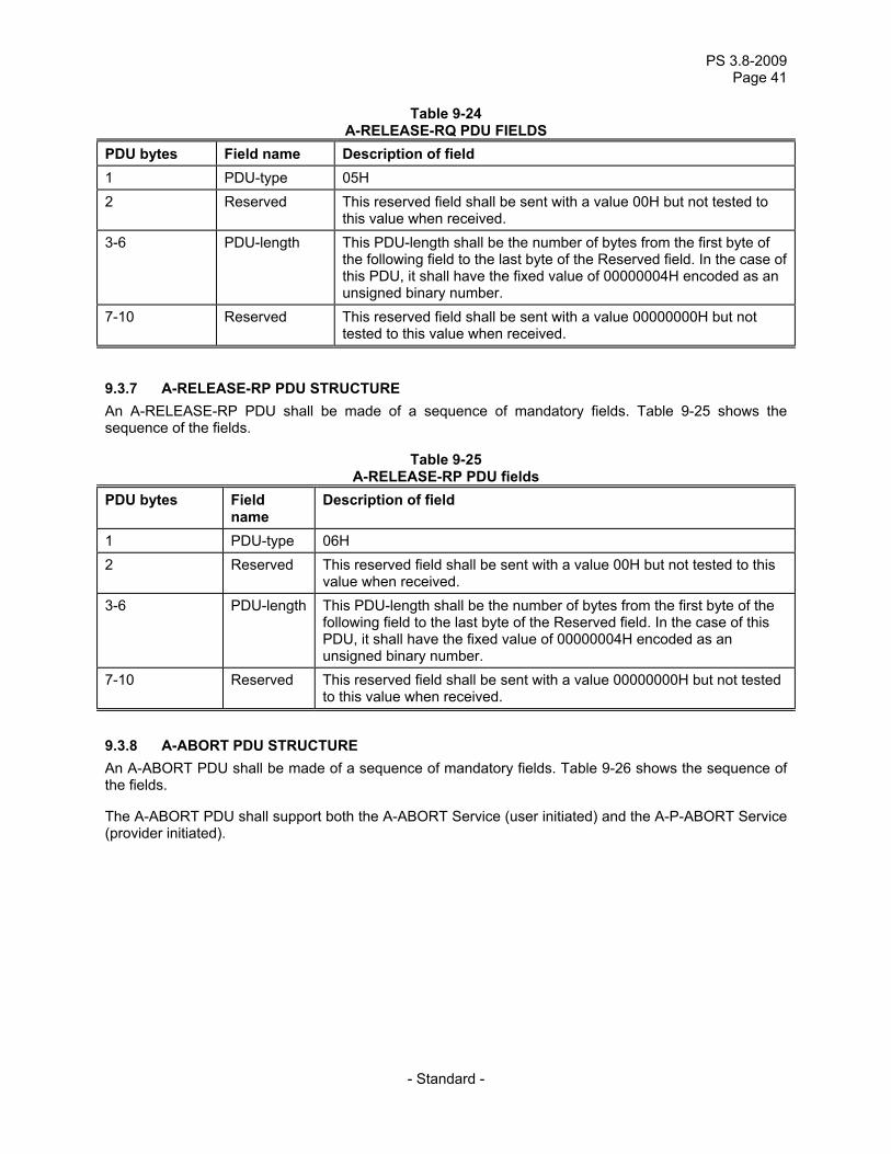
PS 3.8-2009 Page 41
- Standard -
Table 9-24 A-RELEASE-RQ PDU FIELDS
PDU bytes Field name Description of field 1 PDU-type 05H 2 Reserved This reserved field shall be sent with a value 00H but not tested to
this value when received. 3-6 PDU-length This PDU-length shall be the number of bytes from the first byte of
the following field to the last byte of the Reserved field. In the case of this PDU, it shall have the fixed value of 00000004H encoded as an unsigned binary number.
7-10 Reserved This reserved field shall be sent with a value 00000000H but not tested to this value when received.
9.3.7 A-RELEASE-RP PDU STRUCTURE An A-RELEASE-RP PDU shall be made of a sequence of mandatory fields. Table 9-25 shows the sequence of the fields.
Table 9-25 A-RELEASE-RP PDU fields
PDU bytes Field name
Description of field
1 PDU-type 06H 2 Reserved This reserved field shall be sent with a value 00H but not tested to this
value when received. 3-6 PDU-length This PDU-length shall be the number of bytes from the first byte of the
following field to the last byte of the Reserved field. In the case of this PDU, it shall have the fixed value of 00000004H encoded as an unsigned binary number.
7-10 Reserved This reserved field shall be sent with a value 00000000H but not tested to this value when received.
9.3.8 A-ABORT PDU STRUCTURE An A-ABORT PDU shall be made of a sequence of mandatory fields. Table 9-26 shows the sequence of the fields.
The A-ABORT PDU shall support both the A-ABORT Service (user initiated) and the A-P-ABORT Service (provider initiated).
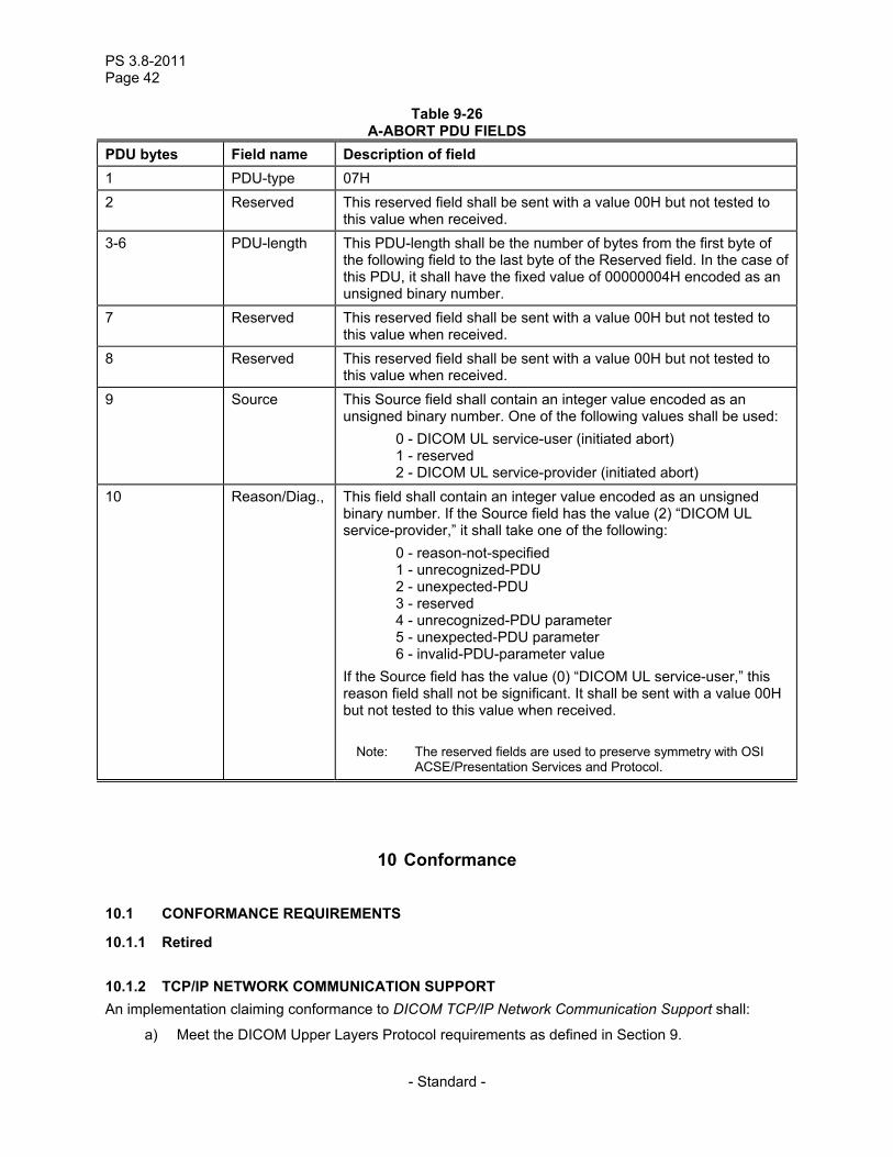
PS 3.8-2011 Page 42
- Standard -
Table 9-26 A-ABORT PDU FIELDS
PDU bytes Field name Description of field 1 PDU-type 07H 2 Reserved This reserved field shall be sent with a value 00H but not tested to
this value when received. 3-6 PDU-length This PDU-length shall be the number of bytes from the first byte of
the following field to the last byte of the Reserved field. In the case of this PDU, it shall have the fixed value of 00000004H encoded as an unsigned binary number.
7 Reserved This reserved field shall be sent with a value 00H but not tested to this value when received.
8 Reserved This reserved field shall be sent with a value 00H but not tested to this value when received.
9 Source This Source field shall contain an integer value encoded as an unsigned binary number. One of the following values shall be used: 0 - DICOM UL service-user (initiated abort) 1 - reserved 2 - DICOM UL service-provider (initiated abort)
10 Reason/Diag., This field shall contain an integer value encoded as an unsigned binary number. If the Source field has the value (2) “DICOM UL service-provider,” it shall take one of the following: 0 - reason-not-specified 1 - unrecognized-PDU 2 - unexpected-PDU 3 - reserved 4 - unrecognized-PDU parameter 5 - unexpected-PDU parameter 6 - invalid-PDU-parameter value If the Source field has the value (0) “DICOM UL service-user,” this reason field shall not be significant. It shall be sent with a value 00H but not tested to this value when received.
Note: The reserved fields are used to preserve symmetry with OSI ACSE/Presentation Services and Protocol.
10 Conformance
10.1 CONFORMANCE REQUIREMENTS
10.1.1 Retired 10.1.2 TCP/IP NETWORK COMMUNICATION SUPPORT An implementation claiming conformance to DICOM TCP/IP Network Communication Support shall:
a) Meet the DICOM Upper Layers Protocol requirements as defined in Section 9.
PS 3.8-2009 Page 43
- Standard -
b) Use registered Application Context Names, Abstract Syntax Names and Transfer Syntax Names as defined for OSI Object Identifiers (ISO 8824 and ISO 9834-1).
Note: Annex F defines the DICOM Upper Layer Protocol encoding for the Application Context Names, Abstract
Syntax Names, and Transfer Syntax Names. ISO 8825 defined encoding is not used.
c) Use one of the published and approved RFCs defining the operation of TCP/IP over specific physical networks.
10.2 CONFORMANCE STATEMENT
An implementation claiming conformance to DICOM for communication support in a networked environment shall state DICOM V3.0 TCP/IP Network Communication Support with the list of physical networks and corresponding relevant implementation information. This implies that the conformance requirements defined in Section 10.1.2 are met.
PS 3.8-2011 Page 44
- Standard -
Annex A Application context names (Informative)
A.1 APPLICATION CONTEXT DEFINITION
An application context explicitly defines the set of application service elements, related options and any other information necessary for the interworking of Application Entities on an association. The usage of the application context is defined in PS 3.7.
Two Application Entities when establishing an association agree on an application context. The requestor of an association proposes an Application Context Name and the acceptor returns either the same or a different Application Context Name. The returned name specifies the application context to be used for this association. The offer of an alternate application context by the acceptor provides a mechanism for limited negotiation. If the requestor cannot operate in the acceptor's application context, it will issue an A-Abort request primitive. Such a negotiation will facilitate the introduction of future versions of the DICOM Application Entity.
A.2 DICOM APPLICATION CONTEXT NAME ENCODING AND REGISTRATION
The Application Context Name structure is based on the OSI Object Identification (numeric form) as defined by ISO 8824. Application Context Names are registered values as defined by ISO 9834-1 to ensure global uniqueness. They are encoded as defined in Annex F when the TCP/IP network communication support is used as defined in Section 9.
A.2.1 DICOM registered application context names The organization responsible for the definition and registration of DICOM Application Context Names is NEMA. NEMA guarantees uniqueness for all DICOM Application Context Names. A choice of DICOM registered Application Context Names related to the DICOM Application Entities, as well as the associated negotiation rules, are defined in PS 3.7.
A.2.2 Retired
PS 3.8-2009 Page 45
- Standard -
Annex B Abstract and transfer syntaxes (Informative)
B.1 ABSTRACT SYNTAX DEFINITION
An Abstract Syntax is the specification of Application Layer data elements with associated semantics or Application Layer protocol control information by using notation rules which are independent of the encoding technique used to represent them.
Note: In particular, it allows the communicating Application Entities to negotiate an agreed set of DICOM Data Elements (e.g. from a specific version of the Data Dictionary) and/or Information Object Class definitions.
B.2 TRANSFER SYNTAX DEFINITION
A Transfer Syntax is a set of encoding rules able to unambiguously represent the data elements defined by one or more Abstract Syntaxes. In particular, negotiation of Transfer Syntaxes allows the communicating Application Entities to agree on the encoding techniques they are able to support (e.g. byte ordering, compression, etc.).
B.3 DICOM ABSTRACT AND TRANSFER SYNTAX NAMES ENCODING AND REGISTRATION
The Abstract and Transfer Syntax Name structure is based on the OSI Object Identification (numeric form) as defined by ISO 8824. Abstract and Transfer Syntax Names are registered values as defined by ISO 9834-1 to ensure global uniqueness. Abstract and Transfer Syntax Names are encoded as defined in ISO 8825 (Object Identifiers of numeric form) when the OSI network communication support is used as defined in Section 8. They are encoded as defined in Annex F when the TCP/IP network communication support is used as defined in Section 9.
B.3.1 DICOM registered abstract and transfer syntax names The organization responsible for the definition and registration of DICOM Abstract and Transfer Syntax Names is NEMA. NEMA guarantees uniqueness for all DICOM Abstract and Transfer Syntax Names. A choice of DICOM registered Abstract and Transfer Syntax Names related to a specific version of the DICOM Application Entities, as well as the associated negotiation rules, are defined in PS 3.4 for Abstract Syntaxes and PS 3.5 for Transfer Syntaxes.
B.3.2 Privately defined abstract and transfer syntax names Privately defined Abstract and Transfer Syntax Names may also be used, however, they will not be registered by NEMA. Organizations that define private Abstract and Transfer Syntax Names are responsible to obtain their proper registration defined for OSI Object Identifiers. National Standards Organizations representing a number of countries (e.g. UK, France, Germany, Japan, USA, etc.) to the International Standards Organization act as a registration authority as defined by ISO 9834-1.
Note: For example, in the USA, ANSI assigns (for a fee) Organization Identifiers to any requesting organization. This identifier is made of a series of four numeric components; 1 (identifies ISO), 2 (identifies the ISO member bodies branch), 840 (identifies ANSI as the ISO member body representing the USA), and xxxxxx (identifies a specific organization and is issued by ANSI). Such an identifier may be used by the identified organization as a root to which it may add a suffix made of one or more numeric components. The identified organization accepts the responsibility to properly register these suffixes to ensure uniqueness.

PS 3.8-2011 Page 46
- Standard -
Annex C DICOM addressing (Normative)
C.1 DICOM APPLICATION ENTITY TITLES
A DICOM Application Entity Title uniquely identifies a service or application on a specific system in the network. Application Entity Titles are independent of network topology so a device may be physically moved while its corresponding Application Entity Title may remain the same. See PS 3.5 for the encoding of DICOM Application Entity Titles.
Note: DICOM Application Entity Title was called Logical Address in the ACR-NEMA Standard. DICOM Application Entity Titles are used in three instances of communication:
a) to identify the Called/Calling Application Entities. They are used to establish an association and to ensure that the association is established with the expected application.
b) to identify the originator and intended destination of DICOM Retrieve Services (see PS 3.4). They are conveyed in DICOM Commands with messages of the DIMSE C-MOVE and C-STORE Services exchanged over an established association.
c) to identify the location of a Retrieve Service SCP for one or more SOP Instances. They are conveyed in DICOM DataSets of various services.
C.2 NAMING AND ADDRESSING USAGE RULES
DICOM Application Entity Titles are used in the Called/Calling Application Entity Title fields of the Upper Layer Service, in the Move Destination and Move Originator Application Entity Title data elements in the DICOM Message Command Set, and in various Attributes of the DICOM Message Data Set.
Notes: 1. A single Application Entity Title can be associated with multiple network addresses assigned to a single system (e.g., multi-homed host).
2. A single Application Entity Title can be associated with multiple TCP Ports using the same or different IP Addresses.
3. A single network access point (IP Address and TCP Port) can support multiple Application Entity Titles.
A DICOM system on a network may support several application processes identified by different DICOM Application Entity Titles.
Upon receiving an association request, the Called Application Entity Title shall be validated so an association can be rejected when the corresponding local application does not exist.
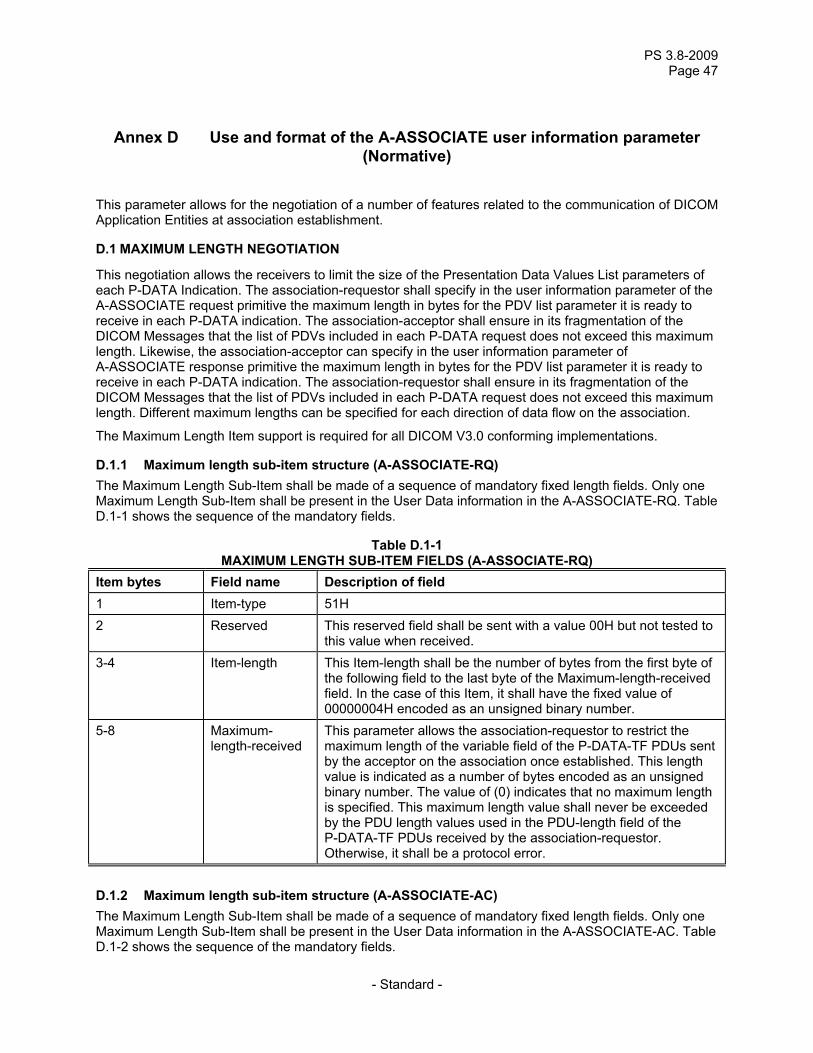
PS 3.8-2009 Page 47
- Standard -
Annex D Use and format of the A-ASSOCIATE user information parameter (Normative)
This parameter allows for the negotiation of a number of features related to the communication of DICOM Application Entities at association establishment.
D.1 MAXIMUM LENGTH NEGOTIATION
This negotiation allows the receivers to limit the size of the Presentation Data Values List parameters of each P-DATA Indication. The association-requestor shall specify in the user information parameter of the A-ASSOCIATE request primitive the maximum length in bytes for the PDV list parameter it is ready to receive in each P-DATA indication. The association-acceptor shall ensure in its fragmentation of the DICOM Messages that the list of PDVs included in each P-DATA request does not exceed this maximum length. Likewise, the association-acceptor can specify in the user information parameter of A-ASSOCIATE response primitive the maximum length in bytes for the PDV list parameter it is ready to receive in each P-DATA indication. The association-requestor shall ensure in its fragmentation of the DICOM Messages that the list of PDVs included in each P-DATA request does not exceed this maximum length. Different maximum lengths can be specified for each direction of data flow on the association.
The Maximum Length Item support is required for all DICOM V3.0 conforming implementations.
D.1.1 Maximum length sub-item structure (A-ASSOCIATE-RQ) The Maximum Length Sub-Item shall be made of a sequence of mandatory fixed length fields. Only one Maximum Length Sub-Item shall be present in the User Data information in the A-ASSOCIATE-RQ. Table D.1-1 shows the sequence of the mandatory fields.
Table D.1-1 MAXIMUM LENGTH SUB-ITEM FIELDS (A-ASSOCIATE-RQ)
Item bytes Field name Description of field 1 Item-type 51H 2 Reserved This reserved field shall be sent with a value 00H but not tested to
this value when received. 3-4 Item-length This Item-length shall be the number of bytes from the first byte of
the following field to the last byte of the Maximum-length-received field. In the case of this Item, it shall have the fixed value of 00000004H encoded as an unsigned binary number.
5-8 Maximum- length-received
This parameter allows the association-requestor to restrict the maximum length of the variable field of the P-DATA-TF PDUs sent by the acceptor on the association once established. This length value is indicated as a number of bytes encoded as an unsigned binary number. The value of (0) indicates that no maximum length is specified. This maximum length value shall never be exceeded by the PDU length values used in the PDU-length field of the P-DATA-TF PDUs received by the association-requestor. Otherwise, it shall be a protocol error.
D.1.2 Maximum length sub-item structure (A-ASSOCIATE-AC) The Maximum Length Sub-Item shall be made of a sequence of mandatory fixed length fields. Only one Maximum Length Sub-Item shall be present in the User Data information in the A-ASSOCIATE-AC. Table D.1-2 shows the sequence of the mandatory fields.

PS 3.8-2011 Page 48
- Standard -
Table D.1-2 Maximum length sub-item fields (A-ASSOCIATE-AC)
Item bytes Field name Description of field 1 Item-type 51H 2 Reserved This reserved field shall be sent with a value 00H but not tested to this
value when received. 3-4 Item-length This Item-length shall be the number of bytes from the first byte of the
following field to the last byte of the Maximum-length-received field. In the case of this Item, it shall have the fixed value of 00000004H encoded as an unsigned binary number.
5-8 Maximum- length-received
This parameter allows the association-acceptor to restrict the maximum length of the variable field of the P-DATA-TF PDUs sent by the requestor on the association once established. This length value is indicated as a number of bytes encoded as an unsigned binary number. The value of (0) indicates that no maximum length is specified. This maximum length value shall never be exceeded by the PDU length values used in the PDU-length field of the P-DATA-TF PDUs received by the association-acceptor. Otherwise, it shall be a protocol error.
D.2 EXTENDED USER INFORMATION NEGOTIATION
The user information parameter, of the A-ASSOCIATE primitive, can be extended to support the negotiation needs of DICOM Application Entities using the UL Service. This will result in the definition of specific user information sub-items. These sub-items shall be assigned unique item-type values registered in PS 3.7.
Notes: 1. The values of the Sub-Items types in the User Information Field are assigned by this standard in the range of 51H through FFH. Sub-Item values are defined by PS 3.7 and PS 3.8.
2. Succeeding editions of the Standard may define additional user information Sub-Items in a manner that does not affect the semantics of previously defined Sub-Items. Association acceptors compliant to an earlier edition of the Standard are required to ignore such unrecognized user information Sub-Items and not reject an Association because of their presence.
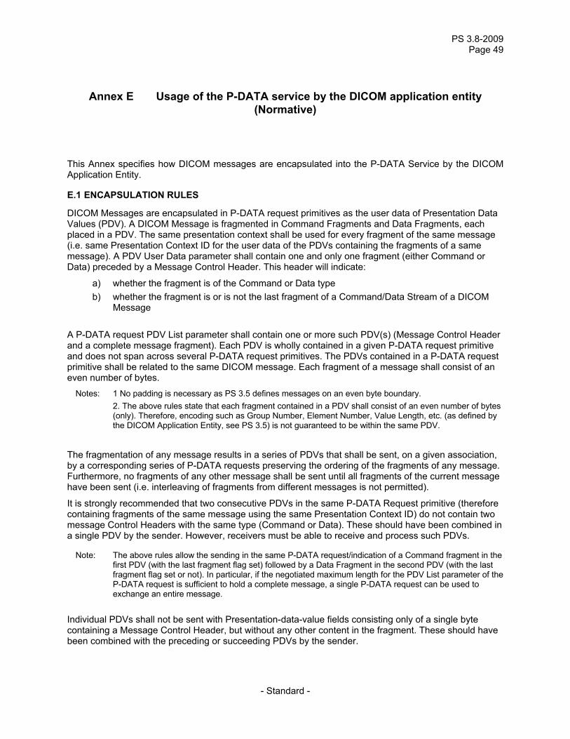
PS 3.8-2009 Page 49
- Standard -
Annex E Usage of the P-DATA service by the DICOM application entity (Normative)
This Annex specifies how DICOM messages are encapsulated into the P-DATA Service by the DICOM Application Entity.
E.1 ENCAPSULATION RULES
DICOM Messages are encapsulated in P-DATA request primitives as the user data of Presentation Data Values (PDV). A DICOM Message is fragmented in Command Fragments and Data Fragments, each placed in a PDV. The same presentation context shall be used for every fragment of the same message (i.e. same Presentation Context ID for the user data of the PDVs containing the fragments of a same message). A PDV User Data parameter shall contain one and only one fragment (either Command or Data) preceded by a Message Control Header. This header will indicate:
a) whether the fragment is of the Command or Data type b) whether the fragment is or is not the last fragment of a Command/Data Stream of a DICOM
Message A P-DATA request PDV List parameter shall contain one or more such PDV(s) (Message Control Header and a complete message fragment). Each PDV is wholly contained in a given P-DATA request primitive and does not span across several P-DATA request primitives. The PDVs contained in a P-DATA request primitive shall be related to the same DICOM message. Each fragment of a message shall consist of an even number of bytes.
Notes: 1 No padding is necessary as PS 3.5 defines messages on an even byte boundary. 2. The above rules state that each fragment contained in a PDV shall consist of an even number of bytes
(only). Therefore, encoding such as Group Number, Element Number, Value Length, etc. (as defined by the DICOM Application Entity, see PS 3.5) is not guaranteed to be within the same PDV.
The fragmentation of any message results in a series of PDVs that shall be sent, on a given association, by a corresponding series of P-DATA requests preserving the ordering of the fragments of any message. Furthermore, no fragments of any other message shall be sent until all fragments of the current message have been sent (i.e. interleaving of fragments from different messages is not permitted).
It is strongly recommended that two consecutive PDVs in the same P-DATA Request primitive (therefore containing fragments of the same message using the same Presentation Context ID) do not contain two message Control Headers with the same type (Command or Data). These should have been combined in a single PDV by the sender. However, receivers must be able to receive and process such PDVs.
Note: The above rules allow the sending in the same P-DATA request/indication of a Command fragment in the first PDV (with the last fragment flag set) followed by a Data Fragment in the second PDV (with the last fragment flag set or not). In particular, if the negotiated maximum length for the PDV List parameter of the P-DATA request is sufficient to hold a complete message, a single P-DATA request can be used to exchange an entire message.
Individual PDVs shall not be sent with Presentation-data-value fields consisting only of a single byte containing a Message Control Header, but without any other content in the fragment. These should have been combined with the preceding or succeeding PDVs by the sender.
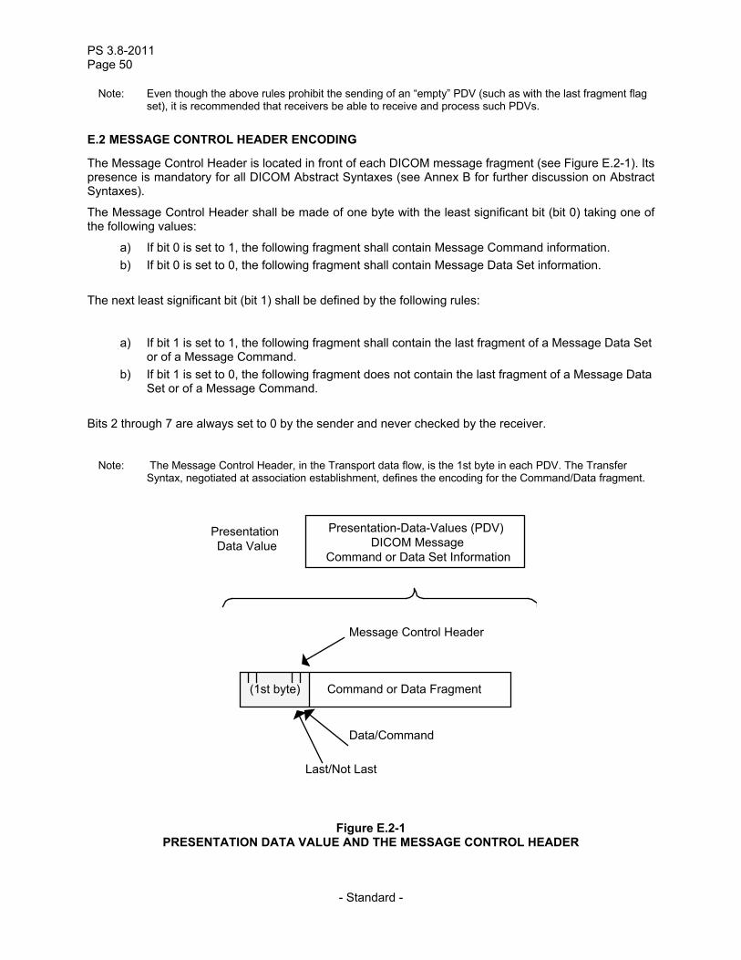
PS 3.8-2011 Page 50
- Standard -
Note: Even though the above rules prohibit the sending of an “empty” PDV (such as with the last fragment flag set), it is recommended that receivers be able to receive and process such PDVs.
E.2 MESSAGE CONTROL HEADER ENCODING
The Message Control Header is located in front of each DICOM message fragment (see Figure E.2-1). Its presence is mandatory for all DICOM Abstract Syntaxes (see Annex B for further discussion on Abstract Syntaxes).
The Message Control Header shall be made of one byte with the least significant bit (bit 0) taking one of the following values:
a) If bit 0 is set to 1, the following fragment shall contain Message Command information. b) If bit 0 is set to 0, the following fragment shall contain Message Data Set information.
The next least significant bit (bit 1) shall be defined by the following rules:
a) If bit 1 is set to 1, the following fragment shall contain the last fragment of a Message Data Set or of a Message Command.
b) If bit 1 is set to 0, the following fragment does not contain the last fragment of a Message Data Set or of a Message Command.
Bits 2 through 7 are always set to 0 by the sender and never checked by the receiver.
Note: The Message Control Header, in the Transport data flow, is the 1st byte in each PDV. The Transfer
Syntax, negotiated at association establishment, defines the encoding for the Command/Data fragment.
Presentation-Data-Values (PDV)DICOM Message
Command or Data Set Information
PresentationData Value
Message Control Header
(1st byte) Command or Data Fragment
Last/Not Last
Data/Command
Figure E.2-1 PRESENTATION DATA VALUE AND THE MESSAGE CONTROL HEADER
PS 3.8-2009 Page 51
- Standard -
Annex F DICOM UL encoding rules for application contexts, abstract syntaxes, transfer syntaxes
(Normative)
F.1 ENCODING RULES
Application Context Names, Abstract Syntax Names, Transfer Syntax Names, and Service Class UIDs are OSI Object Identifiers in a numeric form as defined by ISO 8824. The encoding of these names in the DICOM UL protocol is specified in this Annex.
Each component of a Name or UID is encoded as an ISO 646:1990-Basic G0 Set Numeric String of bytes (characters 0-9). Leading 0's of each component are not significant and shall not be sent. Components shall not be padded. Components shall be separated by the character “.” (2EH). “Null” components (no numeric value between two separators) shall not exist. Components with the value zero (0) shall be encoded as (nnn.0.ppp). No separator nor padding shall be present before the first digit of the first component or after the last digit of the last component.
Notes: 1 The string “1.2.840.123456.0.21.4" encoded as an ISO 646:1990-Basic G0 Set character string conveys the following UID or Name with the following sequence of Object Identifier components: { (1), (2), (840), (123456), (0), (21), (4) }.
2 The above rules have been made to simplify performing the comparison of UIDs. DICOM Application Context Names (root plus suffix) shall not exceed 64 total characters (digits and separators between components).
DICOM Abstract and Transfer Syntax Names (root plus suffix) shall not exceed 64 total characters (digits and separators between components).
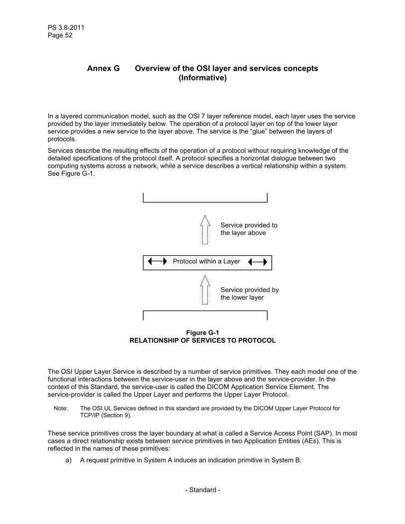
PS 3.8-2011 Page 52
- Standard -
Annex G Overview of the OSI layer and services concepts (Informative)
In a layered communication model, such as the OSI 7 layer reference model, each layer uses the service provided by the layer immediately below. The operation of a protocol layer on top of the lower layer service provides a new service to the layer above. The service is the “glue” between the layers of protocols.
Services describe the resulting effects of the operation of a protocol without requiring knowledge of the detailed specifications of the protocol itself. A protocol specifies a horizontal dialogue between two computing systems across a network, while a service describes a vertical relationship within a system. See Figure G-1.
Service provided to the layer above
Protocol within a Layer
Service provided by the lower layer
Figure G-1 RELATIONSHIP OF SERVICES TO PROTOCOL
The OSI Upper Layer Service is described by a number of service primitives. They each model one of the functional interactions between the service-user in the layer above and the service-provider. In the context of this Standard, the service-user is called the DICOM Application Service Element. The service-provider is called the Upper Layer and performs the Upper Layer Protocol.
Note: The OSI UL Services defined in this standard are provided by the DICOM Upper Layer Protocol for TCP/IP (Section 9).
These service primitives cross the layer boundary at what is called a Service Access Point (SAP). In most cases a direct relationship exists between service primitives in two Application Entities (AEs). This is reflected in the names of these primitives:
a) A request primitive in System A induces an indication primitive in System B.

PS 3.8-2009 Page 53
- Standard -
b) If an indication primitive in System B requires a reply, a response primitive may be issued at the Service Access Point (SAP) in System B. This response primitive will induce a confirmation primitive in System A.
The different types of service primitives and their relationship are shown in Figure G-2. The dotted lines represent the exchange of Protocol Data Units that are triggered by request/response primitives or generated indication/confirmation primitives.
Application Entity inSystem B
DICOM ULService Provider
Service Access Point(SAP) in System A
RequestPrimitive
ConfirmationPrimitive
ResponsePrimitive
IndicationPrimitive
Application Entity inSystem B
Service Access Point(SAP) in System A
Figure G-2 SERVICE DESCRIPTION CONVENTIONS

PS 3.8-2011 Page 54
- Standard -
Annex H Index of Item and PDU Types (Informative)
01H............ 34 02H............ 37 03H............ 40 04H............ 41 05H............ 42 06H............ 42 07H............ 43 10H............ 35 20H............ 35 21H............ 38 30H............ 36 40H............ 36, 39 50H............ 37, 39 51H............ 48, 49
![2010-2011 [File size: 3.8 MB]](https://static.fdocuments.in/doc/165x107/589ef1fc1a28ab724a8c1b82/2010-2011-file-size-38-mb.jpg)