DIAL INDICATORS A S F ECHANICAL DIAL INDICATORS A · Basically, all dial indicators used worldwide...
27
ELECTRONIC INDICATORS/INDICATOR HOLDERS Accurate, rugged, versatile, convenient to use and inexpensive – for these reasons and more, mechanical dial indicators with bottom plungers are the measurement workhorses of industrial production. Electronic indicators have an unmatched ability for the accurate recording of a great amount of measurement data which is used in a variety of Statistical Process Control (SPC) operations. The first part of this section shows our complete line of mechanical/ analog dial indicators – over 180 models to give you the widest selection in the industry. Our comparison guide, following these introduction pages, has all the significant specifications to help you make your selection. MECHANICAL DIAL INDICATORS AND ATTACHMENTS COMPARING AGD DESIGN SPECIFICATIONS WITH OTHERS 1/4" (6.35) 3/4" (19) 1/4" (6.4) 1/4" (6.35) .375" (9.5)* #4-48 (M 2.5) THREAD** * There are two major differences between American Gage Design and other specifications. The first is the stem diameter. AGD specifies .375" (9.5mm) and some other standards specify an 8mm (.315") diameter. International specifications allow for either one and we can furnish both diameters. The .375" (9.5mm) diameter provides a little more protection for the rack when clamped on the stem – 8mm stems are available on any model, please specify when ordering. ** The other difference is the contact thread. AGD specifies a #4-48 thread. Other standards specify a metric thread, #M2.5. DIAL INDICATORS APPLICATION SPECIFICATION FACTORS 1. Regular analog styles with indicating hands are more readable than digital styles when the measurements are being visually monitored by an operator. 2. Select the dial size that gives you the readability you need. We offer five regular dial sizes which will fit most applications that have both space limitations and readability requirements. 3. Choose the accuracy and readout you need – don't select a .0001" (or 0.001mm) readout if .001" (or 0.01mm) will do your job. 4. Electronic styles are best when the measurement data needs to be collected, printed out or stored for future use. 5. Consider any special features you may need – inch or millimeter reading, special shockless movement, antimagnetic, long range, long stem, special backs, special contacts, special holders, etc. If you don't see what you need, please contact our Special Order Department. Even though we have a broad line of indicators to tackle most jobs, we also do a lot of special design, catering to the specific needs of our customers – challenge us! 6. Starrett indicators are made to American Gage Design Specifications (AGD). These specifications were developed in 1945 at the request of the U.S. Commerce Department through the National Bureau of Standards – now the National Institute of Standards and Technology (NIST). These specifications provide the dimensions to allow interchangeability between indicators of different manufacturers in fixturing. As you will see, these dimensions pertain to sizes for space consideration and for holding. Other countries have made their own design specifications which we can also furnish. However, the AGD design is probably more widely used, simply because it was the first standard created. 7. Basically, all dial indicators used worldwide fall into the following size ranges which relate to bezel diameters. Size 0 is a smaller dial indicator, having its own dimensions. Sizes 1 through 4 are AGD sizes. These sizes and the AGD dimensions are essentially the same for all manufacturers, except as noted. 8. Accuracy – All indicators should be "loaded" 1/8-1/4 of a turn before testing or measuring. Starrett dial indicators meet or exceed all known performance specifications. Most accuracies are specified plus or minus one graduation over the full range. This basically means a 2-1/2 turn range. Longer ranges have slightly wider tolerances. Starrett indicators are at least that accurate, but we are better than that in the final critical measuring zone of "10 o'clock to 2 o'clock" from zero. AGD specifies 2-1/3 turn indicators to cover any particular range. The reason for this is that in an effort to get the most out of the indicator, the operator "loads" it to about 1-1/3 turns and sets zero on his master. The indicator will now show the accurate deviation for a full revolution, plus or minus. 144 INDICATORS AND GAGES
Transcript of DIAL INDICATORS A S F ECHANICAL DIAL INDICATORS A · Basically, all dial indicators used worldwide...

ELECTRONIC INDICATORS/INDICATOR HOLDERS
Accurate, rugged, versatile, convenient to use and inexpensive – for
these reasons and more, mechanical dial indicators with bottom
plungers are the measurement workhorses of industrial production.
Electronic indicators have an unmatched ability for the accurate
recording of a great amount of measurement data which is used in a
variety of Statistical Process Control (SPC) operations.
The first part of this section shows our complete line of mechanical/
analog dial indicators – over 180 models to give you the widest
selection in the industry. Our comparison guide, following these
introduction pages, has all the significant specifications to help you
make your selection.
MECHANICAL DIAL INDICATORS AND ATTACHMENTS
COMPARING AGD DESIGN SPECIFICATIONS WITH OTHERS
1/4"
(6.35)
3/4"
(19)
1/4"
(6.4)
1/4"
(6.35)
.375"
(9.5)*
#4-48 (M 2.5)
THREAD**
* There are two major differences between American Gage Design and other specifications.
The first is the stem diameter. AGD specifies .375" (9.5mm) and some other standards specify
an 8mm (.315") diameter. International specifications allow for either one and we can furnish
both diameters. The .375" (9.5mm) diameter provides a little more protection for the rack when
clamped on the stem – 8mm stems are available on any model, please specify when ordering.
** The other difference is the contact thread. AGD specifies a #4-48 thread. Other standards
specify a metric thread, #M2.5.
DIAL INDICATORS APPLICATION SPECIFICATION FACTORS
1. Regular analog styles with indicating hands are more readable
than digital styles when the measurements are being visually
monitored by an operator.
2. Select the dial size that gives you the readability you need.
We offer five regular dial sizes which will fit most applications
that have both space limitations and readability requirements.
3. Choose the accuracy and readout you need – don't select a
.0001" (or 0.001mm) readout if .001" (or 0.01mm) will do your
job.
4. Electronic styles are best when the measurement data needs
to be collected, printed out or stored for future use.
5. Consider any special features you may need – inch
or millimeter reading, special shockless movement,
antimagnetic, long range, long stem, special backs, special
contacts, special holders, etc. If you don't see what you need,
please contact our Special Order Department. Even though
we have a broad line of indicators to tackle most jobs, we also
do a lot of special design, catering to the specific needs of our
customers – challenge us!
6. Starrett indicators are made to American Gage Design
Specifications (AGD). These specifications were developed in
1945 at the request of the U.S. Commerce Department through
the National Bureau of Standards – now the National Institute
of Standards and Technology (NIST). These specifications
provide the dimensions to allow interchangeability between
indicators of different manufacturers in fixturing. As you will
see, these dimensions pertain to sizes for space consideration
and for holding. Other countries have made their own design
specifications which we can also furnish. However, the AGD
design is probably more widely used, simply because it was
the first standard created.
7. Basically, all dial indicators used worldwide fall into the
following size ranges which relate to bezel diameters. Size 0
is a smaller dial indicator, having its own dimensions. Sizes 1
through 4 are AGD sizes. These sizes and the AGD dimensions
are essentially the same for all manufacturers, except as
noted.
8. Accuracy – All indicators should be "loaded" 1/8-1/4 of
a turn before testing or measuring. Starrett dial indicators
meet or exceed all known performance specifications. Most
accuracies are specified plus or minus one graduation over
the full range. This basically means a 2-1/2 turn range. Longer
ranges have slightly wider tolerances. Starrett indicators are
at least that accurate, but we are better than that in the final
critical measuring zone of "10 o'clock to 2 o'clock" from zero.
AGD specifies 2-1/3 turn indicators to cover any particular
range. The reason for this is that in an effort to get the most
out of the indicator, the operator "loads" it to about 1-1/3
turns and sets zero on his master. The indicator will now show
the accurate deviation for a full revolution, plus or minus.
144
IND
ICATO
RS A
ND G
AGES
DESIGN FEATURES
• Rugged and simple unit construction with a
"universally fitting" design as shown
• One gear unit assembly fits AGD Group 2 (our 25
Indicators), AGD Group 3 (our 655 Indicators) and AGD
Group 4 (our 656 Indicators)
• The gear unit is constructed of a massive single
bridge and plate assembly with a hardened stainless
steel gear train
• All gear trains are fully jeweled for sensitivity,
smoothness and life. (We do provide 1/2" and 1"
range models with plain bronze bearings)
• The case is light but sturdy, with a hardened, precision
stainless steel rack that rides in bronze bushings. Size
Groups 0 and 1 indicators are of similar construction
but smaller in size.
• Hardened stainless steel bottom stems can be held in
fixtures without cramping rack action
• Easy readability with the best, balanced style of
graduation and number combination. (Too thick and
accuracy suffers; too thin and readability suffers)
• Balanced and tapered hands are easy to follow
• Special non-shock mechanism (can be furnished on
most styles) is ideal for when an indicator may be
subjected to repeated and excessive shocks
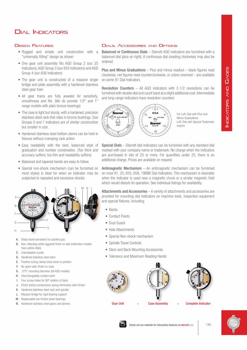
DIALS, ACCESSORIES AND OPTIONS
Balanced or Continuous Dials – Starrett AGD indicators are furnished with a
balanced dial (plus on right). A continuous dial (reading clockwise) may also be
ordered.
Plus and Minus Graduations – Plus and minus readout – black figures read
clockwise, red figures read counterclockwise, or colors reversed – are available
on some 81 Dial Indicators.
Revolution Counters – All AGD indicators with 2-1/2 revolutions can be
furnished with double dial and count hand at a slight additional cost. Intermediate
and long-range indicators have revolution counters
Special Dials – Starrett dial indicators can be furnished with any standard dial
marked with your company name or trademark. No charge when the indicators
are purchased in lots of 25 or more. For quantities under 25, there is an
additional charge. Prices are available on request.
Antimagnetic Mechanism – An antimagnetic mechanism can be furnished
on most 81, 25, 655, 656, 196B6 Dial Indicators. This mechanism is desirable
when the indicator is used near a magnetic chuck or a similar magnetic field
which would disturb its operation. See individual listings for availability.
Attachments and Accessories – A variety of attachments and accessories are
provided for mounting dial indicators on machine tools, inspection equipment
and special fixtures, including:
• Backs
• Contact Points
• Dust Guard
• Hole Attachments
• Special Non-shock mechanism
• Spindle Travel Controls
• Stem and Back Mounting Accessories
• Tolerance and Maximum Reading Hands
Far Left: Dial with Plus and
Minus Graduations
Left: Dial with Special Trademark
Imprint
Gear Unit + Case Assembly = Complete Indicator
DIAL INDICATORS
A. Sharp bezel serrations for positive grip
B. Non-reflecting white eggshell finish on dial (millimeter models
have yellow dials)
C. Unbreakable crystal
D. Hardened stainless steel stem
E. Positive-acting clamp locks bezel in position
F. No-glare satin finish on case
G. .375" mounting diameter (all AGD models)
H. Interchangeable contact point
I. Four screw holes for 90º rotation of back
J. Direct acting compression spring eliminates side friction
K. Hardened stainless steel rack and spindle
L. Massive bridge for rigid bearing support
M. Replaceable low friction jewel bearings
N. Hardened stainless steel gears and pinions
A
B
C
D
H
E J M N L
F
G
K
I
145Check out our website for interactive features at starrett.com
IND
ICATO
RS A
ND G
AGES

80 Miniature Dial Indicators
GraduationRange
Dial Reading Cat. No. EDPOne Rev. Total
.0001".004" .010" 0-2-0 80-114J 55891
.010" .025" 0-5-0 80-111J 67714
.0005" .020" .050" 0-10-0 80-134J 55892
.001" .040" .100" 0-20-0 80-144J 55893
1/4" (6.3)
9/16" (14.5)
Dimensions with lug-on-center back
15/64" (6)
19/32"
(15)1-3/16"(30)
1/8" (3)
.2185" (5.5)
1-1/8"
(30)1-1/4"
(32)
7/32" (5.5)
1/4" (6.3)
3/4" (19)
Free drafting template available for this size.
Write The L. S. Starrett Co. at:
121 Crescent Street
Athol, MA 01331.
80-114J 80-134J 80-144J
80 MINIATURE DIAL INDICATORS
AND ACCESSORIES
ANSI GROUP 0RANGES UP TO .100"1-1/4" BEZEL, 7/32" STEM
Similar in design to AGD dial indicators, these miniatures are built for
gaging dimensions in tight places. Equipped with high precision, low
friction movements, they are made in four models, all with frictionally
adjustable bezels for quick, positive zero setting. No-glare, white
eggshell finish dials. Black bezel, silver finish on case. Furnished with
balanced dial, jeweled bearings and lug-on-center back.
80SB split bushing available .219" to 3/8".
DIAL INDICATORS
146
IND
ICATO
RS A
ND G
AGES

80-111J
Description Part No. EDPRegular Contact Point PT25044 72023
Button Contact Point PT25159 72024
Cone Contact Point PT25161 72025
Flat Contact Point PT25160 72026
Flat Back PT25079 72028
Screw-Type Lug Back PT25071 72030
Lug-on Center Back PT25053 72027
Adjustable Bracket Back PT25157 72029
Post-Type Lug Back PT25158 72031
CONTACT POINTS
The regular contact point is furnished standard on all 80 Dial
Indicators. Button, cone and flat contact points are available
individually, as listed. All have #0-80 thread.
3/32"
3/32" R1/8"
DIA 3/8"
DIA
1/8"
1/4" R
PT25044 Regular Contact Point(Standard on all 80 Dial Indicators)
PT25159 Button Contact Point
1/8"
DIA
7/16"
.015" R
1/8"
DIA
1/4"
PT25161 Cone Contact Point PT25160 Flat Contact Point
BACKS
The lug-on-center back is furnished standard on all 80 Dial
Indicators.
5/16"
5/16" DIA
7/32" DIA
3/8"
1-1/8"
DIA
PT25158 Post-Type Lug Back PT25079 Flat Back1/4"
45º
1/2"
9/16"
1/4" DIA#1/4-28
THREAD
1/2" DIA
9/16"
PT25053 Lug-on-Center Back (Standard on all 80 Dial Indicators)
PT25071 Screw-Type Lug Back
11/16"
DIA#8-32
THREAD
1/8"
3/8"
1/4"
PT25157 Adjustable Bracket BackNOTE: Contact points and backs can be ordered individually. Order by part number/EDP number.
147Check out our website for interactive features at starrett.com
IND
ICATO
RS A
ND G
AGES

81, 25, 655 AND 656
AGD DIAL INDICATORS
This comparison table is an aid to help you
find the indicator with the specific graduations
and ranges you are looking for. Refer to the
following pages for the exact catalog number
and EDP number.
81, 25, 655 and 656 AGD Dial Indicators (White Dials Furnished Standard)
GraduationRange
Dial ReadingGroup 1 Group 2 Group 3 Group 4
One Rev. Total 81 Indictators 25 Indicators 655 Indicators 656 Indicators
.00005" .006" .015"0-3-0 25-109 656-109
0-6 25-209 656-209
.0001" .006" .015" 0-3-0 25-116
.0001" .008" .020"0-4-0 25-118 655-118 656-118
0-8 25-218
.0001" .010" .025"0-5-0 81-111 25-111 655-111 656-111
0-10 81-211 25-211 655-211 656-211
.0001" .010" .025"
+0.10 –0.10
81-111-624*
–0.10 +0.10
81-111-630*
.0001" .010" .200"0-5-0 25-511* 655-511* 656-511*
0-10 25-611* 655-611* 656-611*
.0001" .020" .400"0-10-0 656-517*
0-20 656-617*
.00025" .010" .025"0-5-0 81-124 25-124 655-124 656-124
0-10 81-224 25-224 655-224 656-224
.00025" .020" .050"0-10-0 81-128 25-128 655-128 656-128
0-20 81-228 25-228 655-228 656-228
.00025" .030" .075"0-15-0 655-129 656-129
0-30 655-229 656-229
.0005" .020" .050"0-10-0 81-134 25-134 655-134 656-134
0-20 81-234 25-234 655-234 656-234
.0005" .030" .075"0-15-0 81-136 25-136 655-136 656-136
0-30 81-236 25-236 655-236 656-236
.0005" .030" .075"
+0.30 –0.30
81-136-622*
–0.30 +0.30
81-136-623*
.0005" .040" .100"0-20-0 81-138 25-138 655-138 656-138
0-40 81-238 25-238 655-238 656-238
.0005" .050" .125"0-25-0 81-131 25-131 655-131 656-131
0-50 81-231 25-231 655-231 656-231
.0005" .050".500" 0-50 25-431*†
1.000" 0-50 25-631*†
* With revolution counter on dial
† With top lift mechanism
AGD Design Specifications: Bezel Diameters
Design Size GroupMinimum Diameter Maximum DiameterInch mm Inch mm
0 1" 25mm 1-3/8" 35mm
AGD
1 1-3/8" 35mm 2" 50mm
2 2" 50mm 2-3/8" 60mm
3 2-3/8" 60mm 3" 75mm
4 3" 76mm 3-3/4" 95mm
DIAL INDICATORS
Group 43-5/8"
92mm
Group 32-3/4"
70mm
Group 22-1/4"
57mm
Group 11-11/16"
43mm
148
IND
ICATO
RS A
ND G
AGES

81, 25, 655 and 656 AGD Dial Indicators (White Dials Furnished Standard)
GraduationRange
Dial ReadingGroup 1 Group 2 Group 3 Group 4
One Rev. Total 81 Indicators 25 Indicators 655 Indicators 656 Indicators
.001" .020" .050"0-10-0 81-142 25-142 655-142 656-142
0-20 81-242 25-242 655-242 656-242
.001" .030" .075"0-15-0 81-143 25-143 655-143 656-143
0-30 81-243 25-243 655-243 656-243
.001" .030" .075"+0.30, –0.30 81-143-628*
–0.30, +0.30 81-143-629*
.001" .040" .100"0-20-0 81-144 25-144 655-144 656-144
0-40 81-244 25-244 655-244 656-244
.001" .050" .125"0-25-0 81-145 25-145 655-145 656-145
0-50 81-245 25-245 655-245 656-245
.001" .100" .250"0-50-0 81-141 25-141 655-141 656-141
0-100 81-241 25-241 655-241 656-241
.001" .100" .500"0-50-0 25-341/5*† 655-341/5* 656-341/5*
0-100 25-441/5*† 655-441/5* 656-441/5*
.001" .100" 1.000"0-50-0 25-341*† 655-341*† 656-341*†
0-100 25-441*† 655-441*† 656-441*†
.001" .100"
2.000"
0-100
25-2041* 655-2041* 656-2041*
3.000" 25-3041* 655-3041* 656-3041*
4.000" 25-4041* 655-4041* 656-4041*
5.000" 25-5041* 655-5041* 656-5041*
6.000" 656-6041*
7.000" 656-7041*
8.000" 656-8041*
9.000" 656-9041*
10.000" 656-10041*
11.000" 656-11041*
12.000" 656-12041*
81, 25, 655 and 656 AGD Dial Indicators (Yellow Dials Furnished Standard)
0.001mm 0.1mm 0.25mm0-50-0 25-151*
0-100 25-251*
0.002mm 0.2mm 0.5mm0-10-0 81-161 25-161 655-161 656-161
0-20 81-261 25-261 655-261 656-261
0.01mm 1mm 2.5mm0-50-0 81-181 25-181 655-181 656-181
0-100 81-281 25-281 655-281 656-281
0.01mm 1mm 10mm0-50-0 25-381*†
0-100 25-481*
0.01mm 1mm 25mm0-50-0 25-781*†
0-100 25-881*† 655-881*† 656-881*†
0.01mm 1mm 50mm 0-100 25-2081* 655-2081*
0.01mm 1mm 75mm 0-100 25-3081* 655-3081*
0.01mm 1mm 100mm 0-100 25-4081* 655-4081*
0.01mm 1mm 125mm 0-100 25-5081* 655-5081*
* With revolution counter on dial
† With top lift mechanism
149Check out our website for interactive features at starrett.com
IND
ICATO
RS A
ND G
AGES
DIAL INDICATORS
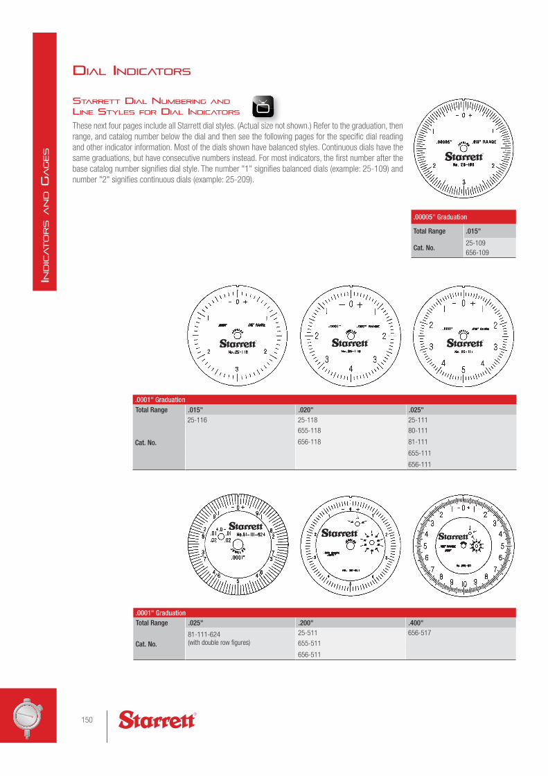
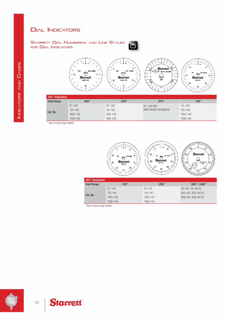
STARRETT DIAL NUMBERING AND LINE STYLES FOR DIAL INDICATORS
These next four pages include all Starrett dial styles. (Actual size not shown.) Refer to the graduation, then
range, and catalog number below the dial and then see the following pages for the specific dial reading
and other indicator information. Most of the dials shown have balanced styles. Continuous dials have the
same graduations, but have consecutive numbers instead. For most indicators, the first number after the
base catalog number signifies dial style. The number "1" signifies balanced dials (example: 25-109) and
number "2" signifies continuous dials (example: 25-209).
.00005" Graduation
Total Range .015"
Cat. No.25-109
656-109
.0001" GraduationTotal Range .015" .020" .025"
Cat. No.
25-116 25-118 25-111
655-118 80-111
656-118 81-111
655-111
656-111
.0001" GraduationTotal Range .025" .200" .400"
Cat. No.81-111-624 (with double row figures)
25-511 656-517
655-511
656-511
150
IND
ICATO
RS A
ND G
AGES
uall sisi eze no

.00025" GraduationTotal Range .025" .050" .075"
Cat. No.
81-124 81-128 655-129
25-124 25-128 656-129
655-124 655-128
656-124 656-128
.0005" GraduationTotal Range .050" .075" .075" .100"
Cat. No.
81-134 81-136 81-136-622 (with double row figures)
81-138
25-134 25-136 25-138
655-134 655-136 655-138
656-134 656-136 656-138
.0005" GraduationTotal Range .125" .500" 1.000"
Cat. No.
81-131 25-431 25-631
25-131
655-131
656-131
151Check out our website for interactive features at starrett.com
IND
ICATO
RS A
ND G
AGES
STARRETT DIAL NUMBERING AND LINE STYLES FOR DIAL INDICATORS
DIAL INDICATORS
.001" GraduationTotal Range .050" .075" .075" .100"
Cat. No.
81-142 81-143 81-143-628 (with double row figures)
81-144
*25-142 25-143 *25-144
*655-142 655-143 *655-144
*656-142 656-143 *656-144
* Also on long range models.
.001" GraduationTotal Range .125" .250" .500", 1.000"
Cat. No.
81-145 81-141 25-441, 25-441/5
*25-145 *25-141 655-441, 655-441/5
*655-145 *655-141 656-441, 656-441/5
*656-145 *656-141
* Also on long range models.
152
IND
ICATO
RS A
ND G
AGES

0.001mm GraduationTotal Range .25mmCat. No. 25-151
0.002mm GraduationTotal Range 0.5mm
Cat. No.
No.81-161
25-161
655-161
656-161
0.005mm GraduationTotal Range 1.25mmCat. No. 25-171
0.01mm GraduationTotal Range 2.5mm 25mm 10mm 50, 75, 100, 125mm
Cat. No.
81-181 25-881 25-381 25-2081
25-181 655-881 25-3081
655-181 656-881 25-4081
656-181 25-5081
153Check out our website for interactive features at starrett.com
IND
ICATO
RS A
ND G
AGES
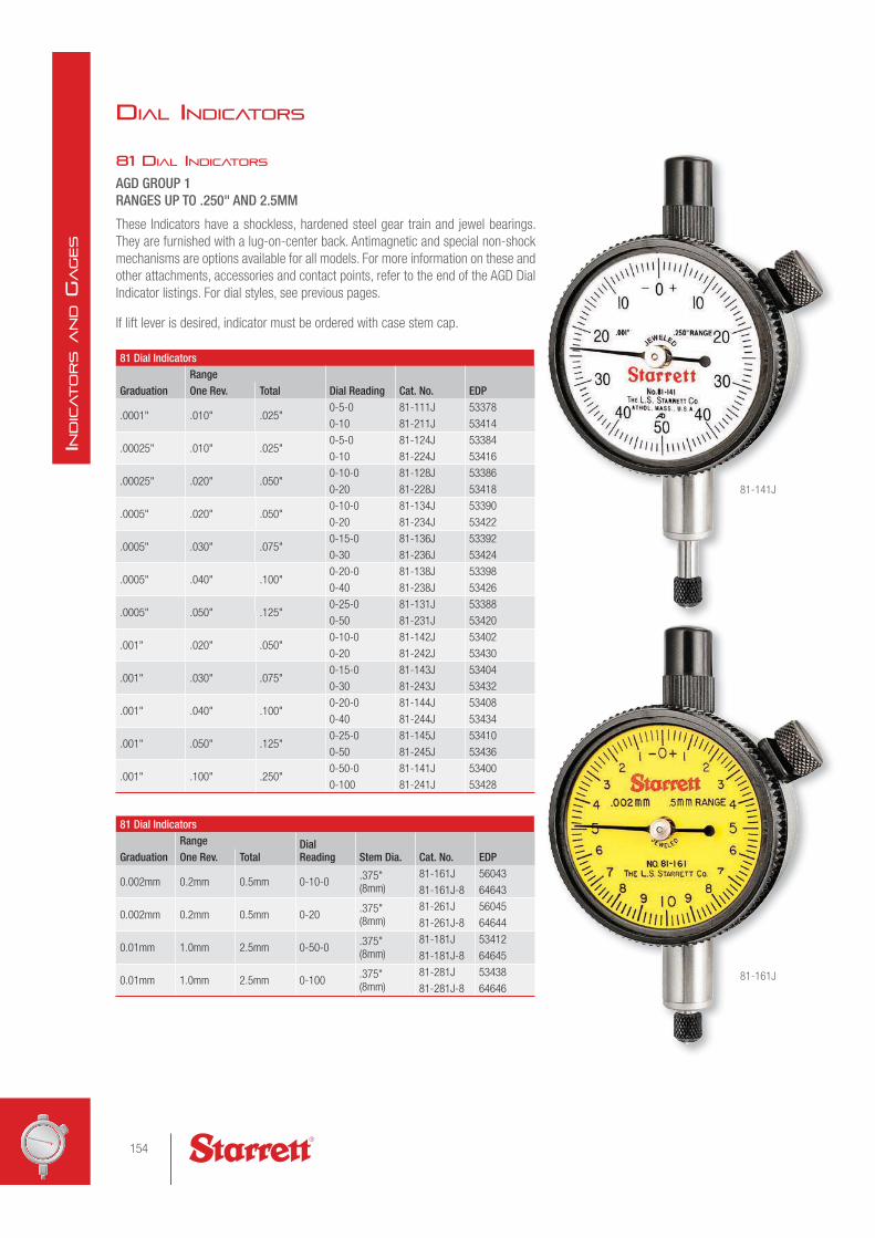
81 DIAL INDICATORS
AGD GROUP 1RANGES UP TO .250" AND 2.5MM
These Indicators have a shockless, hardened steel gear train and jewel bearings.
They are furnished with a lug-on-center back. Antimagnetic and special non-shock
mechanisms are options available for all models. For more information on these and
other attachments, accessories and contact points, refer to the end of the AGD Dial
Indicator listings. For dial styles, see previous pages.
If lift lever is desired, indicator must be ordered with case stem cap.
81 Dial Indicators
GraduationRange
Dial Reading Cat. No. EDPOne Rev. Total
.0001" .010" .025"0-5-0 81-111J 53378
0-10 81-211J 53414
.00025" .010" .025"0-5-0 81-124J 53384
0-10 81-224J 53416
.00025" .020" .050"0-10-0 81-128J 53386
0-20 81-228J 53418
.0005" .020" .050"0-10-0 81-134J 53390
0-20 81-234J 53422
.0005" .030" .075"0-15-0 81-136J 53392
0-30 81-236J 53424
.0005" .040" .100"0-20-0 81-138J 53398
0-40 81-238J 53426
.0005" .050" .125"0-25-0 81-131J 53388
0-50 81-231J 53420
.001" .020" .050"0-10-0 81-142J 53402
0-20 81-242J 53430
.001" .030" .075"0-15-0 81-143J 53404
0-30 81-243J 53432
.001" .040" .100"0-20-0 81-144J 53408
0-40 81-244J 53434
.001" .050" .125"0-25-0 81-145J 53410
0-50 81-245J 53436
.001" .100" .250"0-50-0 81-141J 53400
0-100 81-241J 53428
81 Dial Indicators
GraduationRange Dial
Reading Stem Dia. Cat. No. EDPOne Rev. Total
0.002mm 0.2mm 0.5mm 0-10-0.375" (8mm)
81-161J 56043
81-161J-8 64643
0.002mm 0.2mm 0.5mm 0-20.375" (8mm)
81-261J 56045
81-261J-8 64644
0.01mm 1.0mm 2.5mm 0-50-0.375" (8mm)
81-181J 53412
81-181J-8 64645
0.01mm 1.0mm 2.5mm 0-100.375" (8mm)
81-281J 53438
81-281J-8 64646
81-141J
81-161J
DIAL INDICATORS
154
IND
ICATO
RS A
ND G
AGES

81 DIAL INDICATORS WITH DOUBLE ROW FIGURES
AGD GROUP 1RANGES UP TO .075"
These indicators have the exact same features as our 81 Dial Indicators on the
previous page, except the dials have double-row figures, as illustrated, and they
cannot be specified with a special non-shock mechanism.
If lift lever is desired, indicator must be ordered with case stem cap.
81 Dial Indicators with double row figures
GraduationDialReading
Figures RangeCat. No. EDPDirection Color One Rev. Total
.0001"
+0-10 Clockwise Black
.010" .025"
81-111-624J 53380–0-10 Counter-clockwise Red
+0-10 Counter-clockwise Black81-111-630J 53382
–0-10 Clockwise Red
.0005"
+0-30 Clockwise Black
.030" .075"
81-136-622J 53394–0-30 Counter-clockwise Red
+0-30 Counter-clockwise Black81-136-623J 53396
–0-30 Clockwise Red
.001"
+0-30 Clockwise Black
.030" .075"
81-143-628J 53406–0-30 Counter-clockwise Red
+0-30 Counter-clockwise Black81-143-629J 66666
–0-30 Clockwise Red
Other models with double-row figures can be furnished by request.
81-111-624J
81-111-630J 81-136-623J 81-143-629J
81-111-624J 81-136-622J 81-143-628J
11/32" (8.7)
.375" (9.5)
1-11/16"
(43)
3/4" (19)
7/32" (5)
1/4" (6.4)
1-3/8"
(35)
1-1/2"
(38)
5/8"
(16)
1/4"
(6.3)
1/2" (12.7)
Free drafting template available for this size.
Write The L. S. Starrett Co. at:
121 Crescent Street
Athol, MA 01331.
DIAL INDICATORS
155Check out our website for interactive features at starrett.com
IND
ICATO
RS A
ND G
AGES

25 DIAL INDICATORS
AGD GROUP 2RANGES UP TO 1" AND 25MM
These indicators have a shockless, hardened steel gear train and jewel bearings,
except where noted. They are furnished with a lug-on-center back. Anti magnetic
mechanism is optional for all models. Special non-shock mechanism is available for
all models except 25-109, 25-209 and 25-116. For more information on these and
other attachments, accessories and contact points, refer to the end of the AGD Dial
Indicator listings. For dial styles, see previous pages.
If lift lever is desired, indicator must be ordered with case stem cap.
25 Dial Indicators with Jewel Bearings
GraduationRange
Dial Reading Stem Dia. Cat. No. EDPOne Rev. Total
0.001mm 0.1mm 0.25mm
0-50-0 .375" (9.5mm)25-151J 67644
25-151J-8 68646
0-100 .375" (9.5mm)25-251J 68118
25-251J-8 68647
0.002mm 0.2mm 0.5mm
0-10-0 .375" (9.5mm)25-161J 53250
25-161J-8 64651
0-20 .375" (9.5mm)25-261J 53281
25-261J-8 64652
0.005mm 0.5mm 1.25mm 0-25-0 .375" 25-171J 68643
0.01mm 1.0mm 2.5mm
0-50-0 .375" (9.5mm)25-181J 53252
25-181J-8 64653
0-100 .375" (9.5mm)25-281J 53283
25-281J-8 64654
0.01mm 1.0mm 10mm
0-50-0 .375" (9.5mm)25-381J 53289
25-381J-8 64655
0-100 .375" (9.5mm)25-481J 53297
25-481J-8 64656
0.01mm 1.0mm 25mm
0-50-0 .375" (9.5mm)25-781J 53305
25-781J-8 64657
0-100 .375" (9.5mm)25-881J 53307
25-881J-8 64658
25-111J
25-161J
25-441J
with top lift
DIAL INDICATORS
2-1/4" (57)
11/32" (8.7)
.375" (9.5)
1/4" (6.4)
2-1/16" (52)
23/32" (18)
1-3/4" (44)
3/4" (19)
1/4" (6.3)
15/32" (12)
Free drafting template available for this size.
Write The L. S. Starrett Co. at:
121 Crescent Street
Athol, MA 01331. 656-129J
case stem cap design required
for use with lift lever
see page 170
156
IND
ICATO
RS A
ND G
AGES

25 Dial Indicators with Jewel Bearings
GraduationRange
Dial Reading Cat. No. EDPOne Rev. Total
.00005" .006" .015"0-3-0 25-109J 53222
0-6 25-209J 53254
.0001" .006" .015" 0-3-0 25-116J 53225
.0001" .008" .020"0-4-0 25-118J 53226
0-8 25-218J 53257
.0001" .010" .025"0-5-0 25-111J 53223
0-10 25-211J 53255
.0001" .010" .200"0-5-0 25-511J 53299
0-10 25-611J 53301
.00025" .010" .025"0-5-0 25-124J 53228
0-10 25-224J 53259
.00025" .020" .050"0-10-0 25-128J 53230
0-20 25-228J 53261
.0005" .020" .050"0-10-0 25-134J 53234
0-20 25-234J 53265
.0005" .030 .075"0-15-0 25-136J 53236
0-30 25-236J 53267
.0005" .040" .100"0-20-0 25-138J 53238
0-40 25-238J 53269
.0005" .050" .125" 0-25-0 25-131J 53232
.0005" .050"
.125"
0-50
25-231J 53263
.500" 25-431J 53292
1.000" 25-631J 53304
.001" .020" .050"0-10-0 25-142J 53242
0-20 25-242J 53273
.001" .030" .075"0-15-0 25-143J 53244
0-30 25-243J 53275
.001" .040" .100"0-20-0 25-144J 53246
0-40 25-244J 53277
.001" .050" .125"0-25-0 25-145J 53248
0-50 25-245J 53279
.001" .100" .250"0-50-0 25-141J 53240
0-100 25-241J 53271
.001" .100" .500" 0-50-0 25-341/5J 53285
.001" .100" .500" 0-10025-441/5J 53293
25-441/5J W/SLC* 66864
.001" .100" 1.000" 0-50-0 25-341J 53287
.001" .100" 1.000" 0-10025-441J 53295
25-441/J W/SLC* 66863
25 Dial Indicators Inch Reading Models with Plain Bearings
.001" .100" .500"0-50-0 25-341/5P 53286
0-100 25-441/5P 53294
.001" .100" 1.000"0-50-0 25-341P 53288
0-100 25-441P 53296
* Includes redemption card for Standard Letter of Certification.
253 DIAL INDICATOR SETS
INCH AND MILLIMETER READING
These sets provide in one handy, compact kit three
25 Dial Indicators to handle most gaging jobs at a
minimum cost. Sets are ideal for tool and die shops,
machine shops and toolrooms having occasional work
where a heavy investment in dial indicators would not
be practical. The indicators are furnished with jewel
bearings.
253 Dial Indicator SetsDescription Cat. No. EDPSet of 3 Inch Reading Dial Indicators:25-111J, 25-131J and 25-441J
S253Z 51218
Set of 3 Millimeter Reading Dial Indicators:25-161J, 25-181J and 25-881J
S253MZ 56283
Sets furnished in attractive, protective case.
DIAL INDICATORS
157Check out our website for interactive features at starrett.com
IND
ICATO
RS A
ND G
AGES
t kit th

655 DIAL INDICATORS
AGD GROUP 3RANGES UP TO 1" AND 25MM
These indicators have a shockless, hardened steel gear train and jewel bearings.
They are furnished with a lug-on-center back. Antimagnetic and special non-
shock mechanisms are options available for all models. For more information on
these and other attachments, accessories and contact points, refer to the end of
the AGD Dial Indicator listings. For dial styles, see previous pages.
If lift lever is desired, indicator must be ordered with case stem cap.
655-111J
655-131J
with top lift
655-341J
with stem cap
655-161J-8
655 Dial Indicators
GraduationRange
Dial Reading Stem Dia. Cat. No. EDPOne Rev. Total
0.002mm 0.2mm 0.5mm 0-10-0.375" (9.5mm)
655-161J 53533
655-161J-8 64659
0.002mm 0.2mm 0.5mm 0-20.375" (9.5mm)
655-261J 53603
655-261J-8 64660
0.01mm 1.0mm 2.5mm 0-50-0.375" (9.5mm)
655-181J 53535
655-181J-8 64661
0.01mm 1.0mm 2.5mm 0-100.375" (9.5mm)
655-281J 53605
655-281J-8 64868
0.01mm 1.0mm 25mm 0-100.375" (9.5mm)
655-881J 56229
655-881J-8 64869
11/32"
(8.7)
3/8"
(9.5)
2-3/4"
(69.9)
1/4"
(6.4)
3/4"
(19)
5/8"
(16)1-7/8"
(47.6)
2-1/2"
(63.5)
1/4"
(6.3)
7/16"
(11)
DIAL INDICATORS
655 Dial Indicators
GraduationRange Dial
Reading Cat. No. EDPOne Rev. Total.0001" .008" .020" 0-4-0 655-118J 53507
.0001" .010" .025"0-5-0 655-111J 53505
0-10 655-211J 53537
.0001" .010" .200"0-5-0 655-511J 53615
0-10 655-611J 53617
.00025" .010" .025"0-5-0 655-124J 53509
0-10 655-224J 53539
.00025" .020" .050"0-10-0 655-128J 53511
0-20 655-228J 53541
.00025" .030" .075"0-15-0 655-129J 53513
0-30 655-229J 53543
.0005" .020" .050"0-10-0 655-134J 53517
0-20 655-234J 53587
.0005" .030" .075"0-15-0 655-136J 53519
0-30 655-236J 53589
.0005" .040" .100"0-20-0 655-138J 53521
0-40 655-238J 53591
.0005" .050" .125"0-25-0 655-131J 53515
0-50 655-231J 53585
.001" .020" .050"0-10-0 655-142J 53525
0-20 655-242J 53595
.001" .030" .075"0-15-0 655-143J 53527
0-30 655-243J 53597
.001" .040" .100"0-20-0 655-144J 53529
0-40 655-244J 53599
.001" .050" .125"0-25-0 655-145J 53531
0-50 655-245J 53601
.001" .100" .250"0-50-0 655-141J 53523
0-100 655-241J 53593
.001" .100" .500"0-50-0 655-341/5J 53607
0-100 655-441/5J 53611
.001" .100" 1.000"0-50-0 655-341J 53609
0-100 655-441J 53613
158
IND
ICATO
RS A
ND G
AGES

656 DIAL INDICATORS
AGD GROUP 4RANGES UP TO 1" AND 25MM
These indicators have a shockless, hardened steel gear train and jewel bearings.
They are furnished with a lug-on-center back. Antimagnetic mechanism is
optional for all models. Special non-shock mechanism is available for all models
except 656-109 and 656-209. For more information on these and other
attachments, accessories and contact points, refer to the end of the AGD Dial
Indicator listings. For dial styles, see previous pages.
If lift lever is desired, indicator must be ordered with case stem cap.
656 Dial Indicators
GraduationRange Dial
ReadingStemDia. Cat. No. EDPOne Rev. Total
0.002mm 0.2mm 0.5mm 0-10-0.375" (9.5mm)
656-161J 53690
656-161J-8 64870
0.002mm 0.2mm 0.5mm 0-20.375" (9.5mm)
656-261J 53779
656-261J-8 64871
0.01mm 1.0mm 2.5mm 0-50-0.375" (9.5mm)
656-181J 53692
656-181J-8 64872
0.01mm 1.0mm 2.5mm 0-100.375" (9.5mm)
656-281J 53781
656-281J-8 64873
0.01mm 1.0mm 25mm 0-100.375" (9.5mm)
656-881J 56234
656-881J-8 64874
656 Dial Indicators
GraduationRange Dial
Reading Cat. No. EDPOne Rev. Total
.00005" .006" .015"0-3-0 656-109J 53661
0-6 656-209J 53694
.0001" .008" .020" 0-4-0 656-118J 53664
.0001" .010" .025"0-5-0 656-111J 53662
0-10 656-211J 53695
.0001" .010" .200"0-5-0 656-511J 53791
0-10 656-611J 53795
.0001" .020" .400"0-10-0 656-517J 53793
0-20 656-617J 53797
.00025" .010" .025"0-5-0 656-124J 53666
0-10 656-224J 53697
.00025" .020" .050"0-10-0 656-128J 53668
0-20 656-228J 53699
.00025" .030" .075"0-15-0 656-129J 53670
0-30 656-229J 53701
.0005" .020" .050"0-10-0 656-134J 53674
0-20 656-234J 53705
.0005" .030" .075"0-15-0 656-136J 53676
0-30 656-236J 53707
.0005" .040" .100"0-20-0 656-138J 53678
0-40 656-238J 53709
.0005" .050" .125"0-25-0 656-131J 53672
0-50 656-231J 53703
.001" .020" .050"0-10-0 656-142J 53682
0-20 656-242J 53713
.001" .030" .075"0-15-0 656-143J 53684
0-30 656-243J 53715
.001" .040" .100"0-20-0 656-144J 53686
0-40 656-244J 53717
.001" .050" .125"0-25-0 656-145J 53688
0-50 656-245J 53719
.001" .100" .250"0-50-0 656-141J 53680
0-100 656-241J 53711
.001" .100" .500"0-50-0 656-341/5J 53783
0-100 656-441/5J 53787
.001" .100" 1.000"0-50-0 656-341J 53785
0-100 656-441J 53789
656-111J
656-161J-8
656-129J
stem cap required for
use with lift lever
see page 170
656-441J
with top lift
11/32"
(8.7)
.375"
(9.5)
3-5/8"
(92)
1/4"
(6.4)
3/4"
(19) 5/8"
(16)
2-5/16"
(59)
3-3/8"
(86)
1/4"
(6.4)
27/64"
(11)
Free drafting template available for this size.
Write The L. S. Starrett Co. at:
121 Crescent Street
Athol, MA 01331.
DIAL INDICATORS
159Check out our website for interactive features at starrett.com
IND
ICATO
RS A
ND G
AGES

25, 655, 656 DIAL INDICATORS WITH LONG RANGE
2-5" RANGES
These indicators have a shockless, hardened steel gear train and are furnished
with jewel bearings and lug-on-center backs unless otherwise ordered.
• Conforms to AGD specifications except for range
• Stem cap supplied as standard – top lift available when specified
• Furnished with continuous reading double dial with direct reading count
hands
Approximate DimensionsCat. No. A B C D E F G25-2041J 2-1/4" 2-1/16" 1-13/16" 2-1/16" 3-3/32" 2-7/8" 15/32"
655-2041J 2-3/4" 2-1/2" 1-5/8t" 2-1/16" 3-3/32" 2-7/8" 7/16"
656-2041J 3-5/8" 3-3/8" 1-1/4" 2-1/16" 3-3/32" 3" 27/64"
25-3041J 2-1/4" 2-1/16" 2-13/16" 3-1/16" 4-9/16" 3-7/8" 15/32"
655-3041J 2-3/4" 2-1/2" 2-5/8" 3-1/16" 4-9/16" 3-7/8" 7/16"
656-3041J 3-5/8" 3-3/8" 2-1/4" 3-1/16" 4-9/16" 4" 27/64"
25-4041J 2-1/4" 2-1/16" 3-13/16" 4-1/16" 6" 4-7/8" 15/32"
655-4041J 2-3/4" 2-1/2" 3-5/8" 4-1/16" 6" 4-7/8" 7/16"
656-4041J 3-5/8" 3-3/8" 3-1/4" 4-1/16" 6" 5" 27/64"
25-5041J 2-1/4" 2-1/16" 4-13/16" 5-1/16" 7-1/4" 5-7/8" 15/32"
655-5041J 2-3/4" 2-1/2" 4-5/8" 5-1/16" 7-1/4" 5-7/8" 7/16"
656-5041J 3-5/8" 3-3/8" 4-1/4" 5-1/16" 7-1/4" 6" 27/64"
25, 655, 656 Dial Indicators with Long Range
Graduation RangeDial Reading
Revs. of Hand
AGD Group
Bezel Diameter Cat. No. EDP
.001" 2.000" 0-100 20
2 2-1/4" 25-2041J 53309
3 2-3/4" 655-2041J 53619
4 3-5/8" 656-2041J 53799
.001" 3.000" 0-100 30
2 2-1/4" 25-3041J 53310
3 2-3/4" 655-3041J 53620
4 3-5/8" 656-3041J 53800
.001" 4.000" 0-100 40
2 2-1/4" 25-4041J 53311
3 2-3/4" 655-4041J 53621
4 3-5/8" 656-4041J 53801
.001" 5.000" 0-100 50
2 2-1/4" 25-5041J 53312
3 2-3/4" 655-5041J 53622
4 3-5/8" 656-5041J 53802
Not available with special non-shock mechanism. For other attachments, accessories and contact points, refer
to the end of the AGD Dial Indicator listings.
25-2041J
3/8"
1/4" 1/4"
3/4"
5/8"
.375"
5/32"
E
C
D
A
G
B
F
DIAL INDICATORS
160
IND
ICATO
RS A
ND G
AGES
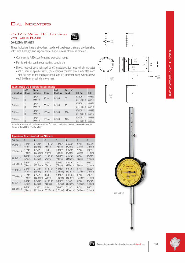
25, 655 METRIC DIAL INDICATORS WITH LONG RANGE
50-125MM RANGES
These indicators have a shockless, hardened steel gear train and are furnished
with jewel bearings and lug-on-center backs unless otherwise ordered.
• Conforms to AGD specifications except for range
• Furnished with continuous reading double dial
• Direct readout accomplished by (1) graduated top tube which indicates
each 10mm of spindle travel, (2) revolution counter which indicates each
1mm full turn of the indicator hand, and (3) indicator hand which shows
each 0.01mm of spindle movement
Approximate Dimensions Inch and Millimeter
Cat. No. A B C D E F G
25-2081J2-1/4" (57mm)
2-1/16" (52mm)
1-13/16" (46mm)
2-1/16" (52mm)
3-3/32" (79mm)
2-7/8" (73mm)
15/32" (12mm)
655-2081J2-3/4" (70mm)
2-1/2" (63.5mm)
1-5/8" (41mm)
2-1/16" (52mm)
3-3/32" (79mm)
2-7/8" (73mm)
7/16" (11mm)
25-3081J2-1/4" (57mm)
2-1/16" (52mm)
2-13/16" (71mm)
3-1/16" (78mm)
4-9/16" (116mm)
3-7/8" (98mm)
15/32" (12mm)
655-3081J2-3/4" (70mm)
2-1/2" (63.5mm)
2-5/8" (67mm)
3-1/16" (78mm)
4-9/16" (116mm)
3-7/8" (98mm)
7/16" (11mm)
25-4081J2-1/4" (57mm)
2-1/16" (52mm)
3-13/16" (81mm)
4-1/16" (103mm)
5-61/64" (151mm)
4-7/8" (124mm)
15/32" (12mm)
655-4081J2-3/4" (70mm)
2-1/2" (63.5mm)
3-5/8" (92mm)
4-1/16" (103mm)
5-61/64" (151mm)
4-7/8" (124mm)
7/16" (11mm)
25-5081J2-1/4" (57mm)
2-1/16" (52mm)
4-13/16" (122mm)
5-1/16" (129mm)
7-1/4" (184mm)
5-7/8" (149mm)
15/32" (12mm)
655-5081J2-3/4" (70mm)
2-1/2" (63.5mm)
4-5/8" (117.5mm)
5-1/16" (129mm)
7-1/4" (184mm)
5-7/8" (149mm)
7/16" (11mm)
25, 655 Metric Dial Indicators with Long Range
GraduationAGD Group
Stem Diameter Range
Dial Reading
Revs. of Hand Cat. No. EDP
0.01mm2 .375"
(9.5mm)50mm 0-100 50
25-2081J 56225
3 655-2081J 56230
0.01mm2 .375"
(9.5mm)75mm 0-100 75
25-3081J 56226
3 655-3081J 56231
0.01mm2 .375"
(9.5mm)100mm 0-100 100
25-4081J 56227
3 655-4081J 56232
0.01mm2 .375"
(9.5mm)125mm 0-100 125
25-5081J 56228
3 655-5081J 56233
Not available with special non-shock mechanism. For contact points, attachments and accessories, refer to
the end of the AGD Dial Indicator listings.
3/8"
(9.5)
1/4"
(6.4)
1/4"
(6.4)
3/4"
(19)
5/32"
(4)
E
C
D
A
G
B
F
.375"
(9.5)
655-2081J
DIAL INDICATORS
161Check out our website for interactive features at starrett.com
IND
ICATO
RS A
ND G
AGES
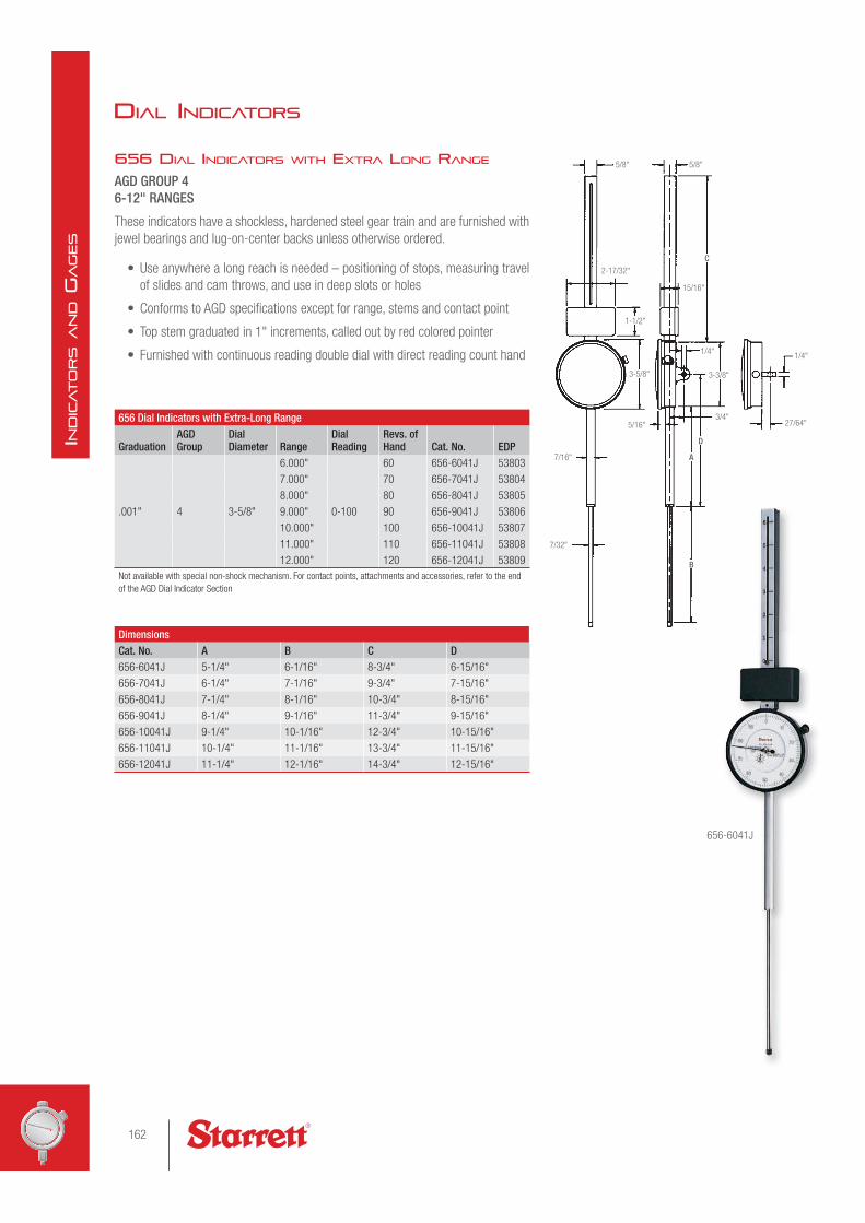
656 DIAL INDICATORS WITH EXTRA LONG RANGE
AGD GROUP 46-12" RANGES
These indicators have a shockless, hardened steel gear train and are furnished with
jewel bearings and lug-on-center backs unless otherwise ordered.
• Use anywhere a long reach is needed – positioning of stops, measuring travel
of slides and cam throws, and use in deep slots or holes
• Conforms to AGD specifications except for range, stems and contact point
• Top stem graduated in 1" increments, called out by red colored pointer
• Furnished with continuous reading double dial with direct reading count hand
656 Dial Indicators with Extra-Long Range
GraduationAGD Group
Dial Diameter Range
Dial Reading
Revs. of Hand Cat. No. EDP
.001" 4 3-5/8"
6.000"
0-100
60 656-6041J 53803
7.000" 70 656-7041J 53804
8.000" 80 656-8041J 53805
9.000" 90 656-9041J 53806
10.000" 100 656-10041J 53807
11.000" 110 656-11041J 53808
12.000" 120 656-12041J 53809
Not available with special non-shock mechanism. For contact points, attachments and accessories, refer to the end
of the AGD Dial Indicator Section
DimensionsCat. No. A B C D656-6041J 5-1/4" 6-1/16" 8-3/4" 6-15/16"
656-7041J 6-1/4" 7-1/16" 9-3/4" 7-15/16"
656-8041J 7-1/4" 8-1/16" 10-3/4" 8-15/16"
656-9041J 8-1/4" 9-1/16" 11-3/4" 9-15/16"
656-10041J 9-1/4" 10-1/16" 12-3/4" 10-15/16"
656-11041J 10-1/4" 11-1/16" 13-3/4" 11-15/16"
656-12041J 11-1/4" 12-1/16" 14-3/4" 12-15/16"
5/8"
7/16"
5/16"
7/32"
2-17/32"
5/8"
1-1/2"
1/4"1/4"
27/64"3/4"
C
D
B
A
3-5/8" 3-3/8"
15/16"
656-6041J
DIAL INDICATORS
162
IND
ICATO
RS A
ND G
AGES

AGD Dial Indicator Backs
TypeFits Starrett Indicator Models Part No. EDP
DimensionsA B C D
Inch mm Inch mm Inch mm Inch mm
*Lug-On-Center
81 PT06836-1 70856
5/8" 16mm 1/4" 6.3mm 1/4" 6.3mm
1/2" 12.7mm
25, 2600 PT07206-1 70960 15/32" 12mm
655 PT06966-1 70888 7/16" 11mm
656 PT07317-1 70980 27/64" 10.7mm
**Lug-Off-Center
81 PT06836 70855
5/8" 16mm 1/4" 6.3mm 1/4" 6.3mm
1/2" 12.7mm
25, 2600 PT06608-1 70770 15/32" 12mm
655 PT06966A 71996 7/16" 11mm
656 PT07317A 71997 27/64" 10.7mm
†Adjustable Bracket (#1/4-20 Thread)
81 PT06836M 70859
1/4" 6.3mm
7/8" 22mm
1/8" 3mm 1/2" 12.7mm25, 2600 PT06608M 70776
1-1/4" 32 mm655 PT06878M 70874
656 PT06903M 70882
†Screw-Type Lug (#1/4-20 Thread)
81 PT24074 72482
1/2" 12.7mm 5/8" 16mm25, 2600 PT24076 72483
655 PT24078 72484
656 PT24080 72485
†Screw-Type Lug (#3/8-24 Thread)
81 PT06836S 72223
1/2" 12.7mm 5/8" 16mm25, 2600 PT06608E 70772
655 PT06878E 72224
656 PT06903E 72225
†Screw-Type Lug (#1/4-28 Thread)
81 PT24073 72486
1/2" 12.7mm 5/8" 16mm25, 2600 PT24075 72487
655 PT24077 72488
656 PT24079 72489
†Post-Type Lug
81 PT06836F 70857
1-1/4" 32mm 1/2" 12.7mm25, 2600 PT06608F 70773
655 PT06878F 71992
656 PT06903F 71994
**Flat
81 PT06836J 70858
25, 2600 PT06608J 70774
655 PT06878J 70873
656 PT06903J 71995
Flat (Plastic)81 PT24921 67295
25, 2600 PT26160 67405
* Regularly furnished on all listed indicators at no extra charge.
** When specified, available on all listed indicators at no extra charge.
† When specified, available at extra charge on all listed indicators. Backs for special requirements are also available; priced on application.
B
D
A
C
B
D
AC
DB
A
C
BA
B
A
Lug-On-Center Lug-Off-Center Adjustable Bracket Screw-Type Lug Post-Type Lug Flat
INDICATOR BACKS
163Check out our website for interactive features at starrett.com
IND
ICATO
RS A
ND G
AGES

647 AND 647M DIAL COMPARATOR INDICATORS
The 647 Dial Comparator Indicators offer a high degree of security and precision.
They are based on a solid and well thought-out construction taking into account the
latest technology. They are manufactured by the most up-to-date methods.
FEATURES AND SPECIFICATIONS
647 and 647M Dial Comparator Indicators
Cat. No. EDP Range Graduation Dial Reading647 00001 .004" .00005" 20-0-20
647M 00002 0.1mm 0.001mm 50-0-50
647 and 647M Dial Comparator Indicator AccessoriesPart No. EDP DescriptionPT15052 00537 Lug-on-center back
PT15053 00538 Lift cable
647
647M
• Effective non-shock mechanism
• Pinions and shafts of the movement are jeweled
• After removal of the safety cap and adjustment
screw on top of the case allows simple and
safe zero setting of the instrument over the total
measuring range
• A safety cap prevents unintentional turning of the
fine adjustment screws
• Stem and spindle are made of hardened stainless
steel
• The measuring spindles are very sensitive on
account of their accurate guides
• Additional overtravel assists with the insertion of
work pieces into the measuring device
• The clear scale is shadow free
• The red tolerance markers are easy to recognize
and to set
• Furnish with flat back
DIAL INDICATORS
164
IND
ICATO
RS A
ND G
AGES
NEW!

676 Magnetic BacksFits Starrett Models Cat. No. EDP81 676-1 56647
25, 2600, 2900 676-2 56648
655 676-3 56649
656 676-4 56650
672 Universal BacksFits Starrett Models Cat. No. EDP25, 2600, 2900 672-2 52887
655 672-3 52888
656 672-4 52889
1/64" (1.6)
27/64" (12)1-7/8"
(47.6)
5/16"-24
6-7/8" (175)
1/4" (6.4)
5-3/4" (146.0)
.375" (9.5)
45º
BENDCLAMPING
SCREW
BACK PLATE
15/16"
(23.8)
9/32 x 13/32"
C'BORE (2)
1-9/16"
(39.7)
5/8"
±.005
(15.9)
9/16" (14.3)TRAVEL
Plus Range
9/16" (14.3)
35/64"
(14)
7/8"
(22)
1-5/8"
(41)
1.000" ±.005
(25)
2.000"
(50.8)
SPECIAL INDICATOR BACKS
674 BACKS WITH ADJUSTABLE MOUNTING BRACKET
For use with gages and gaging fixtures where an adjustable indicator mounting is required. A
dovetail with rack and pinion adjustment provides 1-1/8" (28mm) indicator travel. A 1/8" hex
wrench is used to adjust and lock the indicator in final position. The bracket has two counter-
bored mounting holes (for 1/4" socket head screws), and the back has four screw holes so the
indicator back can be rotated.
672 UNIVERSAL BACKS
Featuring a universal ball joint attached to the end of a gooseneck
shank, these attachments make it possible to position an AGD
indicator at any desired setting. The indicator can be rotated 360º and
angularly up to 90º and locked in the desired position by tightening a
single knurled nut. Straight shank is 3/8" (9.5mm) in diameter.
INDICATOR BACKS
674 Backs with Adjustable Mounting BracketFits Starrett Models Cat. No. EDP81 674-1 66374
25, 2600, 2900 674-2 52892
655 674-3 52893
656 674-4 52894
676 MAGNETIC BACKS
These magnetic backs provide a quick and easy means of attaching
any Starrett AGD indicator to flat, ferrous metal surfaces. A real
time-saver for machine, jig and fixture set up. Requires no clamps,
rods or snugs. A special 5/16"-24 threaded stud back is provided
to replace the standard lug back. The powerful, permanent magnet
is then attached to the threaded stud. Anti-magnetic indicators are
not required.
165Check out our website for interactive features at starrett.com
IND
ICATO
RS A
ND G
AGES

INDICATOR ACCESSORIES
SPECIAL NON-SHOCK MECHANISM
Starrett dial indicators have hardened, stainless steel gears, pinions and racks
for maximum resistance to shock. Where the rack is subject to repeated, severe
and/or excessive mechanical shocks, many Starrett AGD dial indicators may be
ordered with a special non-shock mechanism. Based on a positive-loaded, split
gear assembly, this simple device protects indicator accuracy, prolongs life, and
reduces service costs.
When ordering, specify "N/S" after the dial indicator catalog number.
The following indicators are not available with non-shock mechanism: 25-109, 25-
209, 2600 and 2700 Indicators; 656-109, 656-209 and all other indicators with 2"
(50mm) range and above.
671 Universal AttachmentRange (Approx.) Cat. No. EDP1/8" (3mm) 671 52886
670 Indicator Hole AttachmentRange (Approx.) For Hole Depths to:
Cat. No. EDPInch mm Inch mm3/8" 9.5mm 13/16" 20mm 670A 52884
9/16" 14mm 1-11/16" 42mm 670B 52724
25-111J
with Special Non-Shock Mechanism
AGD INDICATOR ATTACHMENTS AND ACCESSORIES
670 INDICATOR HOLE ATTACHMENT
These hole attachments make it possible to measure the inside of
holes and other surfaces that cannot be reached with the regular
indicator spindle. Both attachments have a .375" (9.5mm) diameter
hole to fit all indicators made to AGD standards and can be securely
clamped to the indicator stem. The ball end on the swivel arm which
contacts the work is 1/8" (3mm) in diameter.
671 UNIVERSAL ATTACHMENT
This Universal Attachment is for use with indicators having standard
AGD .375" (9.5mm) stem diameters. It clamps on the indicator stem
and its movement is transmitted through the contact point to the
indicator. Furnished with two interchangeable arms, one straight for
measuring internal surfaces and one angular for measuring at right
angles to the indicator spindle.
670A
671
166
IND
ICATO
RS A
ND G
AGES

INDICATOR ACCESSORIES
28 SHOCK ABSORBING ANVIL
Anvil replaces the regular contact point on any AGD
indicator, protecting its movement against mechanical
shock. Any sudden impact telescopes the anvil into the
body of the unit against an internal spring. Acts as a
solid contact point when the indicator is used normally.
Furnished with #4-48 AGD standard screw thread.
Extra-Length Contact Points, Regular StyleLength Rounded End Flat EndInch mm Part No. EDP Part No. EDP
1/4" 6.4mmPT07215 70965
PT10453 72048PT01761 75263
1/2" 13mm PT06677 70823 PT09560 71260
3/4" 19mm PT06677A 70824 PT09560A 71261
1" 25mm PT06677B 70825 PT09560B 71262
1-1/4" 32mm PT06677C 70826 PT09560C 71263
1-1/2" 38mm PT06677D 70827 PT09560D 71264
1-3/4" 44mm PT06677E 70828 PT09560E 71265
2" 50mm PT06677F 70829 PT09560F 71266
2-1/4" 57mm PT06677G 70830 PT09560G 71267
2-1/2" 63mm PT06677H 70831 PT09560H 71268
2-3/4" 70mm PT06677J 70832 PT09560J 71269
3" 75mm PT06677K 70833 PT09560K 71270
4" 100mm PT10459 71327
Shock Absorbing AnvilCat. No. EDP28 50199
20 21
191817
3/8" 1/2"
1"3/4"
1/4"
Flat-End Steel PointsDiameter
Style No. Part No. EDPInch mm1/4" 6.4 17 PT06632-17 70804
3/8" 9.5 18 PT06632-18 70805
1/2" 12.7 19 PT06632-19 70806
3/4" 19 20 PT06632-20 70808
1" 25 21 PT06632-21 70807
AGD INDICATOR CONTACT POINTS AND ACCESSORIES
Any of the contact points listed here can also be used with the 650 and 651
Indicators and with the 196 Indicators by using the 196R Adapter.
EXTRA-LENGTH REGULAR-STYLE CONTACT POINTS WITH ROUND OR FLAT ENDS
1/4-4"/6-100MM
All Starrett AGD indicators are regularly furnished with 1/4" (6.4mm) length
interchangeable contact points. Available in standard lengths to 4" (100mm).
Diameter is 13/64" (5mm), with a #4-48 screw thread. Made from high grade
steel, hardened and ground. Other lengths are also available priced on application.
Available with round or flat ends as listed.
REGULAR-STYLE CARBIDE CONTACT POINTS WITH ROUND OR FLAT END
Two round points are available in standard lengths. 1/4" (6.3mm), PT08399-X (EDP
66053) – or – 1/2" (13mm), PT06677-X (EDP 66054). One flat point is available
in standard length; 1/4" (6.3mm), PT10453-X (EDP 66068). Interchangeable points
have a #4-48 screw thread. Longer lengths can be easily obtained by adding contact
point extensions (see next page). Other sizes also available by request.
FLAT-END STEEL POINTS
The flat-end contact points have hardened steel
contact surfaces, ground flat and lapped. They are
furnished with a #4-48 screw thread for use on any
AGD Indicator.
167Check out our website for interactive features at starrett.com
IND
ICATO
RS A
ND G
AGES

3/8" (9.5)
3/8"
(9.5)
3/8" (9.5)
1/2"
(13)
1/8"
(3)
1/2"
(13) 3/8"
(9.5)
3/32"
(2.4)
1/2" (13)
1/4" (6.3)
1/16"
(1.6)
5/8" (16)
1/32"
(0.8)5/32"
(4)
9/32" (7)
7/16"
(11)
1/16"
(1.6)
1"
(25)
1/16"
(1.6) 1/16"
(1.6)
1-7/16"
(36.5) 2"
(50)
1/16"
(1.6)
1/16"
(1.6)
3/16"
(4.7) 9/16" (14)3/8"
1/8"
25R CONTACT POINT SET
14 points with #4-48 screw thread to fit AGD indicators: a regular
1/4" (6.3mm) long point; 9 special form points; a 28 Shock Absorbing
Anvil; and 3 extra long points 1/2", 3/4" and 1" (13, 19, 25mm) long.
High grade steel, hardened and ground. All points are mounted on a
convenient aluminum ring for safe keeping and easy selection.
Contact PointsStyle No. Part No. EDP2 PT06632-2 70790
3 PT06632-3 70791
4 PT06632-4 70792
5 PT06632-5 70793
6 PT06632-6 70794
7 PT06632-7 70795
8 PT06632-8 70796
9 PT06632-9 70797
10 PT06632-10 70798
11 PT06632-11 70799
12 PT06632-12 70800
13 PT06632-13 70801
14 PT06632-14 70802
15 PT06632-15 70803
25W 53916
25R 50153
PT24728 64963
PT24729 64964
6
1110987
25W15141312
AGD Contact Point ExtensionsLength Part No. EDP1/2" PT21697-1/2 64632
1" PT21697-1 64633
2" PT21697-2 64634
3" PT21697-3 64635
4" PT21697-4 64636
INDICATOR ACCESSORIES
AGD INDICATOR SPECIAL CONTACT POINTS AND ACCESSORIES
SPECIAL FORM CONTACT POINTS
Starrett Special Contact Points are furnished
in fourteen shapes. Knurled diameter is
approximately 13/64" (5mm). All have #4-48
screw thread and can be used on any AGD
indicator. Other special shapes are available
on special order.
Carbide, sapphire, diamond or teflon-coated
contact points are also available by request.
25W ROLLER CONTACT POINT
This contact has a small, hardened roller
3/8" (9.5mm) in diameter for continuous
gaging of moving material where the material
movement is at a slow speed. Contact has
#4-48 screw thread and substitutes for the
regular contact point provided on Starrett
and other AGD indicators. Furnished with a
knurled check nut for positioning the contact
on the indicator spindle. See drawing (right).
2 3 4 5
28
2
34
10
8
PT06677-B PT06677-A
PT06677
PT01761
9
6
5
7 25R
From Metric Racks to Inch Contacts
PT24728
From Inch Racks to Metric Contacts
PT24729
AGD CONTACT POINT EXTENSIONS
LENGTH
#4-48
Thread#4-48
Thread
AGD CONTACT ADAPTORS
3/8" 9.5 mm
.195-.198"
dia. M 2.5 x .45 Thread #4-48
Thread#4-48
Thread
168
IND
ICATO
RS A
ND G
AGES
INDICATOR ACCESSORIES
25SC SPLIT COLLETS
ENGLISH AND METRIC THREADS
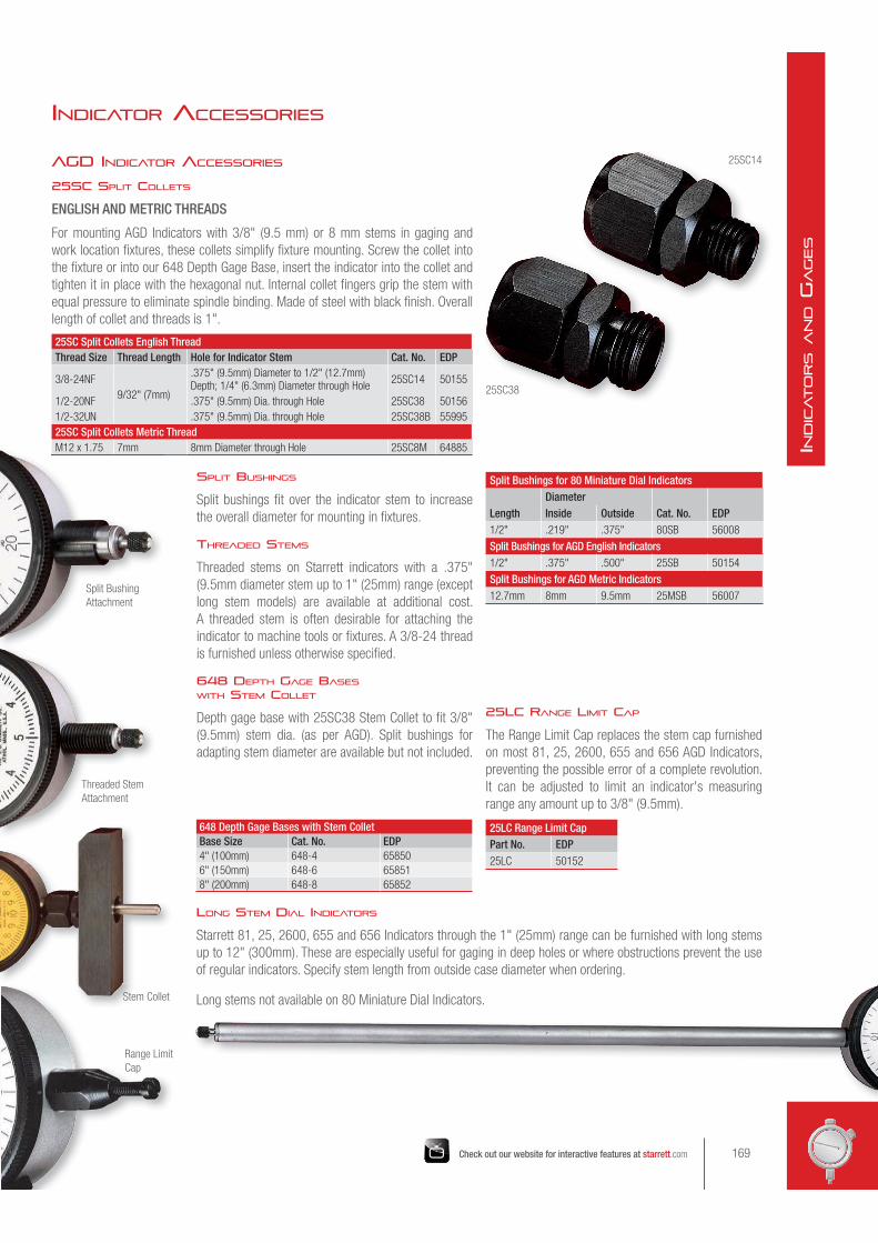
For mounting AGD Indicators with 3/8" (9.5 mm) or 8 mm stems in gaging and
work location fixtures, these collets simplify fixture mounting. Screw the collet into
the fixture or into our 648 Depth Gage Base, insert the indicator into the collet and
tighten it in place with the hexagonal nut. Internal collet fingers grip the stem with
equal pressure to eliminate spindle binding. Made of steel with black finish. Overall
length of collet and threads is 1".
25SC Split Collets English ThreadThread Size Thread Length Hole for Indicator Stem Cat. No. EDP
3/8-24NF
9/32" (7mm)
.375" (9.5mm) Diameter to 1/2" (12.7mm) Depth; 1/4" (6.3mm) Diameter through Hole
25SC14 50155
1/2-20NF .375" (9.5mm) Dia. through Hole 25SC38 50156
1/2-32UN .375" (9.5mm) Dia. through Hole 25SC38B 55995
25SC Split Collets Metric ThreadM12 x 1.75 7mm 8mm Diameter through Hole 25SC8M 64885
Split Bushings for 80 Miniature Dial Indicators
LengthDiameter
Cat. No. EDPInside Outside1/2" .219" .375" 80SB 56008
Split Bushings for AGD English Indicators1/2" .375" .500" 25SB 50154
Split Bushings for AGD Metric Indicators12.7mm 8mm 9.5mm 25MSB 56007
648 Depth Gage Bases with Stem ColletBase Size Cat. No. EDP4" (100mm) 648-4 65850
6" (150mm) 648-6 65851
8" (200mm) 648-8 65852
25LC Range Limit CapPart No. EDP25LC 50152
AGD INDICATOR ACCESSORIES
SPLIT BUSHINGS
Split bushings fit over the indicator stem to increase
the overall diameter for mounting in fixtures.
THREADED STEMS
Threaded stems on Starrett indicators with a .375"
(9.5mm diameter stem up to 1" (25mm) range (except
long stem models) are available at additional cost.
A threaded stem is often desirable for attaching the
indicator to machine tools or fixtures. A 3/8-24 thread
is furnished unless otherwise specified.
648 DEPTH GAGE BASES WITH STEM COLLET
Depth gage base with 25SC38 Stem Collet to fit 3/8"
(9.5mm) stem dia. (as per AGD). Split bushings for
adapting stem diameter are available but not included.
M12 x 1.75 7mm
25SC14
25SC38
25LC RANGE LIMIT CAP
The Range Limit Cap replaces the stem cap furnished
on most 81, 25, 2600, 655 and 656 AGD Indicators,
preventing the possible error of a complete revolution.
It can be adjusted to limit an indicator's measuring
range any amount up to 3/8" (9.5mm).
LONG STEM DIAL INDICATORS
Starrett 81, 25, 2600, 655 and 656 Indicators through the 1" (25mm) range can be furnished with long stems
up to 12" (300mm). These are especially useful for gaging in deep holes or where obstructions prevent the use
of regular indicators. Specify stem length from outside case diameter when ordering.
Long stems not available on 80 Miniature Dial Indicators.
Split Bushing
Attachment
Threaded Stem
Attachment
Stem Collet
Range Limit
Cap
169Check out our website for interactive features at starrett.com
IND
ICATO
RS A
ND G
AGES

INDICATOR ACCESSORIES
AGD INDICATOR ACCESSORIES
TOP LIFT
A knurled grip allows the spindle to be manually lifted and returned by spring action to contact the work. Furnished
in place of the stem cap on .500", 1.000", 10mm and 25mm range indicators. No extra charge on AGD Indicators
up to 1" (25mm) range; over 1" (25mm) range, priced on request. To order, specify "with Top Lift" after the
indicator catalog number.
NOTE: Will not fit on 2700 Indicators.
RUBBER DUST GUARD
Protects the rack of AGD Indicators from foreign matter under adverse gaging conditions. Made in lengths to fit
81, 25, 2600, 655 and 656 Indicators up to 1" (25mm) range.
Rubber Dust GuardIndicator Range Part No. EDP.400", .500", 1.000" (10mm, 12.7mm, 25mm) PT09545 71256
Ranges under .400" (10mm) PT09763 71289
Lever ControlPart No. EDPPT99356 72088
AGD DIAL INDICATOR TOLERANCE HANDS
Starrett dial indicators may be ordered with crystal-mounted or bezel-mounted
tolerance hands for visually checking limits of a given dimension.
Crystal-mounted hands, both colored red, are positioned under the crystal and are
individually adjustable through 360º by turning concentric knurled knobs on the
outside of the crystal. Available for all 81, 25, 655 and 656 AGD Dial Indicators.
Bezel-mounted hands, both colored red, rotate inside the bezel. They are mounted
outside the crystal and are independently adjustable through 360º. Available for 81
and 25 AGD Indicators only.
Snap-on bezel-mounted hands, two hands colored red, are easily mounted on the
outside of the bezel and are adjustable through 360º. Available for 25 AGD Indicators
only. Order PT99513 (EDP 66038).
MAXIMUM HAND
This red-colored hand records the maximum position reached by the indicator hand
within a single revolution. Mounted under the crystal, it has a small nib at its point.
The indicator hand contacts the nib, advancing the maximum hand which remains in
position when the indicator hand returns to its at-rest position. To reset the maximum
hand, turn the knurled knob mounted outside the crystal.
To order Tolerance or Maximum Hands, specify the indicator catalog number
followed by the type of hand desired.
LEVER CONTROL
Handy attachment mounts in place of stem cap and is interchangeable on most
Starrett 81, 25, 2600, 655 and 656 AGD Indicators up to 1" or 25mm range.
Pressing down lever lifts spindle; releasing it lets spindle contact the work. Easy to
install in the left or right hand position using a screwdriver and an open end wrench.
If ordered on a new indicator, specify left or right hand position. (Furnished at left
unless otherwise ordered.)
NOTE: Fits only indicators with a case stem cap.
Top Lift
Dust Guard
Maximum Hand in at-rest position with indicator hand (left), and in
recording position (right).
Indicators with snap-on bezel-mounted hands (left), crystal-mounted
hands (above), and bezel-mounted hands (right).
170
IND
ICATO
RS A
ND G
AGES