DI MILANO CFD Modeling Techniques for the Design of … - Pres_CFD after-treatment... · CFD...
35
POLITECNICO DI MILANO A. Onorati, G. Montenegro, A. Della Torre, L. Nocivelli Internal Combustion Engine Group Department of Energy, Politecnico di Milano CFD Modeling Techniques for the Design of After-Treatment Systems
Transcript of DI MILANO CFD Modeling Techniques for the Design of … - Pres_CFD after-treatment... · CFD...

POLITECNICO
DI MILANO
A. Onorati, G. Montenegro, A. Della Torre, L. Nocivelli
Internal Combustion Engine GroupDepartment of Energy, Politecnico di Milano
CFD Modeling Techniques for the
Design of After-Treatment Systems
POLITECNICO
DI MILANO
Internal combustion engine development will never stop!
Efficiency increase Pollutant emission control
Waste heat
recoveryDownsizing
After-
treatment
Alternative
fuelsDirect
injection
Combustion
systems
Background
POLITECNICO
DI MILANOResearch arguments at PoliMi
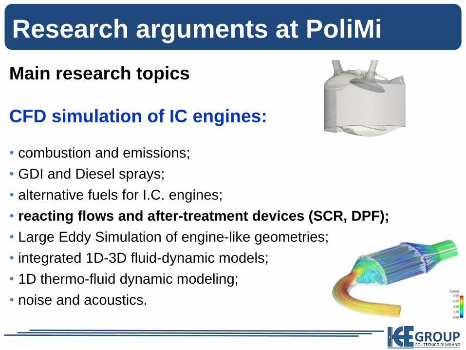
Main research topics
CFD simulation of IC engines:
• combustion and emissions;
• GDI and Diesel sprays;
• alternative fuels for I.C. engines;
• reacting flows and after-treatment devices (SCR, DPF);
• Large Eddy Simulation of engine-like geometries;
• integrated 1D-3D fluid-dynamic models;
• 1D thermo-fluid dynamic modeling;
• noise and acoustics.

POLITECNICO
DI MILANO
CFD code: OpenFOAM/Lib-ICE
• We started to work with OpenFOAM in 2000.
Our group is currently involved in several
activities in Europe, concerning OpenFOAM
development and applications.
• OpenFOAM is a free-to-use Open Source
numerical simulation software with extensive
CFD and multi-physics capabilities, written in a
highly efficient C++ object-oriented programming.
• Free-to-use, allows to exploit high parallelization
with only hardware costs.
• Ideal platform for research collaborations.
• Very wide diffusion with 2000 downloads/week.

POLITECNICO
DI MILANO
CFD code: OpenFOAM/Lib-ICE
Tool:
The ICE group of Politecnico di Milano has
contributed to develop the engine library under
OpenFOAM technology (Lib-ICE):
• Moving mesh algorithms
• Spray modeling
• Combustion process modeling
• DPF and SCR modeling
• 1D-3D coupling interface
• Non-linear acoustics modeling
•in-house CFD libraries and solvers (Lib-ICE)
developed under the OpenFOAM® technology.

POLITECNICO
DI MILANO
GASDYN model: 1D simulation of wave motion andchemical species transport, with reactions in the gas and solidphase. Modeling of the main after-treatment devices: 3W catalyst,DPF, DOC, SCR, deNOx trap, secondary air injection, etc.
Silencers
Exhaust after-treatment system
Air injection system
Combustion
3way CC SCR
DOCDPFTurbocharger
Intake system
NoiseExhaust manifold
1D thermo-fluid dynamic modeling of IC engines

POLITECNICO
DI MILANO1D simulation code: GASDYN
• Developed at PoliMi during
the last 20 years.

POLITECNICO
DI MILANO
mmY ii /
Vector of specie mass fractions
.
Y
Y
1N
1
Y
F
Fe
uF
F
)t,x(0
Y
W
Fu
Fuh
pFFu
uF
)(0
2
Y
WF
0
0dx
dFp
0
)( WB
F
Fqq
GF
re
Y
WC
)(
0
)(
Reactions of species in the flow (exhaust manifold andcatalysts).
Fundamental equations
Fundamental equations in strong conservative form for1D, unsteady, reacting flows in engine ducts:
0
)()(
x
)(
t
)t,x(WCWB
WFW
O2
N2
Ar
CO2
H2O
H2
CO
NO
C3H6
C3H8
.
.
.
Y=

POLITECNICO
DI MILANOSCR, 1D modeling: six cylinder Diesel engine
Urea injector
Hydrolysis SCR

POLITECNICO
DI MILANO
Thermic reactor
Catalytic reactor
SCR modeling: urea injection and reactions
HNCO NH (s) NH-CO-NH 322
“Standard” SCR reactionO6H 4NO 4NO 4NH 2223
Urea thermic
decomposition
4NH3 + 3O2 2N2 + 6H2O8NH3 + 6NO 7N2 + 12H2O4NH3 + 2NO + 2NO2 2N2 + 6H2O “Fast” SCR reaction
Ammonia Oxidation
Isocyanic acid hydrolysis232 CO NHOH HNCO
O xH (s) NH-CO-NH (aq.) NH-CO-NH 22222

POLITECNICO
DI MILANO
Calculated and measured de-NOx efficiency and NO emission level versus catalyst temperature at 2200 rpm.
SCR modeling: urea injection and reactions
0
10
20
30
40
50
60
70
80
90
100
400 450 500 550 600 650
Temperature [k]
DeN
Ox
[%]
Measured
Calculated
0
10
20
30
40
50
60
70
80
90
100
400 450 500 550 600 650
Temperature [k]
DeN
Ox
[%]
Measured
Calculated
0
200
400
600
800
1000
1200
400 450 500 550 600 650
Temperature [k]
NO
[p
pm
]0
200
400
600
800
1000
1200
400 450 500 550 600 650
Temperature [k]
NO
[p
pm
]
NO out, measured
NO out, calculated
NO in, measured
0
10
20
30
40
50
60
70
80
90
100
400 450 500 550 600 650
Temperature [k]
DeN
Ox
[%]
Measured
Calculated
0
10
20
30
40
50
60
70
80
90
100
400 450 500 550 600 650
Temperature [k]
DeN
Ox
[%]
Measured
Calculated
0
200
400
600
800
1000
1200
400 450 500 550 600 650
Temperature [k]
NO
[p
pm
]0
200
400
600
800
1000
1200
400 450 500 550 600 650
Temperature [k]
NO
[p
pm
]
NO out, measured
NO out, calculated
NO in, measured

POLITECNICO
DI MILANO
Pre-Processing In-cylinder flows & combustion After-treatment
Automatic mesh generation
Gas exchange, fuel air mixingSI, CI, PCCI, HCCI combustion
After-treatment modeling
SCR, DPF, TWC, DOC
OpenFOAM at PoliMi (Lib-ICE)
POLITECNICO
DI MILANOSpray and wall-film modeling
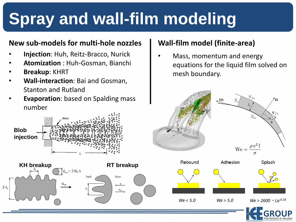
New sub-models for multi-hole nozzles
• Injection: Huh, Reitz-Bracco, Nurick• Atomization : Huh-Gosman, Bianchi• Breakup: KHRT• Wall-interaction: Bai and Gosman,
Stanton and Rutland• Evaporation: based on Spalding mass
number
We > 2600・La-0.18We > 5.0We < 5.0
Wall-film model (finite-area)
• Mass, momentum and energy equations for the liquid film solved on mesh boundary.
RT breakupKH breakup
Blob
injection

POLITECNICO
DI MILANO
Injector 1Injector 2
This work was sponsored and carried out in collaboration with
Full-cycle simulation of GDI engines
GDI engine simulations

POLITECNICO
DI MILANO
• Unsteady flow solver with Lagrangian tracking of particles.
• Multi-component liquid mixture and homogeneous chemical
reactions (urea thermal decomposition).
• Wall film formation and evaporation.
After-treatment: SCR

POLITECNICO
DI MILANOAfter-treatment: SCR
• Unsteady flow solver with Lagrangian tracking of particles.
• Multi-component liquid mixture and homogeneous chemical
reactions (urea thermal decomposition).
• Wall film formation and evaporation.

POLITECNICO
DI MILANO
Urea spray in a duct
• Liquid urea properties have been added in order to account forAdBlue or urea solutions.
• Inclusion of chemistry to model the thermal decomposition of ureaparticles into HNCO and NH3 .
H2O distribution
NH3 distribution

POLITECNICO
DI MILANO
Selective Catalytic Reduction (SCR)The chemical and physical processes to be taken into
account are:
• the injection and evaporation of urea solution;
• the thermal decomposition of urea in gas phase;
• the hydrolysis of isocyanic acid generated during the urea
thermal decomposition process;
• the reactions of NOx reduction (fast and standard) occurring onto
the catalytic bed:

POLITECNICO
DI MILANO
Injection of urea-water solution and solid deposits
Possible solid urea byproduct deposition
Wall impingement can be a paramount parameter to be taken into
account in the generation of an uniformly distributed gaseous
mixture.
Direct injection of urea-water solution
in the pre-catalytic section:
• Low pressure injection.
• No secondary breakup.
• Slow urea thermal decomposition.

POLITECNICO
DI MILANO
• Multi-component liquid mixture customized
properties for urea along with multi-component
liquid film.
• Temperature dependence of the spray-wall
interaction and wall cooling effect.
SCR modeling: injection of AdBlue
Cold wall Hot wall
T* = 0.8 T* = 1.2
Absolute We = 264
Normal We = 137
T* = Twall / Tsat
81
85
LaWeK
(In collaboration with EMPA, Dr. P. Dimopoulos
and Fiat Industrial - CNH)

POLITECNICO
DI MILANO
Film thickness Film temperature
SCR: wall film modeling

POLITECNICO
DI MILANO
After-treatment: open-cell foams
Foam samples
CFD simulation of open-cell foams
(in collaboration with EMPA, Dr. P. Dimopoulos)
POLITECNICO
DI MILANO
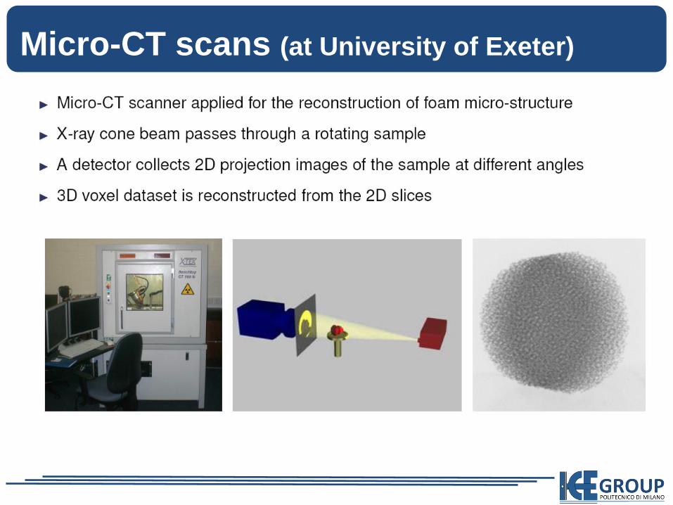
Micro-CT scans (at University of Exeter)

POLITECNICO
DI MILANOMicro-CT: image processing
porosity: 95-97% porosity: 85-90% porosity: 45-55%

POLITECNICO
DI MILANOOpen-cell foams for after-treatment systems
Open-cell foam
Filtering media
Al alloy
95% porosity
40 ppi
SiC
86% porosity
80 ppi
Applications:
Catalytic
substrates for
after-treatment
devices (as an
alternative to
traditional
honeycomb)
Cordierite
50% porosity
16 µm pore
Applications:
Removal of
particulate matter
from exhaust gas

POLITECNICO
DI MILANO
From micro-scale to full scale simulation of
after-treatment systems:
Open-cell foams for after-treatment systems
POLITECNICO
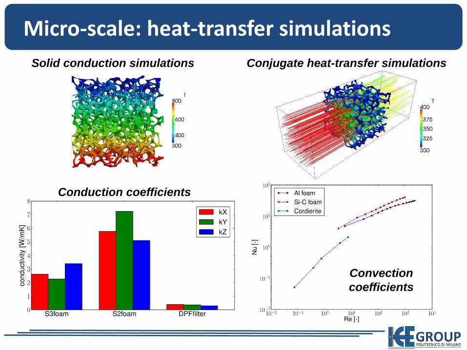
DI MILANOMicro-scale: heat-transfer simulations
Solid conduction simulations Conjugate heat-transfer simulations
Conduction coefficients
Convection
coefficients

POLITECNICO
DI MILANOValidation: Diesel Particulate Filter
EX80-100/17 EX80-200/14
Simulation of flow through a
couple of DPF channels

POLITECNICO
DI MILANOModelling catalytic reactions
gas
near wall
gas
washcoat
solid wall
Mass transfer between
gas phase and washcoat
catalytic surface
A library for the modelling of surface reactions has been
implemented on the basis of the OpenFOAM code.
Reaction heat is released and
transferred to fluid and solid
phase

POLITECNICO
DI MILANOReacting flow simulation
Al foam 95% porosity – 40 ppi / Micro-CT reconstruction
• Surface reaction on washcoat
region
• Infinitely fast reaction model
• Conjugate heat transfer
• Fluid: inlet T=300K
• Solid: fixed T=300K on the inlet
side, adiabatic elsewhere.
CH4 + O2 → CO2 + H2O

POLITECNICO
DI MILANOReacting flow simulation
Al foam 95% porosity – 40 ppi / Micro-CT reconstruction

POLITECNICO
DI MILANOApplication example: TWC
CO oxidation
CO+0.5O2 -> CO2
H2 oxidation
H2+0.5O2 -> H2O
HC oxidation
C3H6 + 3O2 -> 3CO2 + 6H2O
NOx reduction
CO+NO -> CO2+0.5N2
H2+NO -> H2O + 0.5N2
Steam water reforming
CO+H2O -> CO2 + H2
C3H6 + 3H2O -> 3CO2 + 6H2

POLITECNICO
DI MILANO
CFD models (both 1D and 3D) represent robust tools to investigate the behavior of after-treatment systems and help the design for maximum conversion efficiency.
Our experience is focused on self-developed libraries in GASDYN (1D) and OpenFOAM (LibICE).
Conclusions

POLITECNICO
DI MILANO
New solutions for catalytic substrates, based on open-cell foams, will be studied, to achieve a general improvement of performances (pressure loss, warm-up, precious metal loading…).
Conclusions

POLITECNICO
DI MILANO
Thanks for your attention!
Questions?
Conclusions