DI-4108 and DI-4208 USB DAQ Hardware Manual...DI-4108 and DI-4208 Hardware Manual Introduction 2...
40
The way PC-based instrumentation should be DI-4108 and DI-4208 8-Channel High Speed Data Acquisition Systems with Programmable Gain, Expandability with ChannelStretch™, and Stand-alone Capability User's Manual Manual Revision E Copyright © 2019 by DATAQ Instruments, Inc. The Information contained herein is the exclusive property of DATAQ Instruments, Inc., except as otherwise indicated and shall not be reproduced, transmitted, transcribed, stored in a retrieval system, or translated into any human or computer language, in any form or by any means, electronic, mechanical, magnetic, optical, chemical, manual, or otherwise without expressed written authorization from the com- pany. The distribution of this material outside the company may occur only as authorized by the company in writing. DATAQ Instruments' hardware and software products are not designed to be used in the diagnosis and treatment of humans, nor are they to be used as critical components in any life-support systems whose failure to perform can rea- sonably be expected to cause significant injury to humans. DATAQ, the DATAQ logo, and WINDAQ are registered trademarks of DATAQ Instruments, Inc. All rights reserved. DATAQ Instruments, Inc. 241 Springside Drive Akron, Ohio 44333 U.S.A. Telephone: 330-668-1444 Fax: 330-666-5434 Designed and manufactured in the United States of America
Transcript of DI-4108 and DI-4208 USB DAQ Hardware Manual...DI-4108 and DI-4208 Hardware Manual Introduction 2...

T h e w a y P C - b a s e d i n s t r u m e n t a t i o n s h o u l d b e
DI-4108 and DI-42088-Channel High Speed Data Acquisition Systems with Programmable Gain,
Expandability with ChannelStretch™, and Stand-alone Capability
User's ManualManual Revision E
Copyright © 2019 by DATAQ Instruments, Inc. The Information contained herein is the exclusive property of DATAQ Instruments, Inc., except as otherwise indicated and shall not be reproduced, transmitted, transcribed, stored in a retrieval system, or translated into any human or computer language, in any form or by any means, electronic, mechanical, magnetic, optical, chemical, manual, or otherwise without expressed written authorization from the com-pany. The distribution of this material outside the company may occur only as authorized by the company in writing.
DATAQ Instruments' hardware and software products are not designed to be used in the diagnosis and treatment of humans, nor are they to be used as critical components in any life-support systems whose failure to perform can rea-sonably be expected to cause significant injury to humans.
DATAQ, the DATAQ logo, and WINDAQ are registered trademarks of DATAQ Instruments, Inc. All rights reserved.
DATAQ Instruments, Inc.241 Springside Drive
Akron, Ohio 44333 U.S.A.Telephone: 330-668-1444
Fax: 330-666-5434Designed and manufactured in the
United States of America

Warranty and Service PolicyProduct WarrantyDATAQ Instruments, Inc. warrants that this hardware will be free from defects in materials and workmanship under normal use and service for a period of 1 year from the date of shipment. DATAQ Instruments' obligations under this warranty shall not arise until the defective material is shipped freight prepaid to DATAQ Instruments. The only responsibility of DATAQ Instruments under this warranty is to repair or replace, at its discretion and on a free of charge basis, the defective material.
This warranty does not extend to products that have been repaired or altered by persons other than DATAQ Instru-ments employees, or products that have been subjected to misuse, neglect, improper installation, or accident.
DATAQ Instruments shall have no liability for incidental or consequential damages of any kind arising out of the sale, installation, or use of its products.
Service Policy
1. All products returned to DATAQ Instruments for service, regardless of warranty status, must be on a freight-pre-paid basis.
2. DATAQ Instruments will repair or replace any defective product within 5 days of its receipt.
3. For in-warranty repairs, DATAQ Instruments will return repaired items to the buyer freight prepaid. Out of war-ranty repairs will be returned with freight prepaid and added to the service invoice.
iii

DI-4108 and DI-4208 Hardware Manual
Table of ContentsWarranty and Service Policy ................................................................................................................ iii1. Introduction ........................................................................................................................................ 1
Features .............................................................................................................................................. 1Analog Inputs .................................................................................................................................... 1Digital I/O .......................................................................................................................................... 2Software ............................................................................................................................................. 2
WinDaq® Recording and Playback Software ............................................................................ 2Help ............................................................................................................................................. 2
2. Specifications ...................................................................................................................................... 33. Installation .......................................................................................................................................... 7
Install WinDaq Software ................................................................................................................... 7Connect the Instrument to Your Computer ....................................................................................... 8
4. Controls, Indicators, and Connections ............................................................................................. 9Mini-B USB Connection ................................................................................................................... 9Screw Terminals ................................................................................................................................ 9
DI-4108 Signal Connections ....................................................................................................... 10DI-4208 Signal Connections ....................................................................................................... 10GnD: Ground. .............................................................................................................................. 11Connecting Signal Leads ............................................................................................................ 11Analog Inputs .............................................................................................................................. 11
Low-pass Filter ..................................................................................................................... 13Resolution as a Function of Sample Rate ............................................................................. 13
Digital Ports ................................................................................................................................ 14WinDaq Remote Events (D0 Event) .................................................................................... 15WinDaq Remote Storage (D1 Record) ................................................................................. 17WinDaq Rate (D2 Rate) ....................................................................................................... 17WinDaq Counter (D3 Count) ............................................................................................... 19General Purpose Digital Inputs ............................................................................................ 21General Purpose Digital Outputs .......................................................................................... 22
4-20mA Current Loop Measurements ............................................................................................... 23Mode LED Indicator .......................................................................................................................... 24Control Button Operations ................................................................................................................. 25
Record Data to USB Thumb Drive ............................................................................................. 25Stop Recording to USB Thumb Drive .................................................................................. 26Fix Errors .............................................................................................................................. 26Switching between LibUSB and CDC Modes ..................................................................... 26Save Ethernet and Stand-alone configuration to Thumb Drive ............................................ 26Apply Ethernet and Stand-alone Configuration to Device ................................................... 27
WinDaq Dashboard ........................................................................................................................... 27ChannelStretch™ ............................................................................................................................... 28
Connection .................................................................................................................................. 29Channel Selection ....................................................................................................................... 30
5. Unlock WinDaq .................................................................................................................................. 31WinDaq/Unlock ................................................................................................................................. 31SA-Enabled ........................................................................................................................................ 31
6. Dimensional Drawing ......................................................................................................................... 33
Table of Contentsv

DI-4108 and DI-4208 Hardware Manual
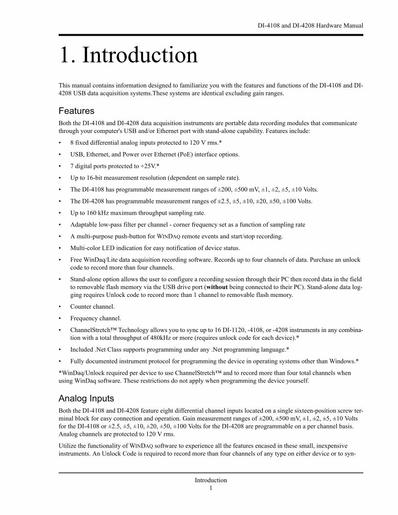
1. IntroductionThis manual contains information designed to familiarize you with the features and functions of the DI-4108 and DI-4208 USB data acquisition systems.These systems are identical excluding gain ranges.
FeaturesBoth the DI-4108 and DI-4208 data acquisition instruments are portable data recording modules that communicate through your computer's USB and/or Ethernet port with stand-alone capability. Features include:
• 8 fixed differential analog inputs protected to 120 V rms.*
• USB, Ethernet, and Power over Ethernet (PoE) interface options.
• 7 digital ports protected to +25V.*
• Up to 16-bit measurement resolution (dependent on sample rate).
• The DI-4108 has programmable measurement ranges of ±200, ±500 mV, ±1, ±2, ±5, ±10 Volts.
• The DI-4208 has programmable measurement ranges of ±2.5, ±5, ±10, ±20, ±50, ±100 Volts.
• Up to 160 kHz maximum throughput sampling rate.
• Adaptable low-pass filter per channel - corner frequency set as a function of sampling rate
• A multi-purpose push-button for WINDAQ remote events and start/stop recording.
• Multi-color LED indication for easy notification of device status.
• Free WinDaq/Lite data acquisition recording software. Records up to four channels of data. Purchase an unlock code to record more than four channels.
• Stand-alone option allows the user to configure a recording session through their PC then record data in the field to removable flash memory via the USB drive port (without being connected to their PC). Stand-alone data log-ging requires Unlock code to record more than 1 channel to removable flash memory.
• Counter channel.
• Frequency channel.
• ChannelStretch™ Technology allows you to sync up to 16 DI-1120, -4108, or -4208 instruments in any combina-tion with a total throughput of 480kHz or more (requires unlock code for each device).*
• Included .Net Class supports programming under any .Net programming language.*
• Fully documented instrument protocol for programming the device in operating systems other than Windows.*
*WinDaq/Unlock required per device to use ChannelStretch™ and to record more than four total channels when using WinDaq software. These restrictions do not apply when programming the device yourself.
Analog InputsBoth the DI-4108 and DI-4208 feature eight differential channel inputs located on a single sixteen-position screw ter-minal block for easy connection and operation. Gain measurement ranges of ±200, ±500 mV, ±1, ±2, ±5, ±10 Volts for the DI-4108 or ±2.5, ±5, ±10, ±20, ±50, ±100 Volts for the DI-4208 are programmable on a per channel basis. Analog channels are protected to 120 V rms.
Utilize the functionality of WINDAQ software to experience all the features encased in these small, inexpensive instruments. An Unlock Code is required to record more than four channels of any type on either device or to syn-
Introduction1
DI-4108 and DI-4208 Hardware Manual
chronize multiple units when using WinDaq software. There are no restrictions when programming the instruments yourself.
Digital I/OThe DI-4208 contains seven digital ports, which may be used as a general-purpose digital input or for a specific func-tion as designated on the device. Digital port D0 may be used for WinDaq Events; Digital port D1 may be used for WinDaq remote Start/Stop; Digital port D2 may be used for rate measurements; Digital port D3 may be used for counts; Digital ports D4 and D5 are general purpose digital input ports. Please Note: Digital outputs are not supported in WinDaq software. Each port may be configured as a switch using either the provided protocol or .Net class.
SoftwareAll software required to record and playback waveforms is included with the purchase of any DI-4108 or 4208 data acquisition system via download. Use the WinDaq Dashboard to access WinDaq Acquisition software or to setup the stand-alone configuration.
WINDAQ® Recording and Playback SoftwareWINDAQ Acquisition and WINDAQ Waveform Browser allow you to record and playback data acquired through your instrument. WINDAQ software is an invaluable resource to record and analyze your data and is available for free from our web site (www.dataq.com).
WINDAQ Lite Data Acquisition software (free) can be used to record waveforms directly and continuously to disk while monitoring a real time display of the waveforms on-screen. It operates, displays, and records up to four chan-nels in real time. An optional unlock code is available to record the rest of the channels on the device or to allow you to sync multiple units.
WINDAQ Waveform Browser playback software (also known as “WWB”) offers an easy way to review and analyze acquired waveforms. A built-in data file translator allows the user to display multiple waveforms acquired by WINDAQ Acquisition software or any of a wide range of data acquisition packages. The software’s disk-streaming design allows data files of any length to be graphically displayed rapidly, in normal or reverse time directions. Seven standard cursor-based measurements, frequency domain, and statistical analysis functions help simplify waveform analysis and interpretation. WINDAQ Waveform Browser is free and installed when installing WINDAQ Software.
HelpAll WINDAQ software utilizes context-sensitive help. Help may be accessed through the Help menu or by pressing the F1 key with any pull-down menu item selected. This will take you directly to the Help topic most relevant to that par-ticular function or feature. Help topics discuss in detail each function available in the software.
Introduction2
DI-4108 and DI-4208 Hardware Manual
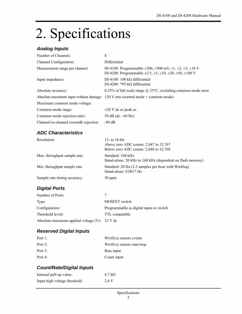
2. SpecificationsAnalog InputsNumber of Channels: 8
Channel Configuration: Differential
Measurement range per channel: DI-4108: Programmable ±200, ±500 mV, ±1, ±2, ±5, ±10 VDI-4208: Programmable ±2.5, ±5, ±10, ±20, ±50, ±100 V
Input impedance: DI-4108: 100 k differentialDI-4208: 795 k differential
Absolute accuracy: 0.25% of full scale range @ 25°C, excluding common mode error
Absolute maximum input without damage: 120 V rms (normal mode + common mode)
Maximum common mode voltage:
Common mode range: ±20 V dc or peak ac
Common mode rejection ratio: 50 dB (dc - 60 Hz)
Channel-to-channel crosstalk rejection: -80 dB
ADC CharacteristicsResolution: 12- to 16-bit
Above zero ADC counts: 2,047 to 32,767Below zero ADC counts: 2,048 to 32,768
Max. throughput sample rate: Standard: 160 kHzStand-alone: 20 kHz to 160 kHz (dependent on flash memory)
Min. throughput sample rate: Standard: 20 Hz (2.2 samples per hour with WinDaq)Stand-alone: 0.0017 Hz
Sample rate timing accuracy: 50 ppm
Digital PortsNumber of Ports: 7
Type: MOSFET switch
Configuration: Programmable as digital input or switch
Threshold levels TTL compatible
Absolute maximum applied voltage (V): 25 V dc
Reserved Digital InputsPort 1: WINDAQ remote events
Port 2: WINDAQ remote start/stop
Port 3: Rate input
Port 4: Count input
Count/Rate/Digital InputsInternal pull-up value: 4.7 k
Input high voltage threshold: 2.4 V
Specifications3

DI-4108 and DI-4208 Hardware Manual
Input low voltage threshold: 0.8 V
Terminal count: 65,535
Maximum rate frequency: 50 KHz with one enabled channel20 KHz with 2-4 enabled channels10 KHz with 5-7 enabled channels
Minimum rate frequency: 0.5 Hz
Maximum count frequency: 50 kHz
Digital Ports Programmed as SwitchMaximum drain voltage: 25V
Maximum sink current: 100 mA
Ethernet InterfaceType: 10/100Base-T
Connector: RJ-45
Protocol: TCP/IP
Server Type: DHCP or Fixed IP
Removable MemoryType: MLC, pSLC, or SLC flash memory (with USB SD card reader); USB
thumb drive
Required Format: FAT32
Number of Channels: 1; Unlock code required for 2 or more
Indicators and ConnectionsUSB Interface: USB 2.0 (mini-B style connector)
Button: Multi-function control (Start, Stop, Save Configuration, Apply Configu-ration)
USB A Connector (Drive): USB drive for Stand-alone data loggingCannot be used concurrently with the USB interface
Input connections: Two 16-position screw terminal strips
Status LED: One multicolor LED for status indication
USB ChannelStretch™ OperationTotal Max Units: 16
Max Channel Count: 128 Analog, 112 Digital
Max Throughput: ≥480 kHz (higher speeds may result in data loss)
Channel skew between any 2 units: 10 µS, typical
Synchronization Conditions: Syncs with any combination of DI-1120, DI-4108, DI-4208, and DI-4718B USB instruments.All synced instruments must operate at the same sample rate per channel, regardless of channel number, type, or range.All instruments must be connected to the same USB controller. The use of USB hubs are recommended to meet this requirement.
Specifications4
DI-4108 and DI-4208 Hardware Manual
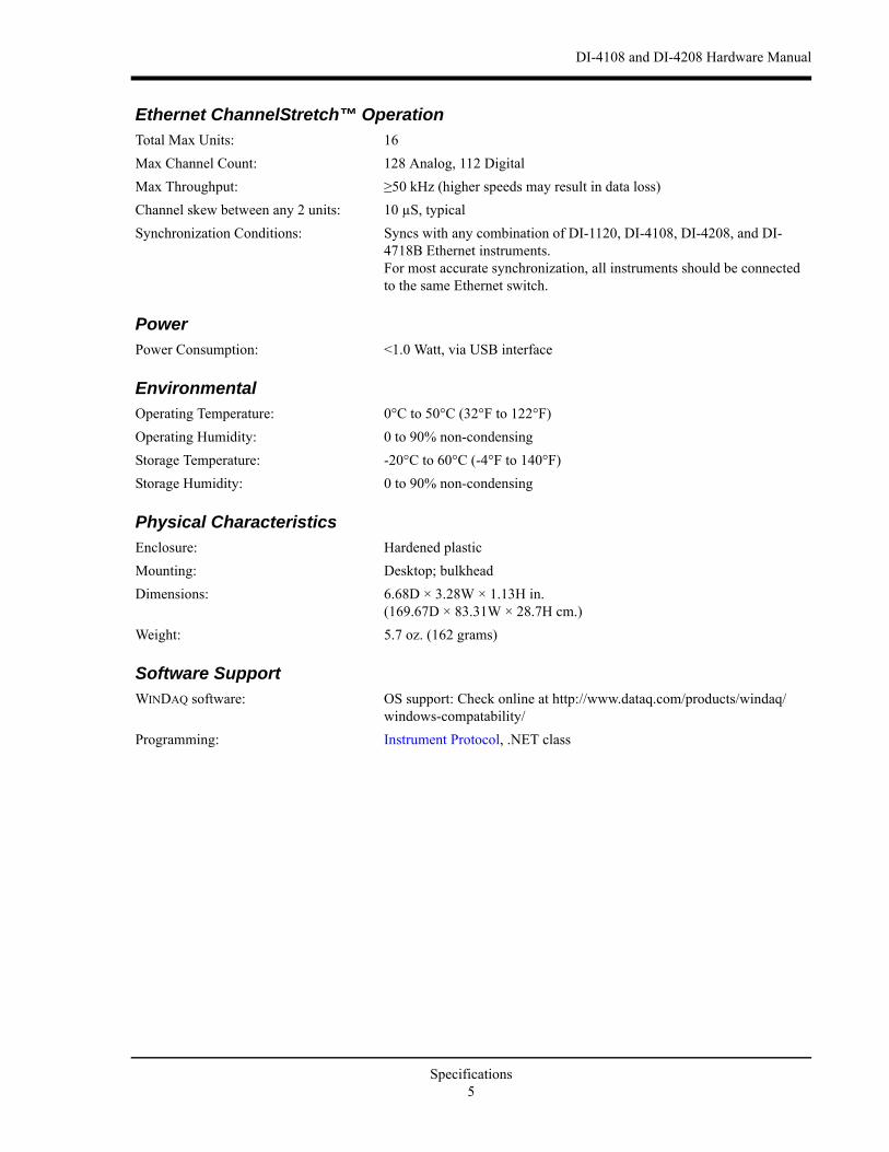
Ethernet ChannelStretch™ OperationTotal Max Units: 16
Max Channel Count: 128 Analog, 112 Digital
Max Throughput: ≥50 kHz (higher speeds may result in data loss)
Channel skew between any 2 units: 10 µS, typical
Synchronization Conditions: Syncs with any combination of DI-1120, DI-4108, DI-4208, and DI-4718B Ethernet instruments.For most accurate synchronization, all instruments should be connected to the same Ethernet switch.
PowerPower Consumption: <1.0 Watt, via USB interface
EnvironmentalOperating Temperature: 0°C to 50°C (32°F to 122°F)
Operating Humidity: 0 to 90% non-condensing
Storage Temperature: -20°C to 60°C (-4°F to 140°F)
Storage Humidity: 0 to 90% non-condensing
Physical CharacteristicsEnclosure: Hardened plastic
Mounting: Desktop; bulkhead
Dimensions: 6.68D × 3.28W × 1.13H in.(169.67D × 83.31W × 28.7H cm.)
Weight: 5.7 oz. (162 grams)
Software SupportWINDAQ software: OS support: Check online at http://www.dataq.com/products/windaq/
windows-compatability/
Programming: Instrument Protocol, .NET class
Specifications5

DI-4108 and DI-4208 Hardware Manual
3. InstallationThe following items are included with each DI-4108 or DI-4208 USB Data Acquisition System. Verify that you have the following:
• A DI-4108 or DI-4208 USB data acquisition instrument.
• 6-foot USB cable; Ethernet versions also provide a 5-foot Ethernet cable and an AC power supply if required (PoE versions do not come with a power supply).
• A DATAQ Instruments screwdriver for signal lead connections.
• A USB flash drive with WinDaq software. Can also be used for stand-alone data logging.
If an item is missing or damaged, call DATAQ Instruments at 330-668-1444. We will guide you through the appropri-ate steps for replacing missing or damaged items. Save the original packing material in the unlikely event that your unit must, for any reason, be sent back to DATAQ Instruments.
Install WINDAQ SoftwareAll software for the DI-4108 and DI4208 can be installed via a download-able executable directly from the DATAQ Instruments web site. The software is also available on the provided USB flash drive.
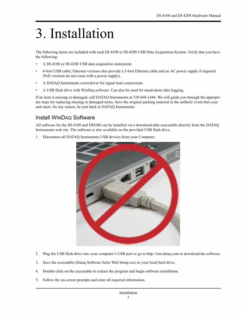
1. Disconnect all DATAQ Instruments USB devices from your Computer.
2. Plug the USB flash drive into your computer’s USB port or go to http://run.dataq.com to download the software.
3. Save the executable (Dataq Software Suite Web Setup.exe) to your local hard drive.
4. Double-click on the executable to extract the program and begin software installation.
5. Follow the on-screen prompts and enter all required information.
Installation7

DI-4108 and DI-4208 Hardware Manual
6. Software installation is complete - you will now see a “Successful Installation” box - click OK to exit WINDAQ
Installation.
You can now plug the device(s) into your PC. Click on the appropriate program group (specified above — default is Start > Programs > WINDAQ) and click on “DATAQ Instruments Hardware Manager” to access WINDAQ software.
Connect the Instrument to Your ComputerDI-4108 and DI-4208 instruments can be connected to your computer’s USB port using the provided USB cable. No external power is required when connected via the USB port. Ethernet products should initially be configured using the USB interface. Connect one end of the communications cable to the instrument port and the other to your PC’s port.
Note: Use a powered USB hub or a USB port on your PC. Non-powered USB hubs may not have sufficient power to run the instrument.
Installation8

DI-4108 and DI-4208 Hardware Manual
4. Controls, Indicators, and Connections
Mini-B USB ConnectionUse the supplied USB cable to connect and power the instrument through your computer’s USB port.
Screw TerminalsAll input signal connections are made to the 16-port screw terminals. Each terminal is labeled on the instrument case.
CAUTION
Never touch exposed screw terminal connector pins or screws.
To avoid ESD damage in handling the device, take the following precautions:
Ground yourself with a grounding strap or by touching a grounded object before and during your handling of the instrument.
Analog In Channels 1-8
Digital Ports 0-6
Even Marker Push Button
Activity LED
+5V Out Ground
Mini-B USB Connection
Bulkhead mounting ear
Bulkhead mounting ear
USB Drive
Ethernet Connection (optional)
Status
D0 D1 D2 D3 D4 D5 D6
Model DI-4108 or DI-4208
USB
Button
+5V GnD
CH8CH7CH6CH5CH4CH3CH2CH1
120 V rms
0-25V Max
CountRateRecordEventDrive
www.dataq.com
±2 to ±100 V F.S.
Ethernet
! !
Controls, Indicators, and Connections9
DI-4108 and DI-4208 Hardware Manual
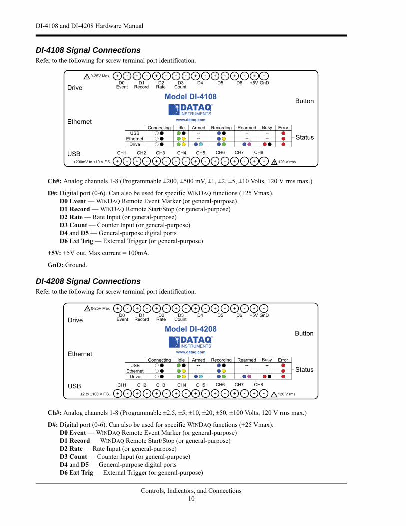
DI-4108 Signal ConnectionsRefer to the following for screw terminal port identification.
Ch#: Analog channels 1-8 (Programmable ±200, ±500 mV, ±1, ±2, ±5, ±10 Volts, 120 V rms max.)
D#: Digital port (0-6). Can also be used for specific WINDAQ functions (+25 Vmax).D0 Event — WINDAQ Remote Event Marker (or general-purpose) D1 Record — WINDAQ Remote Start/Stop (or general-purpose)D2 Rate — Rate Input (or general-purpose)D3 Count — Counter Input (or general-purpose)D4 and D5 — General-purpose digital portsD6 Ext Trig — External Trigger (or general-purpose)
+5V: +5V out. Max current = 100mA.
GnD: Ground.
DI-4208 Signal ConnectionsRefer to the following for screw terminal port identification.
Ch#: Analog channels 1-8 (Programmable ±2.5, ±5, ±10, ±20, ±50, ±100 Volts, 120 V rms max.)
D#: Digital port (0-6). Can also be used for specific WINDAQ functions (+25 Vmax).D0 Event — WINDAQ Remote Event Marker (or general-purpose) D1 Record — WINDAQ Remote Start/Stop (or general-purpose)D2 Rate — Rate Input (or general-purpose)D3 Count — Counter Input (or general-purpose)D4 and D5 — General-purpose digital portsD6 Ext Trig — External Trigger (or general-purpose)
Status
D0 D1 D2 D3 D4 D5 D6
Model DI-4108
USB
Button
+5V GnD
CH8CH7CH6CH5CH4CH3CH2CH1
120 V rms
0-25V Max
CountRateRecordEventDrive
www.dataq.com
±200mV to ±10 V F.S.
Ethernet
Status
D0 D1 D2 D3 D4 D5 D6
Model DI-4208
USB
Button
+5V GnD
CH8CH7CH6CH5CH4CH3CH2CH1
120 V rms
0-25V Max
CountRateRecordEventDrive
www.dataq.com
±2 to ±100 V F.S.
Ethernet
Controls, Indicators, and Connections10

DI-4108 and DI-4208 Hardware Manual
+5V: +5V out. Max current = 100mA.
GnD: Ground.
Connecting Signal LeadsConnect signal leads to the DI-4108 or DI-4208:
1. Insert the stripped end of a signal lead into the desired terminal directly under the screw.
2. Tighten the pressure flap by rotating the screw clockwise with a small screwdriver. Make sure that the pressure flap tightens only against the signal wire and not the wire insulation. Do not over-tighten.
3. Tug gently on the signal lead to ensure that it is firmly secured.
When an input signal is connected and WINDAQ Acquisition software is run, WINDAQ’s real time display immedi-ately reveals the input waveform on your computer’s monitor.
Analog Inputs
Eight differential analog inputs measure ±200, ±500 mV, ±1, ±2, ±5, ±10 Volts on the DI-4108or ±2.5, ±5, ±10, ±20,
±50, ±100 Volts for the DI-4208 (CH1 to CH8, programmable per channel) . Designed to withstand 120 Vrms.
798KAIN
798K10K
10K
AINVB
10K
VB10K 4.7K
VB
1500 pF
PGA
Controls, Indicators, and Connections11

DI-4108 and DI-4208 Hardware Manual
Use the following diagram to connect Analog Input Channel 1.
Specify a full scale range for the channel in the menu item Edit > Channel Settings.
Scroll through all enabled channels with the Next and Previous buttons.
DI-4108 Channel Settings DI-4208 Channel Settings
Status
D0 D1 D2 D3 D4 D5 D6
Model DI-4108 or DI-4208
USB
Button
+5V GnD
CH8CH7CH6CH5CH4CH3CH2CH1
120 V rms
0-25V Max
CountRateRecordEventDrive
www.dataq.com
±2 to ±100 V F.S.
Ethernet
Signal + Signal -
Controls, Indicators, and Connections12

DI-4108 and DI-4208 Hardware Manual
Low-pass FilterEach analog channel employs a low-pass filter with automatic corner frequency selection. The filter is a CIC (cas-caded integrator comb) type that uses as many as 512 samples per channel to calculate in real time as data is acquired. Filter response is optimized when sampling frequency is set to ten times the highest frequency of interest.
The DI-4108 and DI-4208 calculate its own Last Point, Maximum, Minimum, and Filter data making it available at the programming level. Acquisition methods “RMS” and “Frequency” are permanently disabled for the DI-4108 and DI-4208, as are Input Types “Nonlinear” and “Thermocouple” and selections for “Unipolar” and “Fahrenheit.”
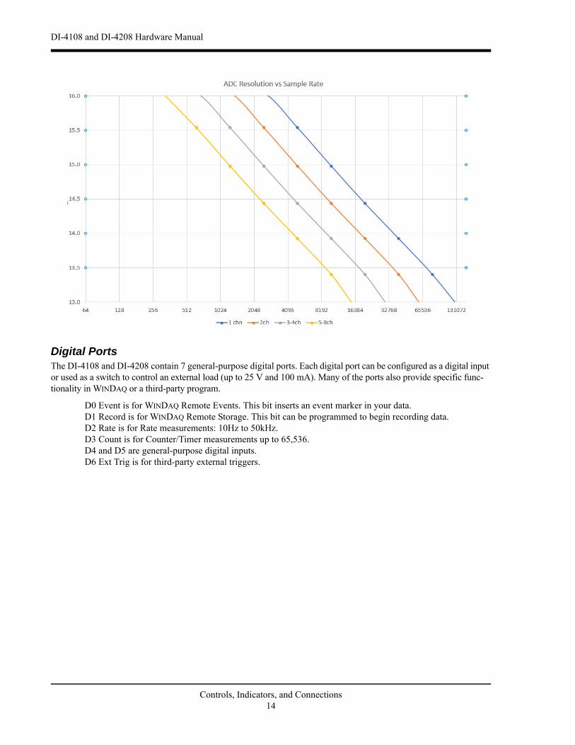
Resolution as a Function of Sample RateThe resolution of the DI-4108 and DI-4208 is a function of sample rate. The lower the sample rate the higher the res-olution. ADC resolution (R) is a function of selected sample rate per channel (F), and the number of enabled analog channels (C):
C Enabled Channels
1 1
2 2
4 3-4
8 5-8
Controls, Indicators, and Connections13
DI-4108 and DI-4208 Hardware Manual
Digital PortsThe DI-4108 and DI-4208 contain 7 general-purpose digital ports. Each digital port can be configured as a digital input or used as a switch to control an external load (up to 25 V and 100 mA). Many of the ports also provide specific func-tionality in WINDAQ or a third-party program.
D0 Event is for WINDAQ Remote Events. This bit inserts an event marker in your data.D1 Record is for WINDAQ Remote Storage. This bit can be programmed to begin recording data.D2 Rate is for Rate measurements: 10Hz to 50kHz.D3 Count is for Counter/Timer measurements up to 65,536.D4 and D5 are general-purpose digital inputs.D6 Ext Trig is for third-party external triggers.
Controls, Indicators, and Connections14

DI-4108 and DI-4208 Hardware Manual
Equivalent Digital I/O Circuit:
WINDAQ Remote Events (D0 Event)To use a switch closure or TTL signal to record WINDAQ Event Markers, connect signal leads to the appropriate Remote Control Event terminals on the DI-4108 or DI-4208 as shown below.
Once the switch closure or TTL signal is connected, activate Remote Events through WINDAQ Acquisition Software. Events may be automatically placed on the rising or falling edge of the trigger signal. Use the menu command Options > Remote Events + to set WINDAQ to place event markers on low-to-high transitions of the Event input. Use the menu command Options > Remote Events - to set WINDAQ to place event markers on high-to-low transi-tions of the Event input.
Dig In Dx
Dx
10
4.7K
+5
4.7K
Control
3.3V
Signal + Signal -
Status
D0 D1 D2 D3 D4 D5 D6
Model DI-4108 or DI-4208
USB
Button
+5V GnD
CH8CH7CH6CH5CH4CH3CH2CH1
120 V rms
0-25V Max
CountRateRecordEventDrive
www.dataq.com
±2 to ±100 V F.S.
Ethernet
Controls, Indicators, and Connections15
DI-4108 and DI-4208 Hardware Manual
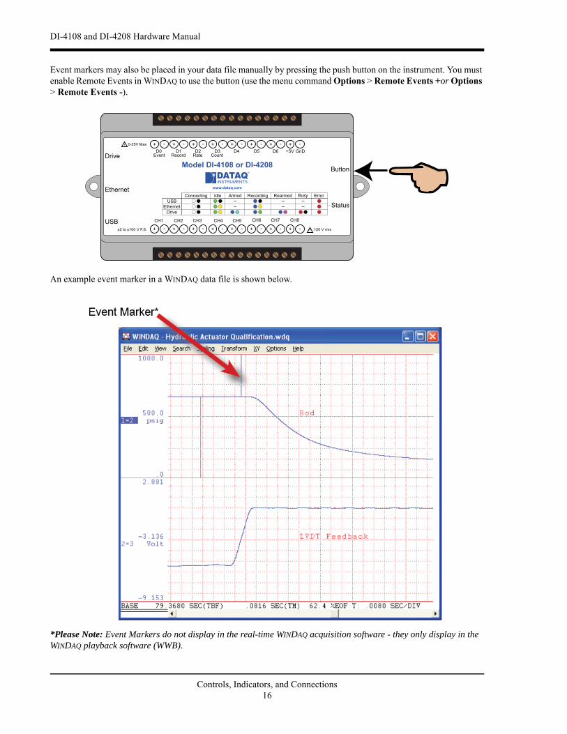
Event markers may also be placed in your data file manually by pressing the push button on the instrument. You must enable Remote Events in WINDAQ to use the button (use the menu command Options > Remote Events +or Options > Remote Events -).
An example event marker in a WINDAQ data file is shown below.
*Please Note: Event Markers do not display in the real-time WINDAQ acquisition software - they only display in the WINDAQ playback software (WWB).
Status
D0 D1 D2 D3 D4 D5 D6
Model DI-4108 or DI-4208
USB
Button
+5V GnD
CH8CH7CH6CH5CH4CH3CH2CH1
120 V rms
0-25V Max
CountRateRecordEventDrive
www.dataq.com
±2 to ±100 V F.S.
Ethernet
Controls, Indicators, and Connections16

DI-4108 and DI-4208 Hardware Manual
WINDAQ Remote Storage (D1 Record)To use a switch closure or TTL signal to begin recording data remotely, connect signal leads to the appropriate Remote Control Record terminals on the DI-4108 or DI-4208 as shown below.
Once the switch closure or TTL signal is connected, activate Remote Storage (Record) through WINDAQ Acquisition Software. Storage to Disk may be automatically placed on the rising or falling edge of the trigger signal. Use the menu command Options > Remote Storage 1 to set WINDAQ to begin recording on low-to-high transitions of the Record input. Use the menu command Options > Remote Storage 0 to set WINDAQ to begin recording on high-to-low transitions of the Record input.
WINDAQ Rate (D2 Rate)Enable channel 10 to record Rate, or the number of falling-edge transitions per unit of time that are applied to this input. Click on Edit > Channels in the WINDAQ Acquisition menu to open the Channel Selection grid. Channel 10 is
Signal + Signal -
Status
D0 D1 D2 D3 D4 D5 D6
Model DI-4108 or DI-4208
USB
Button
+5V GnD
CH8CH7CH6CH5CH4CH3CH2CH1
120 V rms
0-25V Max
CountRateRecordEventDrive
www.dataq.com
±2 to ±100 V F.S.
Ethernet
Controls, Indicators, and Connections17

DI-4108 and DI-4208 Hardware Manual
the designated Rate channel. Click on the Channel 10 channel box to enable/disable Rates. The Channel 10 channel box will display an “R” when enabled.
Connect any TTL pulse stream (25 VDC max) to the D2 Rate channel on the DI-4108 or DI-4208.
Select Channel 10 in the channel display, then select Edit > Channel Settings in the menu to specify a full scale range for the Rate channel. Ranges of 10, 20, 50, 100, 200, 500, 1000, 2000, 5000, 10000, 20000, and 50000 Hz are available. Choose a range that comes closest to your expected full scale rate or frequency. For example, if you need to
Status
D0 D1 D2 D3 D4 D5 D6
Model DI-4108 or DI-4208
USB
Button
+5V GnD
CH8CH7CH6CH5CH4CH3CH2CH1
120 V rms
0-25V Max
CountRateRecordEventDrive
www.dataq.com
±2 to ±100 V F.S.
Ethernet
Signal + Signal -
Controls, Indicators, and Connections18
DI-4108 and DI-4208 Hardware Manual
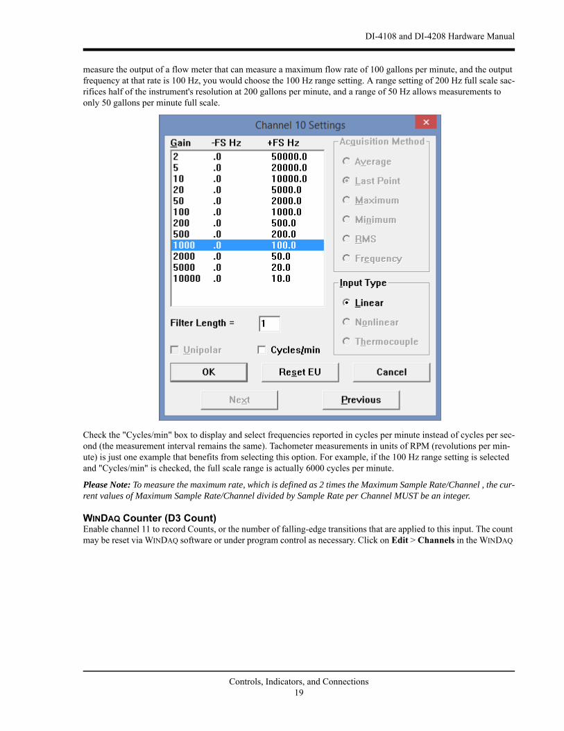
measure the output of a flow meter that can measure a maximum flow rate of 100 gallons per minute, and the output frequency at that rate is 100 Hz, you would choose the 100 Hz range setting. A range setting of 200 Hz full scale sac-rifices half of the instrument's resolution at 200 gallons per minute, and a range of 50 Hz allows measurements to only 50 gallons per minute full scale.
Check the "Cycles/min" box to display and select frequencies reported in cycles per minute instead of cycles per sec-ond (the measurement interval remains the same). Tachometer measurements in units of RPM (revolutions per min-ute) is just one example that benefits from selecting this option. For example, if the 100 Hz range setting is selected and "Cycles/min" is checked, the full scale range is actually 6000 cycles per minute.
Please Note: To measure the maximum rate, which is defined as 2 times the Maximum Sample Rate/Channel , the cur-rent values of Maximum Sample Rate/Channel divided by Sample Rate per Channel MUST be an integer.
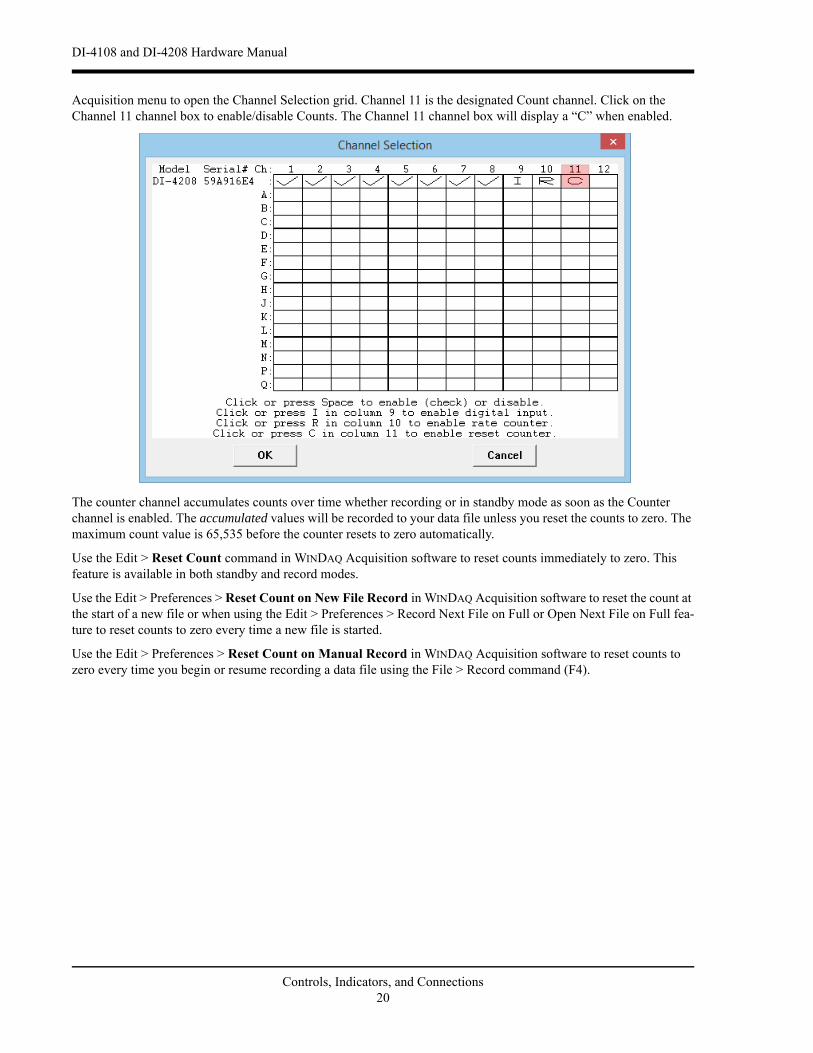
WINDAQ Counter (D3 Count)Enable channel 11 to record Counts, or the number of falling-edge transitions that are applied to this input. The count may be reset via WINDAQ software or under program control as necessary. Click on Edit > Channels in the WINDAQ
Controls, Indicators, and Connections19
DI-4108 and DI-4208 Hardware Manual
Acquisition menu to open the Channel Selection grid. Channel 11 is the designated Count channel. Click on the Channel 11 channel box to enable/disable Counts. The Channel 11 channel box will display a “C” when enabled.
The counter channel accumulates counts over time whether recording or in standby mode as soon as the Counter channel is enabled. The accumulated values will be recorded to your data file unless you reset the counts to zero. The maximum count value is 65,535 before the counter resets to zero automatically.
Use the Edit > Reset Count command in WINDAQ Acquisition software to reset counts immediately to zero. This feature is available in both standby and record modes.
Use the Edit > Preferences > Reset Count on New File Record in WINDAQ Acquisition software to reset the count at the start of a new file or when using the Edit > Preferences > Record Next File on Full or Open Next File on Full fea-ture to reset counts to zero every time a new file is started.
Use the Edit > Preferences > Reset Count on Manual Record in WINDAQ Acquisition software to reset counts to zero every time you begin or resume recording a data file using the File > Record command (F4).
Controls, Indicators, and Connections20
DI-4108 and DI-4208 Hardware Manual
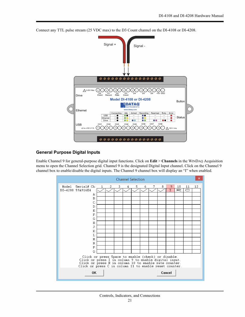
Connect any TTL pulse stream (25 VDC max) to the D3 Count channel on the DI-4108 or DI-4208.
General Purpose Digital Inputs
Enable Channel 9 for general-purpose digital input functions. Click on Edit > Channels in the WINDAQ Acquisition menu to open the Channel Selection grid. Channel 9 is the designated Digital Input channel. Click on the Channel 9 channel box to enable/disable the digital inputs. The Channel 9 channel box will display an “I” when enabled.
Status
D0 D1 D2 D3 D4 D5 D6
Model DI-4108 or DI-4208
USB
Button
+5V GnD
CH8CH7CH6CH5CH4CH3CH2CH1
120 V rms
0-25V Max
CountRateRecordEventDrive
www.dataq.com
±2 to ±100 V F.S.
Ethernet
Signal + Signal -
Controls, Indicators, and Connections21

DI-4108 and DI-4208 Hardware Manual
Channel 9 records and displays all the digital inputs, even the state of the Rate and Count inputs if those channels are enabled. With Channel 9 selected in the display window click Scaling > Digital Plot to show a digital display and make the data more meaningful on screen.
General Purpose Digital OutputsTake care when configuring the load to be switched to ensure that the digital port is not damaged:
Dx
+5 +V
Dx
+5 +V
Dx
+5 +V
Dx
+5
Dx
+5
Controls, Indicators, and Connections22
DI-4108 and DI-4208 Hardware Manual
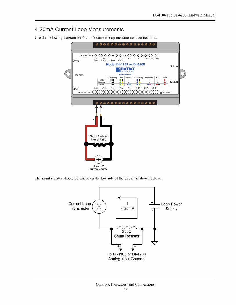
4-20mA Current Loop MeasurementsUse the following diagram for 4-20mA current loop measurement connections.
The shunt resistor should be placed on the low side of the circuit as shown below:
Status
D0 D1 D2 D3 D4 D5 D6
Model DI-4108 or DI-4208
USB
Button
+5V GnD
CH8CH7CH6CH5CH4CH3CH2CH1
120 V rms
0-25V Max
CountRateRecordEventDrive
www.dataq.com
±2 to ±100 V F.S.
Ethernet
Shunt Resistor Model R250
+ -
4-20 mA current source
I4-20mA
Current Loop Transmitter
Loop Power Supply
To DI-4108 or DI-4208Analog Input Channel
Shunt Resistor
+ -
+-
Controls, Indicators, and Connections23

DI-4108 and DI-4208 Hardware Manual
Set the engineering units as desired and define upper/lower levels in WINDAQ as 1V = 4mA for the low value and 5V = 20mA for the high value. For example, when using WINDAQ Acquisition software, in the EU Settings dialog box:
Enter the following values:
Visit our website at http://www.dataq.com/blog/data-acquisition/4-20-ma-current-loop-measurements/ to address all popular 4-20mA configurations.
You can also associate these values to a physical measurement such as pressure, load, flow, torque, etc. Read the Help files for more information regarding Engineering Units Settings.
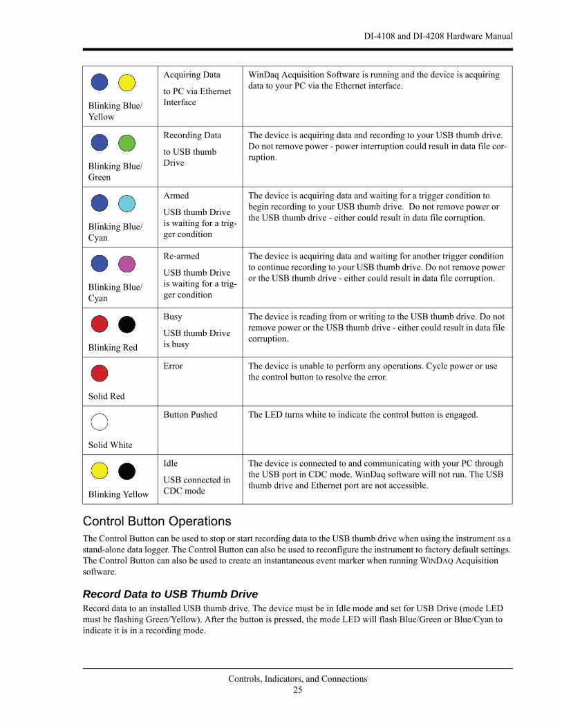
Mode LED IndicatorIndicates what mode the instrument is currently in. Use the chart on the top of the instrument for quick reference. Use the table provided below for a more detailed description of each available state as well as a description of some states not displayed on the label.
Volt EU EU Tag
Upper Level 5 20mA
Lower Level 1 4
State Mode Description
Connecting The device is looking for a connection to your PC or USB thumb drive. It will check the USB interface first, then the Ethernet and USB thumb drive. Once a connection is established the device will enter Idle mode.Blinking White
Idle
USB Connected
The device is connected to and communicating with your PC through the USB port. The USB thumb drive and Ethernet port are not accessi-ble.
Blinking Green
Idle
Ethernet or USB Drive Connected
The device is connected to and communicating with your PC through the Ethernet port or the device is in Stand-alone mode. The USB inter-face is not accessible.
Blinking Green/Yellow
Acquiring Data
to PC via USB Interface
WinDaq Acquisition Software is running and the device is acquiring data to your PC via the USB interface.
Blinking Blue
Controls, Indicators, and Connections24
DI-4108 and DI-4208 Hardware Manual
Control Button OperationsThe Control Button can be used to stop or start recording data to the USB thumb drive when using the instrument as a stand-alone data logger. The Control Button can also be used to reconfigure the instrument to factory default settings. The Control Button can also be used to create an instantaneous event marker when running WINDAQ Acquisition software.
Record Data to USB Thumb DriveRecord data to an installed USB thumb drive. The device must be in Idle mode and set for USB Drive (mode LED must be flashing Green/Yellow). After the button is pressed, the mode LED will flash Blue/Green or Blue/Cyan to indicate it is in a recording mode.
Acquiring Data
to PC via Ethernet Interface
WinDaq Acquisition Software is running and the device is acquiring data to your PC via the Ethernet interface.
Blinking Blue/Yellow
Recording Data
to USB thumb Drive
The device is acquiring data and recording to your USB thumb drive. Do not remove power - power interruption could result in data file cor-ruption.
Blinking Blue/Green
Armed
USB thumb Drive is waiting for a trig-ger condition
The device is acquiring data and waiting for a trigger condition to begin recording to your USB thumb drive. Do not remove power or the USB thumb drive - either could result in data file corruption.
Blinking Blue/Cyan
Re-armed
USB thumb Drive is waiting for a trig-ger condition
The device is acquiring data and waiting for another trigger condition to continue recording to your USB thumb drive. Do not remove power or the USB thumb drive - either could result in data file corruption.
Blinking Blue/Cyan
Busy
USB thumb Drive is busy
The device is reading from or writing to the USB thumb drive. Do not remove power or the USB thumb drive - either could result in data file corruption.
Blinking Red
Error The device is unable to perform any operations. Cycle power or use the control button to resolve the error.
Solid Red
Button Pushed The LED turns white to indicate the control button is engaged.
Solid White
Idle
USB connected in CDC mode
The device is connected to and communicating with your PC through the USB port in CDC mode. WinDaq software will not run. The USB thumb drive and Ethernet port are not accessible.
Blinking Yellow
Controls, Indicators, and Connections25

DI-4108 and DI-4208 Hardware Manual
Stop Recording to USB Thumb DriveManually stop recording to the USB thumb drive (when the mode LED is flashing Blue/Green, Blue/Cyan, or Blue/Magenta). After the button is pressed the mode LED will flash Green/Yellow to indicate Idle.
Fix ErrorsThe Control Button can also be used to fix some common operating errors. When the instrument is in Error mode (mode LED is solid red), some action must be taken to fix the error before you can use it. Generally, the Control But-ton can be used to make the instrument operational again when in Error mode.
Switching between LibUSB and CDC Modes
The native communication mode of DI-4108 and DI-4208 instruments is LibUSB but it can be switched to the USB CDC (Communication Device Class). CDC mode allows the USB port of DI-4108 and DI-4208 devices to appear like a traditional RS-232 port, which is common across most operating systems and development languages. Please note: LibUSB communication is required for WinDaq Acquisition software and programming with our .NET SDK. Only switch to CDC mode when writing your own programs at the protocol level (for example, Python applications). Use the following sequence to switch your device to/from LibUSB/CDC modes:
1. Connect the device to your PC via the USB port.
2. Apply power to the device.
3. When mode LED stops blinking white and is in Idle mode, push and hold the Control button. This must be com-pleted within five seconds after the device is in Idle mode.
4. When the mode LED turns red, release the Control button.
5. The Mode LED will flash white then indicate Idle in either LibUSB or CDC mode:
• CDC mode: Blinking Yellow
• LibUSB mode: Blinking Green
Save Ethernet and Stand-alone configuration to Thumb Drive
Save Ethernet settings and/or stand-alone configuration settings using the Control Button. Ethernet and Stand-alone configurations can also be saved to the thumb drive via the Dashboard (preferred method). Device must be in Idle mode for Ethernet or USB thumb Drive (mode LED blinks green/yellow). The Unlock Code must be purchased for your device in order to save the stand-alone configuration.
1. Format your USB thumb drive using your PC.
2. Confirm device is in Idle mode for USB Flash Drive (mode LED blinks Green/Yellow).
3. Push and hold the Control button.
4. Plug the formatted (empty) thumb drive into the device (Drive) while holding the button in.
5. Release the button when the mode LED changes to Red/Black.
6. The device will read and load the configuration files to the thumb drive and revert to Idle mode when complete.
Configuration files include network.json (Ethernet configuration) and config.whd or config.whc (WinDaq configuration). Use the WinDaq Dashboard to create configuration files.
Controls, Indicators, and Connections26
DI-4108 and DI-4208 Hardware Manual
Apply Ethernet and Stand-alone Configuration to Device
Load Ethernet settings or stand-alone configuration settings using the Control Button. Ethernet and Stand-alone configurations can also be applied via the Dashboard (preferred method). Device must be in Idle mode for Ethernet or USB thumb Drive (mode LED blinks green/yellow). The Unlock Code must be purchased for your device in order to apply the stand-alone configuration.
1. Save configuration files to your USB thumb drive.
2. Confirm device is in Idle mode for USB Flash Drive (mode LED blinks Green/Yellow).
3. Push and hold the Control button.
4. Plug the thumb drive into the device (Drive) while holding the button in.
5. Release the button when the mode LED changes to Red/Black.
6. The device will read and load the configuration files to the device and revert to Idle mode when complete.
Configuration files include network.json (Ethernet configuration) and config.whd or config.whc (WinDaq configura-tion). Use the WinDaq Dashboard to create configuration files.
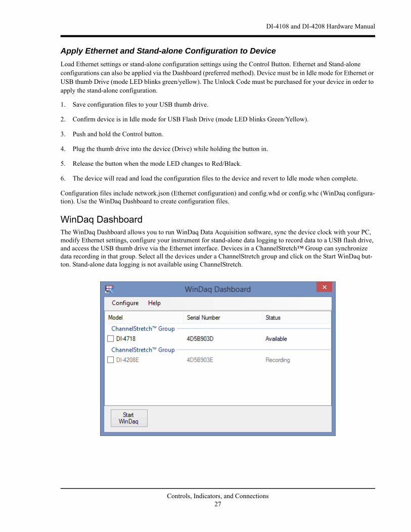
WinDaq DashboardThe WinDaq Dashboard allows you to run WinDaq Data Acquisition software, sync the device clock with your PC, modify Ethernet settings, configure your instrument for stand-alone data logging to record data to a USB flash drive, and access the USB thumb drive via the Ethernet interface. Devices in a ChannelStretch™ Group can synchronize data recording in that group. Select all the devices under a ChannelStretch group and click on the Start WinDaq but-ton. Stand-alone data logging is not available using ChannelStretch.
Controls, Indicators, and Connections27
DI-4108 and DI-4208 Hardware Manual
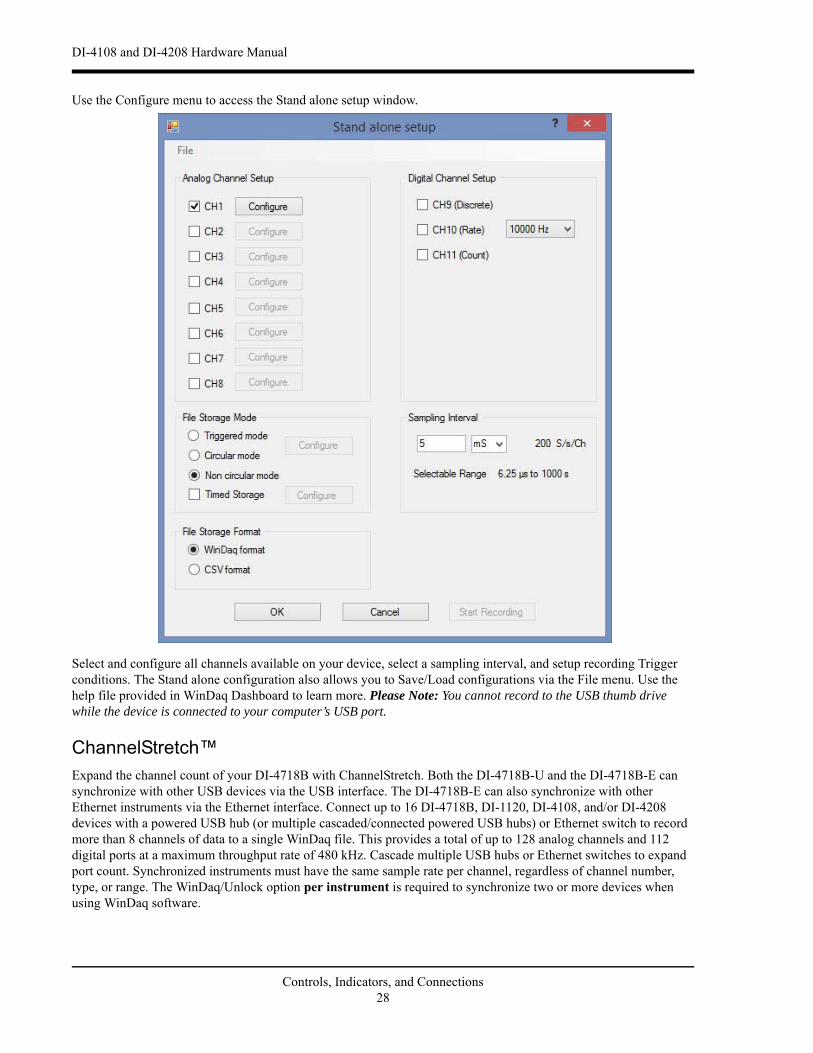
Use the Configure menu to access the Stand alone setup window.
Select and configure all channels available on your device, select a sampling interval, and setup recording Trigger conditions. The Stand alone configuration also allows you to Save/Load configurations via the File menu. Use the help file provided in WinDaq Dashboard to learn more. Please Note: You cannot record to the USB thumb drive while the device is connected to your computer’s USB port.
ChannelStretch™Expand the channel count of your DI-4718B with ChannelStretch. Both the DI-4718B-U and the DI-4718B-E can synchronize with other USB devices via the USB interface. The DI-4718B-E can also synchronize with other Ethernet instruments via the Ethernet interface. Connect up to 16 DI-4718B, DI-1120, DI-4108, and/or DI-4208 devices with a powered USB hub (or multiple cascaded/connected powered USB hubs) or Ethernet switch to record more than 8 channels of data to a single WinDaq file. This provides a total of up to 128 analog channels and 112 digital ports at a maximum throughput rate of 480 kHz. Cascade multiple USB hubs or Ethernet switches to expand port count. Synchronized instruments must have the same sample rate per channel, regardless of channel number, type, or range. The WinDaq/Unlock option per instrument is required to synchronize two or more devices when using WinDaq software.
Controls, Indicators, and Connections28
DI-4108 and DI-4208 Hardware Manual
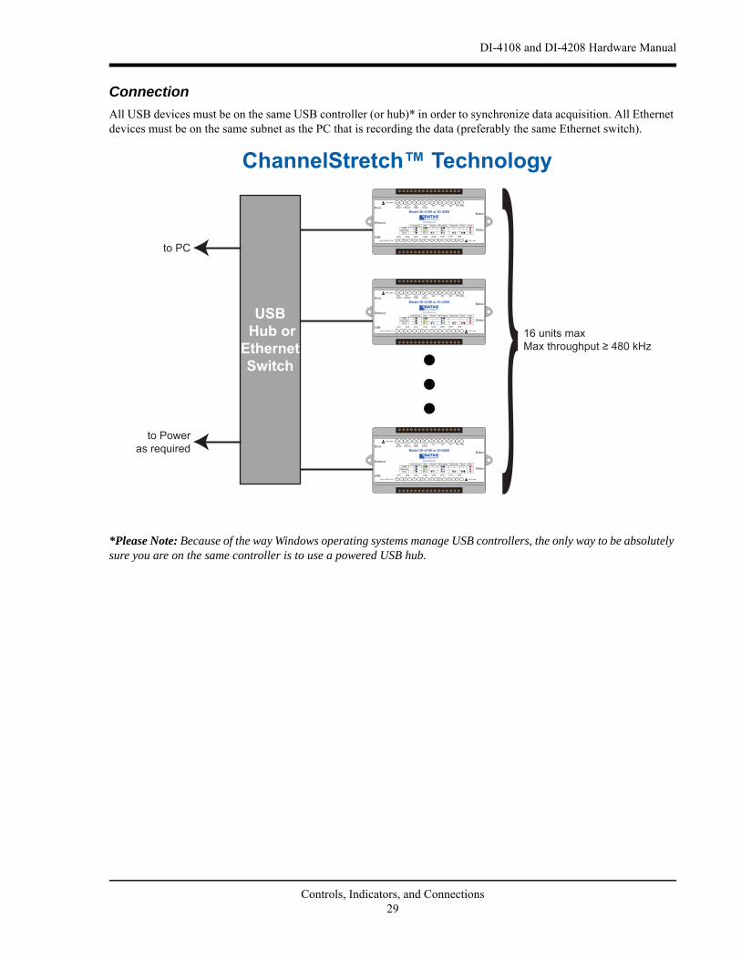
Connection
All USB devices must be on the same USB controller (or hub)* in order to synchronize data acquisition. All Ethernet devices must be on the same subnet as the PC that is recording the data (preferably the same Ethernet switch).
*Please Note: Because of the way Windows operating systems manage USB controllers, the only way to be absolutely sure you are on the same controller is to use a powered USB hub.
to PC
to Poweras required
USB Hub or Ethernet Switch
16 units max
ChannelStretch™ Technology
Status
D1 D2 D3 D5 D6
Model DI-4108 or DI-4208
USB
Button
+5V GnDV Max
CountRateRecordEventDrive
www.dataq.com
±2 to ±
Ethernet
Status
D1 D2 D3 D5 D6
Model DI-4108 or DI-4208
USB
Button
+5V GnDV Max
CountRateRecordEventDrive
www.dataq.com
±2 to ±
Ethernet
Status
D1 D2 D3 D5 D6
Model DI-4108 or DI-4208
USB
Button
+5V GnDV Max
CountRateRecordEventDrive
www.dataq.com
±2 to ±
Ethernet
Controls, Indicators, and Connections29
DI-4108 and DI-4208 Hardware Manual
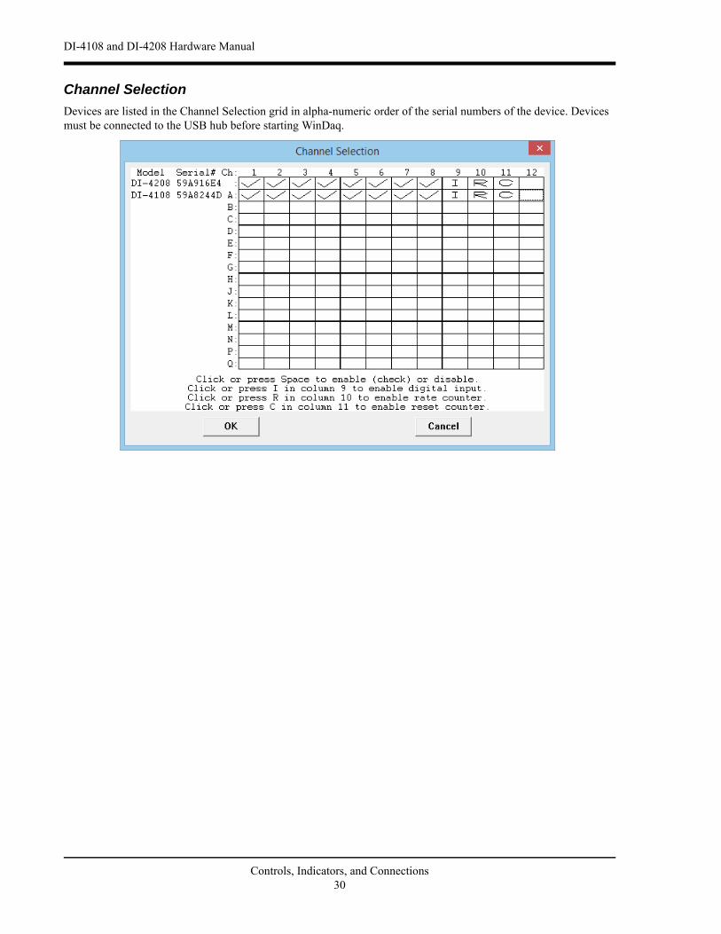
Channel Selection
Devices are listed in the Channel Selection grid in alpha-numeric order of the serial numbers of the device. Devices must be connected to the USB hub before starting WinDaq.
Controls, Indicators, and Connections30

DI-4108 and DI-4208 Hardware Manual
5. Unlock WinDaqThe DI-4108 and DI-4208 will record up to four channels using WinDaq/Lite software and a single channel to the USB thumb drive. An unlock code is required to record more than 4 channels or to use ChannelStretch™ to synchro-nize multiple instruments (unlock code required for each unit to be synchronized). Go to https://www.dataq.com/products/di-4108/ or https://www.dataq.com/products/di-4108/ to purchase either unlock code or call 330-668-1444. Once purchased, you will be given a Key code to enter into WinDaq (for WinDaq/Unlock) or the WinDaq Dashboard (for SA-Enabled).
WinDaq/UnlockAllows you to record more than four channels to WinDaq and unlocks ChannelStretch.
1. Start WinDaq Acquisition software.
2. Click the menu item Help > Unlock WinDaq.
3. Enter the Key in the appropriate dialog boxes.
4. Click OK.
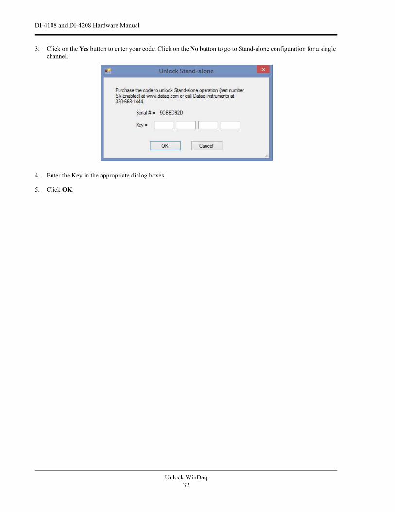
SA-EnabledAllows you to unlock all channels for stand-alone data logging as well as all the channels in WinDaq.
1. Start WinDaq Dashboard software.
2. Select your device and click the menu item Configure > Stand Alone Setup.
Unlock WinDaq31
DI-4108 and DI-4208 Hardware Manual
3. Click on the Yes button to enter your code. Click on the No button to go to Stand-alone configuration for a single channel.
4. Enter the Key in the appropriate dialog boxes.
5. Click OK.
Unlock WinDaq32

DI-4108 and DI-4208 Hardware Manual
6. Dimensional Drawing
Top View
Side View
All dimensions in inches
Dimensional Drawing33