DfYNS DOUENTATION CENTER - Defense Technical … DOUENTATION CENTER ... CORROSION OF BURIED PIPES...
32
-4 57 2 DfYNS DOUENTATION CENTER SCIENTIFIC AND TECHNICAL 'INFORMATION C AMERO11 STATION ALEXANDRIA. VIRGINIA UN('`/LA SIFIE'D
Transcript of DfYNS DOUENTATION CENTER - Defense Technical … DOUENTATION CENTER ... CORROSION OF BURIED PIPES...

-4 57 2
DfYNS DOUENTATION CENTERSCIENTIFIC AND TECHNICAL 'INFORMATION
C AMERO11 STATION ALEXANDRIA. VIRGINIA
UN('`/LA SIFIE'D

NOTICE: When government or other drawings, speci-fications or other data are used for any purposeother than in connection with a definitely relatedgovernment procurement operation, the U. S.Government thereby incurs no responsibility, nor anyobligation whatsoever; and the fact that the Govern-ment may have formulated, furnished, or in any waysupplied the said drawings, specifications, or otherdata is not to be regarded by implication or other-wise as in any manner licensing the holder or anyother person or corporation, or conveying any rightsor peinission to manufacture, use or sell anypatented invention that may in any way be relatedthereto.
C=) FOR OFFICIAL USE ONLY
It259Technical Report......CORROSION OF BURIED PIPES
i*-E E C."**-**.,*..)*'** 9 December 1963
C-2)
..... . .. .. 8
1 -~~~~~~~, U.... . S.NVLCVI.N IERNGLBRTR.... Port .. en.e.C liori

BestAvai~lable
Copy

CORROSION OF BURIED PIPES
Y-F015-99-012
Type B Final Report
by
H. R. Joerding
ABSTRACT
The objective of this task was to determine the relative merit and economy ofvarious types of external protective coverings for underground metal, cold pipes inthe highi7 corrosive soil at the Naval Ordnance Test Station, China Lake,California.
A highly corrosive area of the station was selected as a test site. A neiwork
of a number of test pipes with different commercial protictive coverings was connec-te:1 to an existing cold water line and tested for 49 months. Included in the test as Iconrroi were bart plpes of ,-.c:c .tee-, black steel; and copper. Visualinspections through testholes were made periodically to determine the peogress ofcorrosion. At the end of the test, all pipes were removed and brought to NCEL forclose examination.
-Final :esult, showed no corrosion on galvanized steel pipe that wasfactory-wrapped with resin-impregnated glass cloth. Thiz covering is very difficultto damage and imposes no special handling or installation requirements. Black steelpipe that was wrapped with black polyvinylchioride plastic tape was in excell'?ntcondition. Extreme care was necessary during installation to prevent cuts or nicksin the tape. The black steel pipes protected by bituminous coating, cured gilsonite,and uncured gilsonite had deteriorated badly.
Qualified requesters may obtain copies of this repoa, fremDDC.The Laboratory invites comment on this report, particuJarly or. the
result-, obtained by those who have aoplied the information.
17

INTRODUCTION
The desert soil at the Naval Ordnance Test Station, China Lake, California,a lk.:c-vy ~ccc-ntration of minerols in some areas, particularly the dry lake beds,
causing serious corrosion problems for underground pipes. In these areas of thestation, metal -,);pes have had very short lives. For example, an uncoated cist-ironwater pipe faiied -after about 3 years of service. In another case, a 2-inch standard-weight black steel pipe, asphalt-coated and wrapped, failed in approximately 1 year.Because of the failure of these and other piping systems and the trend toward expansionof facilities in highly corrosive areas, an investigation was undertaken to determinethe most su*table method of protecting cold water pipes against the corrosive elementsof this soil.
The task oblective was pursued by connecting underground test pipes to anexisting cold water Uine in a corrosive area and observing the progress of corrosionby periodic visual •nspection. Results of these inspections have been published.After 49 months of tes's, the pipes were removed and given a thorough and finhalinspection. The task is complete with this final report.
DESCRIPTIONS
Test Installation
The initial test installation wao made in June 1958. At that time, six 60-footlengths of 2-inch test pipe were (aid in parallel trenches 3 feet deep and spaced4 feet apart. The pipes .. joined by a 10-inch asbestos-cement pipe header at
.•"2- each end. and the entire netw•ork was connected to an existing 10-inch asbestos-V cement pipe that carried cold \ ct,'r. The network included one 60-foot ie-ngth,
made of 20-foot sections of galvanize- steel, black steel, and copper, connected
Technical Note N-373, Evaluation of Z",-Arnal Corrosion Protection Methodsfor Cold Pipes in a Desert Soil, by K. B. Edwards, 1 June 1959. TechnicalNote N-404, Evaluation of External Co-rcsion Protection Methods for Buried"Cc'id Pipes at China Lake, California, by H. R. Joerding, 1 March 1961.Ibid, N-441, 25 June 1962.
I!,i
together by dielectric couplines and four 60-foot lengths of black steel pipe protected Vby a bituminous coating, a black plastic tape, uncured gilsonite, and cured gilsonite,
respectively. The sixth length was galvanized steel and protected by a polyester-
resin-impregnared glass cloth wrap. It was purchased from Temploc; Incorporated,
Baldwin Park, California. *
sections might not give reliable test data because the length of each pipe was
shortened to 1/3 of full -,, -th, and because of the c-lose proximity of dissimilar
metals in soil of high el 'x. -. .... rductivity. As a result, three additional 60-foot
lengths of pipe were installed in July 1960, with one lingth each of galvanized
steel, black steel, and copper pipe, making a total of nine 60-foot lengths in the
test. The complete network is shown schematically in Figure 1 and described asfol lows:
Pipe No. 1. Galvanized steel pipe: Type 1, standard-weight. The
hot-dipped zinc-coated pipe conforms to Federal Specification WW-P-406b.
Pipe No. 2. Black steel pipe: Type 1, standard-weight. Conforms to
Federal Specification \WVW-P-406b. IPipe No. 3. Copper pipe: Type K, straight drawn tube. Conforms to
Fcdcra! Spcc.ficat.c- VWV.-T-799a. n
Pipe No. 4. Galvanized steel - black steel - copper pipe. Each length
conformed to the weights crnd spacifications for the corresponding type above. The
dielectric couplings used between each length had a metallic cover with a threaded
dielectric insert.
Pipe No. 5. Black steel pipe coated with bituminous coiting. The black
steel v;s the same as Pipe No. 2. The coating consisted of one coat of coal-tar
primer, covered by a coat of coal-tar enamel. Application of the coatIng wns
according to Specification 34Yc for Type 1i Orofective dssem and was purchased
under Mi'-P-15147.
* Th.s company is no longer in business, but the Durant Insulated Pipe Company,
325 Demeter Street, East Palo Alto, California, makes a similar product.
2
4

Pipe No. 6. Black steel pipe wrapped with plastic tape. The black steel wasthe same as Pipe No. 2. The tape was 3 inches wide, 10 mils thick, and made ofpolyvinyl chioride. The adhesive used on the tape was a rubber-base cement. It was
spirally wrapped with a 1/2-inch overlap. (The tape did not necessarily conform toany military specification.)
Pipe No. 7. Galvanized steel pipe factory-wrapped with resin-impregnatedglass cloth. The galvanized steel was the same as Pipe No. 1. The cloth was3 inches wide and about 40 mils thick. It was spirally wrapped with a 1/2-inchoverlap at the factory. The glass cloth conform-.s to Mil-C-19663 and the resin toMiI-R-7575B, Grade A, Class 0.
Pipe No. 8. Biack steel pipe with uncured gilsonite. The black steel wasthe same as Pipe No. 2. The gilsonite, an asphaltic resinous material in granularform, surrounded the pipe and extended radially 5 inches; no heat was applied tothe pipe to melt and consolidate the gilsonite into a coating.
Pipe No. 9. Black steel pipe with cured gilsonite. The black steel was thesame as Pipe No. 2. The gilsonite, an asphaltic resinous material in granular form,surrounded the steel pipe and extended radially 5 inches. To melt this m.t;erial andconsolidate it around the pipe, the pipe was heated for 72 hours at 250 F asrecommended by the supplier.
Inspection Procedure
The pipes were inspected periodically during the test through.three test holesat each pipe. On each inspection, a set of new holes was dug so the condition ofthe pipes could be determined in soil rot recently disturbed. The amount of rustand corrosion was observed and recorded; representative areas were photographed.There were five inspections; the first two at approximately 12-month intervals andthe last three at 6-month intervals. The intervals were shortened as the testprogressed because the rate of corrosion appeared to be accelerating.
In July 1962 the pipes were removed from the test and brought to NCEL.After a visual inspection of their general overall condition, they were thoroughlycleaned of rust and dirt by wire brushing so that micrometer measurements couldbe taken to determine the loss of metal from corrosion.
Determination of Metal Loss
Rough and uneven exterior surfaces on the pipe made it difficult to measureloss of metal; therefore, a statistical method was developed to obtain this information.
3

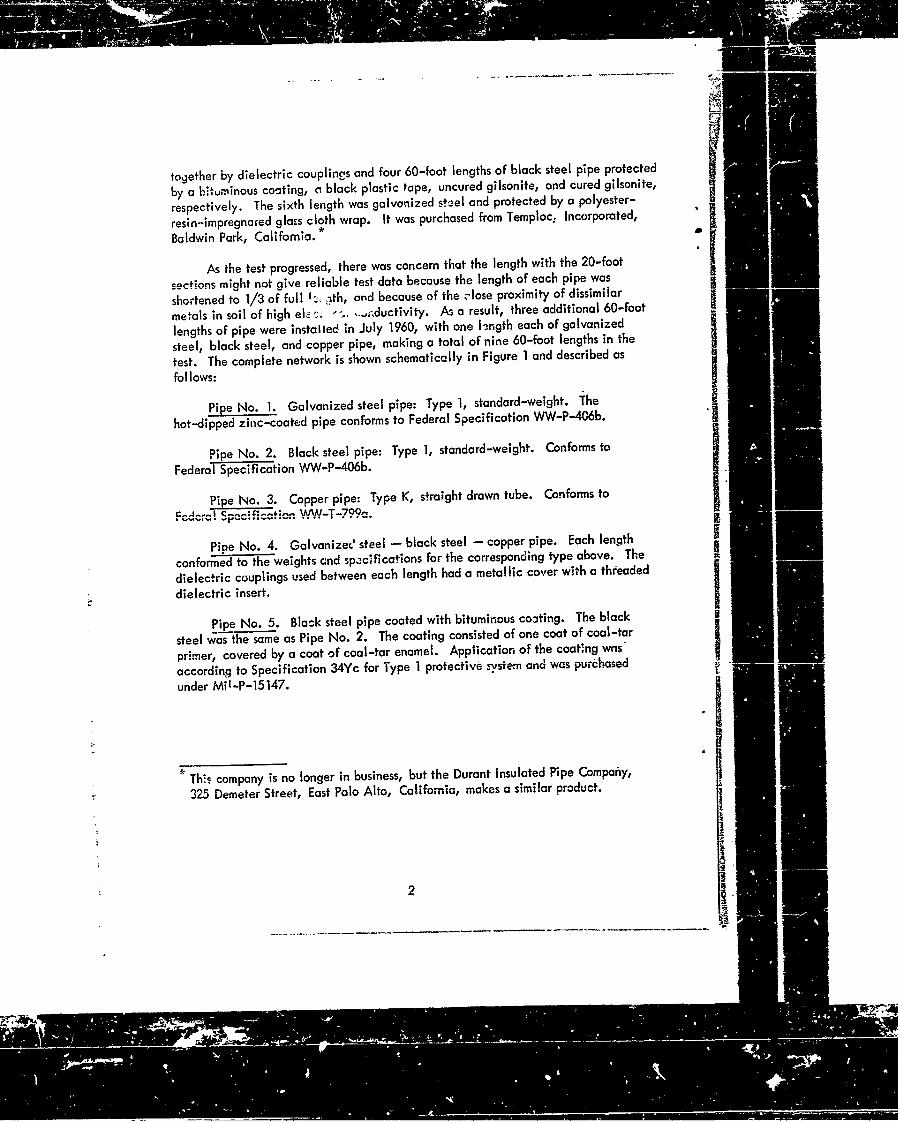
At 3-foot intervals on each pipe, one micrometer measurement of the outsidediameter was made, at a random location on the circumference. These measurementswere checked against the original specifications of the pipe diameters, and thepercentage of loss was calculated (Appendix A). Then each pipe was cut lengthwise,ane the thickness of the wall was measured at several places where extreme corrosionwas evidenr. From this data the maximum percentage of loss in wall thickness wasdetermined (Appendix A). The calculations for each pipe are summarized in Table I.
Soil Conditions
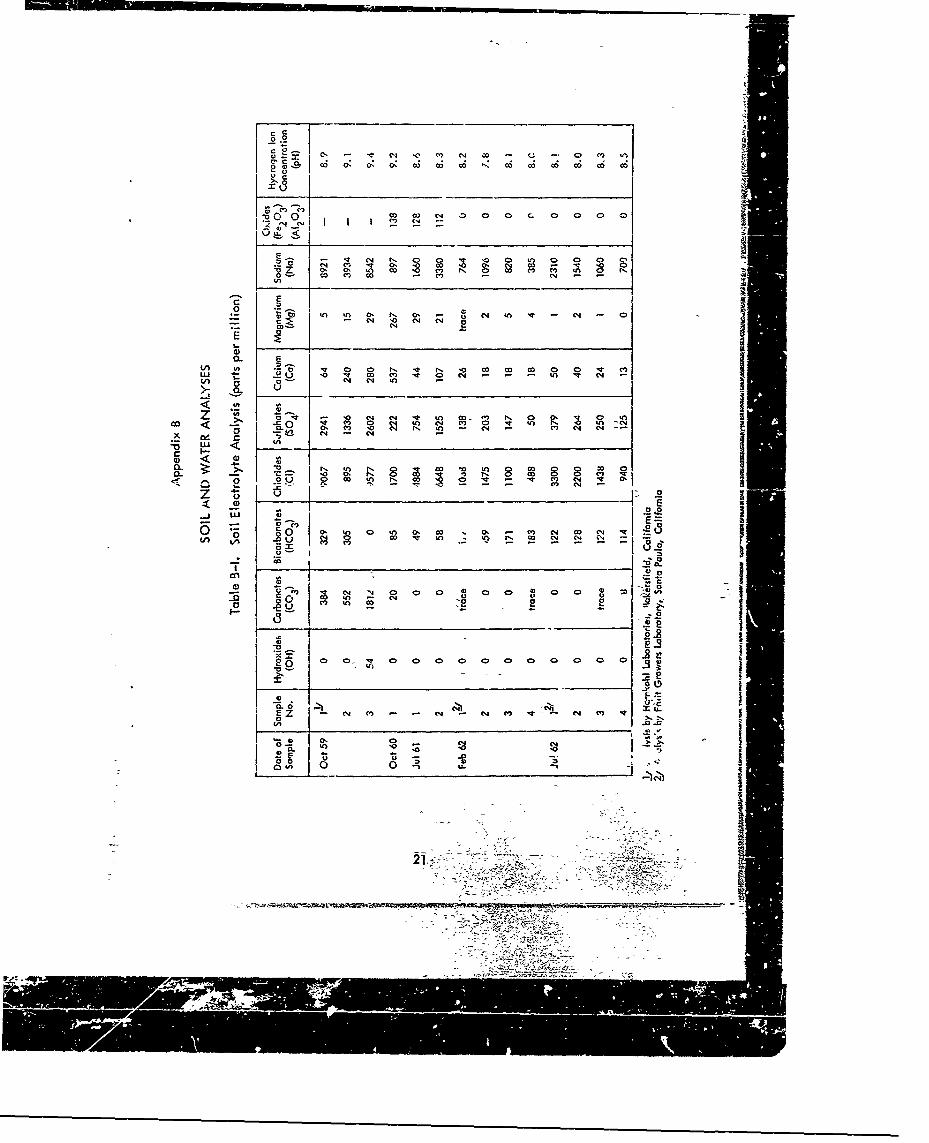
The corrosive character of the soil was determined by analyzing soil and groundwater, and by measuring the ground-water level. Samples of soil and of ground waterwere taken from test holes at each periodic inspection and analyzed. These analysesare tabulated in Appendix B. Both soil and water were slightly alkaline and had ahigh concentration of dissolved solids, particularly chlorides, sulfates, and sodium.The results of pH determinations showed a variation from 7.8 to 9.4 for soil, andfrom 7.4 to 8.2 for ground wator. The alkalinity of the ground water was producedby the presence of bicarbonates. The pH along with the chlorinity of the groundwater showed it to be about equivalent to ocean water in corrosivity. The chlorinityof the ground water varied from 9000 to 38, 000 ppm (parts per million); ocean waterhc's a chloriniiy of 19, 000 ppm.
A thermocouple tree was located near the center of the test site to obtaintemperatures of the air at ground level, and of the ground and ground water. Seventhermocouples were spaced at 9-inch intervals from 1 inch above ground level to53 inches below the surface. Temperature curves from 6 April 1962 to 17 July 1962(Figure 2) show that ground-water temperature was usually about 5 F below that ofthe ground. When this difference was noted between adjacent thermocouples, itwas assumed~that the ground-water level was between them. Figure 3 shows curvesof the approximate level of the ground water for the same period. This level variedfrom 21 to 47 inches below the soil surface; thus the pipes were submerged much ofthe time. ihe
* RESULTS " I
Each length of pipe is described as-1v r.ppeared at the final inspection atNOTS:
Pipe No. 1. Galvanized steel pipe: exposed 24 months. There was verylittle evidence of the zinc coating. Medium rust with tight scale covered 80% ofthe surface (Figure 4).
4

Pipe No. 2. Black steel pipe: exposed 24 months. There was medium toheavy rust with tight scale and pitting over the entire surface (Figure 5). Some ofthe pits penetrated over 50% through the wall. The surrounding soil was discoloredby the rust.
Pipe No. 3. Copper pipe: exposed 24 months. The pipe was covered witha white powder that could be brushed off, leaving the surface clean like a millfinish although there were small marks, like those of a ball peen, over the entiresurface. The surrounding soil was discolored dark green.
Pipe No. 4. Galvanized steel - black steel - copper pipe: exposed49 months.
a. Galvanized steel pipe: nearly all of the zinc coating was gone and theremaining portions could be easily removed by rubbing. The pipe had blackened,but there was very little rust and only 5% loss of metal.
b. Black steel pipe: there was liight to medium rust with loose scale overthe entire surface. No deep pitting was observed.
smllc. Copper pipe: this pipe was clean and uncorroded although there were
sma.. marks, like those of a ball peen, over the entire surface.
Pipe No. 5. Black steel pipe with bituminous coating: exposed 49 months.Only about 50% of the pipe was still coated at the end of the test. The bitumin"that came off seemed to disperse into the earth, discoloring the surrounding soil.The coating that remained on the pipe apparently did not offer much protectionas there was medium rust with loose scale and pitting over the entire surface.Some of the pits penetrated over 40% through the wall.
Pipe No. 6. Black steel pipe wrapped with plastic tape: exposed 49 months.In general, the tape was intact, in good condition, and gave excellent protection.The only corrosion occurred where the tape had been nicked by shovels when theinspection holes were dug (Figure 6); however, at these piaces the pits penevmrted-over 40% through the wall.
Pipe No. 7. Galvanized steel pipe wrapped with resin-impregnated glasscloth: exposed 49 months. This pipe was in excellent condition. There was nosign of rust nor deterioration of the zinc coating (Figure 7). The glass cloth wasalso in excellent condition with no evidence of deterioration (Figure 8).
4,
5

Pipe No. 8. Black steel pipe with uncured gilsonite: exposed 49 months.Medium to heavy rust, tight scale, and deep pits covered the pipe. The gilsonitedid not detericrate, but it apparently permitted gradual seepage of the corrosivesoil elements. It offered good protection for the first 24 months of the test.Hlowever, when rusting began, it progressed very fast. Many deep pits penetrated
the wall as deep as 85% (Figure 9).
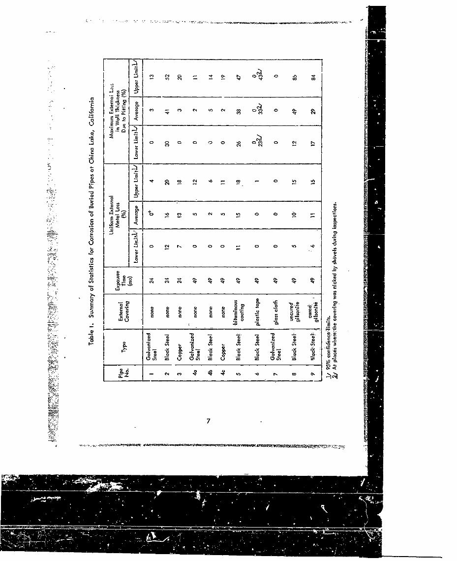
Pipe No. 9. Black steel pipe with cured gilsonite: exposed 49 months. Thegilsonite consolidated well and did not deteriorate, but it permitted overall light tomedium rust with loose scale and pitting that penetrated as much as 84% into thewall (Figure 10).
The plastic tape and giass-cloth provided the most protection, and gilsonite,cured and uncured, provided the least. However, uncured gilsonite gave goodprotection for the first 2 years. It is interesting to note that the individual pipesNos. 2 and 3, suffered more metal loss than their coupled counterparts 4b and 4 cdespite the fact that the former were in the ground about half as long.
COST
Current prices (1963) of the pipes and protective coverings (Table II) -cref. o. b. the vendor cnd do not include any costs for joints or connections. Therental cost of a steam generator for curing the gilsonite is also not included, -
For the test, a steam generator was used for 2 days at a cost of $100 per day. IBecause the zinc plating was unaffected, it is unnecessary to use galvanized pipewhen the glass cloth is applied. Black steel pipe would lower the cost.
CONCLUSIONS
1. Resin-impregnated glass cloth was the most satisfactory covering tested in thisenvironment. There was no rust or discoloration of the zinc plating or the steel I"pipe itself; there was no evidence of deterioration of the covering; and no specialhandling was required because the covering is hard and not easily damag. . I4.2. Plastic tape was also satisfactor/ where care-fully installed. It was rust-freeexcept where the tape had been damaged by shovels. There wao no evidenc& ofdeterioration of the tape; however, the tape is soft, easily cut or damaged, andspecial care is required to prevent nicks or cuts during installation. Even asharp rock in the backfill could cause damage.
3. The other three coatings (cured and uncured gilsonite and bitumin) permittedextensive rusting and are not satisfactory for use in this type of soil.
6
to C4 Nr co co
o - _ __ __ __ __ __ __ __ __ ___C__ _
M -q In~ C co 0c 0 o
0.VC' C-4
4-
0 0 •)0 to 0U') 0 )
k"0(I '
L" .0
04 *.'0 0-t
40 0C-
-7 4) - - u0 a
0 U
0 ~ ~ ~ ý C') 0 000
0U 0 0 0)
Ej a 0 4
c0 t c tn n tn c ~ Un W a
.0 V0.- 0- -2
In"' C It U
04) C. to 0 0 04) co 0-
'JO

Table II. Costs of 2-Inch Pipes and Coverings (1963)
Cost ofPipe Cost of Pipe1/ Covering covering1/ Total
($) ($)
Galvanized Steel 0.55 none - 0.55
Black Steel 0.45 none 0.45
Copper 1.20 none - 1.20
Black Steel 0.45 bituminous 0.45 0.90coating
Black Steel 0.45 plastic tape 0.45 0.90
Galvanized Steel 0.55 glass cloth 0.87 1.42 iBlack Steel 0.45 uncured 2.45 2.90SI gilsonite
04cured
Black Steel 0.45 gilsonite 2.45 2.90
1I/per foot of pipe
Z "

0961 Ajnr BS61 Punr
a.
0.ot
CL~
V C0.
00
U c
0 0
0
- U 0 * 00 a U2 -
u CIa CL CLC
CP IL
- aam
ft 0 -~ -
-p~o 0uo 40u -pu Cto 3o*i uwosies ojci m NI .-

1000.4 C N
.0 - N .
C4 0 04
- o 4- -
S cE
.0 tn -In -.
4-
C4 0 C
~L
'4
oIt.C4*
V 0i co 0 oooin Iojs4uu* eNjiaw

-- -
- 5k
II
II
Figure 4. Galvabnize steel pipe after 24 months exposure; gal cveanied
cotn erygn n 0 ceaeof medium t ev rust with tgtsaeadi
tight scale. 'I'1

Figure 6. Black steel pipe wrapped with plastic tape; the pipe wasrust-free except where the tape had been nicked by a Mshovel (see arrow).
NN
Figure 7. Galvanized steel pipe with a section of the resin-impregnatedglass cloth removed; after 49 months exposure the pipe wrsbright and clean.
12
* -U'* -- *!
I o
4' I
4,. II
0..2
14-
-- •- ,-•, , ,• I ,I I q • ld- == : = = :. .z"•ii i ! !
, , , e i I i I II I

Figure 8. Resin-impregnated glass cloth wrapping on a galvanized steelpipe; no signs of deterioration after 49 months exposure.
___ :~-4 I • - - • . . .-- "i -- •
Figure 9. Black steel pipe coated with uncured gilsonite; IOMY'( coverageof medium to heavy rust with tight scale and dee? pits (seearrow).
13
Appendix A
CALCULATIONS OF LOSS OF METAL ANL' WALL THICKNESS
by
W. Wilcoxsor.
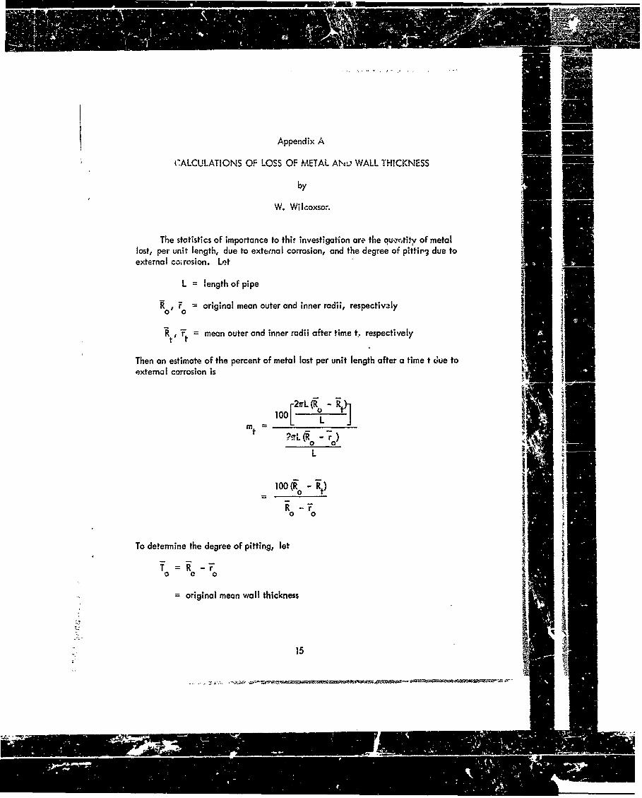
The statistics of importance to thir investigation are the quvrntitv of metallost, per unit length, due to external corrosion, and the degree of pittir, due toexternal co;rosion. Let
L = length of pipe
Ro' F = original mean outer and inner radii, respectively
Rt, I't = mean outer and inner radii after time t, respectively
Then an estimate of the percent of metal lost per unit length after a time t due toexternal corrosion is
2r~iL(R 0 -
mt -'.-. (Ro - r
=10Oo- ";)
R - )
0 0
To determine the degree of pitting, let
=original mean wiall thickness
S15
C-I7
R...° - " , ' i '" "'" '0 0 4, ;?f ~llll
'1 i iii i T determiineJJ th dere of pting let iiii ~S. . . . . . .. "- - • - "•' : " -•i • I I E0•• , 0 -r '1 I r

Tt = minimum wall thickness after time t (an average from severa! placesshowing extreme external pitting and corrosion).
The average loss in wall thickness, ti' due to internal corrosion and erosion is
ti = rt - r0
Therefore, the maximum percentage loss in wall thickness due to pitting, Pt' aftera time t due to external corrosion is
100 (o - t + ')Pt = - +-,•
0 t
An estimate of the 95% confidence limits* on m are
Mt= m 1.96 ) L m + Rt -t)
L R aT ( Rt)0 0 +
01-•[ARo (100 -mt)2 + AT nmt + AR' 1002]
An eslimate of the limits on Pt are
* On the average one out of twenty samples would be expected to exceed these
limits.
16

2 2 2 pptN (7, + (_- L\;t p t N'V ~ Ft) -\ t/
t Ptrvk s Tt6 t 0
196 -2 --22 -2(0 .2
p 1-96 - g 100 -pt)2 + A)t2 1002 A -t(0 tT + 0~
+ A~r 2 -10
1.6FT 2- +-2 -2 2 0 -21- 0 - L . (AT0 + 0 Art + Ar 0)+I0-AT t
Til CL1 0.07 T 0 (7
The manurfociuvel'lt, stmuhIA- -'- :-' I .eAT O0
According to standard shop practice, the tolerance on th rgnlradii are
670= 0. 005/2 = 0. 0025
AJR = 0. 005/2 =0. 00250
AR is the standard error of the mean, Rad ithsanrdeoroteman,
T. - They are e-stima*e b
At2 n (n - 1) X(t.k
A-T-4
k (k - -I) (Tk
5
IffW ,
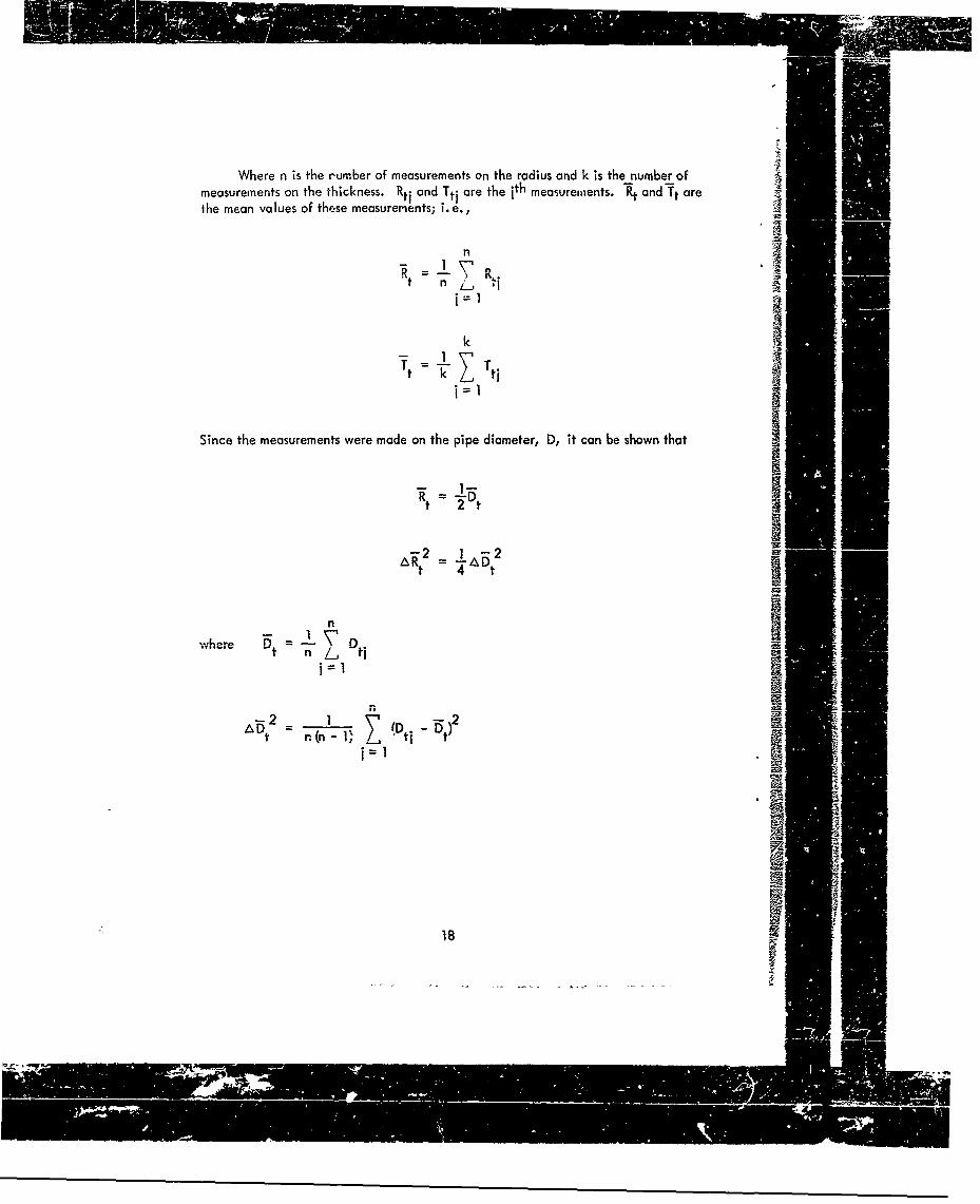
Where n is the r'urber of measurements on the radius and k is the number ofmeasurements on the thickness. Rt i and Tti are the ith measurements. Rýt and Tt arethe mean values of these measurements; i.e.,
n
t n
k
Since the measurements were made on the pipe diameter, D, it can be shown that
- I1-R t = Vt
At 4Dt
nIwhere 15t L tj
A t r (n IDDt -t)2
18

Sample Calculation
For biack sItel pipe coated with cured gilsonite (all measurements in inches)
Outside Diameter Inside Diameter
D 1 2.075
i 2.314 2 2.074
2 2.334 3 2.074
3 2.347 4 2.074
4 2.362 5 2.073
5 2. 340 6 2.073
6 2.367
7 2.370
8 2.327 Minimum Wall Thickness
9 2.330 1 0.095
10 2.330 2 0.103
11 2.342 3 0.120
12 2.363 4 0.130
13 2.342
14 2.352
15 2.365
16 2.297
17 2.333
S= 1.1875 A = 0.00250 0
r= 1.0335 Cr = 0.00250 0
T = 0.154 ,T = 0.007o 0
19

Results of computations:
1.171 -2= 5.853x10⁻⁶
"r = 1.037 = 6.333x 10⁻⁸
Tt=0.112 AT t = 6.317 x10⁻⁷
T = 3.417x10⁻³-3
mt = 10.695
Mt = 10.695 ± 4.296
P t = 2.851
Pt= 28.851 ± 11.888
MetalI Loss Maximum Loss ineta LWall Thickness___ Co)
Lower limit 6 17
Average 11 28
Upper l:'t. it 15 41
20
~~,,
.C (' C0N 0 . 0 C~c~~~
0) -, ? 0: 0: "!
0ý 0ý 0ý 0 i 7
-ý C a,4 0. 0 0 'o .fo 00 0D O o o cN C
00 C' (Zfl 0(- C'.)(. )- 0U.
'0.
0'L0 co CO m__ _ _ _C4_ _ _
0-
V, w)j.
G~~) N N 0I 00n
- 0 -t' C4 't In c n N"' ~ ~ " C') Ct) q~0~0
'o . 00 0n 0ý 00 0o 0T 0 0 0
-L I _ _ _ ___ ___
a.0 A00 ~ ~ 6-) - -. (N - 01 Nl C- OD C4 ~
.2.
U) 04 00 N
I xo C> ~ a C
(000
j V) 0 ~U-

0-, 0, -
-N C>.o
-o
.2. -0 04 N 'n C4)
Iý I-ttf Q C>) N
(DQ 8 V4 0 0 01
CL E. mo o44~ Ln:
v C4) m '
0`
0.0
, - a-28 CD 4 'co 0
co mc o C.
0. mR 0 0
CC
L 2
c 0 E
222

DISTRIBUTION LIST
SNDL No. of TotalCode Activ,,t.s Copies
1 10 Chief, Bureau of Yards and Docks (Code 42)23A 1 I Naval Forces Commanders (Taiwan only)
39B 2 4 Construtction 3cttohons
39D 10 10 Mobile Constructicn Bottulions
39E 3 3 Amphibious Constructi.n Boatiolons39F 1 2 Construction Battalion Bose Units
A2A 1 I Chief of Naval Research - OnlyA3 2 2 Chief of Novel Operation (OP-07, OP-04)
AS 5 5 Bureaus
B3 2 2 Colleges
E4 1 2 Laboratory ONR (Washingto.' D, (:.oiy)
E5 1 1 Research Office ONR (Pasadena only)
E16 1 I Training L'evice Center
F9 7 7 Station . CNO (Boston; Key West; Son Juan, Long Beach; San Diego;Treasure Island, and Rodman, C. Z. only)
F17 6 6 Communication Station (Son Juan; Son Francisco; Pearl Harbor; Adak,Alaska; and Guam only)
F41 I I Security Station
F42 1 1 Radio Station (Usa and Cheltanham oniy)
F48 I 1 Security Group Activities (Winter Harbor on'y)
H3 7 7 Hospital (Chelsea; St. Albons, Portsmouth, Va; Beaufort; Great Lakes;Son Diego; and Camp Pendleton unly)
H6 1 I Medical CenterJ1 2 2 Administration Command and Unit - BuPers (Great Lakes and
Son Diego only)J3 1 1 U. S. Fleet Anti-Air Warfare Training Cent.- (Virginia Beach only,
2 2 Amphibious Bases
J I4 1 9cccl::.g S*-c'on (Broolyn onlylJ34 I 1 Station - BuPers (Washington, D. C. only)
J46 I 1 Perstnnel Center
.J48 I 1 Construction Training Unit
J6C 1 1 School Avodemy
J65 I I School CEC Officers
.J84 1 1 School Postgraduate
J90 t Liol Supply Corps
IE

DISTRIBUTION LIST (Cont'd)
SNOL No. of TotalCode Activities Conlro5
j95 1 School War College
J99 1 1 Commnunication Training Center
L I 1 1I Shipyardsa
L7 4 4 Laboratory -B..,Zhips (Now London; Panama City; Corderock; andAnnapolis only)
L26 5 5 Naval Facilities - BuShips (Antiguc; Turks Island; Borbados;San Salvadwr; an~d Eleuthera only~
L30 II Sjibmarine Bose (Groto,., Corn., only)
L32 2 2 Naval Support Activities (London and Naples only)
L142 2 2j Fleet Activities -BuShips
h'27' 4 4 Supply Center
M28 6 6 Supply Depot (except Guantanamo 3oy; Subic Bay; and Yokosuka'
M61 2 2 Aviation Supply Offic.,
NI 6 18 BuDcocks Director, Overse7s Division
N2 9 27 Pub~ic Wori's Offices
N53 9 Construction Battalion Center
N5 5 5 Coiistructio,, Officer-in-ChargeIN7 I 1 Constructi-i Resi den t-Officer-in-Cliorge
N9 6 12 Public Works Cen.-r
N14 1 I Ilousir.g Activity
R9 2 2 Recruit Depoti,
RIO2 Supply Instiillotions (Albany and Barstow only)
R20 1 1 Marire Corps- Schoolrs (Quantico)
R64 3 3 Marint ZCips Base
R61 I Mal= cp Camp Detachment 'Tengc-a o..z,,
WIAI 6 6 Ai. Station
WIA2 35 35 Air Stat*n3*
wi Si.aiclril Auxiliary
WiC 4 4 Air Focility (Phoenix; Monterey; Oppomo; Noha; and Naples only)
6 6 Marine Corps Air Station (except Quontico)
WIH 9 9 Station - BuWaps (ex~cept Roto)
I I Doputy Chief of Staff, Reseacicl and Developmen~t, Headquarters,U. S. Marine Corps, Washington, D. C.
1 I Pre~idont, Mar~na Cc- ps Equipment Board, Marine Corps School,Quon'tiico, Va.
24
Iv.4 . ,II!IIIIIý

DISTRIBUTION LIST (Cont'd)
Noa.0 f TotalAct-te. Copies
1 1 Chef of Staff, U. S. Army, Chief of Research and Development, Department of zthe Army, Washington, D. C.
I 1 Office of the Cbi.*f of Eng.neert, I ssistant Chief of Enginrerin, for 'wvil Works,Department of the Army, Washington, ). C.
1 1 Chief of Engineers, Department of tl.e Army, Washin:ton, D.C., Attn: Engineering
Research and Devrlopment Division
1 1' Chief of Engir-eers, Department of the Army, Washington, D. C., Attn: ENGCW-OE
1 i Director, U. S. Army Engineer Research and Development Laboratories,Fcrt Bblvoir, Va., Attn: •nformaton Resources Branch
1 1 ASD (ASNXRR), Wright-Potterson Air Force Bose, Ohio
1 3 Headquarters, U. is. Air Force, Directorate of Civil Enginmeering, Washington, D. C.,Attn- AFOCE-ES
1 1 Commanding Ottecer, U. S. Naval Construct,aio Battalion Center, Port Hucrneme,Calif., Attn: Materiel Dept., Code 140
1 1 Deputy Chiif of Staff, Deve',pment, Director of Research and Development,Department of the Air Force, Was:.ington, D. C.
i1 Director, National Bureau of Standards, Department of Commeice, C.)nnecticutAvenue, Washington, 0. C
1 2 Office of the Director, U. b. Coast and ueodetic Survey, Washington, D. C.
1 20 Defense Documer"'-rcr" Ce--, Buldina 5. Cameron Staticn, Alexcrndrio, Va.
1 2 Director of Defense Research and Engineering, Deportment of Defense,
1 Commander, Pacific Missile Ran;e, Technical Documentation Section, P. O. Box 10,
Point Mugu,, Calif., Attn: 4332
1 2 Director, Bureau of Reclamation, Washington, D. C.
1 1 Facilities Officer, Code 108, Office of Naval Research, Wosh.ngton, D. C.
1 1 Federal Aviation Agenc,, 0f.cc of Management Services, Administrative ServicesDivision, Washin3 tpn, D. C., Attn: L:brary Bronch-
1 2 Commander Naval Beach Group TWO, U. S. Naval Amphibious Base, Little Creek,Norfolk, Va
1 1 Office ao Naval Resear - Br•nch Office, Navy No. 100, Box 39, FPO, New York
1 1 Commanding Officer, U. S. Naval Unit, U. S. Army Chemical Corps School,Fort McClellan, Ala.
1 1 U.S. Naval Research Laboratory, Chemistry Division, Washington, D. C.
1 Deputy Chief of Staff, Resenrch & Development Headquarters, U. S. Marine Corps,Washington, D. C.
1 1 Point Laboratory, U. S. Engineers Office, Clock Tower Building, Rock Island, III.
1 4 U.S. Army Material Command, Washinqton, D.C.
1 1 Commanding Officer, Signal Corps Engineering Labs, Fort Monmouth, N.J.
25
ail4
DISTRIBUTION LIST (Corit'd)
No. of TotalActivities copies
Chuef, Bureau of Ships, Navy Department, Washington, D. C,.Attn: Chief of Resiocrch and Development Division
I1 Officer in Char,-. U.'S. Naval Supply Research wid Development Facility, NavalSupply Center, Enyonne, N.J., At n: Library
1 Commander, Pacific Missile Range, Point Mugu, C.1it., Alto,: Technical Di-ector
11 Commander, Amphibious Force, U. S. Pacific Fleet, Son Diego, Calif.
1I Con mander, Amphibious Force, U. S. Atlantic Fleet, U. S. Naval Base, Norfoik, Va.
1 I Officer in Charge, U. S. Naval Supply Research and Development Facility, Naval
Supply Center, Bayonne, N. J.
1 Commiande., Norfolk Naval Shipyard, Portsmouth, Va., Attn: Metallurgical Laboratory
I Commander, Norfolk Naval Shipyard, Portsmouth: Va.. Attn: Chemical Laboratory
1 Co-rimanding Officer, Fleet Training Center, Navy No. 12L~, FPO, San Francisco
1 1 Cumnander, U .S. Naval Shipyard, Bostan, Mass., Attn. Material s a,id ChemicalLaboratory
1I Commander, U. S. Naval Shipyard, Brooklyn, Attn: Material Laboratory
1 1 Navy Liaison Officer, Detroit Arsenal, Centerline, Mich.
1I U.:S.' Army Corps of Engineors, Office of the District Engineer, St. PaulDistrict, 1217 U.S.P.O. and Customs Houise, St. Paul, Minn.
I U. S. Army Cold Regions Research and Engineering Laboratory, Corps ofEn gi neers, P.O. Box 282, Hanover, N. H.
1I Chief, Physical Research Branch, Research Division, U. S. Durpartment oECommorce, Bureau of Public Roads, Washington, D. C.
Mr. J. R. Moses, Diractor (C.400), Materials Testing und Evaluation Divi %ion,IDistrict Public Works Office, lAND, Navy No. 128, FPO, San Francisco
1 1 Mr. W. E. Edwards (Code M-220:WEE), Meter:als -ivesion, District Public WorksOffice, 14ND, Navy No. 128, FF0, San 'zranc~sco, Calif.
I Mr. William Crozoir, (C-',, 0-%30), DPWO, 12th Naval District, San B-uno, Calif.I Mr. Gordon Hano.rin, (Code 7036), Public Works Department, U. S. Navel
Orrdr.ea..e btation, China Lake, Calif.
I Mr. E. W. Watkins, (Code B.330), DPWO, i th Naval District, San Dii-go
I I Director, National Bureau oi ý,tondords, Department of Commerce, ConnecticutAvenue, Wash~ngton, D. C.. Attn: Mr. Melvin Romanoff
1 I Director, Fort Monmouth Office, Communications.Electron-cs CombatDevelopment:, Agency, B~uilding 410, Fort Monmouth, N. J.

I Ln
Ia &
-8 *<>.- 0
2 r ~I E - up -
v2 Ž c2. 0.0.~2 ~
o cp
Cu c .C0 >
00
_! 9
c a-
S- co-
5 a: - o z
Q ov-
cu. 0 q;0 x - L,;
V -.9 u
12
> tV gio 0u. -
Z C II c z d 5
~f 2~
4A3r 0-1 . I *~
I ~ILI
- R L-111