DEVONN Owner's Manual
76
21 254G2 - 304G2 – 404G2 Owner’s Manual
-
Upload
aghost-iraone -
Category
Documents
-
view
167 -
download
7
description
diesel maintenance
Transcript of DEVONN Owner's Manual
21
254G2 - 304G2 – 404G2
Owner’s Manual

21
FOREWORD The DONGFENG Brand wheeled tractor of Model DF-254G2/304G2/354G2/404G2 tractor is a newly developed product series of
Changzhou Dongfeng Agricultural Machinery Group Corp., Ltd. It is powered with the three-cylinder diesel engines that have the features of ample output, less vibration and low noise as well.
Model DF-254G2/304G2/354G2/404G2 tractors are of dual-function type for using in both paddy and dry fields. The designers have cogitated on some components, which can be selected for assembling in order to meet users’ various needs.
In order to fit in with the international market, some components for perfecting the tractor have been designed and developed, such as the hydraulic power steering, two-speed PTO, shuttle shift and so on. All of these have improved the performance of the tractor greatly.
This tractor series has the advantages of economic fuel consumption, easy operation, harmonious appearance, compact construction and simple maintenance. The tractor is also equipped with the linkage type double-acting clutch. It can be used for many jobs such as rototilling, plowing, harrow and loading, if suitable implements are matched. Really, this tractor series is of an ideal machine for home garden and lawn work, as well as the small or medium farms.
In order to meet users’ needs continuously, this tractor is subject to improvement without notice. It may be happened that there are some difference between the manual/illustrated parts catalogue and the structure of the real tractors. So the dealers or users are requested to provide serial number and manufacturing date of the tractor while placing order for spare parts.
Thank you for purchasing the Dongfeng Brand Tractor and cordially welcome your advice, suggestions and comments on our product so that we can make improvements timely in future.
Changzhou Dongfeng Agriculture Machinery Group Co., Ltd. China

21
CONTENTS
TECHNICAL SPECIFICATIONS OF THE TRACTORS………………….……..…1 SAFETY PRECAUTIONS…………………. …………………………. ..………...3 WORK SAFELY ALWAYS AND SAFETY RULES………….……….. ..………...17
1. REQUESTING FOR DEALER’S SERVICES …………..………….….……..21 2. INSTRUMENT PANEL AND CONTROLS …………..…………….….……...22
2.1 Indication Items ………………………………………………………... ..……...22 2.2 Switches ……………………………………. …………………...………...………22 2.3 Controls ……………………………………. …………………...………...………23
3. RUNNING-IN OF THE TRACTOR……………. ………………...…………..………27 3.1 Running-in of engine without load…………………………….………..……27
3.2 Running-in of the tractor without load…………………………………..……27 3.3 Running-in of the tractor with load……………………….……………..……27
3.4 Work after the running-in………………………………….…………….……28 4. OPERATION INSTRUCTIONS………………. ………………….……..……… ……29
4.1 Pre-start checks…………. …………………………………………………… ….29 4.2 Starting and stopping………………………………………….……………… ….29 4.3 Driving…………………………………………………………...……………… …30 4.4 Check during driving………. …………………………………………...………..31 4.5 Directions for operating differential lock pedal…………….…………...……..32 4.6 Control and usage of tractor’s working devices..……….……………….……32
5ADJUSTMENT OF THE TRACTOR……………………….…..………….………………36 5.1 Adjustment of the engine………….….. …….…………………………….… …36 5.2 Adjustment of the clutch………………………………..……………….…… ….36 5.3 Adjustment of the Toe-in………………………………. …….…..….….……..37 5.4 Wheel track adjustment…………………………………….………..…………37 5.5 Adjustment of Front Drive Axle ..………………………..……………………38 5.6 Use and Adjustment of the Full Hydraulic Steering System ……………39 5.7 Adjustment of the Brake ……………………..……………………..…….……..41 5.8 Adjustment of rear axle ………..……………………..…….…………….……42 5.9 Final Drive System…………………………..…………………………………….43 5.10 Adjustment of Air Brake Facilities (Optional)……………………………….43 5.11 Electrical System……………………………………………………………….44
6. LUBRICATION AND MAINTENANCE OF THE TRACTOR ……………………45 6.1 Oils to be used by the tractor and lubrication…………….…..……………45 6.2 Maintenance of the tractor………………………………..………………..…….46 6.3 Tractor storage…………. …...……………….………..……………..….…..……..47 6.4 Periodic check table…. ……………………..………..……………..……..…….48
21
7. CHECK AND MAINTENANCE……………………….……………….………… …49 7.1 Fuel…………………………. ………………………………………….………… ..49 7.2 Engine oil………………….. ……………………………………….…..………….50 7.3 Transmission oil………….. …………………………………………….…………51 7.4 Changing front axle case oil………….. ……….. ..………….. ..……...….…….52 7.5 Radiator…………………………………………………………………….………...52 7.6 Tire pressure……………………………………………………………….………53 7.7 Air cleaner……….. ……………………………………………………….……….54 7.8 Maintenance on free batteries………………………..…..….……..….…….54 7.9 3-Point Linkage…………. ………………………………..….………….………..55
8. TROUBLES AND TROUBLES-SHOOTING……………….….……………………..56 8.1 Engine…………. …………………………. …………….….…………………….56 8.2 Chassis…………. …………………………. …………….……………………….61 8.3 Electrical system…………. …………………………. ….………….……………64
Appendix 1 Moving Locus Diagram of Lifting Linkages………...............................................................67
Appendix 2 Diagram of Wiring (Combination Meter)…………………………………….…………….. … .68
Appendix 3 List of Rubber Oil-seal and O-ring seal…………………………………………………….…. ...69
Appendix 4 List of Bearings…………………………………….......................70
Appendix 5 Tightening Torque Table of Main Bolts and Nuts…............................................................................71
Appendix 6 List of Attached Tools……………………………………….…………….....71
Appendix 7 Packing List ………………………………………..…......72
MAINTENANCE SERVICE RECORD………………………. …………………………....73 PRE-DELIVERY SERVICE.………...…………………………………………………………………………....74

21
Technical Specifications of the Tractor Tractor Model DF254G2 DF304G2 DF354G2 DF404G2
Length 3269 3302 3302 3332 Width 1632 1632 1632 for 15-19.5
type 1632
To steering wheel 1555 1512 1512 1515
Height To the top of exhaust pipe 2032 1989 1989 1992
Wheel base (mm) 1700 1733 1733 1763 Front track 1185 1200 Wheel
track (mm) Rear track 1240 for14-17.5 NHS type
1242 for 15-19.5 type 1242 D
imen
sio
ns
(mm
)
Min. Ground clearance (mm) 300
Model Y385T-29 390T 390T TY395J ZN490T
Type Water cooled, Direct Injection Piston displacement (L) 1.532 1.812 1.812 2.23 2.835 12 hours rated power
(Kw/hp) 17.6/24 17.6/24 22/30 25.8/35 29.4/40
Rate fuel consumption (g/KW.h) =275 =275 =275 =251.6 =250
Rated speed (rpm) 2200 2200 2200
En
gin
e
Max Torque (N.m) =86.25 =86.25 =96.8 =117.8 =175 Clutch Double-acting clutch
Transmissions Shuttle, gearshift Steering gear Hydraulic steering gear
Brake Sealed shoe brake Rotating speed 540 rpm and 1000 rpm
PT
O
Spline size 6-tooth Ø35 Rectangular spline Electric circuit 12V Single phase & negative ground
Battery 6-QW-80L Starter QD1332
C QD138 QD138 QD1336 QD138
Fuel tank 35L Cooling system 10L 8.2L 8.2L 10L Engine sump 4L 5L 5L 4.5L 5.5L
Gearbox and rear axle 25L
Cap
acit
ies
Steering system 1.4L Weight 1600Kg 1650Kg 1650Kg 1700Kg 1750 Kg
Wheel types of the tractors Model DF254G2 DF304G2 DF354G2 DF404G2 Front 6.00-
12 23x8.54-
12 6.11-
12 28x9-
15 6.00-
12 28x9-
15 7.5-16 28x9-
15 Rear 8.3-24 14-
17.5NHS 9.5-24 15-19.5
9.5-24 15-19.5
12.4-24
15-19.5
21
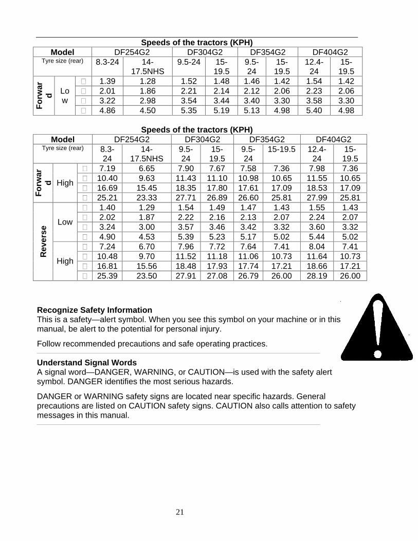
Speeds of the tractors (KPH) Model DF254G2 DF304G2 DF354G2 DF404G2
Tyre size (rear) 8.3-24 14-17.5NHS
9.5-24 15-19.5
9.5-24
15-19.5
12.4-24
15-19.5
1.39 1.28 1.52 1.48 1.46 1.42 1.54 1.42
2.01 1.86 2.21 2.14 2.12 2.06 2.23 2.06
3.22 2.98 3.54 3.44 3.40 3.30 3.58 3.30
Fo
rwar
d Lo
w
4.86 4.50 5.35 5.19 5.13 4.98 5.40 4.98
Speeds of the tractors (KPH) Model DF254G2 DF304G2 DF354G2 DF404G2
Tyre size (rear) 8.3-24
14-17.5NHS
9.5-24
15-19.5
9.5-24
15-19.5 12.4-24
15-19.5
7.19 6.65 7.90 7.67 7.58 7.36 7.98 7.36
10.40
9.63 11.43
11.10 10.98
10.65 11.55 10.65
16.69
15.45 18.35
17.80 17.61
17.09 18.53 17.09
Fo
rwar
d
High
25.21
23.33 27.71
26.89 26.60
25.81 27.99 25.81
1.40 1.29 1.54 1.49 1.47 1.43 1.55 1.43
2.02 1.87 2.22 2.16 2.13 2.07 2.24 2.07
3.24 3.00 3.57 3.46 3.42 3.32 3.60 3.32 Low
4.90 4.53 5.39 5.23 5.17 5.02 5.44 5.02
7.24 6.70 7.96 7.72 7.64 7.41 8.04 7.41
10.48
9.70 11.52
11.18 11.06
10.73 11.64 10.73
16.81
15.56 18.48
17.93 17.74
17.21 18.66 17.21
Rev
erse
High
25.39
23.50 27.91
27.08 26.79
26.00 28.19 26.00
Recognize Safety Information This is a safety—alert symbol. When you see this symbol on your machine or in this manual, be alert to the potential for personal injury.
Follow recommended precautions and safe operating practices.
Understand Signal Words A signal word—DANGER, WARNING, or CAUTION—is used with the safety alert symbol. DANGER identifies the most serious hazards.
DANGER or WARNING safety signs are located near specific hazards. General precautions are listed on CAUTION safety signs. CAUTION also calls attention to safety messages in this manual.

21
Follow Safety instructions Carefully read all safety messages in this manual and on your machine safety signs. Keep safety signs in good condition. Replace missing or damaged safety signs. Be sure new equipment components and repair parts include the current safety signs. Replacement safety signs are available from your DEVONN dealer. Learn how to operate the machine and how to use controls properly. Do not let anyone operate without instruction. Keep your machine in proper working condition. Unauthorized modifications to the machine may impair the function and/or safety and affect machine life. If you do not understand any part of this manual and need assistance, contact your DEVONN dealer.
Prevent Machine Runaway Avoid possible injury or death from machinery runaway. Do not start engine by shorting across starter terminals. Machine will start in gear, if normal circuitry is bypassed. NEVER start engine while standing on ground. Start engine only from operator’s seat, with transmission in neutral or park.
Use Seat Belt and Foldable ROPS Properly—Open Station When the ROPS is in the “up” or extended position, ALWAYS use your seat belt to minimize chance of injury from an overturn accident.
DO NOT use seat belt when ROPS is folded down
This tractor is equipped with a foldable Roll Over Protective Structure (ROPS). The ROPS (A) should be kept in the “up" or extended position (as pictured) with pins (C) retained with quick—lock pins (B), except when it is necessary to fold it for low clearance operations.
A—ROPS B—Quick-Lock Pins C—ping

21
Operate Tractor Safely Features designed into your tractor make operation Safer and let it perform a wide variety of jobs. Use your tractor only for specified jobs. It was designed to perform: implement carrier, load mover, remote power source, or transport unit—not a recreational vehicle.
Careless use or misuse can result in unnecessary accidents. Be alert to hazards of tractor operation.
Understand causes of accidents and take every precaution to avoid them. Most common accidents are caused from:
·Tractor misuse; ·Improper starting procedures ·Crushing and pinching during hitching ·Collisions with other motor vehicles ·Getting entangled in PTO shafts ·Falls from tractors
Avoid accidents by taking the following precautions:
Put transmission in NUETRAL and APPLY HAND BRAKE before dismounting.
Leaving transmission in gear with engine stopped will NOT prevent the tractor from moving.
Be sure everyone is clear off the tractor and attached equipment before starting engine.
Never try to get on or off a moving tractor.
When tractor is left unattended, place in NUETRAL, apply hand brake, lower implement to the ground, stop the engine, and remove the key.

21
Use Caution on Hillsides
Always wear seat belt with ROPS in upper position. Avoid holes, ditches, and obstructions which cause the tractor to tip, especially on hillsides. Avoid sharp, uphill turns. Never drive near the edge of a gully or steep embankment - it might cave in. Driving forward out of a ditch or mired condition or up a steep slope could cause tractor to tip over rearward. Back out of these situations if possible While mechanical front wheel drive greatly increases Traction, it DOES NOT increase stability of the tractor. With mechanical front wheel drive engaged, the tractor can climb steeper slopes but it does not become more stable. When this option is used, extra caution is needed on slopes. Compared with a 2-wheeI drive tractor, a front wheel drive tractor maintains traction on steeper slopes, increasing the possibility of a tip over. Danger of overturn increases greatly with narrow tread setting, at high speed. Hitch towed loads only to drawbar. When using a chain, take up the slack slowly.
Protect Against Noise
Prolonged exposure to loud noise can cause impairment or loss of hearing. Wear a suitable hearing protective device such as earmuffs or earplugs to protect against objectionable or uncomfortable loud noises.
Shift to Low Gear on Hills Shift to a low gear before descending a steep hill to improve your control of the tractor with little or no braking. Use engine braking to reduce speed before applying tractor brakes. Run-away tractors often tip over. Never coast downhill. When driving on icy, wet or graveled surfaces, reduce speed and be sure tractor is properly ballasted to avoid skidding and loss of steering control. For best control, engage mechanical front wheel drive (if equipped). Additional ballast may be needed for transporting heavy hitch mounted implements. When implement is raised, drive slowly over rough ground, regardless of how much ballast is used.
Keep Riders Off Machines Only allow the operator on the machine. Keep riders off. Riders on machine are subject to injury such as being struck by foreign objects and being thrown off of the machine. Riders also obstruct the operator’s view resulting in the machine being operated in an unsafe manner.
Freeing a Mired Machine Attempting to free a mired machine can involve safety hazards such as the mired tractor tipping rearward, the towing tractor overturning, and the tow chain or tow bar (Actable is not recommended) failing and recoiling from its stretched condition. Back your tractor out if it gets mired down in mud. Unhitch any towed implements. Dig mud from behind the rear wheels. Place boards behind the wheels to provide a solid base and try to back out slowly. If necessary, dig mud from the front of all wheels and drive slowly ahead.

21
If necessary to tow with another unit, use a tow bar or a long chain (a cable is not recommended). Inspect the chain for flaws. Make sure all parts of towing devices are of adequate size and strong enough to handle the load. Always hitch to the drawbar of the towing unit.
Do not hitch to the front push bar attachment point. Before moving, clear the area of people. Apply power smoothly to take up the slack: a sudden pull could snap any towing device causing it to whip or recoil dangerously.
Avoid High-Pressure Fluids Escaping fluid under pressure can penetrate the skin causing serious injury. Avoid the hazard by relieving pressure before disconnecting hydraulic or other lines. Tighten all connections before applying pressure.
Search for leaks with a piece of cardboard. Protect hands and body from high pressure fluids.
If an accident occurs, see a doctor immediately. Any fluid injected into the skin must be surgically removed within a few hours or gangrene may result. Doctors unfamiliar with this type of injury should reference a knowledgeable medical source.
Park Tractor Safely To park tractor safely: ·Disengage PTO; ·Lower equipment to the ground; ·Put gear shift lever in NUETRAL; ·Apply hand brake; ·STOP the engine; ·Remove key.
Before you leave the operator's seat, wait for engine and attachment parts to stop moving.

21
Handle Fuel Safely-Avoid Fires Handle fuel with care; it is highly flammable. Do not refuel the machine while smoking or when near open flame or sparks. Always stop engine before refueling machine. Fill fuel tank outdoors. Prevent fires by keeping machine clean of accumulated trash, grease, and debris. Always clean up spilled fuel. Prepare for Emergencies Be prepared if a fire starts. Keep a first aid kit and fire extinguisher handy.
Keep emergency numbers for doctors, ambulance service, hospital, and fire department near your telephone
Do Not Use Starting Fluid DO NOT use starting fluid in tractors equipped with an intake air heater system.
Tractors are equipped with an intake air heater system.
Wear Protective Clothing Wear close fitting clothing and safety equipment appropriate to the job.
Prolonged exposure to loud noise can cause impairment or loss of hearing.
Wear a suitable hearing protective device such as earmuffs or earplugs to protect against objectionable or uncomfortable Loud noises.
Operating equipment safely requires the full attention of the operator. Do not wear radio or music headphones while operating machine.
Work In Ventilated Area Engine exhaust fumes can cause sickness or death. If it is necessary to run an engine in an enclosed area, remove the exhaust fumes from the area with an exhaust pipe extension.
If you do not have an exhaust pipe extension, open the doors and get outside air into the area.
21
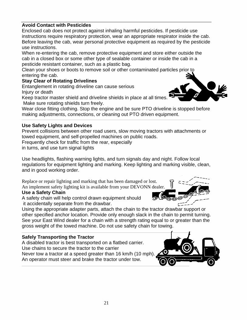
Avoid Contact with Pesticides Enclosed cab does not protect against inhaling harmful pesticides. If pesticide use instructions require respiratory protection, wear an appropriate respirator inside the cab. Before leaving the cab, wear personal protective equipment as required by the pesticide use instructions. When re-entering the cab, remove protective equipment and store either outside the cab in a closed box or some other type of sealable container or inside the cab in a pesticide resistant container, such as a plastic bag. Clean your shoes or boots to remove soil or other contaminated particles prior to entering the cab. Stay Clear of Rotating Drivelines Entanglement in rotating driveline can cause serious Injury or death Keep tractor master shield and driveline shields in place at all times. Make sure rotating shields turn freely.
Wear close fitting clothing. Stop the engine and be sure PTO driveline is stopped before making adjustments, connections, or cleaning out PTO driven equipment.
Use Safety Lights and Devices Prevent collisions between other road users, slow moving tractors with attachments or towed equipment, and self-propelled machines on public roads. Frequently check for traffic from the rear, especially in turns, and use turn signal lights
Use headlights, flashing warning lights, and turn signals day and night. Follow local regulations for equipment lighting and marking. Keep lighting and marking visible, clean, and in good working order.
Replace or repair lighting and marking that has been damaged or lost. An implement safety lighting kit is available from your DEVONN dealer. Use a Safety Chain A safety chain will help control drawn equipment should it accidentally separate from the drawbar. Using the appropriate adapter parts, attach the chain to the tractor drawbar support or other specified anchor location. Provide only enough slack in the chain to permit turning. See your East Wind dealer for a chain with a strength rating equal to or greater than the gross weight of the towed machine. Do not use safety chain for towing.
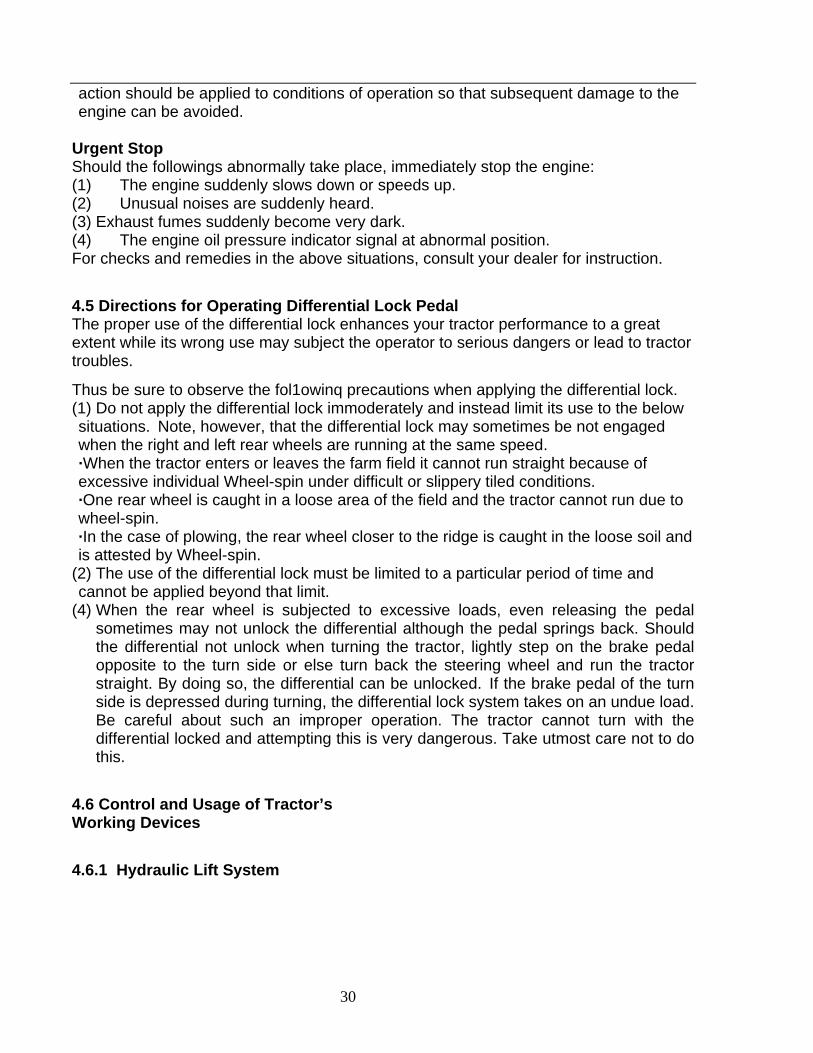
Safely Transporting the Tractor A disabled tractor is best transported on a flatbed carrier. Use chains to secure the tractor to the carrier Never tow a tractor at a speed greater than 16 km/h (10 mph). An operator must steer and brake the tractor under tow.

21
Tow Loads Safely Stopping distance increases with speed and weight of towed loads, and on slopes. Towed loads with or without brakes that are too heavy for the tractor or are towed too fast can cause loss of control. Consider the total weight of the equipment and its load. Observe these recommended maximum road speeds, or local speed limits which may be lower: ·If towed equipment does not have brakes, do not travel more than 20 km/h (12.5 mph) and do not tow loads more than 1.5 times the tractor weigh. ·If towed equipment has brakes, do not travel more than 30 km/h (25 mph) and do not tow loads more than 3 times the tractor weight.
Ensure the load does not exceed the recommended weight ratio. Add ballast to recommended maximum for tractor, lighten the load, or get a heavier towing unit. The tractor must be heavy and powerful enough with adequate braking power for the towed load. Use additional caution when towing loads under adverse surface conditions, when turning, and on inclines.
Keep ROPS Installed Properly
Make certain all parts are reinstalled correctly if the roll-over protective structure (ROPS) is loosened or removed for any reason. Tighten mounting bolts to proper torque.
The protection offered by ROPS will be impaired if ROPS is subjected to structural damage, is involved in an overturn incident, or is in any way altered by welding, bending, drilling, or cutting. A damaged ROPS should be replaced, not reused.
Practice Safe Maintenance Understand service procedure before doing work Keep area clean and dry.
Never lubricate, service, or adjust machine while it is moving. Keep hands, feet, and clothing from power-driven parts. Disengage all power and operate controls to relieve pressure. Lower equipment to the ground. Stop the engine. Remove the key. Allow machine to cool.
Securely support any machine elements that must be raised for service work.
Keep all parts in good condition and properly installed. Fix damage immediately. Replace worn or broken parts. Remove any buildup of grease, oil, or debris.
Disconnect battery ground cable (-) before making adjustments on electrical systems or welding on machine. On towed implements, disconnect wiring harnesses from tractor before servicing electrical system components or welding on machine. Service Cooling System Safely Explosive release of fluids from pressurized cooling system can cause serious burns Add make-up coolant through the external container not directly to the radiator If radiator cap must be removed, do not remove when engine is hot. Shut engine off and wait until cap is cool enough to touch with bare hands. Slowly loosen cap to first stop to relieve pressure before removing completely

21
Service Tractor Safely Do not service the tractor while it is in motion or while the engine is running. When servicing front-wheel-drive-equipped tractor with rear wheels supported off ground and rotating wheels by engine power, always support front wheels in a similar manner. Engaging front-wheel drive will pull rear wheels off support if front wheels are not raised.
Tighten wheel hardware to correct torque as specified in Wheels, Tires and Tread Section. Torque at intervals shown in Break-In Period and Lubrication and Maintenance Sections, to ensure that wheel hardware does not loosen. Reinstall protective covers removed during service.
Support Machine Properly Always lower the attachment or implement to the ground before you work on the machine. If you must work on a lifted machine or attachment, securely support the machine or attachment. If left in a raised position, hydraulically supported devices can settle or leak down.
Do not support the machine on cinder blocks, hollow tiles, or props that may crumble under continuous load. Do not work under a machine that is supported solely by a jack.
Follow recommended procedures in this manual.
When implements or attachments are used with a tractor, always follow safety precautions listed in the implement operator's manual.
Remove Paint before Welding or Heating Avoid potentially toxic fumes and dust.
Hazardous fumes can be generated when paint is heated by welding, soldering, or using a torch.
Do all work outside or in a well ventilated area. Dispose of paint and solvent properly.
Remove paint before welding or heating: lf you sand or grind paint, avoid breathing the dust. Wear an approved respirator. ·lf you use solvent or paint stripper, remove stripper with soap and water before welding. Remove solvent or paint stripper containers and other flammable material from area. Allow fumes to disperse at least 15 minutes before welding or heating.
Avoid Heating near Pressurized Fluid Lines Flammable spray can be generated by heating near pressurized fluid lines, resulting in severe burns to yourself and bystanders. Do not heat by welding, soldering, or using a torch near pressurized fluid lines or other flammable materials. Pressurized lines can be accidentally cut when heat goes beyond the Immediate flame area.

21
Store Attachments Safely Stored attachments such as dual wheels, cage wheels, and loaders can fall and cause serious injury or death.
Securely store attachments and implements to prevent falling. Keep playing children and bystanders away from storage area. Prevent Acid Burns Sulfuric acid in battery electrolyte is poisonous. It is strong enough to burn skin, eat holes in clothing, and cause blindness if splashed into eyes.
Avoid the hazard by:
1. Filling batteries in a well-ventilated area. 2. Wearing eye protection and rubber gloves. 3. Avoiding breathing fumes when electrolyte is added. 4. Avoiding spilling or dripping electrolyte. 5. Use proper jump start procedure.
If you spill acid on yourself: 1. Flush your skin with water. 2. Apply baking soda or lime to help neutralize the acid. 3. Flush your eyes with water for 15—30 minutes. 4. Get medical attention immediately. If acid is swallowed: 1. Do not induce vomiting. 2. Drink large amounts of water or milk, but do not exceed 2 L (2 quarts). 3. Get medical attention immediately.
Service Tires Safely Explosive separation of a tire and rim parts can cause serious injury or death.
Do not attempt to mount a tire unless you have the proper equipment and experience to perform the job.
Always maintain the correct tire pressure. Do not inflate the tires above the recommended pressure. Never weld or heat a wheel and tire assembly. The heat can cause an increase in air pressure resulting in a tire explosion. Welding can structurally weaken or deform the wheel. When inflating tires, use a clip—on chuck and extension hose long enough to allow you to stand to one side and NOT in front of or over the tire assembly. Use a safety cage if available. Check wheels for low pressure, cuts, bubbles, damaged rims or missing lug bolts and nuts.

21
Dispose of Waste Properly Improperly disposing of waste can threaten the environment and ecology. Potentially harmful waste used with equipment includes such items as oil, fuel, coolant, brake fluid, filters, and batteries.
Use leak proof containers when draining fluids. Do not use food or beverage containers that may mislead someone into drinking from them.
Do not pour waste onto the ground, down a drain, or into any water source..
Inquire on the proper way to recycle or dispose of waste from your local environmental or recycling center, or from your DEVONN dealer
1. Requesting For Dealers Service
Your dealer is interested in your new tractor and has the desire to help you get the most value from it. After reading this manual thoroughly, you will find that you can do many of the regular service jobs quickly and easily.
However, when in need of parts or major service, be sure to see your DEVONN dealer.
When in need of parts, be prepared to give your dealer both the tractor and engine serial numbers.
The tractor serial number is located on the frame right side and lift case up side. The engine serial number is located on the engine crankcase, right side.
Locate the serial numbers now and record them in the space provided.
Tractor Serial No----- Engine Serial No----- Date of purchase----- (To be filled in by purchaser)
Instrument Panel And Controls
17
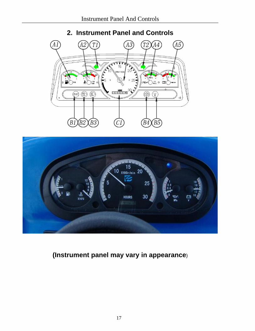
2. Instrument Panel and Controls
(Instrument panel may vary in appearance)

Instrument Panel And Controls
2-5
2.1 Indication Items A1 – Oil Meter A2 – Coolant Temperature Meter A3 – Rotation Speed Meter A4 – Oil Pressure Meter A5 – Voltage Meter B1 – Night Light
B2 –Head Lamp on Full Beam B3 – Dipped Head Lamp B4 – Parking Flash B5 – Voltage Indicator C1 – Hour Meter T1 – Left Turn Signal T2 – Right Turn Signal
2.2 Switches
Key Switch
Inserting the key and turning it one click to the right switch on the electrical circuit and lights up the fuel gauge, engine oil pressure indicator and voltage meter. Depress the clutch pedal and disengage the clutch. Next, turning the key left activates preheating coil (ONLY REQUIRED IN COLD CLIMATE), proceeding to preheat the air intake. After 30 seconds, turn the key switch right and the starter motor will start to rotate and the engine will then start. Release the key switch and it will turn to the home position.
TO STOP the engine, turn the KEY to the LEFT
Buttons
A – Left Turn Signal Button B – Right Turn Signal Button C – Flasher Button D – Head Lamp and Tail Lamp Button E – Horn Button F – Parking Flasher Button
Fuses
Opening the fuses case there are the 5-10-20-30 ampere fuses (on the down, back side of the instrument panel) which safeguards the electrical circuit. When the fuse(s) is blown, examine the causes of the over-current, eliminate the trouble and replace with a new

Instrument Panel And Controls
19
fuse. After that, ensure normal amperage. Spare fuses are available from your DEVONN dealer.
2.3 Controls Accelerator Rod and Pedal Moving the hand accelerator rod backward speeds up the engine and moving it forward slows down the engine. In addition, the engine is speeded up by stepping on the accelerator Pedal with the hand accelerator rod left in the forward position.
Hydraulic Control Lever Operating the hydraulic control lever actuates the hydraulic lift arm, which controls the elevation of the tractor implement. Moving the lever down
lowers the implement and moving it up raises the implement. When the implement reaches the upper or
lower limit the lever automatically returns to the neutral position. In addition, when the lever is brought to the neutral position while the implement is moving up or down, the implement stops and remains at that level.
Main Gear Shift Lever and Shuttle
Shift Handle
There are 8 forward speed changes and 8 reverse speed changes by combined operation of the main gear shift lever, high-low gear shift lever and the shuttle shift handle.
There are 4 positions for the main gear shift lever and 2 positions for the high-low gear shift lever. Combined operation of both speed control lever makes possible 8 forward speed changes. Specifically, 4 forward speeds are achieved with the high-low gear shift lever set at LOW while 5th to 8th
forward speed are achieved with the high-low gear shift lever set at HIGH.
By controlling the shuttle shift handle the tractor forward and reverse can get changed conveniently.

Instrument Panel And Controls
20
PTO Speed Change Lever PTO shaft speed operates in two speeds of 1) 540 rpm and 2) 1000 rpm. To engage PTO depress clutch pedal to the end, move lever forward for 540 rpm or backward for 1000 rpm. Neutral position is in the middle.
Caution: When operating implements ALWAYS
use 540 rpm, only use 1000 rpm when specified by implement manufacture.
Front Wheel Drive Lever
The front wheel drive lever is used in the event that greater traction power is required on a slope or a wet field or that the tractor must be prevented from lunging during rotary-tilling hard soil.
Move lever backward to engage the front wheels - 4 wheel drive.
Caution: Only use 4WD when required, operating tractor full time in 4WD on hard surface will cause damage.

Instrument Panel And Controls
21
Clutch Pedal
Fully depressing the pedal disengages the clutch off the power transmission.
Caution:
a. The clutch pedal must be released slowly when operating tractor.
b. Be sure to release the clutch pedal completely, while the tractor in motion
Safety Precautions:
Whenever changing gears, be sure to use the clutch pedal.
Brake Pedals (Right and Left)
The right and left brake pedals function the brake of rear wheels independently.
Safety Precaution: When operating tractor, be sure to interlock the right and left pedals as illustrated above. Only use independent pedals in low range when required.
Parking Brake Lever
Interlock the right and left brake pedals, step on the pedals and pull the parking brake lever. This procedure locks the parking brake latch on the slots of the brake pedal. To release the parking brake, step on the brake pedals again, turn the lever to normal position.
Instrument Panel And Controls
22
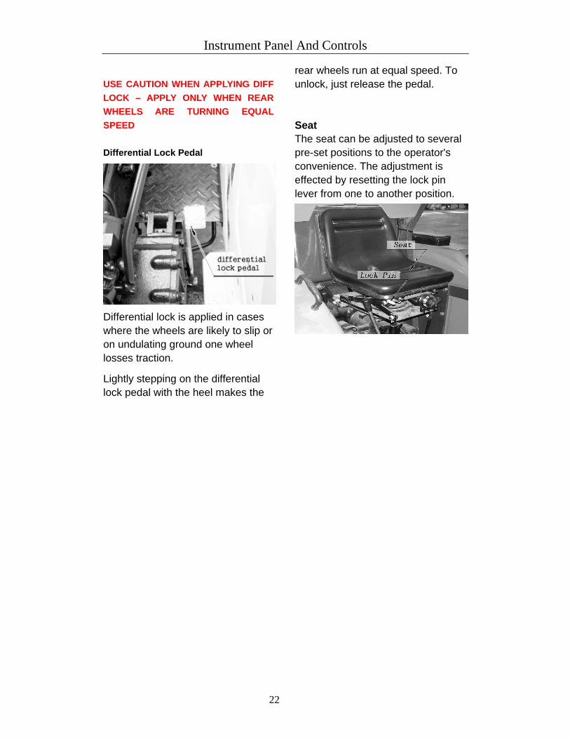
USE CAUTION WHEN APPLYING DIFF
LOCK – APPLY ONLY WHEN REAR WHEELS ARE TURNING EQUAL
SPEED
Differential Lock Pedal
Differential lock is applied in cases where the wheels are likely to slip or on undulating ground one wheel losses traction.
Lightly stepping on the differential lock pedal with the heel makes the
rear wheels run at equal speed. To unlock, just release the pedal.
Seat The seat can be adjusted to several pre-set positions to the operator's convenience. The adjustment is effected by resetting the lock pin lever from one to another position.

Running-in of the tractor
23
3. Running-in of the tractor
In order to prolong the service life of
tractors, it is essential to do the running-in
of a new tractor (or the one right after
major overhauling) before putting it into
service. The running-in improves the
condition of all the running fits and pairing
surfaces so as to avoid premature
failures.
3.1 Running-in of engine without load
3.1.1 Please read carefully the engine operation manual before starting the engine.
3.1.1 After starting, let the engine run at the medium or low speed, and then gradually speed it up after water and oil temperature rises. It is to be avoided to run the engine at high speed right after starting. Check whether there is any water, oil and air leakage and whether all instruments and indicators work well while the engine runs for heating-up.
3.1.2 Let the engine run for 5 minutes at maximum speed and observe engine’s working status, the total running-in time of engine without load needs 20~30 minutes.
3.2 Running-in of the tractor
without load
3.2.1 Drive the tractor away from rest according to regulations set forth in this operation manual.
3.2.2 Run the tractor at every forward and reverse gear for half an hour respectively. And do the steering operation at medium and low speeds, properly use either LH brake or RH brake in concert with the steering operation, try emergency braking when tractor running at gear VII or VIII with limited throttle and engage the front wheel drive axle.
3.2.3 Engage the PTO shaft, and operate the hydraulic lifting system repeatedly so as to do the running-in of hydraulic system and PTO shaft.
3.3 Running-in of the tractor with load
3.3.1 When operating the tractor with load for the running-in, the load must be added from the light to heavy and gears be changed gradually from the low to high, meanwhile, do steering operation time and again, the time period for running-in with load amounts to 50 hours in total. The running-in criteria are as follows:
Running-in time for every gear (hr.)
Running-in stage
Hitching force (kg)
Total time at various stage
(hr.) 1 130 2 2 4 4 4 4 20 2 250 2 2 5 5 14 3 400 2 2 6 6 16

Running-in of the tractor
24
Points for attention:Engage the front drive axle for the running-in at every gear except Gear 4.

Running-in of the tractor
28
3.3.2 Running-in of hydraulic lift system with load is to be done with a plow mounted, which should be done before the running-in of transmission system, repeat the lift and release operation for at least 20 times while engine is working at the rated speed.
3.3.3 If the above running-in condition could not be satisfied, then light-load operation can be used as a substitute. For example, shallow -tillage in the even soil with low resistance or hauling operation with 1.5 ton of cargo loaded in the trailer may also be adopted for running in the tractor.
Points for attention: Observe the working conditions of all the parts and components in every stage of the running-in. If any abnormal condition occurs in the running-in, fix it up immediately. While running in the transmission system, PTO shaft should be “Disengaged”.
3.4 Work after the running-in
3.4.1 Drain off hot lubricant in all the sumps of chassis immediately, add some clean diesel oil, jack up one of rear wheels and one front wheel on the same side carefully, start the engine, run the tractor for 2 minutes at Gear I with low throttle, meanwhile, operate the hydraulic lift system for several times, then stop the engine, drain off the
washing oil while the machine is still hot, and fill up with fresh oil at last.
3.4.2 Drain off the lube oil from engine sump while the engine is still hot, add clean diesel oil to clean the sump and oil filter, replace filter element and then fill up with fresh lube oil.
3.4.3 Cleaning fuel filter & air filter 3.4.3.1Cleaning fuel filter should not
be done in the field but in a clean place. a. Close the fuel filter cock. b. Remove the fuel filter and take out the element and dip it in the kerosene to rinse.
c. Please pay close attention not to run the engine when filter removed.
3.4.3.2 Cleaning air filter Shock the filter element lightly, blow the
compressed air from inside, the
pressure of compressed air must be
under 588 kPa.
3.4.4 Drain off the cooling water, clean the cooling system with soft water.
3.4.5 Check all the fasteners, tighten any of them if necessary.
3.4.6 Check toe-in of the front wheel, the free travel of brake and clutch pedals, make adjustment if necessary.
3.4.7 Add grease into all the grease nipple

Operating Instructions
26

27
4.1 Pre-start Checks Prior to starting the engine, make pre-start checks according to the service schedule on page 5-1.
4.2 Starting and Stopping Starting (1) Sit down on the operator's seat. (2) Step on the parking brake. (3) Set the main gear shift lever and the P.T.O speed change lever to the neutral position.
(4) Move the hand accelerator rod to the high position. (5) Plug the key into the key and turn it on. (6) Fully step on the clutch pedal and turn the switch key left, waiting for at least 20 seconds until the preheating coil in the intake manifold is fully heated (only required for cold climates). The lower the ambient temperature is, the longer the preheating time is needed. For the necessary preheating time, refer to the table below:
Temperature Preheating Time 32 ºF (0 ºC) 15 - 30 sec 32 to 23 ºF (0 to -5 ºC) 30 – 40 sec
(7) Turn the key switch to the start position and the starter will run and the engine will then start.
(8) Make sure that the engine oil pressure indicator has registered. If the indicator is not working normal, immediately stop the engine and check the lubrication system.
(9) Perform warm-up operations by running the engine at the medium speed. (10) Below -10 C, plug heater in to pre-warm antifreeze for 2 hours. (Optional engine block heater --120V or 240V)
Caution (1) While the engine is running, do not turn the switch key. (2) If the engine does not catch motion 10 seconds after the switch is turned on, wait about 20 seconds more and repeat the procedure above. If the switch key is continuously set to the start position for more than 30 seconds it may lead to the trouble with the starter.
(3) Be sure to perform warm-up operations regardless of the ambient temperature. If the tractor is run before the engine warms up, the engine life is reduced, and the tractor life, in turn, will also be affected.
(4) Don’t use starting fluid; doing so may cause serious damage to the engine.
Safety Precautions: (1) Do not attempt to start the engine in a closed room. Otherwise this will contaminate the air with exhaust, leading to the risk of poisoning.
(2) Make it a habit to start the engine after moving the main gear shift lever and P.T.O speed change lever to the neutral positions then disengaging the clutch. If this procedure is not observed, the tractor may dangerously lunge forward the moment the engine starts.

28
Starting with Low Battery or in Cold Weather (1) Preheating the engine. (2) Turn the decompressor lever clockwise. (3) Depress the clutch pedal all the way and turn the switch key to the starting position, then turn the decompressor lever to the normal position.
Caution: When the ambient temperature is over than 5 ºF (-15 ºC), remove the battery from the tractor and store it somewhere warm until next operation.
Stopping (1) Slow down the engine to less than 1000 rpm by moving the hand accelerator lever
forward and releasing the accelerator pedal. (2) Turn the key switch key left and the engine will stop. (3) Turn the switch off and remove the key.
Caution: Although engine can be stopped by turning the decompressor lever clockwise, this should never be done except in such an emergency case that the engine cannot be stopped by turning the switch key left. Especially, if the decompressor is turned clockwise while the engine is running at high speed, there is the danger that the valve seat may be damaged or the decompression device may develop troubles. For this reason, be absolutely sure not to turn the decompressor when the engine is running except in emergency cases.
4.3 Driving Starting (1) Depress the clutch pedal and disengage clutch. (2) Shift the main and high-low gear shift Levers to the desired speed positions. (3) Shift the shuttle shift handle to the desired forward or reverse positions. (4) Unlock the parking brake. (5) Speed up the engine by pulling the hand accelerator rod backward, or use the foot
throttle. (6) Slowly release the clutch pedal and the tractor will start to move. Caution:
(1) Do not drive the tractor with the parking brake on. (2) Do not drive with your foot on the clutch pedal.
Safety Precautions: (1) Sudden release of the clutch pedal makes the tractor dangerously lunge forward. (2) Be sure to gear shift the tractor by fully stepping on the clutch pedal. (3) Inter-lock the right and left brake pedals before starting. Uneven braking results in a sharp turn which may even turn over the tractor.
(4) Do not allow any person other than the driver to ride on the tractor. (5) Do not drive the tractor close to the edges of ditches or banks which may break under the weight of the tractor, especially when the ground is loose or wet.
(6) When turning the tractor be sure to show down the engine speed and as necessary, throw the high-low gear shift lever to low.
(7) Do not drive the tractor on the road with the implement in motion.

29
(8) After the differentiae Lock has been used be sure to see that it has been released. (9) When going down a slope, apply the engine brake. Stepping only on the brake pedal is dangerous.
Stopping (1) Slow down the engine. (2) Step on both the clutch pedal and brake pedal and the tractors will stop. (3) Throw the main gearshift Lever to the neutral position and release the clutch pedal. (3) Interlock the right and Left brake pedals then apply the parking brake. Safety Precautions: (1) When parking, be sure to apply the parking bake. (2) When parking on a slop, be sure to take added precision against rolling by placing stones or something behind the wheels.
(3) Before getting off the tractor, be sure to stop the engine and lower the implement to the ground to prevent sudden dashing or implement drop.
4.4 Check during driving While driving make the following check to see that all the parts are functioning normally. Cooling water If the temperature of the cooling water rises above 212 ºF (100 ºC) and the vapor and water don't stop running out of the overflow pipe, immediately stop the engine and exercise the following checks and remedies, bearing in mind the safety precautions. (1) Shortage or leakage of the cooling water. (2) Foreign matter on the radiator net and dust and dirt between the radiator fins tube. (3) Slackness of the fan drive belt. (4) For formation in the radiator tube. (5) Unnecessary addition of anti-freeze to the cooling water not in cold weather.
Safety Precaution To remove the radiator cap, wait for about 10 minutes after stopping the engine. Immediate removal of the radiator cap lets the hot water spray out, scalding the operator.
Engine oil Pressure Indicator The pressure indicator signals to the operator whether the engine oil pressure works under the prescribed level or not. If the indicator give the incorrect signal, Immediately stop the engine and check: (1) The level of the engine oil (See page 6-2). (2) The conditions of the lubrication system.
Fuel Be careful for the fuel tank not to run dry. otherwise air may be sucked into the fuel system. Should this happen, the system must be bled. (See page 6-1).
Exhaust Fumes (1) Exhaust fumes are colorless at normal output drive. (2) Exhaust fumes become a little colored when output power develops above the rating, but does not affect the traction. If the exhaust turns dark continuously during driving, this probably indicates an overburden on the engine. In such a case, corrective
30
action should be applied to conditions of operation so that subsequent damage to the engine can be avoided.
Urgent Stop Should the followings abnormally take place, immediately stop the engine: (1) The engine suddenly slows down or speeds up. (2) Unusual noises are suddenly heard. (3) Exhaust fumes suddenly become very dark. (4) The engine oil pressure indicator signal at abnormal position. For checks and remedies in the above situations, consult your dealer for instruction.
4.5 Directions for Operating Differential Lock Pedal The proper use of the differential lock enhances your tractor performance to a great extent while its wrong use may subject the operator to serious dangers or lead to tractor troubles.
Thus be sure to observe the fol1owinq precautions when applying the differential lock. (1) Do not apply the differential lock immoderately and instead limit its use to the below situations. Note, however, that the differential lock may sometimes be not engaged when the right and left rear wheels are running at the same speed. ·When the tractor enters or leaves the farm field it cannot run straight because of excessive individual Wheel-spin under difficult or slippery tiled conditions. ·One rear wheel is caught in a loose area of the field and the tractor cannot run due to wheel-spin. ·In the case of plowing, the rear wheel closer to the ridge is caught in the loose soil and is attested by Wheel-spin.
(2) The use of the differential lock must be limited to a particular period of time and cannot be applied beyond that limit.
(4) When the rear wheel is subjected to excessive loads, even releasing the pedal sometimes may not unlock the differential although the pedal springs back. Should the differential not unlock when turning the tractor, lightly step on the brake pedal opposite to the turn side or else turn back the steering wheel and run the tractor straight. By doing so, the differential can be unlocked. If the brake pedal of the turn side is depressed during turning, the differential lock system takes on an undue load. Be careful about such an improper operation. The tractor cannot turn with the differential locked and attempting this is very dangerous. Take utmost care not to do this.
4.6 Control and Usage of Tractor’s Working Devices
4.6.1 Hydraulic Lift System

31
Fig. 4-1 Hydraulic lift
1. Depth stop block 2. Pin 3. Lift stop block 4. Control handle 5. Hydraulic oil distributor 6. Lock valve 7. External delivery point plug
a. Lifting & lowering the farm implements (see Fig. 4-1). Shift the control handle (4) forward, then the attached implement will be lowered down. Fix the depth stop block (1) at such a suitable position that the pin (2) will just touch the depth stop block (1) when implement is lowered down to the desired working depth, pull back handle (4) to the neutral position quickly, so that the implement will be kept at the preset working depth. When lifting of the implement is needed, just shift the handle (4) backward, the implement will be lifting until pin (2) touches the lift stop block (3), then push the handle to the neutral position. Different lifting height can be obtained if the lift stop block (3) is fixed at different positions.
If working depth needs to be adjusted slightly during working, the control handle can be moved forward or backward a little bit to meet these needs, please note that the handle must be moved to the neutral position right after the slight adjusting is made. If lifting speed needs to be adjusted, just screw down or up a little bit the hand wheel of hydraulic lock valve (6).
b. Farm implement with land-wheel Push the control handle (4) forward to the “Down” position, oil in the distributor
comes back directly to the gearbox (i.e. oil in the hydraulic distributor has the passage to oil-return pipe) and the implement will drop down to the ground by its weight. Then the tilling depth of the implement is to be controlled by its land-wheel.
c. Hydraulic output Dismount plug (7), link a male connector (tapped hole dimension M14×1.5),
screw down the hydraulic locking valve (6) to the lowest position, the pressure oil will be out entirely instead of entering into hydraulic cylinder. Handle (4) controls the external-connected single-action ram, shift backward the handle (4) to deliver oil to the ram and shift forward the handle to release oil from the ram.
Points for attention: (a) Lift the control handle to neutral position immediately after the filling stroke of ram is finished, so as to avoid long time opening of the safety valve.

32
(b) Disassemble the male connector if no external delivery is needed and reassemble the plug. Remember to screw up the locking valve (6) to the highest position, otherwise the hydraulic lift system will not work.
d. Attaching implement to the tractor Back the tractor to let the hitch point of lower link approach to a farm implement,
move back and forth the control handle till the connecting holes of lower links and the hitch pins of the farm implement are in line with each other. Put the hitch pin in either hole and lock it with a locking pin. At last, adjust upper link to a proper length, link it together with the column of implement by a long pin and then lock it with a locking pin.
e. Adjusting the lift linkage Higher working efficiency, lower working resistance and reliable cultivation quality could be expected if the lift linkage and corresponding implements are adjusted correctly. The upper link is for adjusting the fore-and-aft leveling of plow stock and the penetrability of the plowshare. Right & left lifting rods are for adjusting the plow stock’s crosswise leveling. The land-wheel is for plow-depth control if there is one provided. Adjust the land-wheel first at the beginning of plowing, when one plow share has reached the required plowing depth, adjust the upper link to make the plow parallel to the ground surface, then adjust the length of left or right lifting rod to make depth the same of each plow. For the second bout plowing, since right wheels of the tractor get into the furrow, the plowing depth of the right side plow share will get increased all of a sudden, so right lifting rod and the length of the upper link need to be readjusted again in order to get same plowing depth of every share.
Adjustment of the length of the check chain: The check chain limits the deviation between lift linkage and implements. During plowing some deviation (about 5 cm) is needed to assure the plow’s automatic center resetting. But if the deviation is too much, plow will hit rear wheels of the tractor and cause damage. Since no deviation is needed for rototilling, just lock tightly with nuts after adjusting. Connect the two lower links with the check spring after demounting implement so as to avoid their touching the tyres.
Points for attention: (a) NEVER adjust the upper link and left or right lift link to the minimum length at the same time, otherwise the implement will possibly knock at the cabin or the driver when it is rising to the highest position.
(b) To avoid opening the safety valve, Never move further the control handle backward after the implement reaches the highest position and gets neutralized automatically.
(c) Driving away and turning operations of the tractor are prohibited while the attached implement is not yet lifted off the ground.
(d) Make sure the implements fit the tractor well and there is no interference of implements’ lifting or lowering.
(e) Attention must be paid to avoid implements’ running into earth bank or shaking violently, the low speed gear must be used when crossing the fields so as to avoid any damage of the tractor or implements.
4.6.2 Hauling operation with a trailer is mount suspension linkage, mount a drawbar coupling on to the tractor for hitching up with a trailer. a
If the air brake output installations (optional) is ordered together with the tractor, fix the air pump, brake valve and air tank in turn and further fix the drawbar coupling after checking lubricating oil level of the air pump, then hitch the trailer, connect the air brake
33
pipe and start the engine. When the pressure reading of air pressure gauge on the panel reaches 343 kPa, it is ready for hauling operation then. If the pressure can’t reach the required level during working, check over to find out the reason and fix it up. Trailer’s braking torque varies along with the depressed distance of the brake pedal. Brake pedal should be stepped on all the way to the lowest position quickly without any hesitation when in emergency braking. If lower speed is expected only, just throttle down and do slight braking at the same time. For the hauling set equipped with air brake system, trailer’s braking should be initiated a little bit earlier (or at the same time) than does the tractor’s braking, which could be made by turning the adjusting screws on the brakes of both the tractor and trailer.
When transporting with a single-axle trailer hitched, dismount the previously mounted ballast outside the rear wheels of the tractor, so to avoid overload on rear wheels.
4.6.3 Operation of PTO Shaft a. The PTO shaft speed has the combination of 540 and 1000 rpm. It can be realized by shifting the speed-changing lever of the PTO shaft.
b. Input rotational speed of the PTO driven implements must be the same of the PTO shaft’s out put speed, since the improper matching will cause serious premature failure of the tractor and implements, and also affect the farming job quality.
c. Shift the control handle forward to disengage the PTO shaft, dismount drawbar coupling and the PTO shaft guard, then connect PTO shaft with a specific farm implement. The PTO shaft speed of tractor and the required input speed of farm implement should be identical.
d. Fix firmly the tractor and implement if some stationary job is to be done.
34
5.1 Adjustment of the Engine Please refer to the engine operation manual for its adjustment.
5.2 Adjustment of the Clutch
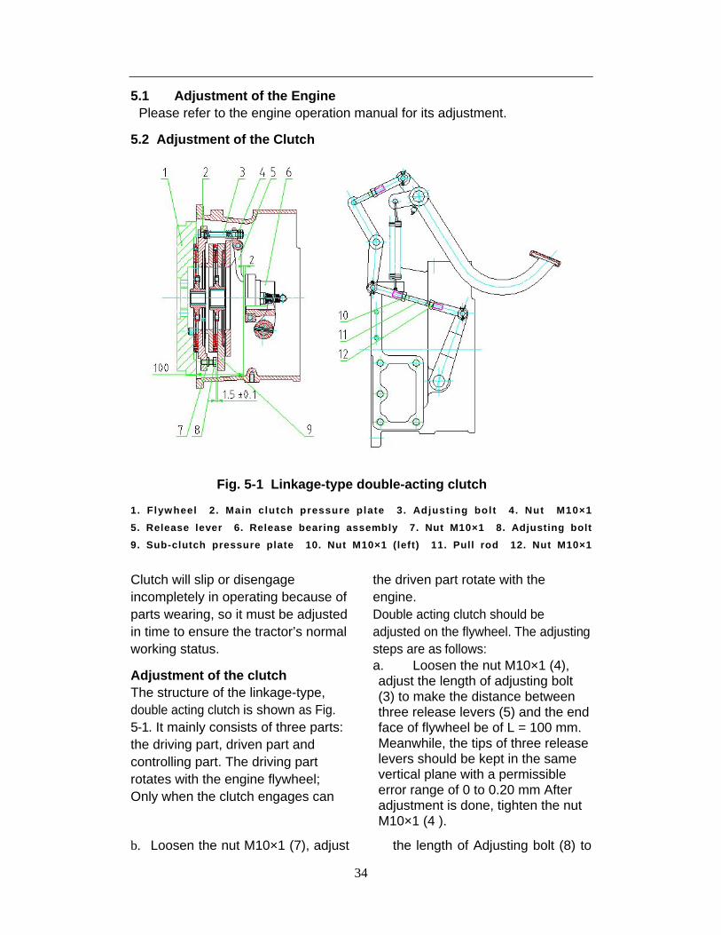
Fig. 5-1 Linkage-type double-acting clutch
1. Flywheel 2. Main clutch pressure plate 3. Adjusting bolt 4. Nut M10×1
5. Release lever 6. Release bearing assembly 7. Nut M10×1 8. Adjusting bolt
9. Sub-clutch pressure plate 10. Nut M10×1 (left) 11. Pull rod 12. Nut M10×1
Clutch will slip or disengage incompletely in operating because of parts wearing, so it must be adjusted in time to ensure the tractor’s normal working status.
Adjustment of the clutch The structure of the linkage-type, double acting clutch is shown as Fig. 5-1. It mainly consists of three parts: the driving part, driven part and controlling part. The driving part rotates with the engine flywheel; Only when the clutch engages can
the driven part rotate with the engine. Double acting clutch should be adjusted on the flywheel. The adjusting steps are as follows: a. Loosen the nut M10×1 (4), adjust the length of adjusting bolt (3) to make the distance between three release levers (5) and the end face of flywheel be of L = 100 mm. Meanwhile, the tips of three release levers should be kept in the same vertical plane with a permissible error range of 0 to 0.20 mm After adjustment is done, tighten the nut M10×1 (4 ).
b. Loosen the nut M10×1 (7), adjust the length of Adjusting bolt (8) to
35
make the distance between the end faces of Adjusting bolt (4 ) and the sub-clutch pressure plate(2) be of 1.5 ± 0.1 mm. After adjustment is done, tighten the nut M10×1 (7).
c. Loosen the nut M10×1 (10 and 12), adjust the length of pull rod (11) until the free travel of pedal reaches 36 ± 2 mm, ensure that the clearance from tips of three
release levers (5) and the release bearing assembly (6) is of 2 ± 0.5 mm, then tighten the nut M10×1 (10 and 12).
After adjustment is done, step on the clutch pedal, the main clutch and sub-clutch should be disengaged in turn; after releasing the pedal, the main clutch and sub-clutch should be engaged smoothly and work reliably.
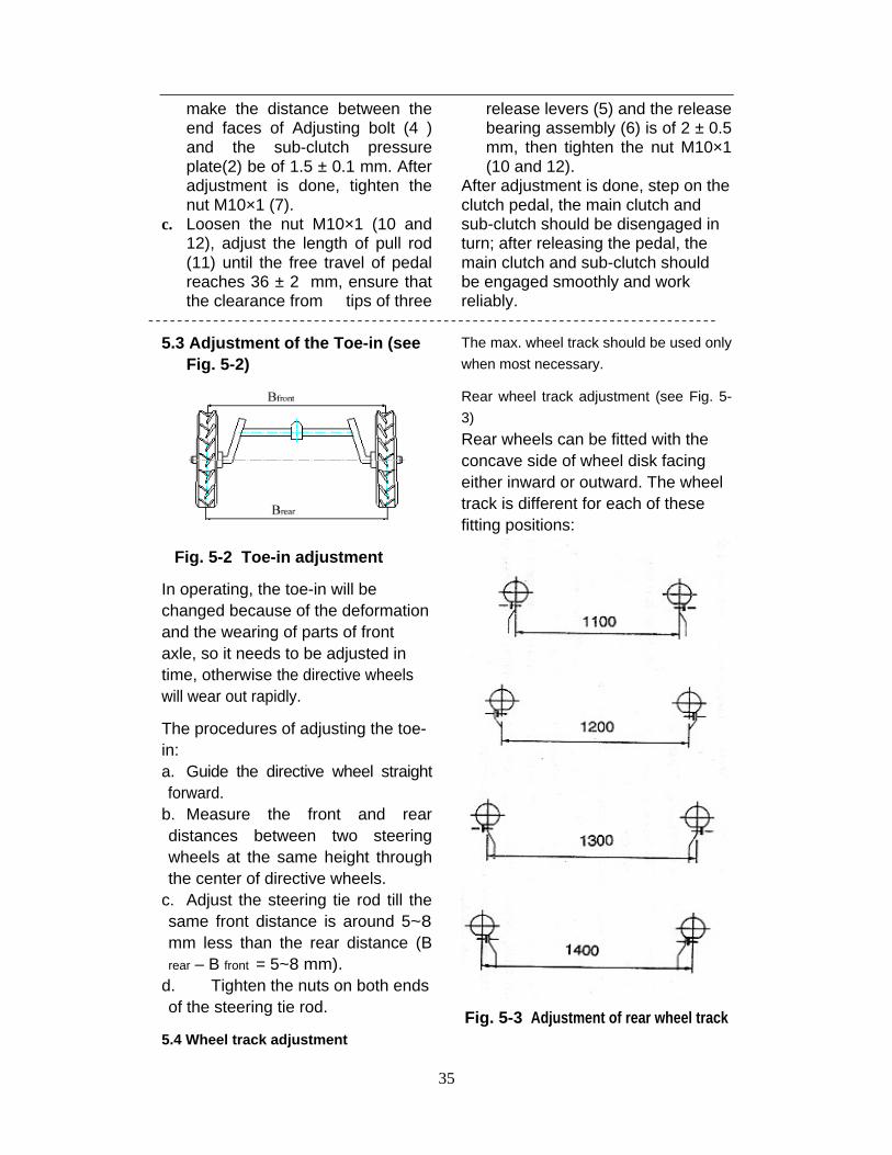
5.3 Adjustment of the Toe-in (see Fig. 5-2)
Fig. 5-2 Toe-in adjustment
In operating, the toe-in will be changed because of the deformation and the wearing of parts of front axle, so it needs to be adjusted in time, otherwise the directive wheels will wear out rapidly.
The procedures of adjusting the toe-in: a. Guide the directive wheel straight forward.
b. Measure the front and rear distances between two steering wheels at the same height through the center of directive wheels.
c. Adjust the steering tie rod till the same front distance is around 5~8 mm less than the rear distance (B rear – B front = 5~8 mm).
d. Tighten the nuts on both ends of the steering tie rod.
5.4 Wheel track adjustment
The max. wheel track should be used only
when most necessary.
Rear wheel track adjustment (see Fig. 5-
3)
Rear wheels can be fitted with the concave side of wheel disk facing either inward or outward. The wheel track is different for each of these fitting positions:
Fig. 5-3 Adjustment of rear wheel track
36
Danger!
When removing the rear wheels, please
take great care and protecting measures,
and use suitable hoist.
Attention!
Make sure that the direction of lugs is determined by facing in the direction of forward travel.
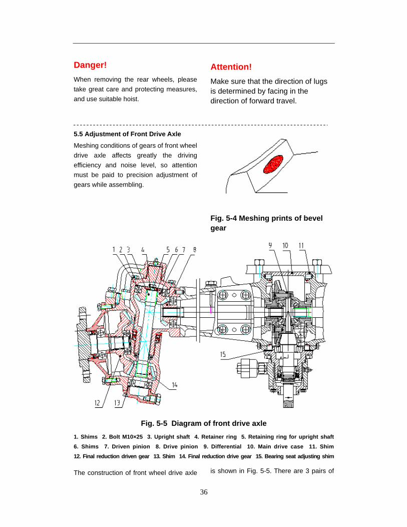
5.5 Adjustment of Front Drive Axle
Meshing conditions of gears of front wheel
drive axle affects greatly the driving
efficiency and noise level, so attention
must be paid to precision adjustment of
gears while assembling.
Fig. 5-4 Meshing prints of bevel gear
Fig. 5-5 Diagram of front drive axle
1. Shims 2. Bolt M10×25 3. Upright shaft 4. Retainer ring 5. Retaining ring for upright shaft
6. Shims 7. Driven pinion 8. Drive pinion 9. Differential 10. Main drive case 11. Shim
12. Final reduction driven gear 13. Shim 14. Final reduction drive gear 15. Bearing seat adjusting shim
The construction of front wheel drive axle is shown in Fig. 5-5. There are 3 pairs of
37
bevel gears in meshing from front center driving bevel pinion to drive shaft in the front drive axle, the gear backlash and meshing zone print (the print should be in the middle of all the teeth face and deflecting to small end of teeth slightly, i.e. short toe contact, see Fig. 5-4) of every pair of gears should be adjusted with great care. a. The meshing of front main drive gears
is adjusted by selecting the shims (15) of
bearing seat and the shims (11) of main
drive case of suitable thickness to ensure
the correct meshing print and the gear
backlash within 0.16~ 0.32 mm.
Meanwhile, keep the pre-stress of
bearing on both ends of the differential
within 100~ 150 N;
b. The meshing of mid gear pair at both ends of front wheel drive axle is adjusted by selecting the
shims (1) of suitable thickness to ensure the gear backlash within 0.16~0.3 mm and the correct meshing print.
c. To ensure the gear backlash of final
drive within 0.16~ 0.3 mm, alter the
thickness of shims (13) for final drive,
meanwhile, keep the correct meshing
print.
d. The clearance of 0.1 0.5 mm between the lower-face of the Retainer ring (4) of the upright shaft (3) at either end and the upper-face of driven pinion (7) is obtained by selecting and using the shims (6) of suitable thicknes.
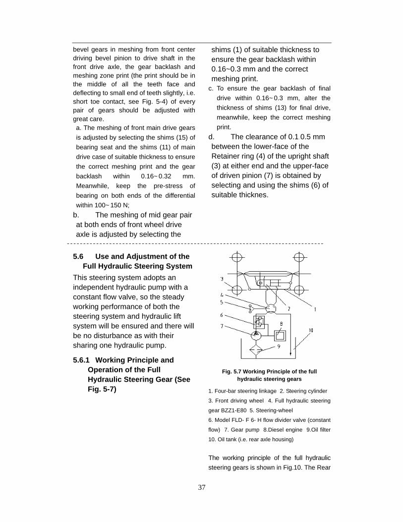
5.6 Use and Adjustment of the Full Hydraulic Steering System
This steering system adopts an independent hydraulic pump with a constant flow valve, so the steady working performance of both the steering system and hydraulic lift system will be ensured and there will be no disturbance as with their sharing one hydraulic pump.
5.6.1 Working Principle and Operation of the Full Hydraulic Steering Gear (See Fig. 5-7)
Fig. 5.7 Working Principle of the full hydraulic steering gears
1. Four-bar steering linkage 2. Steering cylinder
3. Front driving wheel 4. Full hydraulic steering
gear BZZ1-E80 5. Steering-wheel
6. Model FLD- F 6- H flow divider valve (constant
flow) 7. Gear pump 8.Diesel engine 9.Oil filter
10. Oil tank (i.e. rear axle housing)
The working principle of the full hydraulic
steering gears is shown in Fig.10. The Rear

38
axle housing (10) is also being made use of
as the oil tank of the steering gears. Low-
pressure oil flows into Gear pump (7) on the
Diesel engine (8) through the Ø18 inlet pipe
of the pump, and high pressure oil flows into
the Model FLD-F6-H flow divider valve (6)
through the Ø14 outlet pipe. The steady
high pressure oil flows into the Full hydraulic
steering gears of Model BZZ1-E80 (4) and
actuates the Steering cylinder (2) for
steering action, but the overflow oil comes
back to the gear pump through the oil return
pipe. The Model FLD-F6-H flow divider
valve is adopted for keeping a stable oil
delivery, so as to ensure the steady working
of the hydraulic steering gear.
So long as the engine is running, the
hydraulic steering of the tractor could be
realized just by turning the steering wheel,
and the steering operation shall never be
disturbed by hydraulic lifting operation.
5.6.2 Structure of the full hydraulic steering gear and points for attention
a. The structure of the full hydraulic steering gear is shown in Fig 5.8. The Rotary servo valve, consisting of the Valve element, Valve bush (6) and Valve body (5), controls the flow direction of hydraulic oil. The Stator (7) and Rotor (10) makes up the pair of cycloidal toothing functioning as the flow control valve, which makes the hydraulic oil flow entering into the steering cylinder be in the direct ratio of the turning angle of steering wheel. The Linkage shaft (8) transmits torque.
b. The Full hydraulic steering gears is actuated by the Steering cylinder, therefore, the torque to be applied to the steering wheel is little, normally 4-5 N. m. If the steering operation is found out to be quite heavy or even jamming, please do
not recklessly turn the steering wheel with fierce force but to check thoroughly and fix up the trouble first.
c. In case the tractor is to be dislocated by pushing or hauling while its engine is stopped working, then the steering wheel should be turned fully manually. Please note the torque to be applied to the steering wheel should not be over 250 N. m, and further more, the impulsive and fierce force is prohibited, otherwise, some parts might be damaged.
d. Great care should be taken of the concentricity of the steering shaft and the full hydraulic steering gear while assembling. A clearance of 0.5-1.0 mm should be kept between the steering shaft and steering gears and there also should be a little bit endplay of the steering shaft, so as to avoid any jamming.
e. Check all the screw connection portions and tighten all the bolts and nuts so to avoid any oil leakage of all coupling surfaces and connecting parts, because the oil leakage is strictly forbidden while the full hydraulic steering gears is working.
f. Wash clean all the pipelines of the hydraulic steering gears, strictly prevent them from any contamination while assembling or dismounting them for replacement. The filtration fineness of the filter should be better than 30 µ. The hydraulic oil should be renewed periodically.
g. The oil temperature of the full hydraulic steering system is to be kept within the range of -20 ºC to + 80 ºC, but the normal working temperature of the hydraulic oil should be within + 30 ºC to + 60 ºC.

39
Fig 5.8 Structure of the full hydraulic steering gear
1. Leaf spring 2. Thrust bearing 3. Front cover 4. pin 5. Valve body 6. Valve bush
7. Value clement 8. Linkage shaft 9. Stator 10. Rotor 11. Rear cover 12. Isolation plate
5.7 Adjustment of the Brake
After working for a period of time, the wear and tear of the brake discs enlarges the gaps between brake discs and inner end face of the brake housing and the inner end face of the brake cover as well, which affects the brake performance considerably. Excessive free travel of the brake pedal will even cause the brake ineffective. So the brake should be inspected and adjusted regularly to ensure the safety of the tractor while in traveling. No matter the tractor is new or old, the adjustment should be done in time whenever one of the following brake faults appears:
a. The brake is ineffective due to
excessive free travel of brake pedals;
b. The free travel of the brake pedals is too much little and the brakes are kept in semi-braking status all the time, which makes the brake housing become hot and further quicken the wear and tear of the brake discs;
c. The braking force of left side and right side pedals is different, which causes the brake bias.
Fig. 5-9 shows the structure of disc brake that is consisted of the brake itself and the brake control mechanism. The adjusting methods are as follows:
Methods for adjustment (see Fig. 5-9)

40
Fig. 5-9 Adjustment of disc brake
1. Adjusting rod 2. Rocker arm 3. Self-aligning cushion 4. Nut M12 5. Nut M12
6. Connecting clevis 7. Right brake pedal 8. Left brake pedal 9. Nut M10 10. Pull rod
a. Adjustment of the disc brake under free state
Loosen the outer Locking Nut M12 (5) on the Adjusting rod (1), turn the inner Nut M12 (4) to move longitudinally the Self-aligning cushion (3) and change the mounting angle of the Rocker arm (2). The centerline through the upper and lower holes in the rocker arms should be kept inclining within 6º backward from the plumb line (through the upper hole in rocker arms). Until suitable adjustment is done, tighten the locking Nut M12 (5).
b. Adjustment of the free travel of brake pedals Loosen the locking Nut M10 (9) on the Connecting clevis (6), adjust the position of Pull rod (10) and make the total travel of brake pedals (from their highest position to the point that the brakes are fully braked) within the range of 75-85 mm. After
the adjustment is completed, interlock the left and right brake pedals, make sure that the left and right wheels can be both fully braked while stepping on the brake pedals, then tighten the locking Nut M10 (9).
c. Adjustment for correcting the brake bias When braking in emergency at high speed, the tractor will deviate and the length of tyre prints of left and right wheels will not be the same if the left and right braking force is not adjusted to the same. Loosen the nut M12(4 and 5) on the side with longer tyre print or tighten the nut M12 (4) on the other side with shorter tyre print, and adjust the position of pull rods ,then tighten the locking Nut M12 (5) and Nut M10 (9). Above adjustment repeatedly till the length of both tyre prints reaches about the same and the reliable braking is ensured.
41
Caution!!!!! First test of the brakes will be at Gear 1 and the final test should be at Gear 4.
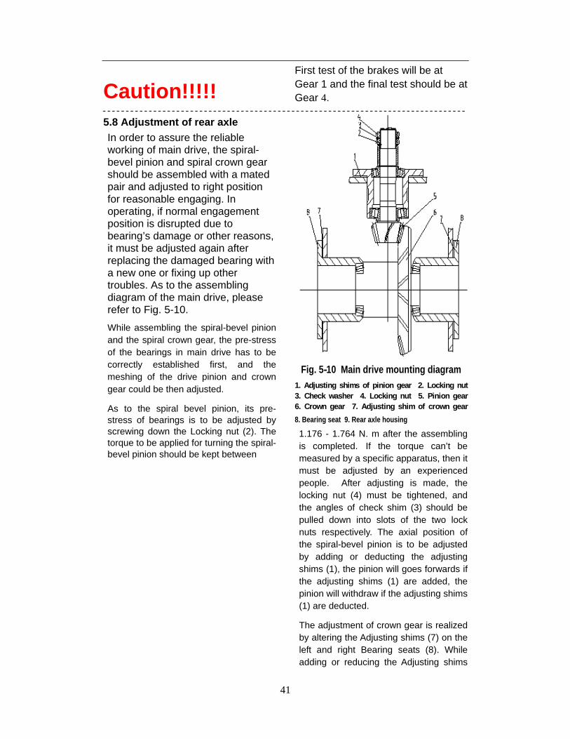
5.8 Adjustment of rear axle In order to assure the reliable working of main drive, the spiral-bevel pinion and spiral crown gear should be assembled with a mated pair and adjusted to right position for reasonable engaging. In operating, if normal engagement position is disrupted due to bearing’s damage or other reasons, it must be adjusted again after replacing the damaged bearing with a new one or fixing up other troubles. As to the assembling diagram of the main drive, please refer to Fig. 5-10.
While assembling the spiral-bevel pinion and the spiral crown gear, the pre-stress of the bearings in main drive has to be correctly established first, and the meshing of the drive pinion and crown gear could be then adjusted.
As to the spiral bevel pinion, its pre-stress of bearings is to be adjusted by screwing down the Locking nut (2). The torque to be applied for turning the spiral-bevel pinion should be kept between
Fig. 5-10 Main drive mounting diagram 1. Adjusting shims of pinion gear 2. Locking nut 3. Check washer 4. Locking nut 5. Pinion gear 6. Crown gear 7. Adjusting shim of crown gear
8. Bearing seat 9. Rear axle housing
1.176 - 1.764 N. m after the assembling is completed. If the torque can’t be measured by a specific apparatus, then it must be adjusted by an experienced people. After adjusting is made, the locking nut (4) must be tightened, and the angles of check shim (3) should be pulled down into slots of the two lock nuts respectively. The axial position of the spiral-bevel pinion is to be adjusted by adding or deducting the adjusting shims (1), the pinion will goes forwards if the adjusting shims (1) are added, the pinion will withdraw if the adjusting shims (1) are deducted.
The adjustment of crown gear is realized by altering the Adjusting shims (7) on the left and right Bearing seats (8). While adding or reducing the Adjusting shims

42
(7) of same thickness to or from either bearing seat, the pre-stress of bearings is alternated but the crown gear position will kept unchanged; if moving the Adjusting shim (7) from one bearing seat to the another one, the crown gear will be shifted towards the side where the Adjusting shim (7) is added but the pre-stress of bearings will remain unchanged. The pre-stress of the spiral crown gear bearings should be kept between 1.2~ 1.8 N. m.
The meshing zone can be measured by smear test of painting the crown gear teeth with some colors such as red lead or Prussian blue. The standard meshing zone should drift to small end slightly (i.e. short toe contact, see Fig. 11). The meshing zone position could be alternated through adding or deducting the adjusting shims of the spiral-bevel pinion and the mated spiral crown gear as well. The print on crown gear shall be taken for evaluation, no matter the print is on convex surface or concave surface. After adjustment having been made, the gear backlash should range from 0.15~ 0.30 mm.
Fig. 5-11 Diagram of meshing zone
5.9 Final Drive System
If chippings from the pinion teeth surface of final drive are found after disassembling the rear axle, then the pinions of left final drive gears and
right one should be exchanged, which may prolong their service life.
5.10 Adjustment of Air Brake Facilities (Optional)
Air brake facilities should be adjusted in two aspects as follows: a. Adjustment of air pump: If the air pressure is found too low while the air pump is working, the exhaust valves’ sealing should be checked up. Clean or grind the exhaust valve if necessary. If the oil gathering in the air tank is found more than 15 ml after the air pump works for 24 hours, then wear-and-tear of piston rings should be checked up, replace them if necessary.
b. Adjustment of air braking timing If the timing of air brake is not correct, then it should be adjusted. If the pull rod of brake valve is shortened, the brake timing becomes earlier, conversely, the brake timing is put off. Usually, trailer’s braking should be initiated a little bit earlier than the tractor’s shoe brakes do.
5.11 Electrical System
1. Battery The tractor is equipped with a 6-QW-80L battery. The voltage of the electrical system is 12 V. When ammeter’s pointer turns to “+”, the battery is in discharging, and when ammeter’s pointer turns to “-”, the battery is in charging. The battery is in charging while the tractor is working in normal condition. We use an AVO meter to check and judge whether the battery is sufficiently charged or not. To avoid unnecessary accident, please DO

43
NOT short circuit by connecting directly the two battery poles (positive and negative) or connecting the positive pole to the tractor’s outer housing for checking current intensity of the battery. When the battery power is insufficient, the starting of tractor is likely to be affected and the battery should be charged in time with external power source.
CHARGING While charging, of importance in this process is the optimum controller voltage of 14.2 V. If the controller voltage is too high, water will be released as a product of electrolysis. This lowers the electrolyte level (fluid
level) as time goes on. If the controller voltage is too low, the battery will not be charged correctly, shortening its service life.
Consistent voltage charging: 16
V. (16.2 V. maximum)
Consistent current charging: Set
the electric current as C20/10 and keep the charging voltage less than 16 V.
Charging finish: Till the hydrometer turns to green or the consistent open circuit voltage is larger than 12.65 V.
2. Fuse Before replacing a blown fuse with a new one of the same current rating, determine the exact causes of the failure and make necessary repairs.
Fuse No. Electric circuits to be protected Current rating
1 General electric circuit 40 A
2 Oil pressure gauge, water thermometer, RPM meter, oil meter 10 A
3 Electronic voltage regulator 10 A
4 Headlamp 25 A
left & right turning indicator lamp & Brake indicator lamp & horn 20 A
5 Marker lamp, Rear working light 20 A

Lubrication and Maintenance of the Tractor
44

Lubrication and Maintenance of the Tractor
45
6. Lubrication and Maintenance of the Tractor 6.1 Oils to be used by the tractor and lubrication 6.1.1 Fuel oil and lubricants for the tractor
Position Temperature range Category of oil Remarks
Above 10 C No. 0 Light diesel 0C -10 C No. -10 Light diesel Fuel tank Below -10C No. -35 Light diesel
Gearbox, rear axle, front drive axle, hydraulic system
All atmospheric temperature
ATF – Automatic transmission fluid
Clutch release bearing
Other grease nipples
All atmospheric temperature
Lithium-based grease
Summer SAE 15W/40 Diesel Oil
Engine sump Winter
10W/30 or 0W/40 Diesel Oil
Lubrication and Maintenance of the Tractor
46
6.1.2 Lubrication positions
Oil inlet: Engine (please refer to the engine operation manual) 1 on right side cover of the steering-gears 1 on upper-cover of the rear axle housing 1 on crankcase of the air pump 1 on left & right sleeves of the front axle
Grease nipples: Water pump bearings of the engine 2 on the turnbuckles of the left & right lifting rod 1 on upper link 2 on the turnbuckles of the left & right check chains 2 on front & rear jaws of steering drag link 2 on left & right jaws of steering tie rod 2 on left & right front wheel hubs 2 on left & right steering arms 1 on oscillating shaft sleeve (two wheeled drive only) 2 on rear pedestal (four wheeled drive only)
2 on left & right steering crank (four wheeled drive only) 1 on clutch operating shaft 1 on brake operating shaft
Oil level inspection points: Dipstick of engine Dipstick on upper cover of rear axle housing Dipstick on left half shaft housing of front wheel drive axle
Oil-level inspection plug on the air pump
side cover
Oil drain plugs on: Bottom of the engine sump Lower-left side of the gearbox Lower-rear side of the rear axle housing Bottom of the air pump Bottom of the oil tank Bottom of front wheel drive housing (four wheeled drive only) Bottom of transfer case housing
6.2 Maintenance of the tractor
6.2.1 Daily maintenance
Engine a. Make sure that the engine lube oil is enough and keep the oil level between the middle notch and upper notch on the dipstick. Oil level beyond the upper notch is NOT permitted. Let the new engines and those that have been stored for a long time run at low speed for 5 to 10 minutes, then check the oil level again and replenish if necessary.
b. Fill up the water tank and diesel tank
with enough cooling water & diesel oil
respectively.
Chassis a. Check and tighten all the external bolts and nuts.
b. Grease the following positions: Left & right hubs of the front wheel, left & right jaws of steering tie rod, left & right steering arms of the front wheel drive axle and bearing of the water pump of engine.
c. Remove the fault of oil, water or air leakage, clean the outer surface if dirt.

Lubrication and Maintenance of the Tractor
47
d. Check tyre pressure, inflate if
necessary.
Electric facilities
a. Checking and cleaning of electrical
wiring and battery cable.
b. Check wiring for chafed or cracked insulation.
c. Check wiring harness clamp. Replace if necessary.
d. Check connectors and terminals for looseness, contamination or overheated connection.
6.2.2 Maintenance after 50 working
hours
Engine After 50 hours’ running-in with light load, the lube oil of the new engine should be changed entirely, including the lube oil in the engine sump and the injection pump. Change the oil filter element. Clean the sump, oil filter and strainer with clean diesel.
Transmission system After the tractor is used for 50 hours, check the free travel of the clutch pedal, and adjust it if necessary.
Lubricate the nipples mentioned above with a grease gun.
6.2.3 Maintenance after every 100 working hours
Engine a. Change oil in the engine sump
and clean the strainer. b. Change engine oil and diesel
filter elements, and clean the cavity of filters.
c. Check the tension of fan belt, adjust it if necessary.
d. Check oil level of injection pump, add oil if necessary.
e. Clean the air filter and change lube oil (if working in a dusty
environment, do it every-shift). Clutch Check the free travel of clutch pedal, make adjustment if necessary.
6.2.4 Maintenance after every 250
working hours
a. Transmission system Check the oil level in rear axle, add oil to prescribed level if necessary.
b. Front axle Check the clearance of front wheel bearings, make adjustment if necessary.
6.2.5 Maintenance after every 500 working hours
a. Check opening pressure and atomization of injector, wash it clean and make adjustment if necessary.
b. Check and fasten cylinder head nuts, adjust valve clearance if necessary.
c. Clean the water scale in cooling system.
d. Replace the lube oil in injection pump.
6.2.6 Maintenance after every 1000 working hours
Engine a. Check the air tightness of valves, lap them if needed.
b. Check the advance angle of injection, make adjustment if necessary.
c. Transmission system Change the lube oil at least one time a year. Attention: Since there is only one small hole as a passage between the gearbox and rear axle housing, after filling up the oil, it is necessary to wait for quite a long time to check the oil level again.

Lubrication and Maintenance of the Tractor
48
Make sure the oil level is acceptable within the upper and lower limits notched on the dipstick. Steering gear Check the grease in steering gear housing, fill it up if necessary.
Front axle \ Front wheel drive axle Clean all parts of front-wheel hub assembly and apply fresh grease.
Electrical system Give a through check to the whole system and change all broken parts.
Note: Maintenance should be carried out at the specified time intervals, which will assure the normal and regular operation of your tractor. Always remember that the check time intervals very much depend on ambient and working conditions, or on your experience. Remember that, in any case, it is better to check too much than too little.
Caution: In case you have any problem or difficulties in operating or maintaining your DEVONN Tractor, please get contact with one of our DEVONN dealers accessible.
6.3 Tractor Storage When your tractor is to be kept in storage for an extended period of time, be sure to take the protective measures hereunder:
The maintenance of engine should be
carried out as per the instructions of
engine manual.
Thoroughly clean the tractor, especially the body parts; brush protective coating on the unpainted metal parts; store the
tractor under cover and in dry and well-ventilated premises.
Ensure that all controls are in neutral or
off or released position (including the
electrical switch and the parking brake).
Do not leave the key in the starter switch.
Make sure that all hydraulic piston rods
are fully withdrawn.
Remove battery, clean battery top and coat terminal clamps and leads with Vaseline, subsequently store the battery in dim and ventilated premises with temperature remaining above 10
Put stands or other supports under the
front axle/front wheel drive axle and rear
axle in order to bear the tractor weight.
With the tractor being propped up, it is
advisable to deflate tires.
Cover the tractor with non-waterproof
canvas.
Drain away thoroughly the water in radiator for passing away the winter season.

49
6.4 Periodic check table
7. Check and Maintenance
Service technician Interval (hr.)
Schedule section
Date Hour meter Name Phone Qualification
50 Hr 6.2.1 & 6.2.2
100 Hr 6.2.1 & 6.2.2 & 6.2.3
150 Hr 6.2.1 & 6.2.2
200 Hr 6.2.1 & 6.2.2 & 6.2.3
250 Hr 6.2.1 & 6.2.2 & 6.2.4
300 Hr 6.2.1 & 6.2.2 & 6.2.3
350 Hr 6.2.1 & 6.2.2
400 Hr 6.2.1 & 6.2.2 & 6.2.3
450 Hr 6.2.1 & 6.2.2
500 Hr 6.2.1 & 6.2.2 & 6.2.3 & 6.2.4 & 6.2.5
600 Hr 6.2.1 & 6.2.2 & 6.2.3
800 Hr 6.2.1 & 6.2.2 & 6.2.3
1000 Hr 6.2.1 & 6.2.2 & 6.2.3 & 6.2.4 & 6.2.5 & 6.2.6
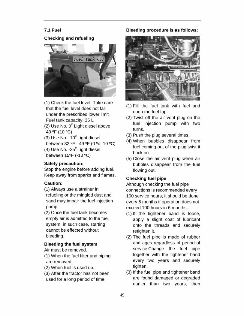
49
7.1 Fuel Checking and refueling
(1) Check the fuel level. Take care that the fuel level does not fall under the prescribed lower limit Fuel tank capacity: 35 L
(2) Use No. 0# Light diesel above 49 ºF (10 ºC)
(3) Use No. -10# Light diesel between 32 ºF - 49 ºF (0 ºc -10 ºC)
(4) Use No. -35# Light diesel between 15ºF (-10 ºC)
Safety precaution: Stop the engine before adding fuel. Keep away from sparks and flames.
Caution: (1) Always use a strainer in refueling or the mingled dust and sand may impair the fuel injection pump
(2) Once the fuel tank becomes empty air is admitted to the fuel system, in such case, starting cannot be effected without bleeding.
Bleeding the fuel system Air must be removed. (1) When the fuel filter and piping are removed.
(2) When fuel is used up. (3) After the tractor has not been used for a long period of time
Bleeding procedure is as follows:
(1) Fill the fuel tank with fuel and open the fuel tap.
(2) Twist off the air vent plug on the fuel injection pump with two turns.
(3) Push the plug several times. (4) When bubbles disappear from
fuel coming out of the plug twist it back on.
(5) Close the air vent plug when air bubbles disappear from the fuel flowing out.
Checking fuel pipe Although checking the fuel pipe connections is recommended every 100 service hours, it should be done every 6 months if operation does not exceed 100 hours in 6 months. (1) If the tightener band is loose,
apply a slight coat of lubricant onto the threads and securely retighten it.
(2) The fuel pipe is made of rubber and ages regardless of period of service Change the fuel pipe together with the tightener band every two years and securely tighten.
(3) If the fuel pipe and tightener band are found damaged or degraded earlier than two years, then

50
change as necessary.
(4) After the fuel pipe and tightener band have been changed, bleed the fuel system.
Safety precautions: (1) Stop the engine when attempting
the check and change as prescribed above.
(2) Do not fail to check the fuel pipe periodically because the impairment of the fuel pipe may lead to dangerous firing.
Caution: When the fuel pipe is disconnected for change, close both ends of the fuel pipe with a piece of clean cloth or paper to prevent any dust and dirt from entering. Entrance of dust and dirt causes malfunction of the fuel injection pump. In addition, particular care must be taken not to admit dust and dirt into the fuel pump.
Replacing the spin on fuel filter When period of operation reaches approx: 100 hours, replace the spin in fuel filter in the following steps: (1) Close the fuel filter tap. (2) Unscrew and remove spin on fuel
filter. (3) Apply small amount of lubricant
grease to rubber seal of fuel filter. (4) Screw firmly new fuel filter to
housing. (5) To bleed the air from fuel system,
open the fuel tap and bleed the system at the injector pump as per 6.1 bleeding the fuel system.
Caution: If dust and dirt enter the fuel, the fuel pump and injection nozzle are subject to quick wear. To shut off this, be sure to change the fuel filter as per 6.2 maintenance of tractor.
7.2 Engine Oil
Oil Level Check and Replenishment (1) Check engine oil either before starting
the engine or 5 minutes or more after
the engine has stopped.
(2) To check the oil level, draw out the oil
level gauge, wipe it clean, replace it,
and draw it out again. Check to see
that the oil level lies between the two
notches
(3) If the level is too low -add new oil to the prescribed level at the oil port
Use Engine Oil
Capacity DF 254G2 5 L DF 304G2 5 L DF 354G2 4.5 L DF 404G2 5L

51
(4) When using an oil of different type, make or viscosity from the previous one, remove all of the old oil. Never mix two different types of oil.
(5) Use the proper Engine Oil according to the ambient temperatures:
Engine Oil Change
(1) To change the used oil, remove the drain plugs (2 plugs) at the bottom left and right of the engine and drain the oil completely. All the used oil can be drained out easily, when the engine is still warm.
(2) Top up with the new oil up to the upper notch on the level stick
Safety precaution: Before changing the oil, be sure to stop the engine.
7.3 Transmission Oil
Draw out the oil gauge on top of the transmission case and wipe off oil. Then, replace it and take it out again to determine the oil level. The appropriate oil level is on the upper notch. If short, replenish through the oil port. ATF – Dexron II or hydraulic dual-purpose oil or equivalent.
Capacity DF 254G2/304G2/354G2/404G2 25 L
Transmission oil change
The oil in the transmission case is also used for the hydraulic drive system.
To drain the transmission case place an oil pan underneath the transmission case and remove the drain plugs at the back of the transmission case.
Temperature range
Category of oil
Summer 15W/40 Diesel oil
Winter 10W/30 or 0W/40 Diesel oil

52
After draining clean drain plug and fill with new gear oil.
Replacing hydraulic oil filter (in changing transmission oil)
As the finest dust in the oil could impair the component parts of the hydraulic system precision-built to withstand high pressure, the suction pipe end is fitted with a spin on hydraulic oil filter.
When changing the transmission oil: replace the spin on hydraulic filter as per 6.2 Maintenance of the Tractor. On reassembly, undertake utmost care not to damage the parts.
7.4 Changing Front Axle Case Oil
Remove the drain plugs, at the bottom of axle case and left & right wheel gear cases, also the filler plug. After draining, replace the drain plugs and fill with new oil.
Type of oil: ATF – (Dexron III) - or Transmission Hydraulic Oil 7.5 Radiator Though the radiator is of rugged construction, wrong handling badly affects the performance of the engine. A full tank of cooling water is enough for one days work. Make it a rule to check the level of the cooling water prior to operation.
Checking, replenishing and changing cooling fluid
Remove the radiator pressure cap and check to see that the water level is just below the port. If short, add water.
Caution: (1) Never replenish with muddy
water or salt water. (2) Securely tighten the pressure
cap. (3) When draining the used cooling
water, open the water drain cock and the pressure cap at the same time. With the pressure cap closed, complete drainage cannot be achieved.
(4) Be sure to close the pressure cap securely. If the cap is loose or improperly closed, water may spill out and water shortage will result.

53
(5) Additives to cooling water Cold season: Anti-freeze solution [at under 32 ºF (0 ºC)]. Normal operation: radiator inhibitor to be used.
Safety precautions: (1) When changing the cooling water
be sure to stop the engine. (2) Do not open the pressure cap
while the engine is running under heavy loads or immediately after the engine has stopped. Otherwise, hot water may spray out, scalding the operator. So let engine cool before opening the cap.
Checking and cleaning radiator for flooding
(1) Adherence of insects, grass, seeds and chaff to the radiator net decreases cooling performance. In such cases, detach the net and wash away the obstacles.
(2) Remove the dust from between the fins and the tube.
(3) Tighten the fan drive belt as necessary.
Checking radiator hose Checking radiator hose tightness is prescribed about every 150 service hours, but every 6 months is all right so long as service duration does not exceed 150 hours in 6 months. (1) If the tightened band is loose,
securely retighten and apply a slight coat of oil.
(2) The radiator hose is made from rubber and tends to age. It must be changed every two years. Together change the tightened band and securely tighten.
Cleaning cooling system The water cooling system should be cleaned on the following occasions:
Every 500 service hours.
When adding Inhibitor/anti-freeze solution.
Anti-freeze
If the cooling water freezes, the engine cylinder and radiator may crack. In cold weather when the temperature drops below 32 ºF (0 ºC), drain out the water or add a proper amount of anti-freeze when the tractor is shut down. (1) There are two types of anti-
freeze solutions, permanent type (PT) and semi-permanent type (SPT). Be sure to use the permanent type.
(2) When anti-freeze is used for the first time, fill and drain clean water two or three times so as to completely clean the inside of the radiator.
(3) Preparations of anti-freeze solutions vary with temperatures under which the engine is operated and do also with suppliers. For this reason, prior to use, ask the store for the instructions as to the proper amount and method of use. Remember that the effective cooling water capacity of the radiator is shown on the table below.
(4) Stir the anti-freeze well in the water and then pour the mixture into the radiator. Use 50/50 mixture
7.6 Tire Pressure Though the tire pressure is factory-set to the prescribed level, it

54
naturally drops slowly in the course of time. Thus check it everyday and inflate as necessary. To inflate the wheel tires use an air compressor or hand pump.
Tire Pressures
DF 254G2 DF 304G2 & 354G2 DF 404G2
220-250 kPa (6.00 -12)
220-250kPa (6.00 -16)
220-250kPa (28×9-15)
Fro
nt
340 kPa (23 x 8.5 -12 industrial)
400 kPa (28x9-15 industrial)
160-220 kPa (7.5-16)
100-150kpa (8.3-24)
100-150 kPa (9.5-24)
220-250 kpa (15-19.5)
Rea
r
310 kPa (14-17.5 NHS industrial)
280 kPa (15-19.5 industrial)
150kp (12.4-24 industrial)
7.7 Air Cleaner
(1) As the air cleaner uses a dry element never apply oil.
(2) Do not let dust build up to more than a half of the dust cup. Detach the dust cup and throw away the dust normally once a week, but everyday if working conditions are especially dusty.
(3) Do not touch the filter element except in cases where cleaning is required.
(4) When cleaning the element, refer to the Instructions attached.
(5) Change the element once yearly or every time the air cleaner is rinsed with water (6 times a year).
Caution: Be sure to refit the dust cup with the arrow (on the rear) upright. If the dust cup is improperly refitted, dust passes by the dust cup and directly adheres to the element, badly affecting the service life.
7.8 Maintenance on free batteries The maintenance-free battery is, as the name implies, totally maintenance-free and has non removable battery cell caps. WATER NEVER NEEDS TO BE ADDED TO THE MAINTENANCE FREE BATTERY. The battery is completely sealed, except for small vent holes in the cover. These vent holes allow what small amount of gases produced in the battery to escape. The special chemical composition inside the battery reduces the production of gas to an extremely small amount at normal charging voltages.
The maintenance-free battery contains a visual test indicator which signals when an adequate charge level exits (green indicator), when charging is required (black), or when replacement is required (white).
To charge the battery connect the battery positive terminal to the charger positive terminal and the negative to the negative, then recharge in the standard fashion.
55
Safety Precaution: (1) Battery gas can explode. Keep
spark and open flame away from the top of the battery, especially when charging the battery.
(2) Be careful not to allow the electrolyte acid to spill on your body or your clothes. The strong electrolyte acid is hazardous and must be treated with care.
(3) When disconnecting the cord from the battery, start with the negative terminal first. When connecting start with the positive terminal first reversing the steps may cause short-circuiting, should a screwdriver touch the terminals.
(4) When connecting the battery, do not reverse the polarities. Connection with reverse polarities causes troubles to the battery and electrical system in the tractor.
(5) Periodic check should be done to make sure that the vent holes should not be plugged up as this can cause an explosion to occur.
(6) Do not charge the battery if the green dot is visible, except immediately following prolonged cranking.
(7) Do not charge the battery if the hydrometer (test indicator) is white.
(8) If the battery feels hot, or if violent gassing or spewing through the vent hole occurs, discontinue charging or reduce charging rate.
(9) Charge the battery only until the green dot appears. Do not overcharge.
(10) When charging batteries there
are fumes created that are potentially explosive. Do not smoke around a charging battery.
7.9 3-Point Linkage Adjustment
Top link Implement tilt can be adjusted by changing the length of the top link. Shortening the top link, for example, tilts the implement head down, thereby enhancing plowing efficiency.
Lift Rod
The lift rod (right) is provided with an adjustment handle for extending or shortening the lift rod. To level the implement, turn the handle.
Sway Bars
The sway bars prevent 3 point hitch mounted implements from swaying and keep the bottom links from rubbing against the inside of the rear tires. The sway bars may be adjusted by turning the sway bars turnbuckle, if the sway chains are too loose, 3 point mounted implements will sway and the bottom links will rub against the inside of the rear tires. To properly adjust sway chain tension, turn the sway bars turnbuckle until it is hand-tight. Once the sway bar is adjusted, tighten the locking nuts against the turnbuckle.

56

57

58
8. Troubles and Trouble-Shooting
8.1 Engine 8.1.1 Diesel Engine Fails to Start
a. Breakdowns of fuel system
Possible causes Fixing methods a. No fuel in fuel tank b. Air in fuel system c. Blockage of fuel system
d. Plunger and barrel of injection pump worn-out
e. Seizing of injector or bad atomization
Add fuel Bleed air, find out the reason and fix it up Replace the fuel filter element with new one and check the fuel delivery pipe Replace with a new one
Replace with a new one or grind it
b. Insufficient compression pressure
Possible causes Fixing methods a. Insufficient valve clearance or
maladjustment of the decompression screw
b. Leakage of valve c. Leakage of cylinder head gasket
d. Wear and tear, sticking or gap lapping of piston rings
Adjust as per regulations
Replace with new one or grind it Replace with a new gasket and fasten cylinder head nuts according to regulations Replace the damaged ones, clean the sticking ones or reassemble them
c. Other causes
Possible causes Fixing methods a. Incorrect advance angle of fuel
and valve timing after reassembling b. Low ambient temperature
c. Wrong lube oil d. Water being in cylinder
Readjust them
Use electrothermic plug or fill hot water into the radiator for preheating Use the engine lube oil as regulated Check and fix break downs
8.1.2 Non Oil Pressure or Abnormal Oil Pressure a. Non or too low the oil pressure
Possible causes Fixing methods a. Too low the oil level b. Oil suction pipe NOT submerged
in lube oil so air comes in the pipe
Replenish Reassemble and check whether it is broken Reassemble or replace it
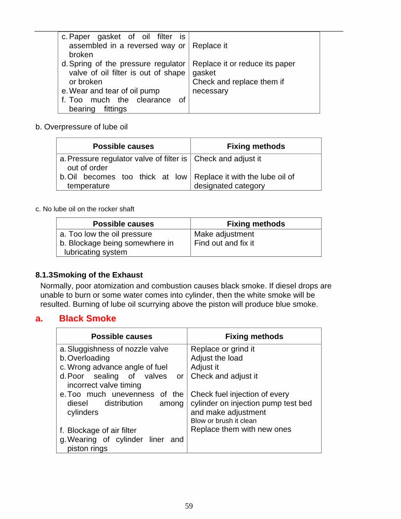
59
c. Paper gasket of oil filter is
assembled in a reversed way or broken
d. Spring of the pressure regulator valve of oil filter is out of shape or broken
e. Wear and tear of oil pump f. Too much the clearance of
bearing fittings
Replace it
Replace it or reduce its paper gasket Check and replace them if necessary
b. Overpressure of lube oil
Possible causes Fixing methods
a. Pressure regulator valve of filter is out of order
b. Oil becomes too thick at low temperature
Check and adjust it
Replace it with the lube oil of designated category
c. No lube oil on the rocker shaft
Possible causes Fixing methods a. Too low the oil pressure b. Blockage being somewhere in
lubricating system
Make adjustment Find out and fix it
8.1.3 Smoking of the Exhaust Normally, poor atomization and combustion causes black smoke. If diesel drops are unable to burn or some water comes into cylinder, then the white smoke will be resulted. Burning of lube oil scurrying above the piston will produce blue smoke.
a. Black Smoke
Possible causes Fixing methods
a. Sluggishness of nozzle valve b. Overloading c. Wrong advance angle of fuel d. Poor sealing of valves or
incorrect valve timing e. Too much unevenness of the
diesel distribution among cylinders
f. Blockage of air filter g. Wearing of cylinder liner and
piston rings
Replace or grind it Adjust the load Adjust it Check and adjust it
Check fuel injection of every cylinder on injection pump test bed and make adjustment Blow or brush it clean Replace them with new ones

60
b. White smoke
Possible causes Fixing methods a. Too low the injection pressure results
in poor atomization with oil drops b. Too low the temperature of cooling water c. Water being in cylinders
Check, adjust or replace the injection pump
Cover the radiator with a cotton pad Check cylinder head gasket and cylinder head, replace the damaged parts with new ones
c. Blue smoke
8.1.4 Insufficient Power Developing Generally, the insufficient supply of oil, air leakage and abnormal combustion will result in such trouble.
Possible causes Fixing methods
a. Blockage of diesel filter b. Poor atomization of nozzle c. Wearing of plunger and barrel
of injection pump d. Deformation of governor
spring, resulting in low rotating speed
e. Incorrect advance angle of fuel
f. Blockage of air filter g. Air leakage of intake and
exhaust valves h. Incorrect valve timing
i. Insufficient compression pressure
Clean it and replace filter element if necessary
Grind or replace it Replace with a new one
Adjust it or replace with a new spring
Adjust Clean it or replace it if necessary Check valve clearance and sealing effectiveness Check and adjust, or replace cam shaft if necessary Replace cylinder liner or piston rings
Possible causes Fixing methods a. The 3rd ring is fitted upside
down b. Wearing of piston rings and
valve guides c. Too much high the lube oil level
Refit it, with the ring face marked “(up)” upward Replace them with new ones
Make it down by draining

61
8.1.4 Abnormal Sound
Possible causes Fixing methods a. Injection timing advanced
too far b. Needle valve of injector
seized
c. Valve clearance is too big, rhythmic valve hammering can be heard clearly
d. Piston touches valves
e. Piston knocks the bottom of cylinder head
f. Valve spring is broken g. Connecting rod bearing or
the small end bush is too loose
h. Too much clearance between piston and cylinder liner
Adjust it
Loosen the high-pressure oil pipe in turn to detect the seized needle valve according to injecting sound (if any one is seized, then it will not give out injection sound), replace the seized one with a new one Adjust it
Valve sinkage is not enough, reamer the valve seat again Replace the cylinder head gasket with a thicker one Replace the broken one with a new one Check and replace the failure parts
Replace with a new piston or a cylinder liner
8.1.6 Serious Vibration Normally, it is caused by uneven working of cylinders, or by incorrect assembling.
Possible causes Fixing methods a. The difference of compression ratio
and fuel distribution among cylinders is considerable
b. Air being in fuel pipes c. Diesel engine is wrongly aligned
in mounting, or fixing bolts are somewhat loose.
d. Piston knocking makes engine rough working
Check and make adjustment
Bleed air Align the engine and fasten the fixing bolts again
Check nozzle of injector and advance angle of fuel, make necessary adjustment
8.1.7 Engine Overheat
Possible causes Fixing methods a. Air leakage of piston rings b. Water coming into engine oil, oil
diluted and deteriorated, or too much high or low the oil level.
c. Too much tight the bearing fitting d. Water pump is broken or its belt is
Replace with new rings Check and replace the engine oil or adjust the oil level by making drainage or replenishment Check and adjust Check and adjust

62
too much loose, resulting in water overheating
e. Temperature regulator is out of work, or insufficient water in tank
f. Cylinder head gasket is broken g. Too much scale in water jacket h. Injector being seized i. Engine overloaded j. Advance angle of fuel is too much
Check and adjust the regulator or replenish water Replace it with a new one Descale the water jacket Replace it with a new one Adjust the load Adjust as per stipulation
8.1.8 High Engine Oil Consumption
Possible causes Fixing methods
a. Engine oil of wrong category being used
b. Piston rings worn out c. Piston ring sticking, oil return hole
in piston ring groove plugged up d. Leakage of rear seal
e. Too much high the oil level
Use the oil as specified
Replace them with new ones Remove carbon deposit and clean the piston Check, replace with new rear seal and its cover Make down the oil level by draining
8.1.9 Rising of Lube Oil Level
Possible causes Fixing methods
a. Water leakage from cylinder head gasket
b. Water leakage from cylinder head or bowl-shaped plug hole in engine block
Check and replace it Repair with epoxy resin or replace with a new plug
8.1.10 Engine Running-away
Possible causes Fixing methods a. Oil delivery control rod of injection pump
seized at the maximum position b. Sliding disc sleeve of governor seized c. Adjusting rod of plunger broken or
escaped from the fork d. Too much lube oil in injection pump e. Too much lube oil entering into cylinder
Check and repair it
Check and repair it Check and repair it
Drain out to the required level Check and fix it
8.1.11 Engine Drifting
Possible causes Fixing methods
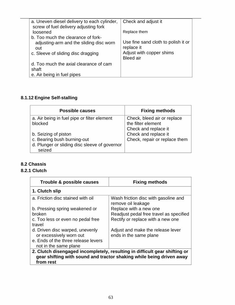
63
a. Uneven diesel delivery to each cylinder, screw of fuel delivery adjusting fork loosened
b. Too much the clearance of fork- adjusting-arm and the sliding disc worn out
c. Sleeve of sliding disc dragging
d. Too much the axial clearance of cam shaft e. Air being in fuel pipes
Check and adjust it
Replace them
Use fine sand cloth to polish it or replace it Adjust with copper shims Bleed air
8.1.12 Engine Self-stalling
Possible causes Fixing methods
a. Air being in fuel pipe or filter element blocked
b. Seizing of piston c. Bearing bush burning-out d. Plunger or sliding disc sleeve of governor
seized
Check, bleed air or replace the filter element Check and replace it Check and replace it Check, repair or replace them
8.2 Chassis 8.2.1 Clutch
Trouble & possible causes Fixing methods
1. Clutch slip
a. Friction disc stained with oil
b. Pressing spring weakened or broken c. Too less or even no pedal free travel d. Driven disc warped, unevenly
or excessively worn out e. Ends of the three release levers
not in the same plane
Wash friction disc with gasoline and remove oil leakage Replace with a new one Readjust pedal free travel as specified
Rectify or replace with a new one
Adjust and make the release lever ends in the same plane
2. Clutch disengaged incompletely, resulting in difficult gear shifting or gear shifting with sound and tractor shaking while being driven away from rest

64
a. Excessive free travel of clutch pedal b. Driven disc excessively warped c. Ends of the three release levers not in
the same plane d. Friction disc broken e. Too tight the friction disc spline
Adjust the pedal free travel as specified Rectify or replace with a new one Adjust the release levers
Replace with a new one Shave the spline of friction disc
3. Vibration and noise in clutch
a. Release lever pressure spring broken b. Release bearing being
insufficiently lubricated or damaged
c. Splined hole of driven disc or clutch splined shaft worn out
d. Clutch front bearing damaged
Replace with a new spring Lubricate it or replace with a new one
Replace the worn out parts with new ones Replace with a new one
8.2.2 Brake
Troubles & possible causes Fixing methods
1. Ineffective brake
a. Brake lining stained with lube oil
b. Brake lining or brake drum worn out
c. Brake cam worn out excessively d. Excessive pedal free travel
Wash brake lining with gasoline and remove oil leakage Replace the worn out parts with new ones Replace with a new brake cam Readjust pedal free travel
2. Brake bias
a. RH and LH braking force different
b. One brake shoe lining stained with oil
Readjust the LH & RH pedal travel to make the braking force same Wash the stained brake shoe lining clean and remove oil leakage
3. Brake disengages incompletely and gets overheated
a. Brake shoe return spring weakened
b. Brake pedals unable to return
c. Too less the pedal free travel
Replace with new springs Check whether the pedal return spring is damaged, or operating shaft is seized and fix up the troubles Readjust the pedal free travel

65
8.2.3 Gearbox
Troubles & possible causes Fixing methods
1. Abnormal sound in gearbox
a. Gearbox bearings or the needle rollers excessively worn out or damaged
b. Abnormal meshing of main drive gears
c. Spline shafts and the splined hole of gears worn out
Check and replace worn out bearings or needle rollers with new ones Examine gear meshing zone print and backlash, adjust them as per stipulations Replace worn out parts with new ones
2. Coming Out Of Gear a. Shift fork excessively worn out or
deformed b. Fork shaft locking spring
weakened c. Tooth profile or spline excessively
worn out
Replace with a new one
Replace with a new one Replace worn out parts with new ones
3. Gearbox overheat a. Too less the clearance of
bearing or gear backlash b. Insufficient or excessive
lubrication oil
c. Lubricating oil deteriorated
Readjust
Add or drain off lubricating oil to the specified level Renew lubricating oil
8.2.4 Traveling and Steering System
Troubles & possible causes Fixing methods
1. Front-wheel wobble
a. Excessive clearance of the front wheel bearing or kingpin bush worn out excessively
b. Wrongly adjusted toe-in c. Ball pin or its seat worn out excessively
d. Pitman arm and ball pin fixing nut become loose
Adjust bearing clearance or replace kingpin bush with a new one
Readjust toe-in Replace ball pin or its seat with a new one Check and tighten the nut
2. Premature wearing of front wheel tires
a. Wrongly adjusted toe-in b. Front wheel pressure insufficient
Readjust toe-in Inflate tires to specified pressure
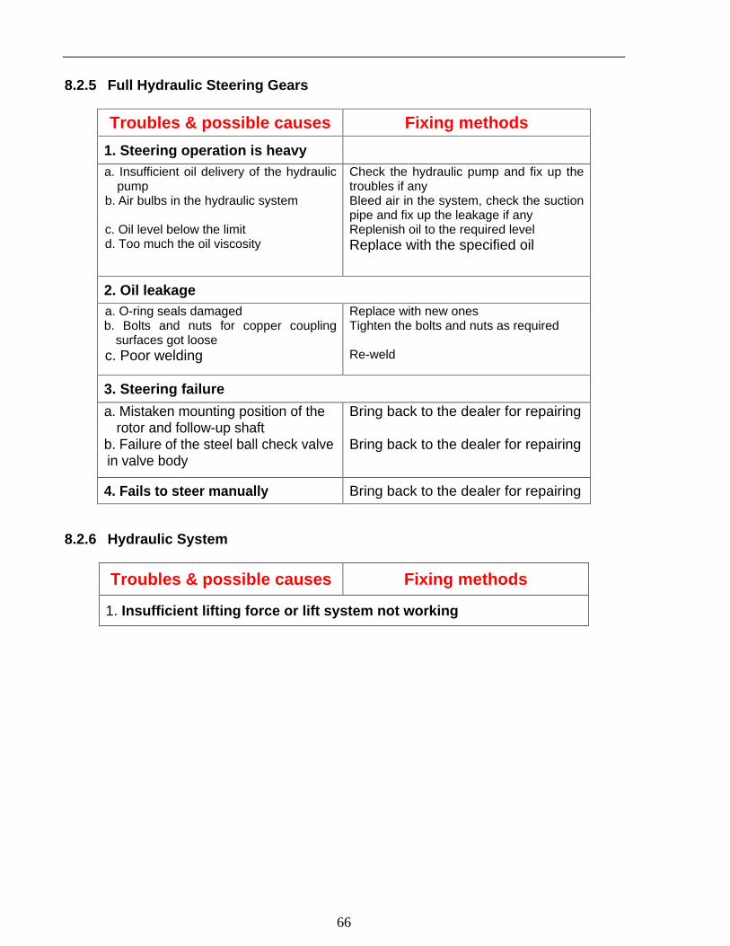
66
8.2.5 Full Hydraulic Steering Gears
Troubles & possible causes Fixing methods
1. Steering operation is heavy a. Insufficient oil delivery of the hydraulic
pump b. Air bulbs in the hydraulic system
c. Oil level below the limit d. Too much the oil viscosity
Check the hydraulic pump and fix up the troubles if any Bleed air in the system, check the suction pipe and fix up the leakage if any Replenish oil to the required level Replace with the specified oil
2. Oil leakage a. O-ring seals damaged b. Bolts and nuts for copper coupling
surfaces got loose c. Poor welding
Replace with new ones Tighten the bolts and nuts as required
Re-weld
3. Steering failure
a. Mistaken mounting position of the rotor and follow-up shaft
b. Failure of the steel ball check valve in valve body
Bring back to the dealer for repairing
Bring back to the dealer for repairing
4. Fails to steer manually Bring back to the dealer for repairing
8.2.6 Hydraulic System
Troubles & possible causes Fixing methods
1. Insufficient lifting force or lift system not working
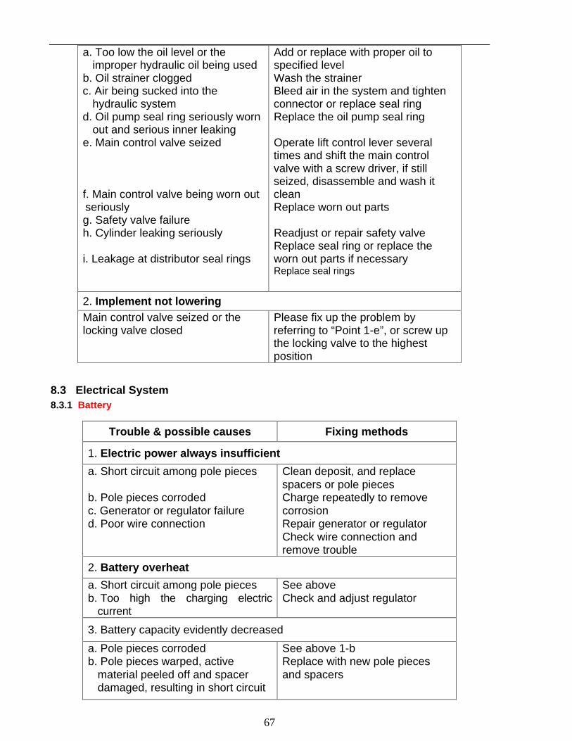
67
a. Too low the oil level or the
improper hydraulic oil being used b. Oil strainer clogged c. Air being sucked into the
hydraulic system d. Oil pump seal ring seriously worn
out and serious inner leaking e. Main control valve seized
f. Main control valve being worn out seriously g. Safety valve failure h. Cylinder leaking seriously
i. Leakage at distributor seal rings
Add or replace with proper oil to specified level Wash the strainer Bleed air in the system and tighten connector or replace seal ring Replace the oil pump seal ring
Operate lift control lever several times and shift the main control valve with a screw driver, if still seized, disassemble and wash it clean Replace worn out parts
Readjust or repair safety valve Replace seal ring or replace the worn out parts if necessary Replace seal rings
2. Implement not lowering Main control valve seized or the locking valve closed
Please fix up the problem by referring to “Point 1-e”, or screw up the locking valve to the highest position
8.3 Electrical System 8.3.1 Battery
Trouble & possible causes Fixing methods
1. Electric power always insufficient
a. Short circuit among pole pieces
b. Pole pieces corroded c. Generator or regulator failure d. Poor wire connection
Clean deposit, and replace spacers or pole pieces Charge repeatedly to remove corrosion Repair generator or regulator Check wire connection and remove trouble
2. Battery overheat
a. Short circuit among pole pieces b. Too high the charging electric
current
See above Check and adjust regulator
3. Battery capacity evidently decreased
a. Pole pieces corroded b. Pole pieces warped, active
material peeled off and spacer damaged, resulting in short circuit
See above 1-b Replace with new pole pieces and spacers

68
8.3.2 Generator
Troubles & possible causes Fixing methods
1. Generator not working
a. Rectifier damaged
b. Carbon brush seized and not in contact with collector ring
c. Broken circuit, short circuit of stator or rotor windings, or poor insulation of earth circuit
Check and replace with a new one if necessary Examine carbon brush size and spring force, repair or replace whichever if necessary Repair or replace with new ones
2. Generator developing insufficient power
a. Generator belt loosened
b. Rectifier damaged c. Poor contact of carbon brushes d. Short circuit of partial
windings of rotor or stator
Adjust belt tension or replace worn out belt with a new one Replace damaged rectifier with a new one
Repair Repair or replace rotor or stator windings with new ones
3. Generator output current unsteady
a. Generator belt loosened
b. Rotor and stator windings being nearly short circuited or broken
c. Carbon brush spring weakened and poor contact of carbon brush
d. Terminals loosened
Adjust belt tension or replace the belt with a new one Repair or replace rotor or stator windings with new ones Repair or replace carbon brush spring with a new one Check and repair
4. Abnormal sound from generator a. Generator wrongly mounted b. Generator bearings damaged c. Rotor hitting stator or other parts
Remount the generator correctly Replace generator bearings with new
ones Check and repair
8.3.3 Starter
Troubles & possible causes Fixing methods
1. Starter not working

69
a. Connecting wire being broken or poor contact of wire connection and switch contacts
b. Fuse blown
c. Battery nearly exhausted d. No contact of the carbon
brushes with commutator e. Inner short circuit of starter
Weld or replace with new connecting wire, clean the oil stain on contacts and tighten all the nuts on connecting points Replace with the fuse of specified current rating Charge battery Check carbon brushes and adjust brush spring force to get good contact Remove short circuit
2. Starter running but unable to start the engine
a. Shaft bushing excessively worn out, causing rotor frictioning with magnetic pole
b. Poor contact of carbon brushes with commutator
c. Commutator surface burnt or with oil stain
d. Welded joint between the armature conductor and commutator broken
e. Poor connection of cable & clamp
f. Solenoid switch contacts ablated g. Battery insufficiently charged
Replace with a new shaft bushing
Wash the commutator surface, shave the brush contacting surface and adjust spring force Grind rough the commutator surface, remove oil stain from commutator surface Re-weld
Tighten clamping nuts to get good connection Repair solenoid switch contacts Charge battery again
3. Starter running continuously after engine being started
a. Solenoid switch contacts ablated
b. Incorrect adjustment of the iron core travel of solenoid switch
See 2-f Readjust the travel
4. Starter begins to run and hits against the end face of ring gear before meshing.
Too less the iron core travel of solenoid switch
Readjust the iron core travel of solenoid switch
Appendix 1 - Moving Locus Diagram of Lift Linkages

70
The lift members’ parameters and motion parameters (mm)
Item The lower link points
A Length of lower link 745
B End span of lower link 600
C Height of farm implement’s column (recommended ) 510
D Length adjusting range of lifting rod 380 - 508
E Connecting position of lifting rod’s lower end with lower link 355
F The ground clearance under the hitch point (while the lower link is at its lowest position) 200
G The ground clearance under the hitch point (while the length of lifting rod is adjusted to 411)
450
H The power lifting range of lower link hitch point (while the length of lifting rod is adjusted to 411)
468
I The ground clearance of hitch point for transportation (while the lifting rod is adjusted to its shortest length of 380)
949
J Length adjusting range of upper link 630 - 760

71

72
Appendix 3 - List of Rubber Oil-seal and O-ring seal
Seq. No.
Standard codes No.
Designation and specifications Qt. Location
1 HG4-692-76 Cased rubber oil seal SD 60×90×12 4 Final Drive
3 HG4-692-76 Cased rubber oil seal W 50×72×7 4 Front wheel drive axle
4 HG4-692-76 Cased rubber oil seal PD 50×72×12 6 4 in Front wheel drive axle
2 in Final drive
5 HG4-692-76 Cased rubber oil seal PG 25×42×10 2 Transfer case
6 HG4-692-76 Cased rubber oil seal SD 35×56×12 1 Front wheel drive axle
7 HG4-692-76 Cased rubber oil seal SD 32×52×12 2 Disc Brake
8 HG4-692-76 Cased rubber oil seal PG 25×42×10 1 Drive shaft (DF-304G2 &
354G2)
9 JB 2600-80 Oil seal SG 35×55×10 1 Gearbox
10 GB 3452.1-92 O-ring seal 10.6×1.8 2 Hydraulic lift
11 GB 3452.1-92 O-ring seal 10.6×2.65 11
1 in rear axle, 1 in hydraulic lift 1 on PTO shaft, 8 in Brake
12 GB 3452.1-92 O-ring seal 11.8×2.65 1 Hydraulic lift
13 GB 3452.1-92 O-ring seal 15×2.65 4 2 in Rear axle
2 in Hydraulic lift
14 GB 3452.1-92 O-ring seal 18×2.65 2 1 in Oil pump
15 GB 3452.1-92 O-ring seal 26.5×2.65 2 Final drive
16 GB 3452.1-82 O-ring seal 30×2.65 1 PTO shaft
17 GB 3452.1-82 O-ring seal 33.5×3.55 1 Rear axle
18 GB 3452.1-92 O-ring seal 38.7×5.3 2 Hydraulic lift
19 GB 3452.1-82 O-ring seal 54.5×3.55 1 Gearbox
20 GB 3452.1-92 O-ring seal 73×3.55 1 Hydraulic lift
21 GB 3452.1-92 O-ring seal 92.5×5.30 1 Hydraulic lift
22 GB 3452.1-92 O-ring seal 103×3.55 2 Final drive
23 GB 3452.1-92 O-ring seal 128×3.55 2 Final drive
24 GB 3452.1-92 O-ring seal 23.6×2.65 1 Front wheel drive axle
25 GB 3452.1-92 O-ring seal 34.5×2.65 2 Front wheel drive axle
26 GB 3452.1-92 O-ring seal 58×2.65 2 Front wheel drive axle
27 GB 3452.1-92 O-ring seal 65×2.65 1 Front wheel drive axle

73
28 GB 3452.1-
92 O-ring seal 69×2.65 1 Front wheel drive axle
29 GB 3452.1-92 O-ring seal 69×3.55 1 Front wheel drive axle
30 GB 3452.1-92 O-ring seal 30×3.55 1 Front wheel drive axle
31 GB 3452.1-92 O-ring seal 48.7×3.55 3 2 on Drive shaft
1 in Front wheel drive axle
32 GB 3452.1-92 O-ring seal 80×2.65 2 1 in Front wheel drive axle
1 in PTO shaft
33 GB 3452.1-92 O-ring seal 85×2.65 1 Front wheel drive axle
34 GB 3452.1-92 O-ring seal 48.7×3.55 1 Drive shaft (DF-304G2 & 354G2)
35 GB 3452.1-92 O-ring seal 90×2.65 2 Front wheel drive axle
36 GB 3452.1-92 O-ring seal 160×3.55 2 Front wheel drive axle
37 GB 3452.1-92 O-ring seal 9×2.65 1 Transfer case
38 GB 3452.1-92 O-ring seal 15×2.65 1 Transfer case
39 GB 3452.1-92 O-ring seal 45×3.55 1 Transfer case
40 GB 13871-92 FB 40×62×8 1 PTO shaft
Appendix 4 - List of Bearings
Seq. No.
Standard code No.
Designation and specifications Qt. Location
1 Release bearing 688713 1 Clutch (release bearing)
2 GB276-89 Ball bearing 106 1 Gearbox 3 GB276-89 Ball bearing 108 1 PTO shaft 4 GB276-89 Ball bearing 111 2 Front wheel drive axle 5 GB276-89 Ball bearing 205 1 Transfer case 6 GB276-89 Ball bearing 206 1 PTO shaft
7 GB276-89 Ball bearing 207 3 1 in Gearbox 2 in Front wheel drive axle
8 GB276-89 Ball bearing 208 6 2 in Front wheel drive axle 4 in Gearbox
9 GB276-89 Ball bearing 209 3 1 on PTO shaft 2 in Front wheel drive axle
10 GB276-89 Ball bearing 304 1 Transfer case
11 GB276-89 Ball bearing 305 3 1 in Gearbox 2 in Front wheel drive axle
12 GB276-89 Ball bearing 307 2 Gearbox 13 GB277-89 Ball bearing 50205 2 Transfer case
14 GB277-89 Ball bearing 50307 3 1 in Gearbox 2 in Final drive,
15 GB298-89 Ball bearing 60205 1 Drive shaft (DF-304G2 & 354G2)
16 GB297-84 Ball bearing 2007114 2 Final drive.
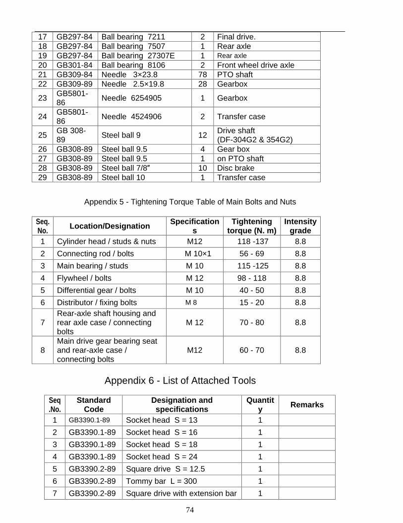
74
17 GB297-84 Ball bearing 7211 2 Final drive. 18 GB297-84 Ball bearing 7507 1 Rear axle 19 GB297-84 Ball bearing 27307E 1 Rear axle 20 GB301-84 Ball bearing 8106 2 Front wheel drive axle 21 GB309-84 Needle 3×23.8 78 PTO shaft 22 GB309-89 Needle 2.5×19.8 28 Gearbox
23 GB5801-86 Needle 6254905 1 Gearbox
24 GB5801-86 Needle 4524906 2 Transfer case
25 GB 308-89 Steel ball 9 12 Drive shaft
(DF-304G2 & 354G2) 26 GB308-89 Steel ball 9.5 4 Gear box 27 GB308-89 Steel ball 9.5 1 on PTO shaft 28 GB308-89 Steel ball 7/8
10 Disc brake 29 GB308-89 Steel ball 10 1 Transfer case
Appendix 5 - Tightening Torque Table of Main Bolts and Nuts
Seq. No. Location/Designation Specification
s Tightening
torque (N. m)
Intensity grade
1 Cylinder head / studs & nuts M12 118 -137 8.8
2 Connecting rod / bolts M 10×1 56 - 69 8.8
3 Main bearing / studs M 10 115 -125 8.8
4 Flywheel / bolts M 12 98 - 118 8.8
5 Differential gear / bolts M 10 40 - 50 8.8
6 Distributor / fixing bolts M 8 15 - 20 8.8
7 Rear-axle shaft housing and rear axle case / connecting bolts
M 12 70 - 80 8.8
8 Main drive gear bearing seat and rear-axle case / connecting bolts
M12 60 - 70 8.8
Appendix 6 - List of Attached Tools
Seq.No.
Standard Code
Designation and specifications
Quantity Remarks
1 GB3390.1-89 Socket head S = 13 1
2 GB3390.1-89 Socket head S = 16 1
3 GB3390.1-89 Socket head S = 18 1
4 GB3390.1-89 Socket head S = 24 1
5 GB3390.2-89 Square drive S = 12.5 1
6 GB3390.2-89 Tommy bar L = 300 1
7 GB3390.2-89 Square drive with extension bar
1

75
S = 12.5 × 12.5 L = 130
8 GB3390.2-89 Open-end spanner 8×10 1
9 GB4440-94 Adjustable spanner 250 mm (10 ) 1
10 GB4593-85 Gas pliers 150 mm ( 6 ) 1
11 GB5356-86 Hexagonal key spanner 6 1
Appendix 7. Packing List
Seq. No. Designation and specifications Quantit
y Remarks
1 DEVONN tractor Model DF254G2/304G2/354G2/404G2 1 To be disposed as
per order
2 Attached tool kit of the tractor 1
3 Operation manual of the tractor of Model DF254G2/304G2/354G2/404G2 1
4 Illustrated parts catalogue of the tractor of Model DF254G2/304G2/354G2/404G2 1
5 Certificate of quality 1
The information contained in this operation manual is of a general introduction only, which is subject to change without notice at any time for technical or other reasons since our product will be under uninterrupted improvements and modifications. Therefore, we would request the users/dealers to give out the manufacturing date and serial No. while placing orders for spare parts and components.
Thanks.