Device manual ProfiNet encoder - ifm · UK Encoder with ProfiNet interface 5 3 General information...
39
Device manual ProfiNet encoder RM30xx 706354/00 06/2013 UK
Transcript of Device manual ProfiNet encoder - ifm · UK Encoder with ProfiNet interface 5 3 General information...
Device manual ProfiNet encoder
RM30xx
7063
54/0
0
06/2
013
UK

Encoder with ProfiNet interface
2
Contents1 Preliminary note � � � � � � � � � � � � � � � � � � � � � � � � � � � � � � � � � � � � � � � � � � � � � � � � � 4
1�1 Symbols used� � � � � � � � � � � � � � � � � � � � � � � � � � � � � � � � � � � � � � � � � � � � � � � 41�2 Warning signs used � � � � � � � � � � � � � � � � � � � � � � � � � � � � � � � � � � � � � � � � � � 41�3 Notes on this document � � � � � � � � � � � � � � � � � � � � � � � � � � � � � � � � � � � � � � � 4
2 Safety instructions � � � � � � � � � � � � � � � � � � � � � � � � � � � � � � � � � � � � � � � � � � � � � � � 43 General information � � � � � � � � � � � � � � � � � � � � � � � � � � � � � � � � � � � � � � � � � � � � � � 5
3�1 Absolute encoder � � � � � � � � � � � � � � � � � � � � � � � � � � � � � � � � � � � � � � � � � � � � 53�2 ProfiNet � � � � � � � � � � � � � � � � � � � � � � � � � � � � � � � � � � � � � � � � � � � � � � � � � � � 5
4 Functions and features � � � � � � � � � � � � � � � � � � � � � � � � � � � � � � � � � � � � � � � � � � � � 65 Electrical connection� � � � � � � � � � � � � � � � � � � � � � � � � � � � � � � � � � � � � � � � � � � � � � 6
5�1 Ethernet and power supply� � � � � � � � � � � � � � � � � � � � � � � � � � � � � � � � � � � � � 65�2 Ethernet cables � � � � � � � � � � � � � � � � � � � � � � � � � � � � � � � � � � � � � � � � � � � � � 7
5�2�1 RJ45 – M12 crossed � � � � � � � � � � � � � � � � � � � � � � � � � � � � � � � � � � � � � 75�2�2 RJ45 – M12 straight� � � � � � � � � � � � � � � � � � � � � � � � � � � � � � � � � � � � � � 75�2�3 M12 – M12 � � � � � � � � � � � � � � � � � � � � � � � � � � � � � � � � � � � � � � � � � � � � 7
6 LED indicators � � � � � � � � � � � � � � � � � � � � � � � � � � � � � � � � � � � � � � � � � � � � � � � � � � 76�1 Legend � � � � � � � � � � � � � � � � � � � � � � � � � � � � � � � � � � � � � � � � � � � � � � � � � � � � 76�2 Status LEDs � � � � � � � � � � � � � � � � � � � � � � � � � � � � � � � � � � � � � � � � � � � � � � � � 8
7 Installation� � � � � � � � � � � � � � � � � � � � � � � � � � � � � � � � � � � � � � � � � � � � � � � � � � � � � � 98 Device configuration � � � � � � � � � � � � � � � � � � � � � � � � � � � � � � � � � � � � � � � � � � � � � 10
8�1 Standardisation � � � � � � � � � � � � � � � � � � � � � � � � � � � � � � � � � � � � � � � � � � � � 108�2 Encoder classes � � � � � � � � � � � � � � � � � � � � � � � � � � � � � � � � � � � � � � � � � � � � 108�3 Encoder functions� � � � � � � � � � � � � � � � � � � � � � � � � � � � � � � � � � � � � � � � � � � 108�4 Signal list for cyclic data transmission � � � � � � � � � � � � � � � � � � � � � � � � � � � �11
8�4�1 Format of position value� � � � � � � � � � � � � � � � � � � � � � � � � � � � � � � � � � �118�4�2 Encoder control word (STW2_ENC) � � � � � � � � � � � � � � � � � � � � � � � � 138�4�3 Encoder status word (ZSW2_ENC) � � � � � � � � � � � � � � � � � � � � � � � � � 148�4�4 Encoder control word (G1_STW)� � � � � � � � � � � � � � � � � � � � � � � � � � � 148�4�5 Encoder status word (G1_ZSW) � � � � � � � � � � � � � � � � � � � � � � � � � � � 15
8�5 Standard and vendor telegrams � � � � � � � � � � � � � � � � � � � � � � � � � � � � � � � � 159 Configuration principle � � � � � � � � � � � � � � � � � � � � � � � � � � � � � � � � � � � � � � � � � � � 17
9�1 Overview of encoder functions � � � � � � � � � � � � � � � � � � � � � � � � � � � � � � � � � 179�2 Encoder functions – Data format � � � � � � � � � � � � � � � � � � � � � � � � � � � � � � � 179�3 Parameters for acyclic data transmission� � � � � � � � � � � � � � � � � � � � � � � � � 19
9�3�1 Standard parameters � � � � � � � � � � � � � � � � � � � � � � � � � � � � � � � � � � � � 209�3�2 Device parameters� � � � � � � � � � � � � � � � � � � � � � � � � � � � � � � � � � � � � � 209�3�3 Vendor parameters � � � � � � � � � � � � � � � � � � � � � � � � � � � � � � � � � � � � � 20
9�4 Supported parameters � � � � � � � � � � � � � � � � � � � � � � � � � � � � � � � � � � � � � � � 209�5 Encoder function description � � � � � � � � � � � � � � � � � � � � � � � � � � � � � � � � � � 22
9�5�1 Code sequence � � � � � � � � � � � � � � � � � � � � � � � � � � � � � � � � � � � � � � � � 239�5�2 Class 4 functionality � � � � � � � � � � � � � � � � � � � � � � � � � � � � � � � � � � � � � 23

UK
Encoder with ProfiNet interface
3
9�5�3 Preset control for G1_XIST1 � � � � � � � � � � � � � � � � � � � � � � � � � � � � � � 239�5�4 Scaling function control � � � � � � � � � � � � � � � � � � � � � � � � � � � � � � � � � � 239�5�5 Alarm channel control � � � � � � � � � � � � � � � � � � � � � � � � � � � � � � � � � � � 249�5�6 Compatibility mode � � � � � � � � � � � � � � � � � � � � � � � � � � � � � � � � � � � � � 249�5�7 Preset value � � � � � � � � � � � � � � � � � � � � � � � � � � � � � � � � � � � � � � � � � � � 249�5�8 Offset value � � � � � � � � � � � � � � � � � � � � � � � � � � � � � � � � � � � � � � � � � � � 279�5�9 Scaling parameters � � � � � � � � � � � � � � � � � � � � � � � � � � � � � � � � � � � � � 279�5�10 Maximum master sign-of-life failures � � � � � � � � � � � � � � � � � � � � � � � 279�5�11 Velocity measuring units� � � � � � � � � � � � � � � � � � � � � � � � � � � � � � � � � 279�5�12 Velocity filter � � � � � � � � � � � � � � � � � � � � � � � � � � � � � � � � � � � � � � � � � � 289�5�13 Endless shaft (round axis) � � � � � � � � � � � � � � � � � � � � � � � � � � � � � � � 289�5�14 Encoder profile version � � � � � � � � � � � � � � � � � � � � � � � � � � � � � � � � � 29
10 Configuring with STEP7 � � � � � � � � � � � � � � � � � � � � � � � � � � � � � � � � � � � � � � � � � 3010�1 Installing the GSDML file � � � � � � � � � � � � � � � � � � � � � � � � � � � � � � � � � � � � 3010�2 Adding an encoder to a STEP7 project � � � � � � � � � � � � � � � � � � � � � � � � � 31
10�2�1 Standard encoder without PDEV � � � � � � � � � � � � � � � � � � � � � � � � � � 3210�3 Module Access Point parameter setup: � � � � � � � � � � � � � � � � � � � � � � � � � 37

Encoder with ProfiNet interface
4
1 Preliminary note1.1 Symbols used► Instructions> Reaction, result[…] Designation of keys, buttons or indications→ Cross-reference
Important note Non-compliance can result in malfunction or interference�Information Supplementary note
1.2 Warning signs used
NOTE Warning of damage to property�
1.3 Notes on this documentThis document applies to encoders of the following type:RM30xx (ProfiNet interface)It is part of the device and contains information about the correct handling of the product�This document is intended for qualified electricians� These specialists are people who are qualified by their training and their experience to recognise and to avoid possible hazards that may be caused during operation of the device�
► Read this document before using the device� ► Keep this document during the service life of the device� ► Observe these operating instructions� ► Adhere to the warning notes�
2 Safety instructionsNon-observance of the instructions, operation which is not in accordance with use as prescribed below, wrong installation or incorrect handling can affect the safety of operators and machinery�The installation and connection must comply with the applicable national and international standards� Responsibility lies with the person installing the device� Only the signals indicated in the technical data or on the device label may be supplied to the connections or wires�

UK
Encoder with ProfiNet interface
5
3 General information3.1 Absolute encoderThe basic principle of an absolute encoder is the optical sampling of a transparent code disc which is fixed with the shaft to be measured� The absolute encoder has a resolution of 8,192 steps per resolution (13 bits) at 4,096 revolutions (12 bits)� This results in a maximum resolution of 33,554,432 steps (25 bits)� For further information about the function principle and setup of a ProfiNet network, please refer to → http://www.profibus.com/community/regional-pi-associations/germany
3.2 ProfiNet ProfiNet is an industrial Ethernet standard merging plant automation with enterprise IT resources� ProfiNet provides comparable functionality to PROFIBUS with the additional possibility of firmware upgrades� Established IT standards are employed as basis of communication: UDP and IP� XML is used as description language for device profiles (GSDML files)�Two ways of using ProfiNet are available: ProfiNet IO, similar to PROFIBUS DP as a distributed I/O system and ProfiNet CBA as a modular component-based system for larger systems� ProfiNet offers scalable communication for different applications in industrial automation:
● ProfiNet NRT (Non Real Time) is suited for non-time-critical process automation with clock rates of roughly 100 ms�
● ProfiNet RT (Real Time) offers a communication channel with optimised performance (10 ms clock rate) for most factory automation tasks�
● ProfiNet IRT (Isochronous Real Rime) supports communication clock rates around 1 ms and a jitter of less than 1 μs. This operating mode is mainly of use for motion control applications�
ProfiNet IO uses a view of distributed controllers similar to PROFIBUS DP� IO controllers (PLCs) run automation programs, IO devices (e�g� absolute encoders) are remotely assigned field devices, and IO supervisors (e�g� programming devices) are used for commissioning and diagnostics�The setup of ProfiNet IO is done similar to PROFIBUS� The fieldbuses (e�g� Ethernet topologies) are assigned to the control system during configuration� The IO device is configured based on the GSDML contents�After completion of the setup the configuration data are loaded into the IO controller (PLC) and data exchange with the IO device takes place�

Encoder with ProfiNet interface
6
An IO device is addressed within ProfiNet (and also possibly by external Ethernet components) through its IP address� Data can be transferred (process data) from the IO controller to the IO device (and vice versa) cyclically� Apart from this, acyclic parameters can be exchanged during setup of the IO device or by the use of PLC programming blocks during operation�
4 Functions and features ● Integrated bootloader for firmware upgrades ● Round axis functionality ● Neighbouring detection (when replacing the device) ● Device identification via LEDs ● Different filters for velocity ● ProfiNet encoder profile V4�0/V4�1
5 Electrical connection ► Disconnect power� ► Connect the device according to the indications on the type label�
5.1 Ethernet and power supply
1
4 3
21: Tx +2: Rx +3: Tx -4: Rx - �
� �
�
1: US (10 - 30 V DC)2: not connected (n�c�)3: GND (0 V)4: not connected (n�c�)
Ethernet: 4 pin female, D-coded
Power supply: 4 pin male, A-coded

UK
Encoder with ProfiNet interface
7
5.2 Ethernet cables
5.2.1 RJ45 – M12 crossed
Signal RJ45 M12Tx + 1 2
Tx - 2 4
Rx + 3 1
Rx - 6 3
5.2.2 RJ45 – M12 straight
Signal RJ45 M12Tx + 1 1
Tx - 2 3
Rx + 3 2
Rx - 6 4
5.2.3 M12 – M12
Signal M12 M12Tx + 1 1
Tx - 2 2
Rx + 3 3
Rx - 4 4
6 LED indicators6.1 Legend
LED on / lit Stat 1 Stat 2 Active 1Active 2
Link 1Link 2
LED flashes
LED off
LED Colour Status / frequency DescriptionActive 1 Yellow Data traffic on port 1
Encoder with ProfiNet interface
8
LED Colour Status / frequency DescriptionLink 1 Green Active link to other Ethernet components
via port 1
Link 1 Green 2 Hz
Identification call is activated and link con-nection is available
Active 2 Yellow Data traffic on port 2
Link 2 Green Active link to other Ethernet components via port 2
Link 2 Green 2 Hz
Identification call is activated and link con-nection is available
Stat 1 Green Status 1, details → Status LEDs
Stat 2 Red Status 2, details → Status LEDs
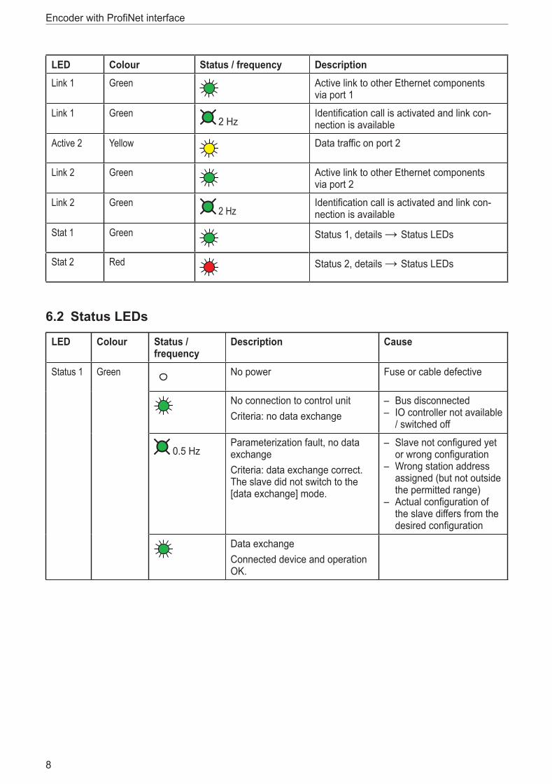
6.2 Status LEDs
LED Colour Status / frequency
Description Cause
Status 1 Green No power Fuse or cable defective
No connection to control unitCriteria: no data exchange
– Bus disconnected – IO controller not available
/ switched off
0�5 HzParameterization fault, no data exchangeCriteria: data exchange correct� The slave did not switch to the [data exchange] mode�
– Slave not configured yet or wrong configuration
– Wrong station address assigned (but not outside the permitted range)
– Actual configuration of the slave differs from the desired configuration
Data exchangeConnected device and operation OK�

UK
Encoder with ProfiNet interface
9
LED Colour Status / frequency
Description Cause
Status 1 (fault)
Red No power Fuse or cable defective
No connection to control unitCriteria: no data exchange
– Bus disconnected – IO controller not available
/ switched off
0�5 HzParameterization fault, no data exchangeCriteria: data exchange correct� The slave did not switch to the [data exchange] mode�
– Slave not configured yet or wrong configuration
– Wrong station address assigned (but not outside the permitted range)
– Actual configuration of the slave differs from the desired configuration
Data exchangeConnected device and operation OK�
7 Installation ► Disconnect power� ► Ensure that the machine stands still� ► The drive must not be started during installation� ► Do not hit the shaft; do not use a file or similar tool on the shaft: Risk of destruction!
This product is a precision measuring device� Therefore it has to be handled with care by trained staff� The following warnings apply to influences outside the limit values indicated in the product data sheet�
Damage to the product can be caused by: ● electrostatic discharge while touching the electronics ● too high forces on the shaft ● humidity and chemical liquids (do not connect any cables oriented upwards) ● extreme temperatures ● too high vibrations and shocks ● short circuit or too high an operating voltage ● impact, shock or any other physical forces

Encoder with ProfiNet interface
10
8 Device configuration8.1 StandardisationThe current generation of ProfiNet encoders is based on the profile V4�0/V4�1 (PNO no� 3�162)� With this standardisation it is possible to substitute all products that fulfil the specification�
PROFIBUSNetwork
PROFINETNetwork
PROFINET IOPNO No. 2.332
PROFIBUS DP-V2IEC 61158 PROFIDRIVE V4
PNO No. 3.172
I&M Functions
PNO No. 3.502
Encoder Profile V4
Class 3 and 4
PNO No. 3.162
Encoder Profile
Class 1 and 2
PNO No. 3.062
PROFIBUS DPEN 50170
8.2 Encoder classes
Application class Description3 Isochronous mode is not supported (RT)
4 Isochronous mode is supported (IRT)
8.3 Encoder functions
Implementation
Function Class 3 Class 4
Code sequence - / • * •
Class 4 functionality • •
G1_XIST1 preset control - / • * •
Scaling function control - / • * •
Alarm channel control • •
Preset value - / • * •
Preset value (64bit) - -
UK
Encoder with ProfiNet interface
11
Implementation
Function Class 3 Class 4
Measuring units per revolution (32bit) - / • * •
Total resolution (32bit) - / • * •
Measuring units per revolution (64bit) - / • * •
Total resolution (64bit) - / • * •
Maximum master sign-of-life failures - / • * •
Velocity measuring unit - / • * •
Encoder profile version • •
Operating hours counter - -
Offset value - / • * •
Offset value at 64 bits - / • * •
Round axis function • •
Velocity filter • •
* If class 4 functionality is activated
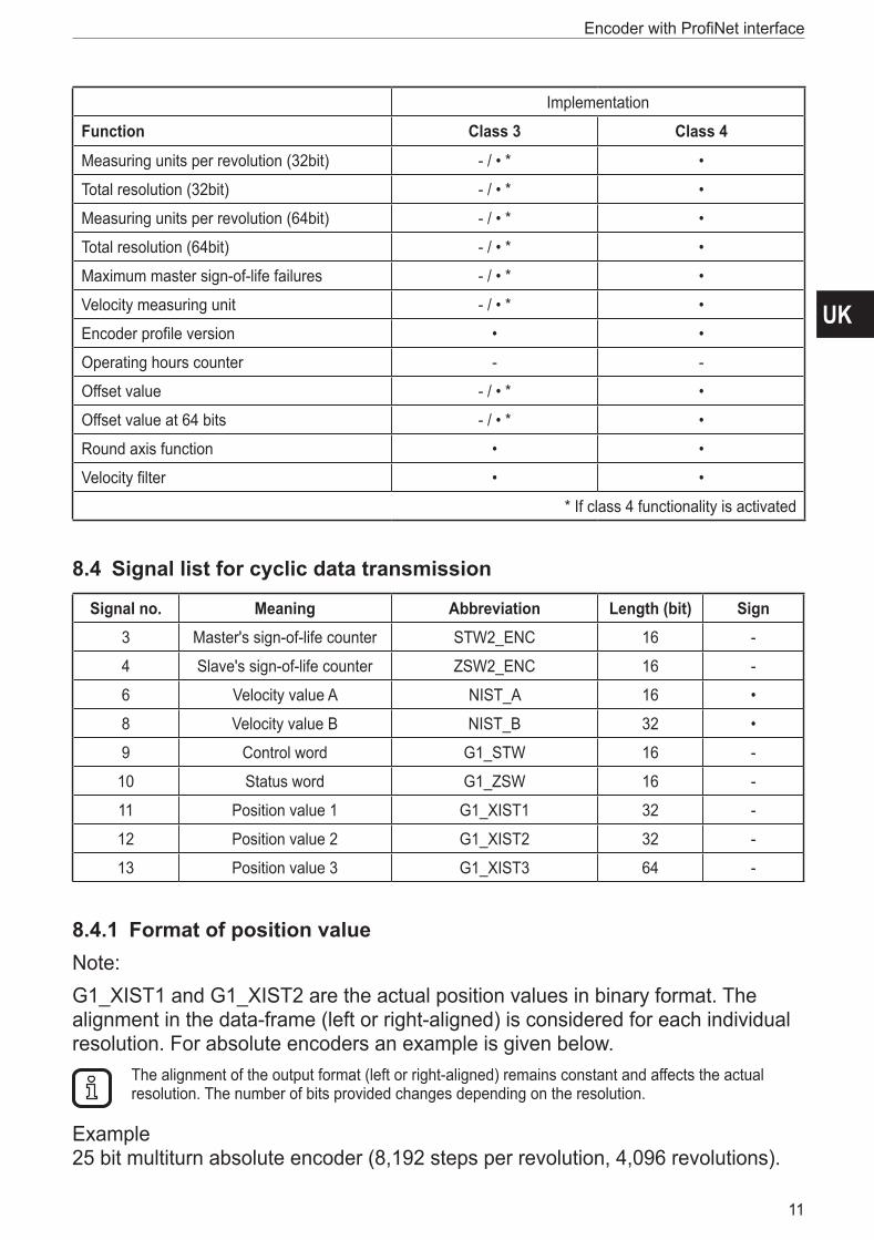
8.4 Signal list for cyclic data transmission
Signal no. Meaning Abbreviation Length (bit) Sign3 Master's sign-of-life counter STW2_ENC 16 -
4 Slave's sign-of-life counter ZSW2_ENC 16 -
6 Velocity value A NIST_A 16 •
8 Velocity value B NIST_B 32 •
9 Control word G1_STW 16 -
10 Status word G1_ZSW 16 -
11 Position value 1 G1_XIST1 32 -
12 Position value 2 G1_XIST2 32 -
13 Position value 3 G1_XIST3 64 -
8.4.1 Format of position valueNote: G1_XIST1 and G1_XIST2 are the actual position values in binary format� The alignment in the data-frame (left or right-aligned) is considered for each individual resolution� For absolute encoders an example is given below�
The alignment of the output format (left or right-aligned) remains constant and affects the actual resolution� The number of bits provided changes depending on the resolution�
Example 25 bit multiturn absolute encoder (8,192 steps per revolution, 4,096 revolutions)�

Encoder with ProfiNet interface
12
All values are presented in binary format� If an error occurs, G1_XIST2 displays the error telegram instead of the right-aligned value�The shifting factors in P979 "sensor format" display the current format� P979, subindex 4 (shift factor for G1_XIST2) = 0� The settings in the encoder parameter data affect the position value in both G1_XIST1 and G1_XIST2�Absolute value in G1_XIST2
31���25 24���13 12���0
M S
Distinguishable revolutions
(multiturn value)
Pulses (singleturn steps per revolution)
Setting: encoder profile 4.0* ● By default, G1_XIST1 is left-aligned� ● P979, subindex 3 (shift factor for G1_XIST1) = 32 – total resolution (next binary
value) ● G1_XIST1 transmits positions values independent of bit 10 in stw2 and bit 13 in
g1_stw1�Absolute value in G1_XIST1 for encoder profile 4�0
31���20 19���7 6���0
M S
Distinguishable revolutions
(multiturn value)
Pulses (singleturn steps per revolution)
Setting: encoder profile 4.1* ● By default, G1_XIST1 is right-aligned� ● A 32-bit counter starts with the absolute position value� After increasing to the
maximum counter value, start again with 0 or decreasing from the max� counter value to 0�
● P979, subindex 3 (shift factor for G1_XIST1) = 0 ● G1_XIST1 transmits positions values independent of bit 10 in stw2 and bit 13 in
g1_stw1�Absolute value in G1_XIST1 for encoder profile 4�1
31���13 19���0
M S
Distinguishable revolutions
(multiturn value)
Pulses (singleturn steps per revolution)
UK
Encoder with ProfiNet interface
13
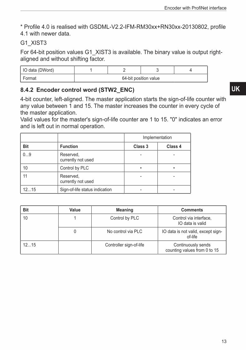
* Profile 4.0 is realised with GSDML-V2.2-IFM-RM30xx+RN30xx-20130802, profile 4�1 with newer data�G1_XIST3 For 64-bit position values G1_XIST3 is available� The binary value is output right-aligned and without shifting factor�
IO data (DWord) 1 2 3 4
Format 64-bit position value
8.4.2 Encoder control word (STW2_ENC)4-bit counter, left-aligned� The master application starts the sign-of-life counter with any value between 1 and 15� The master increases the counter in every cycle of the master application� Valid values for the master's sign-of-life counter are 1 to 15� "0" indicates an error and is left out in normal operation�
Implementation
Bit Function Class 3 Class 40���9 Reserved,
currently not used- -
10 Control by PLC • •
11 Reserved, currently not used
- -
12���15 Sign-of-life status indication - -
Bit Value Meaning Comments10 1 Control by PLC Control via interface,
IO data is valid
0 No control via PLC IO data is not valid, except sign-of-life
12���15 Controller sign-of-life Continuously sends counting values from 0 to 15

Encoder with ProfiNet interface
14
8.4.3 Encoder status word (ZSW2_ENC)4-bit counter, left-aligned� The slave application starts the sign-of-life counter with any value between 1 and 15 after successful synchronisation to the clock pulse� The counter is increased in every DP cycle of the slave application� Valid values for the slave's sign-of-life counter are 1 to 15, "0" indicates an error and is left out in normal operation�
Implementation
Bit Function Class 3 Class 40���8 Reserved,
currently not used- -
9 Control requested Mandatory Mandatory
10���11 Reserved, currently not used
- -
12���15 Encoder sign-of-life counter - Mandatory
Bit Value Meaning Comments9 1 Control requested Control via interface,
IO data is valid
0 No control via PLC IO data is not valid, except sign-of-life
12���15 Encoder Sign-of-life counter
Continuously sends counting values from 0 to 15
8.4.4 Encoder control word (G1_STW)
Bit Value Function Comments0���10 Reserved,
currently not used
11 0/1 "Home position" mode Specifies if the position value shall be set to a previously
programmed absolute value or shifted by this value�
0: set home position / preset (absolute)
1: shift home position / preset (relative = offset)
12 1 Set preset / shift request
Preset (shift) is set when chan-ging this bit to "1" (rising edge)�
Default preset value: (shift): 0Warning:
After setting the preset the offset will be saved in the EEPROM� In these 5-10 ms the encoder will
not send position values�

UK
Encoder with ProfiNet interface
15
Bit Value Function Comments13 1 Request absolute value cyclically Request of additional cyclic trans-
mission of the absolute actual position in G1_XIST2� If no other
data needs to be transferred due to commands or errors the absolute position value will be
transmitted automatically�
14 1 "Parking sensor" activated If the "parking sensor" bit is activated, the encoder transmits
no error messages�
15 1 Acknowledgement of a sensor error
Request to acknowledge / reset a sensor error
8.4.5 Encoder status word (G1_ZSW)
Bit Value Function Comments0���10 Reserved,
currently not used
11 Acknowledgement of a sensor error in process
Is set if the reset of a sensor error takes longer than one bus cycle�
12 1 Set preset value / shift reference point executed
Acknowledgement for "set preset / shift reference point"
13 1 Transmit absolute value cycli-cally
Acknowledgement for "request absolute value cyclically"
14 1 "Parking sensor" activated If the "parking sensor" bit is activated, the encoder transmits
no error messages�
15 1 Acknowledgement of a sensor error
Indicates a sensor error� A device specific error code is
shown in G1_XIST2�
8.5 Standard and vendor telegramsStandard telegram 81
IO data (DWord)
1 2
Setpoint STW2_ENC * G1_STW1 *
IO data (DWord)
1 2 3 4 5 6
Actual value ZSW2_ENC* G1_ZSW1* G1_XIST1* G1_XIST2*
Standard telegram 82
IO data (DWord)
1 2
Setpoint STW2_ENC* G1_STW1 *
Encoder with ProfiNet interface
16
IO data (DWord)
1 2 3 4 5 6 7
Actual value ZSW2_ENC* G1_ZSW1* G1_XIST1* G1_XIST2* NIST_A*
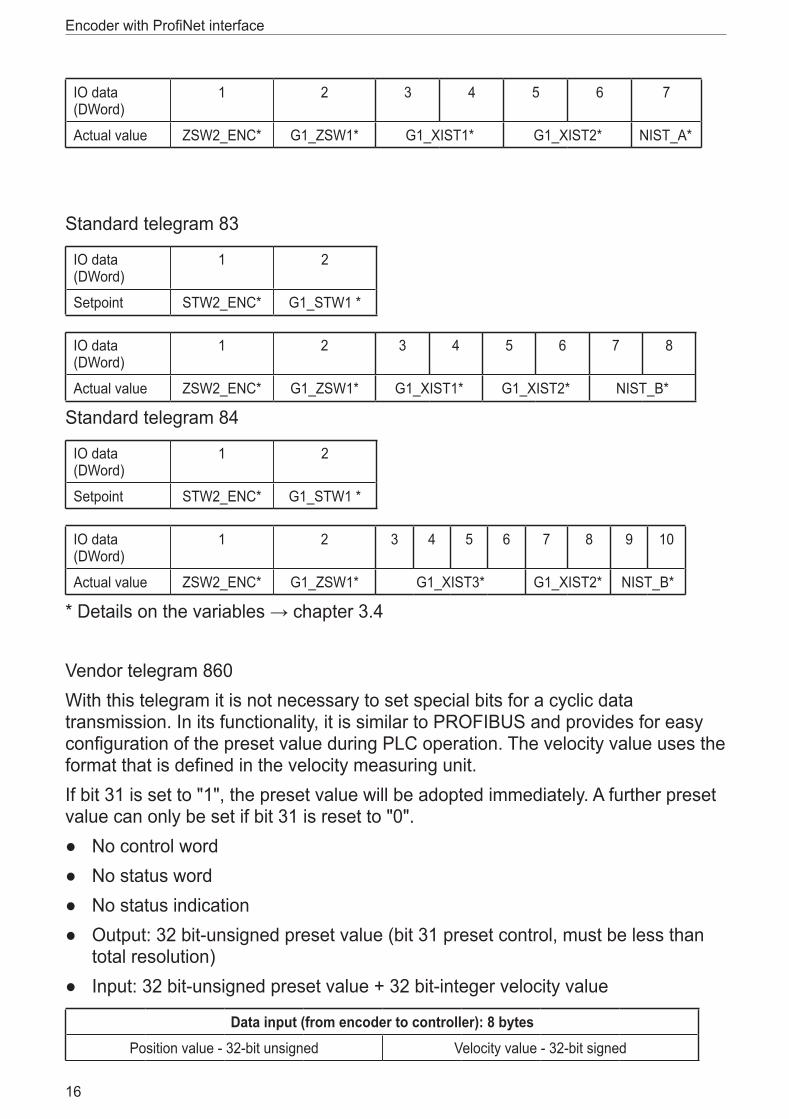
Standard telegram 83
IO data (DWord)
1 2
Setpoint STW2_ENC* G1_STW1 *
IO data (DWord)
1 2 3 4 5 6 7 8
Actual value ZSW2_ENC* G1_ZSW1* G1_XIST1* G1_XIST2* NIST_B*
Standard telegram 84
IO data (DWord)
1 2
Setpoint STW2_ENC* G1_STW1 *
IO data (DWord)
1 2 3 4 5 6 7 8 9 10
Actual value ZSW2_ENC* G1_ZSW1* G1_XIST3* G1_XIST2* NIST_B*
* Details on the variables → chapter 3.4
Vendor telegram 860With this telegram it is not necessary to set special bits for a cyclic data transmission� In its functionality, it is similar to PROFIBUS and provides for easy configuration of the preset value during PLC operation� The velocity value uses the format that is defined in the velocity measuring unit�If bit 31 is set to "1", the preset value will be adopted immediately� A further preset value can only be set if bit 31 is reset to "0"�
● No control word ● No status word ● No status indication ● Output: 32 bit-unsigned preset value (bit 31 preset control, must be less than
total resolution) ● Input: 32 bit-unsigned preset value + 32 bit-integer velocity value
Data input (from encoder to controller): 8 bytesPosition value - 32-bit unsigned Velocity value - 32-bit signed

UK
Encoder with ProfiNet interface
17
Byte 0 Byte 1 Byte 2 Byte 3 Byte 4 Byte 5 Byte 6 Byte 7
MSB LSB MSB LSB
Data output (from controller to encoder): 4 bytesPreset - 32-bit unsigned
Bit 31 Bit 30 ���������������������������������������������������������������������������������bit 0
Preset control Preset value < Total resolution
9 Configuration principleEncoders with ProfiNet interface can be programmed according to the needs of the user�
► The GSDML file of the encoder has to be installed in the PLC software tool�
9.1 Overview of encoder functions
Function Communication channelPosition value Cyclic input (IO device -> IO controller)
Preset Cyclic output (IO controller -> IO device)
Code sequence Acyclic input/output
Scaling function Acyclic input/output
9.2 Encoder functions – Data formatProfiNet IO devices are set up in modules� Each module can be assigned to slot� One sub slot can contain several cyclic input/output channels as well as acyclic record channels (required for parameters)�There are PLC versions from different manufacturers available� Some of them support only one sub slot� Others, e�g� S7 400, support several sub slots� To work with all PLCs there are two directories in the GSDML file: standard (for IRT) and "no PDEV"�ifm encoders offer for the standard profile one slot with one sub slot for all old PLCs that do not support several sub slots�Device parameters are systematically grouped together in a table� The following tables give an overview of the ifm encoder functions�

Encoder with ProfiNet interface
18
EncoderGSDML file
ControllerSPS project tool
1 2
1: Acyclic data transmission (parameters)2: Cyclic data transmission (process data)

UK
Encoder with ProfiNet interface
19
9.3 Parameters for acyclic data transmissionIn the start-up phase the user parameters are sent to the encoder as data record object for mapping of the different encoder functions in the user data section (data record 0xBF00)� In addition to the parameter "data configuration" the encoder supports a number of PROFIdrive parameters and encoder specific parameters via the acyclic data exchange service� With GSDML version GSDML-V2�2-IFM-RM30xx+RN30xx-20130802, it is possible to change the telegram type without changing the MAP parameters�
MAP
Parameter
Access
EncoderFunctions
ParameterManager
ParameterData Base
Standard
Telegram 81.
82, 83 or 84
Sub 1 Sub 2Sub 2Sub 0
Slot 1 Standard Telegrams
Sub 0
Slot 0

Encoder with ProfiNet interface
20
9.3.1 Standard parameters
Function Slot Sub slot Index Offset Length IOCode sequence 1 1 0xBF00 0�0 1 bit -
Class 4 functionality 1 1 0xBF00 0�1 1 bit -
G1_XIST1 preset control 1 1 0xBF00 0�2 1 bit -
Scaling function control 1 1 0xBF00 0�3 1 bit -
Alarm channel control 1 1 0xBF00 0�4 1 bit -
Compatibility mode 1 1 0xBF00 0�5 1 bit -
Measuring units per revolution 1 1 0xBF00 1 8 bytes -
Total resolution 1 1 0xBF00 9 8 bytes -
Maximum master sign-of-life failures
1 1 0xBF00 17 1 byte -
Velocity unit 1 1 0xBF00 18 1 byte -
9.3.2 Device parameters
Function Slot Sub slot Index Offset Length IOPreset value 1 1 0xB02E via parameter no�
65000-
9.3.3 Vendor parameters
Function Slot Sub slot Index Offset Length IOPreset value 1 1 0x1000 0 1 byte -
9.4 Supported parameters
Number Parameter Read only Read/Write
922 Telegram selection • -
925 Number of tolerated sign-of-life failures - •
964 Device identification • -
965 Profile identification number • -
971 Transfer into EEPROM - •
975 DO identification • -
979 Sensor format • -
980 List of defined parameters • -
65000 Preset - •
65001 Operating status • -

UK
Encoder with ProfiNet interface
21
Parameter model
.
.
.
.
.
.
.
.
.
.
.
.
.
.
.
.
.
.
.
.
.
.
.
.
Request Reference Request ReferenceResponse ID Request ID
DO-ID No of Parameters DO-ID No of Parameters
Parameterresponse
Parameterrequest
ParameterResponse
Data Record0xB02E (READ)
Data Record0xB02E (WRITE)
Controller/Supersivor
PROFIdriveBase ModeParameterresponse
PROFIdriveBase ModeParameter
request
writeData Record
0xB02E
readData Record
0xB02E
error: 1)ErrorCode = 0xDEErrorDecode = 0x80ErrorCode 1 = 0xB5ErrorCode 2 = 0
ParameterRequesterror: 3)ErrorCode = 0xDFErrorDecode = 0x80ErrorCode 1 = 0xB5ErrorCode 2 = 0
requestaccepted
error “state conflict”, request
not acceptedreadout ofparameterresponseerror “state conflict”,
no responseavailable
ok
ok
transferresponse toData Record
transferrequest toParameter
Manager
BlockHeader;ParameterRequest
BlockHeader;ParameterResponse
ParameterManager 2)
ParameterData Base
Drive / DO
PROFIdriveBase Mode Parameter
request
PROFIdriveBase Mode Parameter
response
Request Reference Request ReferenceResponse ID Request ID
DO-ID No of Parameters DO-ID No of Parameters

Encoder with ProfiNet interface
22
Example of configuration according encoder profile V4�1
9.5 Encoder function description
Implementation Description chapterFunction Class 3 Class 4
Code sequence - / • * • 9�5�1
Class 4 functionality • • 9�5�2
G1_XIST1 preset control - / • * • 9�5�3
Scaling function control - / • * • 9�5�4
Alarm channel control • • 9�5�5
Compatibility mode • • 9�5�6
Preset value - / • * • 9�5�7
Preset value (64 bits) - - -
Measuring units per revolution (32 bits) - / • * • 9�5�9
Total measuring range (32 bits) - / • * • 9�5�9
Measuring units per revolution (64 bits) - / • * • -
Total measuring range (64 bits) - / • * • -
Maximum master sign-of-life failures - / • * • 9�5�10
Velocity unit - / • * • 9�5�11
Encoder profile version • • 9�5�14
Operating hours counter - - -
Offset value - / • * • 9�5�8
Offset value 64 bits - / • * • -

UK
Encoder with ProfiNet interface
23
Implementation Description chapterFunction Class 3 Class 4
Round axis functionality • • 9�5�13
Velocity filter • • 9�5�12
* If class 4 functionality is activated
9.5.1 Code sequenceThe parameter "code sequence" defines the counting direction of the position value� The value increases when the shaft is rotating clockwise (CW) or counter-clockwise (CCW) (view onto the shaft)�
Code sequence Direction of rotation when viewing the shaft Code sequence922 Clockwise (CW) Increasing
925 Counter-clockwise (CCW) Decreasing
9.5.2 Class 4 functionalityThe parameter "class 4 functionality" defines that scaling, preset and code sequence affect the position value in G1_XIST1, G1_XIST2 and G1_XIST3�
Class 4 control Class 4 function0 (standard) Deactivated (disable)
1 Activated (enable)
9.5.3 Preset control for G1_XIST1The parameter "preset control" defines the preset function� If parameter class 4 is activated and preset control is deactivated, then the preset value will not be affected in G1_XIST1�
Preset control Preset function0 (standard) Preset does not affect G1_XIST1
1 Preset affects G1_XIST1
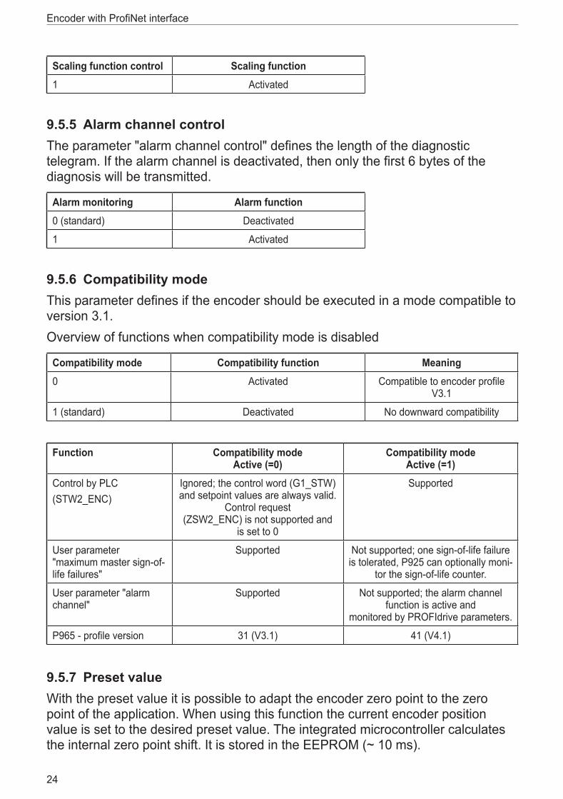
9.5.4 Scaling function controlThe parameter "scaling function control" activates / deactivates the scaling function� If it is not activated, the physical position value is returned by the encoder� Scaling function control is only available when class 4 control is activated�
Scaling function control Scaling function0 (standard) Deactivated
Encoder with ProfiNet interface
24
Scaling function control Scaling function1 Activated
9.5.5 Alarm channel controlThe parameter "alarm channel control" defines the length of the diagnostic telegram� If the alarm channel is deactivated, then only the first 6 bytes of the diagnosis will be transmitted�
Alarm monitoring Alarm function0 (standard) Deactivated
1 Activated
9.5.6 Compatibility modeThis parameter defines if the encoder should be executed in a mode compatible to version 3�1� Overview of functions when compatibility mode is disabled
Compatibility mode Compatibility function Meaning0 Activated Compatible to encoder profile
V3�1
1 (standard) Deactivated No downward compatibility
Function Compatibility mode Active (=0)
Compatibility mode Active (=1)
Control by PLC(STW2_ENC)
Ignored; the control word (G1_STW) and setpoint values are always valid�
Control request (ZSW2_ENC) is not supported and
is set to 0
Supported
User parameter "maximum master sign-of-life failures"
Supported Not supported; one sign-of-life failure is tolerated, P925 can optionally moni-
tor the sign-of-life counter�
User parameter "alarm channel"
Supported Not supported; the alarm channel function is active and
monitored by PROFIdrive parameters�
P965 - profile version 31 (V3�1) 41 (V4�1)
9.5.7 Preset valueWith the preset value it is possible to adapt the encoder zero point to the zero point of the application� When using this function the current encoder position value is set to the desired preset value� The integrated microcontroller calculates the internal zero point shift� It is stored in the EEPROM (~ 10 ms)�

UK
Encoder with ProfiNet interface
25
Set preset only in standstill�
There is no preset activated when the preset value is written to the encoder�The preset function is controlled by the bits in sensor control and status words (G1_STW and G1_ZSW)� The preset value is used when a preset is requested by bit 12 of the sensor control (G1_STW)�
Class 4 functionality must be enabled�
If the preset value is greater than the total resolution, then the error message 0x02 (lower or higher limit value exceeded) appears in the parameter response in base mode�
Parameter Meaning Data typePreset value Preset value is defined via asynchronous
data exchange� Default value = 0
Integer 32
Encoder with ProfiNet interface
26
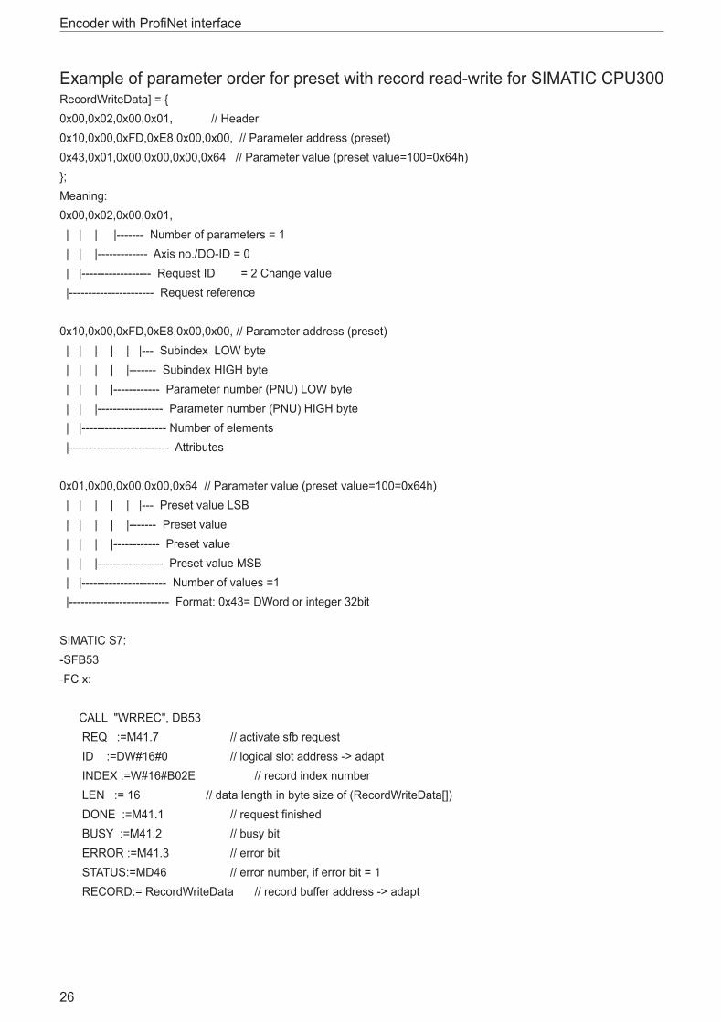
Example of parameter order for preset with record read-write for SIMATIC CPU300RecordWriteData] = {0x00,0x02,0x00,0x01, // Header0x10,0x00,0xFD,0xE8,0x00,0x00, // Parameter address (preset) 0x43,0x01,0x00,0x00,0x00,0x64 // Parameter value (preset value=100=0x64h)};Meaning:0x00,0x02,0x00,0x01, | | | |------- Number of parameters = 1 | | |------------- Axis no�/DO-ID = 0 | |------------------ Request ID = 2 Change value |---------------------- Request reference
0x10,0x00,0xFD,0xE8,0x00,0x00, // Parameter address (preset) | | | | | |--- Subindex LOW byte | | | | |------- Subindex HIGH byte | | | |------------ Parameter number (PNU) LOW byte | | |----------------- Parameter number (PNU) HIGH byte | |---------------------- Number of elements |-------------------------- Attributes
0x01,0x00,0x00,0x00,0x64 // Parameter value (preset value=100=0x64h) | | | | | |--- Preset value LSB | | | | |------- Preset value | | | |------------ Preset value | | |----------------- Preset value MSB | |---------------------- Number of values =1 |-------------------------- Format: 0x43= DWord or integer 32bit
SIMATIC S7:-SFB53-FC x:
CALL "WRREC", DB53 REQ :=M41�7 // activate sfb request ID :=DW#16#0 // logical slot address -> adapt INDEX :=W#16#B02E // record index number LEN := 16 // data length in byte size of (RecordWriteData[]) DONE :=M41�1 // request finished BUSY :=M41�2 // busy bit ERROR :=M41�3 // error bit STATUS:=MD46 // error number, if error bit = 1 RECORD:= RecordWriteData // record buffer address -> adapt

UK
Encoder with ProfiNet interface
27
9.5.8 Offset valueThe offset value is calculated in the preset function and exchanges the position value for the calculated value�
9.5.9 Scaling parametersThe scaling parameters are used to change the resolution� This parameter only refers to the output values if the scaling function is enabled�
Parameter Meaning Data typeMeasuring units per revolution
Singleturn resolution in steps Unsigned 32
Total measuring range in measuring units
Total measuring range Unsigned 32
If the resolution per revolution is reduced, a skip in the position value may occur when crossing the physical zero point� Reason: The position values exceed the real total resolution� Use the formula below to avoid this problem:Total resolution = desired measuring steps / revolution x revolutions
9.5.10 Maximum master sign-of-life failures
With this parameter the number of allowed failures of the master's sign of life is defined�
Parameter Meaning ValueMaximum master sign-of-life failures
Number of permissible failures of the sign-of-life counter
0 … 255Standard =1
9.5.11 Velocity measuring unitsThis parameter defines the coding of velocity measuring unit used to configure the values NIST_A and NIST_B� Only telegrams 82-84 use the velocity outputs�
Velocity unit ValueSteps / s 0
Steps / 100 ms 1
Steps / 10 ms 2
RPM 3
N2/N4 4

Encoder with ProfiNet interface
28
N2/N4: Velocity scaling used for PROFIdrive telegrams The current velocity value in NIST is the share in per cent of the reference value� The reference value can be programmed with parameter P2000�
● N2 (NIST_A), 4000 hex corresponds to a value of 100% of the reference value ● N4 (NIST_B), 4000 0000 hex corresponds to a value of 100% of the reference
value ● The value range is between -200% and +200%
MSB = 1 corresponds to a negative signMSB = 0 corresponds to a positive sign
9.5.12 Velocity filterThe velocity value can be used with three different exponential moving average filter types�
Parameter Meaning Data typeVelocity filter Parameter selection: fine, normal, coarse Integer 32
Ratio between old and current velocity: – Fine: 7:3 – Normal: 96:4 – Coarse: 996:4
9.5.13 Endless shaft (round axis)Normally the "total resolution" / "measuring units per revolution" must be an integer and the total resolution must fit an integer number of times into 8192 for an encoder with 13 bits per revolution� This means that e�g� 100 or 325 revolutions could cause troubles� So the following equation must apply: (4096 x measuring units per revolution) / total resolution = integerBut the ProfiNet encoder solves this problem automatically� The encoder checks whether the parameters need the endless shaft and activates this functionality independently�
The internal software routine only works if the encoder is in operation� If it is necessary to turn the encoder shaft more than 1,024 revolutions without power supply this can lead to problems (the internal routine will not work without power supply)� With this function there will be saved additional values in the internal EEPROM�

UK
Encoder with ProfiNet interface
29
9.5.14 Encoder profile versionThe encoder profile version is implemented in the encoder� This parameter is not affected by the compatibility settings�
Bits Meaning0���7 Profile version, least significant number (value range: 0…99), decimal coding
8���15 Profile version, most significant number (value range: 0…99), decimal coding
16���31 Reserved
Encoder with ProfiNet interface
30
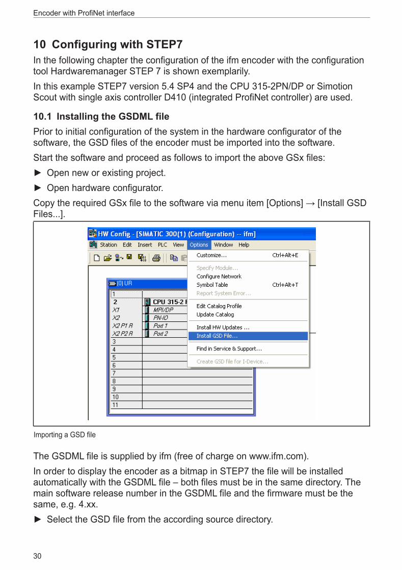
10 Configuring with STEP7In the following chapter the configuration of the ifm encoder with the configuration tool Hardwaremanager STEP 7 is shown exemplarily�In this example STEP7 version 5�4 SP4 and the CPU 315-2PN/DP or Simotion Scout with single axis controller D410 (integrated ProfiNet controller) are used�
10.1 Installing the GSDML filePrior to initial configuration of the system in the hardware configurator of the software, the GSD files of the encoder must be imported into the software� Start the software and proceed as follows to import the above GSx files:
► Open new or existing project� ► Open hardware configurator�
Copy the required GSx file to the software via menu item [Options] → [Install GSD Files���]�
Importing a GSD file
The GSDML file is supplied by ifm (free of charge on www�ifm�com)� In order to display the encoder as a bitmap in STEP7 the file will be installed automatically with the GSDML file – both files must be in the same directory� The main software release number in the GSDML file and the firmware must be the same, e�g� 4�xx�
► Select the GSD file from the according source directory�

UK
Encoder with ProfiNet interface
31
Selecting the GSD file from the directory
After correct import and an update of the hardware catalogue via [Options] → [Update catalog] the modules will be displayed as separate entries in the hardware catalogue�
The exact configuration procedure can be found in the operating manual which is supplied together with the software�
10.2 Adding an encoder to a STEP7 projectTo add an encoder to a project, drag the device [OCD-ENCODER] to an existing ProfiNet Ethernet network (or choose the network and double-click the [OCD-Encoder] icon)�
► Move the telegram to the free slot�Encoder selection
– Standard encoder with PDEV (asynchronous + RT + IRT) – Standard encoder without PDEV (asynchronous + RT)

Encoder with ProfiNet interface
32
10.2.1 Standard encoder without PDEVAsynchronous + RT communication for controllers which do not support IRT functionality�
Standard encoder without ohne PDEV
UK
Encoder with ProfiNet interface
33
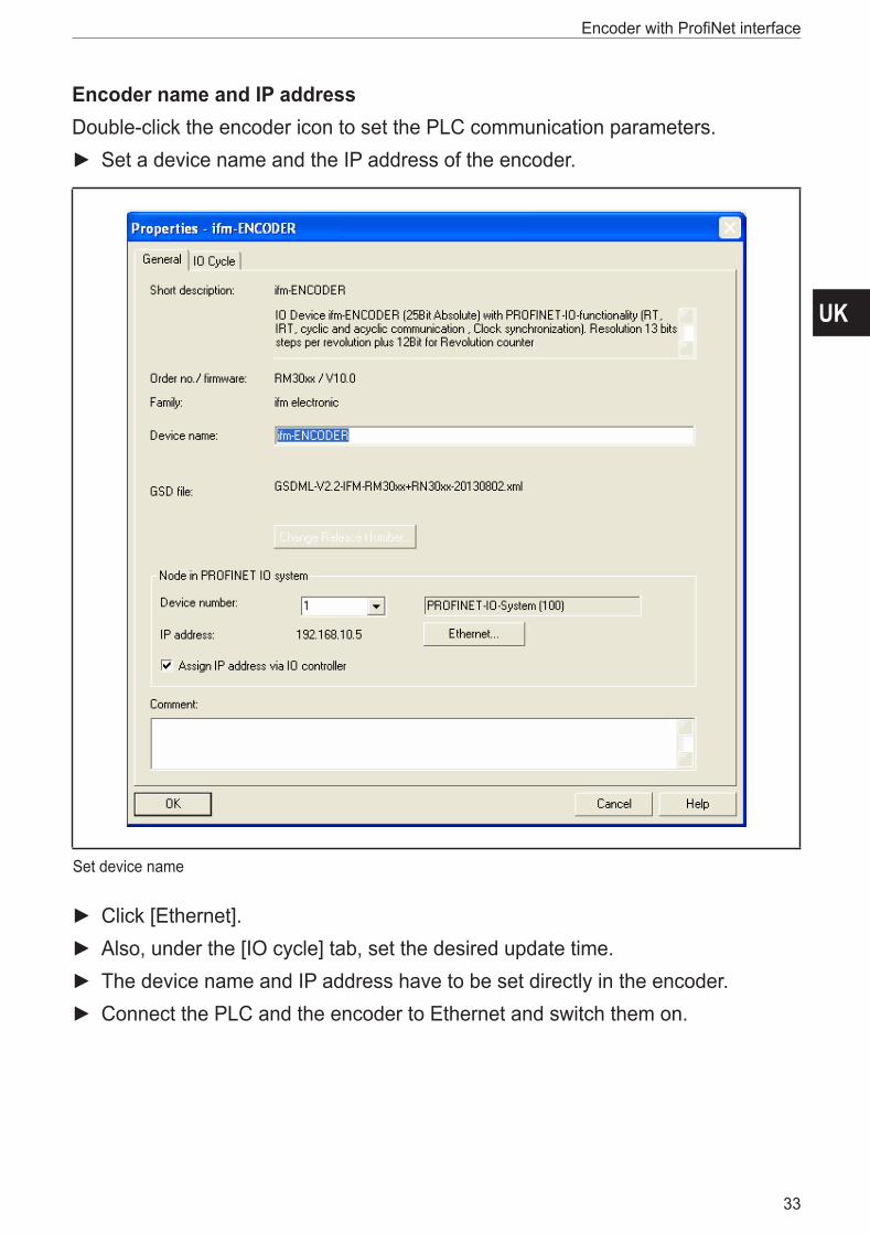
Encoder name and IP addressDouble-click the encoder icon to set the PLC communication parameters�
► Set a device name and the IP address of the encoder�
Set device name
► Click [Ethernet]� ► Also, under the [IO cycle] tab, set the desired update time� ► The device name and IP address have to be set directly in the encoder� ► Connect the PLC and the encoder to Ethernet and switch them on�
Encoder with ProfiNet interface
34
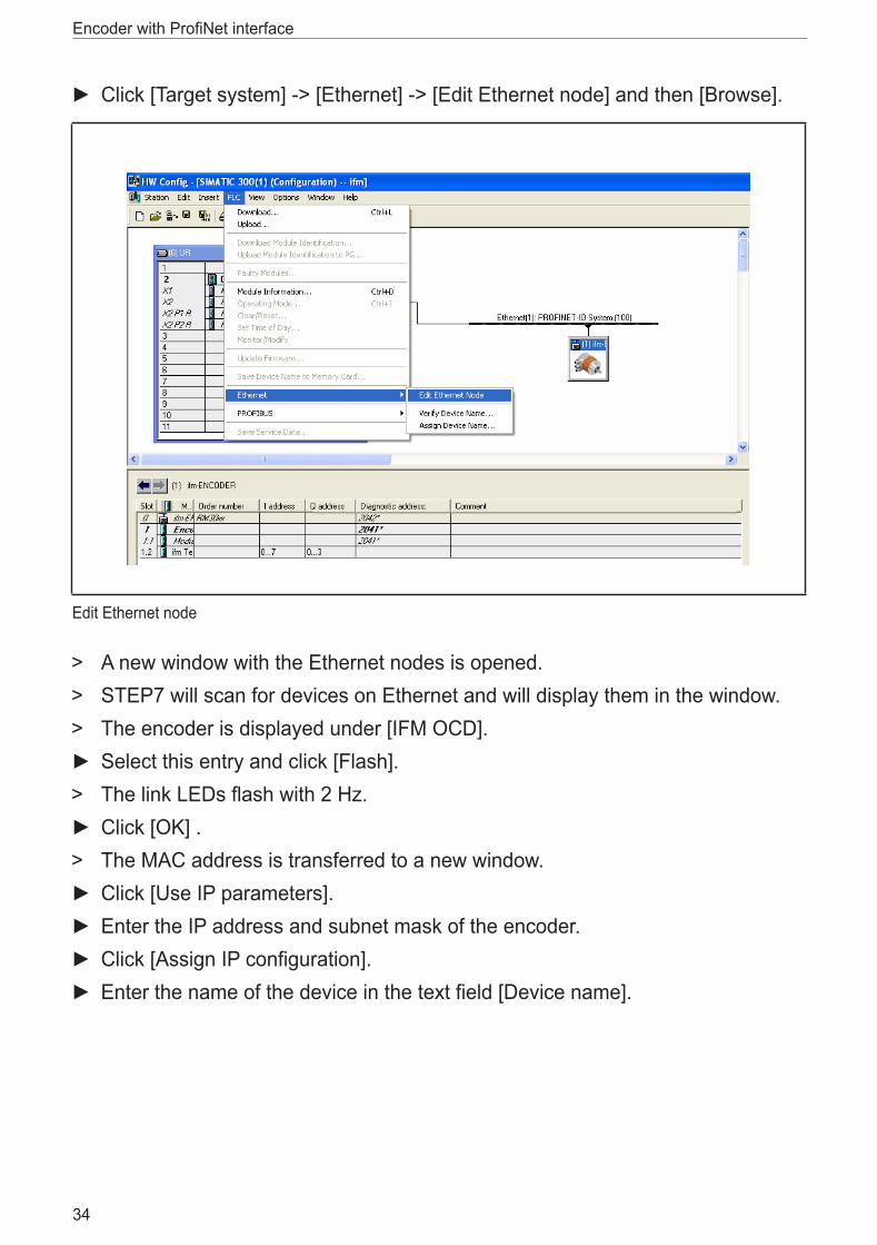
► Click [Target system] -> [Ethernet] -> [Edit Ethernet node] and then [Browse]�
Edit Ethernet node
> A new window with the Ethernet nodes is opened� > STEP7 will scan for devices on Ethernet and will display them in the window� > The encoder is displayed under [IFM OCD]� ► Select this entry and click [Flash]�
> The link LEDs flash with 2 Hz� ► Click [OK] �
> The MAC address is transferred to a new window� ► Click [Use IP parameters]� ► Enter the IP address and subnet mask of the encoder� ► Click [Assign IP configuration]� ► Enter the name of the device in the text field [Device name]�

UK
Encoder with ProfiNet interface
35
► Click [Assign name]�If more than one encoder is used in the same ProfiNet network, each encoder must be assigned a different name�
Browse network
Encoder with ProfiNet interface
36
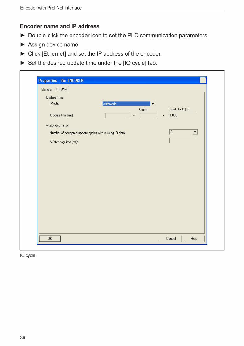
Encoder name and IP address ► Double-click the encoder icon to set the PLC communication parameters� ► Assign device name� ► Click [Ethernet] and set the IP address of the encoder� ► Set the desired update time under the [IO cycle] tab�
IO cycle

UK
Encoder with ProfiNet interface
37
10.3 Module Access Point parameter setup: ► Double-click on the menu item [Module Access Point]�
Module Access Point
> The window with the list of parameters is opened�

Encoder with ProfiNet interface
38
These parameters will be transmitted to the encoder on each start of the PLC�
Parameter settings

UK
Encoder with ProfiNet interface
39


![Device manual ProfiNet encoder - ifm · Encoder with ProfiNet interface 4 1 Preliminary note 1.1 Symbols used Instructions > Reaction, result […] Designation of keys, buttons or](https://static.fdocuments.in/doc/165x107/5b6c5a087f8b9a962a8b6fb6/device-manual-profinet-encoder-ifm-encoder-with-profinet-interface-4-1-preliminary.jpg)