Absolute multiturn encoder TRT/S3 with PROFIsafe on ... · Model TRT/S3 is an electromagnetic...
49
TWK-ELEKTRONIK GmbH D-40041 Düsseldorf Tel. +49 211 96117-0 [email protected] Heinrichstrasse 85 Postbox 10 50 63 Fax +49 211 637705 www.twk.de Document no.: TRT 12846 KE Datum: 07.08.2018 Absolute multiturn encoder TRT/S3 with PROFIsafe on PROFINET interface Relevant data sheet TRT 12845 User manual Translation of the original instructions
-
Upload
nguyenkiet -
Category
Documents
-
view
221 -
download
0
Transcript of Absolute multiturn encoder TRT/S3 with PROFIsafe on ... · Model TRT/S3 is an electromagnetic...

TWK-ELEKTRONIK GmbH D-40041 Düsseldorf Tel. +49 211 96117-0 [email protected] 85 Postbox 10 50 63 Fax +49 211 637705 www.twk.de
Document no.: TRT 12846 KEDatum: 07.08.2018
Absolute multiturn encoder TRT/S3 with PROFIsafe on PROFINET interfaceRelevant data sheet TRT 12845
User manualTranslation of the original instructions

Datum: 07.08.2018 Seite 2 von 49 Document no. TRT 12846 KE
COPYRIGHT: The Operating Instructions TRT 12846is owned by TWK-ELEKTRONIK GMBH and is
protected by copyright laws and international treaty provisions.
© 2018 by TWK-ELEKTRONIK GMBHPOB 10 50 63 ■ 40041 Düsseldorf ■ GermanyTel. +49/211/96 11 70 ■ Fax +49/211/63 77 05
[email protected] ■ www.twk.de

Datum: 07.08.2018 Seite 3 von 49 Document no. TRT 12846 KE
Inhaltsverzeichnis
1. Safety instructions ............................................................................................................. 61.1 Scope ...........................................................................................................................................6
1.2 Documentation .............................................................................................................................6
1.3 Proper use ...................................................................................................................................6
1.4 Commissioning ............................................................................................................................6
2. General information ........................................................................................................... 7
3. Installation........................................................................................................................... 83.1 General information ....................................................................................................................8
3.2 Electrical connection ....................................................................................................................8
3.3 Status LEDs .................................................................................................................................9
3.4 Project planning ...........................................................................................................................9
4. Project planning with Simatic Step7............................................................................... 10
4.1 Step7, Distributed Satety - Simatic Manager ............................................................... 104.1.1 Prerequisites ...........................................................................................................................10
4.1.2 Installation of the GSD file ......................................................................................................10
4.1.3 Installing the absolute encoder ............................................................................................... 11
4.1.4 Install module ..........................................................................................................................12
4.1.5 Setting the network data (properties TRT/S3) ........................................................................14
4.1.6 Setting the absolute encoder (properties of the module) ........................................................154.1.6.1 Setting the I/O address .....................................................................................................154.1.6.2 Parameterising the absolute encoder ...............................................................................154.1.6.3 Setting the F parameters ..................................................................................................16
4.1.7 Setting real time mode and the updating time ........................................................................17
4.1.8 Planning of "Device exchange without programming device" and "Automatic commissioning" 17
4.1.9 Assignment of the device name ..............................................................................................18
4.1.10 Resetting to the default settings ...........................................................................................19
4.2 Step7, Safety Advance - TIA-Portal ............................................................................... 204.2.1 Prerequisites ...........................................................................................................................20
4.2.2 Installation of the GSD file ......................................................................................................20
4.2.3 Installing the absolute encoder ...............................................................................................21
4.2.4 Install module ..........................................................................................................................22
4.2.5 Setting the network data .........................................................................................................23
4.2.5.1 Setting the PROFINET / PROFIsafe Adresse ......................................................................23
4.2.5.2 IP-Adresse ...........................................................................................................................24
Table of contents

Datum: 07.08.2018 Seite 4 von 49 Document no. TRT 12846 KE
4.2.5.3 Prioritized startup, media redundancy, update time and synchronisation ............................24
4.2.6 Setting the absolute encoder (properties of the module) ........................................................244.2.6.1 Setting the I/O address .....................................................................................................244.2.6.2 Parameterising the absolute encoder ...............................................................................254.2.6.3 Setting the F parameters ..................................................................................................25
4.2.7 Planning of "Device exchange without programming device" and "Automatic commissioning" 26
4.2.8 Assignment of the device name ..............................................................................................27
4.2.9 Resetting to the factory settings .............................................................................................28
4.3 Application program ...................................................................................................................294.3.1 Remarks ...............................................................................................................................294.3.2 F-Peripherie-DB ...................................................................................................................294.3.3 Accessing the encoder in the F program .............................................................................294.3.4 Example program .................................................................................................................30
5. I/O data .............................................................................................................................. 395.1 Overview ....................................................................................................................................39
5.1.1 Output code R and W .............................................................................................................39
5.1.2 Output code D .........................................................................................................................39
5.3 Position data ..............................................................................................................................395.3.1 Data format coding R ...........................................................................................................405.3.2. Data format coding W .........................................................................................................405.3.3 Data format coding D ...........................................................................................................40
5.4 Velocity ......................................................................................................................................40
5.5 F input data ................................................................................................................................41
5.6 Control word ..............................................................................................................................41
5.7 Preset value (reference value) ...................................................................................................415.7.1 Data format coding R ...........................................................................................................425.7.2. Data format coding W .........................................................................................................425.7.3 Data format coding D ...........................................................................................................42
5.8 F output data ..............................................................................................................................42
6. Parameterisation .............................................................................................................. 436.1 Encoder parameter ....................................................................................................................43
6.1.1 Overview ..............................................................................................................................436.1.2 Description of the absolute encoder parameters .................................................................43
6.2 F parameter ...............................................................................................................................446.2.1 Overview ..............................................................................................................................446.2.2 Description of the F parameters ...........................................................................................44
7. Diagnostic ......................................................................................................................... 46
Table of contents
Datum: 07.08.2018 Seite 5 von 49 Document no. TRT 12846 KE
7.1 Overview ....................................................................................................................................46
7.2 PROFINET alarms .....................................................................................................................46
7.3 Diagnostic data records .............................................................................................................477.3.1 Diagnostic data according to Encoder Class 2 Profile .........................................................47
8. Scope of delivery .............................................................................................................. 49
9. Literature ........................................................................................................................... 49
Table of contents

Datum: 07.08.2018 Seite 6 von 49 Document no. TRT 12846 KE
Safety instructions
1. Safety instructions
1.1 Scope
This user manual is valid exclusively for the following absolute encoders with PROFINET interface:
- TRTxx-xxxxxxxR4096S3xTxx
1.2 Documentation
The following documents must be observed:
- The owner's system-specific operating instructions
- This user manual
- Data sheet number TRT 12845
- The connection assignment enclosed with the device
- Assembly instructions TZY10206 enclosed with the device
1.3 Proper use
The TWK-ELEKTRONIK GmbH absolute encoders and linear transducers are used to register angular or linear positions and make their measured value available in the form of an electrical output signal. As part of a system, they have to be connected to the downstream electronics and must only be used for this purpose.
1.4 Commissioning
• The relevant device may only be set up and operated in combination with this and the documentation speci fied under point 1.2.
• Protect the device against mechanical damage during installation and operation.
• Device commissioning and operation may only be undertaken by a specialist electrician.
• Do not operate the device outside of the limit values specified in the data sheet.
• Check all electrical connections before commissioning the system.

Datum: 07.08.2018 Seite 7 von 49 Document no. TRT 12846 KE
2. General informationModel TRT/S3 is an electromagnetic rotary encoder with a PROFINET interface and PROFIsafe protocol. Thanks to additional internal monitoring measures, it is suitable for use in safety-technical applications up to SIL2 or PLd.
In addition to a safe position signal, the TRT/S3 also supplies a safe speed signal. It offers the same parameteri-sation and diagnostic options as the standard PROFINET and PROFIBUS rotary encoders.
The PROFINET interface according to IEC 61158 / 61784 or PNO specifications, order Nos. 2.712 and 2.722 version 2.2, and the PROFIsafe protocol according to "PROFIsafe – Profile for Safety Technology on PROFIBUS DP and PROFINET IO", order Nos. 3.092 and 3.192 version 2.4, are integrated. PROFIsafe V2 mode is supported.
The specifications can be obtained from the profibus user organisation (www.profibus.com).
General information

Datum: 07.08.2018 Seite 8 von 49 Document no. TRT 12846 KE
Installation
3. Installation
3.1 General information
• During installation, observe the profinet assembly guideline PNO order No.: 8.071
• Use only certified profinet cables, connectors and switches (see "PROFINET Cabling and Interconnection Technology" PNO order No.: 2.252 and "Installation Guideline PROFINET Part 2: Network Components" PNO order No.: 2.252 p2)
• Hubs are not permissible.
• The cable length between two subscribers may be max. 100 m.
• The TWK TRT absolute encoder possesses an integrated switch. This not only enables tree and star topo- logies but also the linear topology.
• Media redundancy protocol support enables the establishment of a redundant ring.
• The setting of addresses, the baud rate or terminating resistors on the device is not necessary.
3.2 Electrical connection
The " ...MT01" type absolute encoders have separate connectors for the supply and the PROFINET system. Port 1 or port 2 are optionally available for the PROFINET connection. Due to the integrated switch, it is irrelevant which port is used.
Connection Designation Connector typePROFINET Port 1 M12x4 D-coded socketPROFINET Port 2 M12x4 D-coded socketVoltage supply 24 VDC M12x4 A-coded pins
Refer to data sheet No. 12886 for connector assignment and ordering information.
View of the rear side of the encoder
24 V voltage supply
Profinet Profinet
UB L/A1 L/A2 NS
Port 2Port 124 VDC Fig.: 1
Datum: 07.08.2018 Seite 9 von 49 Document no. TRT 12846 KE
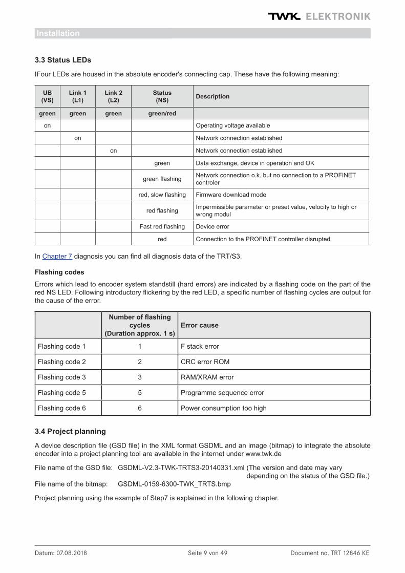
3.3 Status LEDs
IFour LEDs are housed in the absolute encoder's connecting cap. These have the following meaning:
UB (VS)
Link 1 (L1)
Link 2 (L2)
Status(NS) Description
green green green green/red
on Operating voltage available
on Network connection established
on Network connection established
green Data exchange, device in operation and OK
green flashing Network connection o.k. but no connection to a PROFINET controler
red, slow flashing Firmware download mode
red flashing Impermissible parameter or preset value, velocity to high or wrong modul
Fast red flashing Device error
red Connection to the PROFINET controller disrupted
In Chapter 7 diagnosis you can find all diagnosis data of the TRT/S3.
Flashing codesErrors which lead to encoder system standstill (hard errors) are indicated by a flashing code on the part of the red NS LED. Following introductory flickering by the red LED, a specific number of flashing cycles are output for the cause of the error.
Number of flashing
cycles(Duration approx. 1 s)
Error cause
Flashing code 1 1 F stack error
Flashing code 2 2 CRC error ROM
Flashing code 3 3 RAM/XRAM error
Flashing code 5 5 Programme sequence error
Flashing code 6 6 Power consumption too high
3.4 Project planning
A device description file (GSD file) in the XML format GSDML and an image (bitmap) to integrate the absolute encoder into a project planning tool are available in the internet under www.twk.de
File name of the GSD file: GSDML-V2.3-TWK-TRTS3-20140331.xml (The version and date may vary depending on the status of the GSD file.)File name of the bitmap: GSDML-0159-6300-TWK_TRTS.bmp
Project planning using the example of Step7 is explained in the following chapter.
Installation

Datum: 07.08.2018 Seite 10 von 49 Document no. TRT 12846 KE
Project planning with Simatic Step7, Distributed Safety - Simatic Manager
4. Project planning with Simatic Step7
4.1 Step7, Distributed Satety - Simatic ManagerThis chapter explains the procedure for integrating the TWK TRT/S3 absolute encoder into the PROFINET net-work of a Siemens S7 control system with Step7 version 5.5. and Distributed Safety version 5.4
4.1.1 Prerequisites
You have created a hardware configuration in accordance with your control system structure and a PROFINET sub-network.
This is shown here using the example of a CPU314C:
Fig.: 2
4.1.2 Installation of the GSD file
• Under Extras in the hardware configuration, select Install GSD files.• Set "from the directory", "browse" to your GSD file and click on "Install" (see Figure 3).• The absolute encoder symbol is also installed automatically, provided that it is in the same directory
Note: The GSD file and the encoder symbol are available for download under www.twk.de.
Fig.: 3
Datum: 07.08.2018 Seite 11 von 49 Document no. TRT 12846 KE
Fig.: 6
Fig.: 5
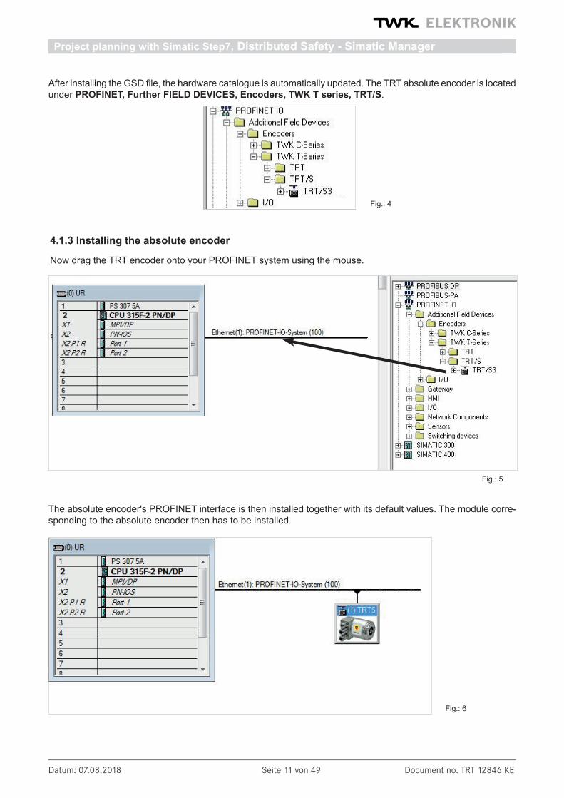
After installing the GSD file, the hardware catalogue is automatically updated. The TRT absolute encoder is located under PROFINET, Further FIELD DEVICES, Encoders, TWK T series, TRT/S.
4.1.3 Installing the absolute encoder
Now drag the TRT encoder onto your PROFINET system using the mouse.
The absolute encoder's PROFINET interface is then installed together with its default values. The module corre-sponding to the absolute encoder then has to be installed.
Fig.: 4
Project planning with Simatic Step7, Distributed Safety - Simatic Manager
Datum: 07.08.2018 Seite 12 von 49 Document no. TRT 12846 KE
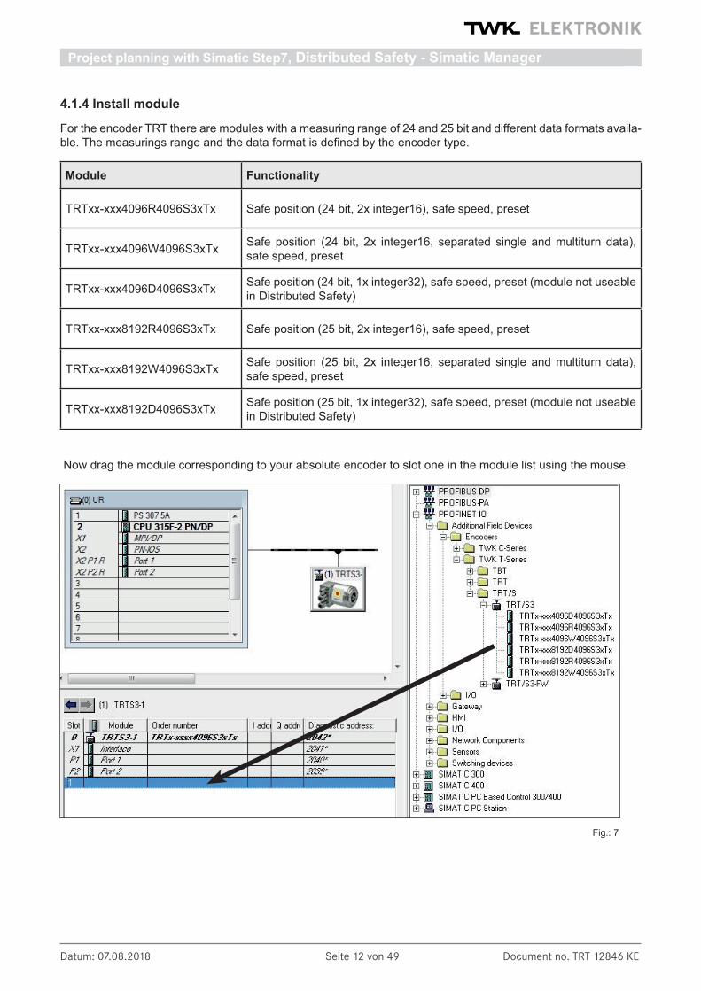
4.1.4 Install module
For the encoder TRT there are modules with a measuring range of 24 and 25 bit and different data formats availa-ble. The measurings range and the data format is defined by the encoder type.
Module Functionality
TRTxx-xxx4096R4096S3xTx Safe position (24 bit, 2x integer16), safe speed, preset
TRTxx-xxx4096W4096S3xTx Safe position (24 bit, 2x integer16, separated single and multiturn data), safe speed, preset
TRTxx-xxx4096D4096S3xTx Safe position (24 bit, 1x integer32), safe speed, preset (module not useable in Distributed Safety)
TRTxx-xxx8192R4096S3xTx Safe position (25 bit, 2x integer16), safe speed, preset
TRTxx-xxx8192W4096S3xTx Safe position (25 bit, 2x integer16, separated single and multiturn data), safe speed, preset
TRTxx-xxx8192D4096S3xTx Safe position (25 bit, 1x integer32), safe speed, preset (module not useable in Distributed Safety)
Now drag the module corresponding to your absolute encoder to slot one in the module list using the mouse.
Fig.: 7
Project planning with Simatic Step7, Distributed Safety - Simatic Manager
Datum: 07.08.2018 Seite 13 von 49 Document no. TRT 12846 KE
Double-click to set the network data
(see Chapter 4.1.5)
Double-click to set the I/O addresses and to
parameterise (see Chapter 4.1.6)
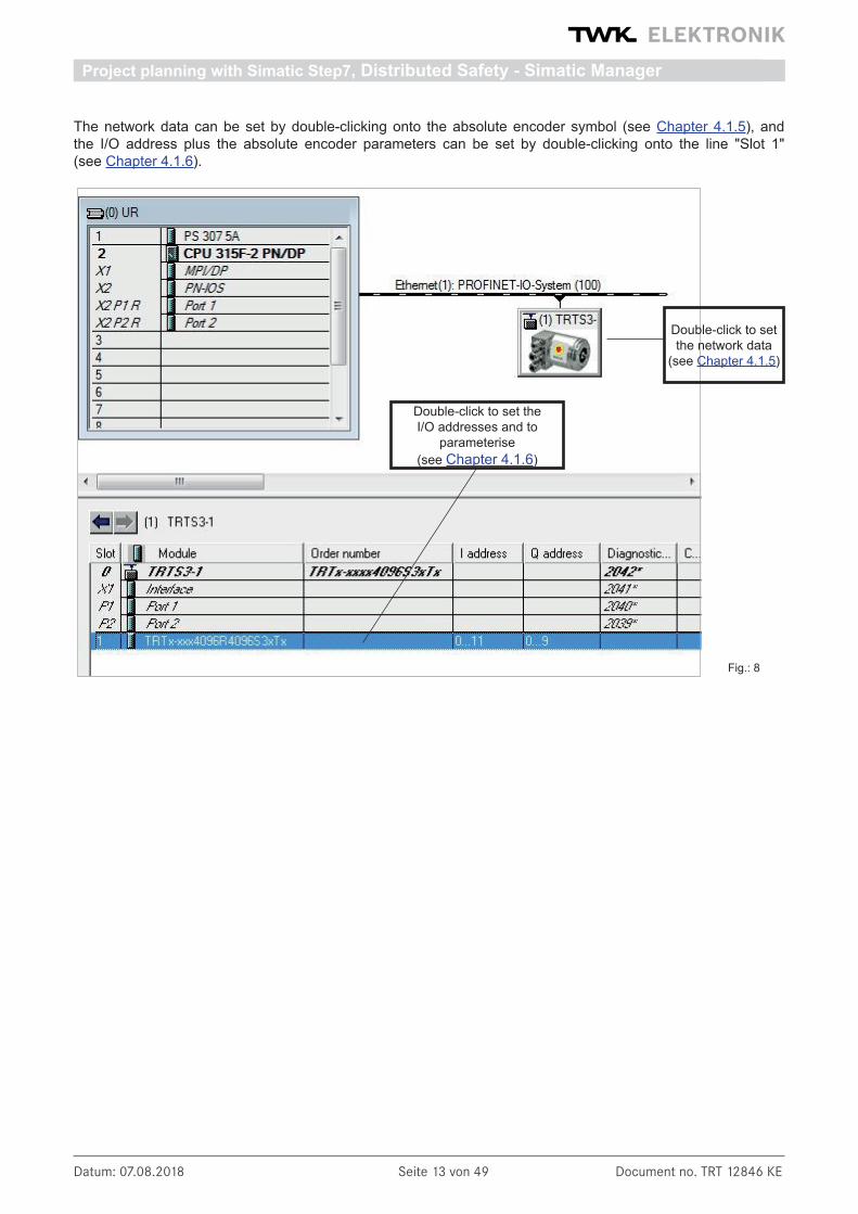
The network data can be set by double-clicking onto the absolute encoder symbol (see Chapter 4.1.5), and the I/O address plus the absolute encoder parameters can be set by double-clicking onto the line "Slot 1" (see Chapter 4.1.6).
Fig.: 8
Project planning with Simatic Step7, Distributed Safety - Simatic Manager
Datum: 07.08.2018 Seite 14 von 49 Document no. TRT 12846 KE
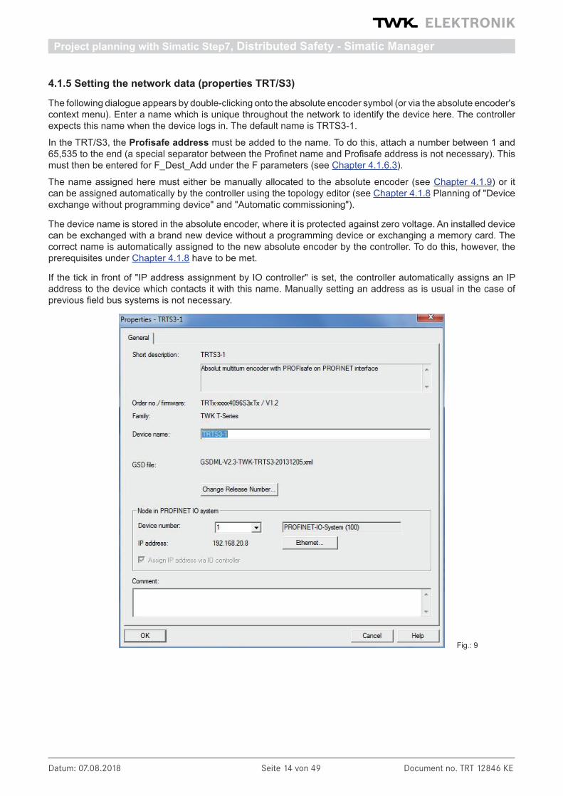
4.1.5 Setting the network data (properties TRT/S3)
The following dialogue appears by double-clicking onto the absolute encoder symbol (or via the absolute encoder's context menu). Enter a name which is unique throughout the network to identify the device here. The controller expects this name when the device logs in. The default name is TRTS3-1.
In the TRT/S3, the Profisafe address must be added to the name. To do this, attach a number between 1 and 65,535 to the end (a special separator between the Profinet name and Profisafe address is not necessary). This must then be entered for F_Dest_Add under the F parameters (see Chapter 4.1.6.3).
The name assigned here must either be manually allocated to the absolute encoder (see Chapter 4.1.9) or it can be assigned automatically by the controller using the topology editor (see Chapter 4.1.8 Planning of "Device exchange without programming device" and "Automatic commissioning").
The device name is stored in the absolute encoder, where it is protected against zero voltage. An installed device can be exchanged with a brand new device without a programming device or exchanging a memory card. The correct name is automatically assigned to the new absolute encoder by the controller. To do this, however, the prerequisites under Chapter 4.1.8 have to be met.
If the tick in front of "IP address assignment by IO controller" is set, the controller automatically assigns an IP address to the device which contacts it with this name. Manually setting an address as is usual in the case of previous field bus systems is not necessary.
Fig.: 9
Project planning with Simatic Step7, Distributed Safety - Simatic Manager
Datum: 07.08.2018 Seite 15 von 49 Document no. TRT 12846 KE
4.1.6 Setting the absolute encoder (properties of the module)
4.1.6.1 Setting the I/O address
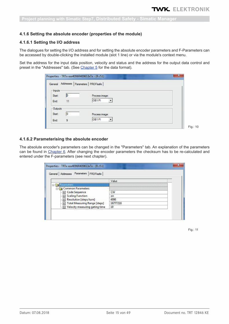
The dialogues for setting the I/O address and for setting the absolute encoder parameters and F-Parameters can be accessed by double-clicking the installed module (slot 1 line) or via the module's context menu.
Set the address for the input data position, velocity and status and the address for the output data control and preset in the "Addresses" tab. (See Chapter 5 for the data format).
4.1.6.2 Parameterising the absolute encoder
The absolute encoder's parameters can be changed in the "Parameters" tab. An explanation of the parameters can be found in Chapter 6. After changing the encoder parameters the checksum has to be re-calculated and entered under the F-parameters (see next chapter).
Fig.: 10
Fig.: 11
Project planning with Simatic Step7, Distributed Safety - Simatic Manager

Datum: 07.08.2018 Seite 16 von 49 Document no. TRT 12846 KE
4.1.6.3 Setting the F parameters
The F parameters must be set in the "PROFIsafe" tab. Here, the Profisafe address attached to the Profinet name must be set under "F_Dest_Add" and a watchdog time corresponding to your system must be specified under "F_WD_Time". "F_Source_Add" is assigned automatically by the S7
Once you have changed the rotary encoder parameters, the checksum must be recalculated using these so-called i parameters and must be entered under "F_iPar_CRC". TWK provides you with the PsCRC pro-gramme for calculating the F_iPar_CRC (see Fig. 12).
An explanation of all F parameters can be found in Chapter 6.2.
The PsCRC programme for calculating the F_ iPar_CRC is available for downloading in the In-ternet under www.twk.de, documentation area, model TRT/S3.
Fig.: 12
Fig.: 13
Project planning with Simatic Step7, Distributed Safety - Simatic Manager

Datum: 07.08.2018 Seite 17 von 49 Document no. TRT 12846 KE
4.1.7 Setting real time mode and the updating time
The following dialogues are accessed via the PROFINET system's context menu:
Setting of the IRT mode and transmission cycle
Setting of the transmission cycle in RT mode and the updating time
Fig.: 14
Set the transmission cycle and the desired updating time in the corresponding dialogue. Alternatively, the upda-ting time can also be set via the interface's object properties. The default value is 2 ms for the updating time and 1 ms for the transmission cycle. The minimum updating time for the TRT/3 is 250 µs.
4.1.8 Planning of "Device exchange without programming device" and "Automatic commissio-ning"
If system restarting without the assignment of a new device name or the IP address is to be possible following the exchange of an installed absolute encoder with a mint condition device, this must be taken into consideration during project planning. This also applies to "Automatic commissioning", in which the manual and, in the case of larger projects, time-consuming assignment of the device name (as described in Chapter 4.1.9) is avoided during commissioning.
The following prerequisites have to be met:
• The controller and the devices must support the function "Device exchange without interchangeable medium or programming device" (for the latter, at least the device itself and its neighbouring devices). The TRT/S3 sup ports this function.
• The function "Device exchange without interchangeable medium" must be activated in the controller. This is the default setting.
• The devices must be in delivery condition, i.e. they must not yet possess any device name.
Now call the topology editor using the PROFINET system's context menu (see Fig. 12) and define all PROFINET connections between the subscribers.
If the project is now loaded into the control system and the actual structure corresponds to the planned topology, all subscribers receive their planned names from the controller and device exchange succeeds without the reas-signment of the device name.
Project planning with Simatic Step7, Distributed Safety - Simatic Manager

Datum: 07.08.2018 Seite 18 von 49 Document no. TRT 12846 KE
Fig.: 15
In the subsequent dialogue, enter the device name, that who have assigned for this encoder in the project planning (see Chapter 4.1.5) and click onto the "Assign name" button. The device name is then stored in the absolute encoder, where it is protected against zero voltage.
The absolute encoder now logs onto the controller with its device name and is then provided with a valid IP address by the controller. This is also stored in the absolute encoder, where it is protected against zero voltage.
Fig.: 16
4.1.9 Assignment of the device name
If a PROFINET topology has not been defined as described in Chapter 4.1.8 or if the prerequisites for automatic commissioning are not met, the absolute encoder name must be assigned manually.
With the absolute encoder connected and the programming device connected to the control system, select "Target sys-tem -> Edit Ethernet subscribers" in the Simatic Manager to do this. Press the "Browse" button in the subsequent dialo-gue. All accessible PROFINET subscri-bers should now be shown as portrayed in the example in Figure 15.
It can be seen that the absolute enco-der device type "TWK T series" does not possess either a valid IP address or a name. Now mark the absolute encoder and exit the dialogue with OK.
TRTS3-1
Project planning with Simatic Step7, Distributed Safety - Simatic Manager

Datum: 07.08.2018 Seite 19 von 49 Document no. TRT 12846 KE
4.1.10 Resetting to the default settings
The absolute encoder can be reset to its delivery condition using the "Reset" button in the "Edit Ethernet subscri-bers" dialogue (Figure 16).
The following are reset Delivery condition
Parameters See Chapter 6.1 for default values
Offset 0 (i.e. the preset setting is undone)
Device name Empty
IP-parameters All 0
I&M0-revision counter 0
After resetting, the connection to the profinet controller is closed and the NS LED lights up red. After switching the voltage off/on, the connection can be re-established by assigning the device name.
If the connections have been defined using the topology editor, the TRT/S3 restarts automatically with the name assigned during project planning.
Project planning with Simatic Step7, Distributed Safety - Simatic Manager

Datum: 07.08.2018 Seite 20 von 49 Document no. TRT 12846 KE
Project planning with Simatic Step7, Advanced Safety - TIA Portal
4.2 Step7, Safety Advance - TIA-PortalThis chapter explains the procedure for integrating the TWK TRT/S3 absolute encoder into the PROFINET net-work of a Siemens S7 control system with Step 7 Professional V13 with Safety Advanced.
4.2.1 Prerequisites
You have created a hardware configuration in accordance with your control system structure and a PROFINET sub-network.
This is shown here using the example of a CPU314C:
4.2.2 Installation of the GSD file
• In the main menu choose Options, Install general station description file (GSD).• Set the source path to your GSD file, check the GSD file and click on "Install" (see Figure 3).• The absolute encoder symbol is also installed automatically, provided that it is in the same directory
Note: The GSD file and the encoder symbol (bitmap) are available for download under www.twk.de.
Fig.: 17
Fig.: 18

Datum: 07.08.2018 Seite 21 von 49 Document no. TRT 12846 KE
Project planning with Simatic Step7, Advanced Safety - TIA Portal
After installing the GSD file, the hardware catalogue is automatically updated. The TRT absolute encoder is located under Further FIELD DEVICES, PROFINET IO, Encoders, TWK-ELEKTRONIK GmbH, TWK T series, TRT/S.
4.2.3 Installing the absolute encoder
Now drag the TRT/S3 encoder form the hardware catalog in the netview of your project.
Afterwards click on "Not assigned" and assign the encoder to the PROFINET interface of your CPU or draw a network connection from the encoder to the CPU port with your mouse.
The encoder's PROFINET-Interface is now installed with its default values.
Fig.: 19
Fig.: 20
Fig.: 21
Datum: 07.08.2018 Seite 22 von 49 Document no. TRT 12846 KE
Project planning with Simatic Step7, Advanced Safety - TIA Portal
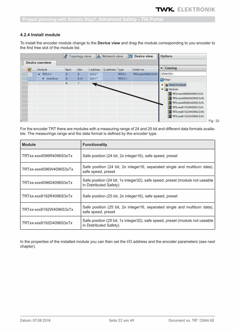
4.2.4 Install module
To install the encoder module change to the Device view and drag the module corresponding to you encoder to the first free slot of the module list.
For the encoder TRT there are modules with a measuring range of 24 and 25 bit and different data formats availa-ble. The measurings range and the data format is defined by the encoder type.
Module Functionality
TRTxx-xxx4096R4096S3xTx Safe position (24 bit, 2x integer16), safe speed, preset
TRTxx-xxx4096W4096S3xTx Safe position (24 bit, 2x integer16, separated single and multiturn data), safe speed, preset
TRTxx-xxx4096D4096S3xTx Safe position (24 bit, 1x integer32), safe speed, preset (module not useable in Distributed Safety)
TRTxx-xxx8192R4096S3xTx Safe position (25 bit, 2x integer16), safe speed, preset
TRTxx-xxx8192W4096S3xTx Safe position (25 bit, 2x integer16, separated single and multiturn data), safe speed, preset
TRTxx-xxx8192D4096S3xTx Safe position (25 bit, 1x integer32), safe speed, preset (module not useable in Distributed Safety)
In the properties of the installed module you can then set the I/O address and the encoder parameters (see next chapter).
Fig.: 22

Datum: 07.08.2018 Seite 23 von 49 Document no. TRT 12846 KE
Project planning with Simatic Step7, Advanced Safety - TIA Portal
4.2.5 Setting the network data
Select the encoder in the Device view to show the properties of the PROFINET interface of the TRT/S3.
4.2.5.1 Setting the PROFINET / PROFIsafe Adresse
Under "General" enter the PROFINET name which must be unique throughout the network to identify the device. If Generate PROFINET device name automatically is selected the name which is entered under PROFINET interface - General will be registered here. The default name is TRTS3-1.
In the TRT/S3, the Profisafe address must be added to the name. To do this, attach a number between 1 and 65,535 to the end (a special separator between the Profinet name and Profisafe address is not necessary). This must then be entered for F_Dest_Add under the F parameters (see Chapter 4.2.6.3).
The name assigned here must either be manually allocated to the absolute encoder (see Chapter 4.2.8) or it can be assigned automatically by the controller using the topology editor (see Chapter 4.2.7 Planning of "Device exchange without programming device" and "Automatic commissioning").
The device name is stored in the absolute encoder, where it is protected against zero voltage. An installed device can be exchanged with a brand new device without a programming device or exchanging a memory card. The correct name is automatically assigned to the new absolute encoder by the controller. To do this, however, the prerequisites under Chapter 4.2.7 have to be met.
Fig.: 23

Datum: 07.08.2018 Seite 24 von 49 Document no. TRT 12846 KE
Project planning with Simatic Step7, Advanced Safety - TIA Portal
4.2.5.2 IP-Adresse
Under "PROFINET interface - Ethernet addresses - IP protocol" the boxes Use IP protocol and Set IP address in the project should be checked. Step7 automatically assigns an IP address when inserting the device in the project. Manually setting of the IP address is also possible.
4.2.5.3 Prioritized startup, media redundancy, update time and synchronisation
Via the interface option Prioritized startup the startup time of the TRT/S3 from power on until PROFINET I/O data exchange can be reduced from approx. 10s to 5s. However, this can only be achieved as of the second startup.
The TRT/S3 can be used as member (client) in a redundant ring. In case of a line topology one network cable from the last client to the controler (manager) is necessary only to achieve a redundant communication. Bevor setting the media redundancy role of the TRT/S3 a MRP domain has to be created and the MRP manager (nor-mally the controler) to be assigned.
Under "PROFINET interface", "Advanced options", "Real time settings" the desired Update time of the TRT/S3 can be set. The possible values depend on the setting of the send clock of the CPU. The minimal update time for the TRT/S3 is 250 µs.
The desired real time class can be set under Synchronisation. The TRT/S3 supports the classes RT and IRT.
4.2.6 Setting the absolute encoder (properties of the module)
4.2.6.1 Setting the I/O address
After switching to the device view of the TRT/S3 and selecting slot 1 in the device overview the properties of the module can be accessed.
Set the PLC addresses for the input data (position, speed and status word) and for the output data (preset and control word) under I/O addresses (see Chapter 5 for the data format).
Fig.: 24

Datum: 07.08.2018 Seite 25 von 49 Document no. TRT 12846 KE
Project planning with Simatic Step7, Advanced Safety - TIA Portal
4.2.6.2 Parameterising the absolute encoder
The absolute encoder's parameters can be changed in the "Module parameters" tab. An explanation of the para-meters can be found in Chapter 6. After changing the encoder parameters the checksum has to be re-calculated and entered under the F-parameters (see next chapter).
4.2.6.3 Setting the F parameters
The F parameters must be set in the "PROFIsafe" tab. Here, you have to set the Profisafe address attached to the Profinet name under "F_Dest_Add" and to specify a watchdog time corresponding to your system under "F_WD_Time"or you to take over the automatic setting . "F_Source_Add" is assigned automatically by the S7
At the bottom of this window you can see the number and the symbolic name of the F-IO data block of this en-coder assigned by Step7.
Fig.: 25
Fig.: 26
Datum: 07.08.2018 Seite 26 von 49 Document no. TRT 12846 KE
Project planning with Simatic Step7, Advanced Safety - TIA Portal
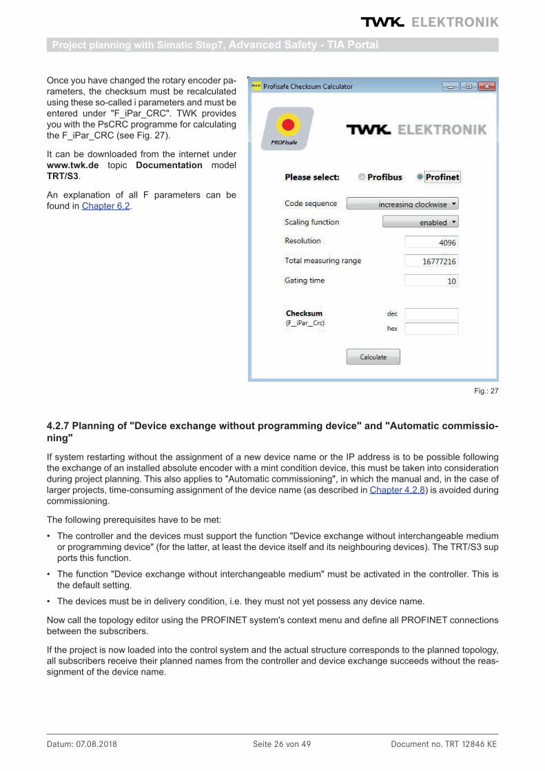
Once you have changed the rotary encoder pa-rameters, the checksum must be recalculated using these so-called i parameters and must be entered under "F_iPar_CRC". TWK provides you with the PsCRC programme for calculating the F_iPar_CRC (see Fig. 27).
It can be downloaded from the internet under www.twk.de topic Documentation model TRT/S3.
An explanation of all F parameters can be found in Chapter 6.2.
Fig.: 27
4.2.7 Planning of "Device exchange without programming device" and "Automatic commissio-ning"
If system restarting without the assignment of a new device name or the IP address is to be possible following the exchange of an installed absolute encoder with a mint condition device, this must be taken into consideration during project planning. This also applies to "Automatic commissioning", in which the manual and, in the case of larger projects, time-consuming assignment of the device name (as described in Chapter 4.2.8) is avoided during commissioning.
The following prerequisites have to be met:
• The controller and the devices must support the function "Device exchange without interchangeable medium or programming device" (for the latter, at least the device itself and its neighbouring devices). The TRT/S3 sup ports this function.
• The function "Device exchange without interchangeable medium" must be activated in the controller. This is the default setting.
• The devices must be in delivery condition, i.e. they must not yet possess any device name.
Now call the topology editor using the PROFINET system's context menu and define all PROFINET connections between the subscribers.
If the project is now loaded into the control system and the actual structure corresponds to the planned topology, all subscribers receive their planned names from the controller and device exchange succeeds without the reas-signment of the device name.

Datum: 07.08.2018 Seite 27 von 49 Document no. TRT 12846 KE
Project planning with Simatic Step7, Advanced Safety - TIA Portal
4.2.8 Assignment of the device name
If a PROFINET topology has not been defined as described in Chapter 4.2.7 or if the prerequisites for automatic commissioning are not met, the absolute encoder name must be assigned manually.With the absolute encoder connected and the programming device connected to the control system, select "Assign device name" in the context menu of the PROFINET.
Subsequently the window "Assign PROFINET device name" appears. After selecting the correct online connec-tion the accessible devices will be displayed. This for example could look like shown in figure 29.
Fig.: 28
Fig.: 29

Datum: 07.08.2018 Seite 28 von 49 Document no. TRT 12846 KE
Project planning with Simatic Step7, Advanced Safety - TIA Portal
It can be seen that the absolute encoder device type "TWK T series" does not possess either a valid IP address or a name. Now mark the absolute encoder, check the name proposed at the top of the window and click on "assign name."
The device name is then stored in the absolute encoder, where it is protected against zero voltage.
The absolute encoder now logs onto the controller with its device name and is then provided with a valid IP address by the controller. This is also stored in the absolute encoder, where it is protected against zero voltage.
4.2.9 Resetting to the factory settings
After going online the online diagnosis is available via the context menu of the TRT/S3. Under "Functions" the function "Reset to factory settings" is available.
The following encoder data will be reset as follows:
The following are reset Delivery condition
Parameters See Chapter 6.1 for default values
Offset 0 (i.e. the preset setting is undone)
Device name Empty
IP-parameters All 0
I&M0-revision counter 0
After resetting, the connection to the profinet controller is closed and the NS LED lights up red. After switching the voltage off/on, the connection can be re-established by assigning the device name.
If the connections have been defined using the topology editor, the TRT/S3 restarts automatically with the name assigned during project planning.
Fig.: 30

Datum: 07.08.2018 Seite 29 von 49 Document no. TRT 12846 KE
Project planning with Simatic Step7
4.3 Application program
4.3.1 Remarks
For a detailed documentation for project planning and programming of F programs refer to SIMATIC S7 Distribut-ed Safety - Project Planning and Programming, Programming and Operating Manual (A5E00109536-03) /7/ and SIMATIC S7 Distributed Safety Getting Started /8/ respectivly SIMATIC Safety - Project Planning and Program-ming /9/ und SIMATIC Safety Getting Started /10/ when using Safety Advance in the TIA-Portal.
4.3.2 F-Peripherie-DB
On translation of the hardware configuration, an F periphery DB is generated for the absolulute encoder, as for each other Profisafe subscriber. The automatically generated name consists of the I/O address and the module name.
The F periphery DB contains the for the operation of the encoder necessary variables. It has the following appearance: (A detailed description can be found in the documentation mentioned above)
Distributed Safety
Safety Advance
4.3.3 Accessing the encoder in the F program
Important for the fail safe operation of the encoder are: reintegration after communication or F periphery errors by the variables „ACK_REQ“ and "ACK_REI" or "ACK_GL", evaluation of the failsafe status by the variable "QBAD" and the evaluation of the diagnostic data by the variable "DIAG". All mentioned variables are provided by the F periphery DB. An example can be found in the following example program.
The access to the I/O data of the encoder is different and depending on the output code of the encoder and on the S7 software package. Because in Distributed Safety the use of double words in the safety program is prohi-
Datum: 07.08.2018 Seite 30 von 49 Document no. TRT 12846 KE
Project planning with Simatic Step7
bited in this case, only word access to the 32 bit position and reference value is possible, that means the position and the reference value are devided into 2 words each and the evalutation has to be done seperately. For this use encoder with output code "R" and "W" are provided.
In the safety program of TIA Safety Advanced doublewords can be used now. Thus position and reference value in data type DINT32 can be treated in the same way as in the standard program. For this use encoder with output code "D" are provided. For a description of the data format see chapter 5.
4.3.4 Example program
The following example shows how to access the position and speed value as well as the F periphery DB of the Profisafe absolute encoder in the safety programme. Setting a preset value and reading the diagnosis data is also demonstrated.
Only the programming steps which refer to the TWK absolute encoder are shown here. Knowledge regarding the programming and sequence of the failsafe S7 programme is assumed. As an introduction to failsafe program-ming, we recommend „SIMATIC S7 Distributed Safety - Getting Started“ /8/ and „SIMATIC S7 Distributed Safety – Project Planning and Programming“ /7/ respectively SIMATIC Safety - Project Planning and Programming /9/ and SIMATIC Safety Getting Started /10/ when using Safety Advance under TIA-Portal.
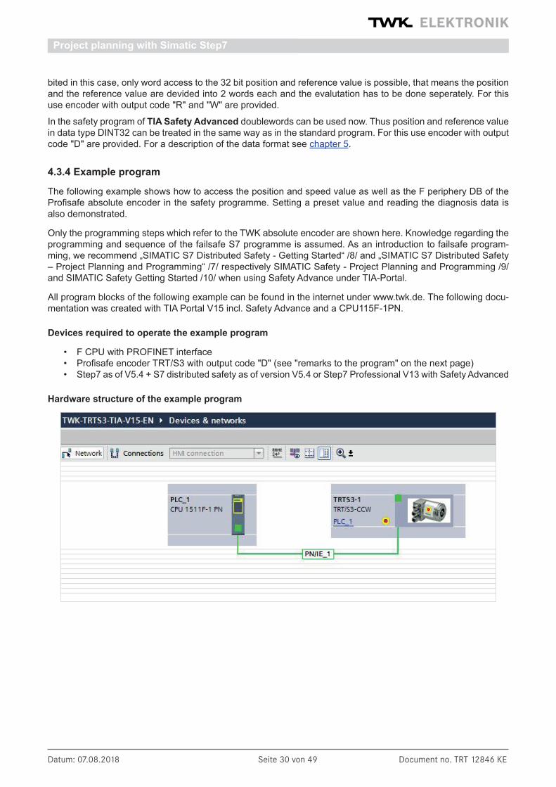
All program blocks of the following example can be found in the internet under www.twk.de. The following docu-mentation was created with TIA Portal V15 incl. Safety Advance and a CPU115F-1PN.
Devices required to operate the example program
• F CPU with PROFINET interface • Profisafe encoder TRT/S3 with output code "D" (see "remarks to the program" on the next page) • Step7 as of V5.4 + S7 distributed safety as of version V5.4 or Step7 Professional V13 with Safety Advanced
Hardware structure of the example program
Datum: 07.08.2018 Seite 31 von 49 Document no. TRT 12846 KE
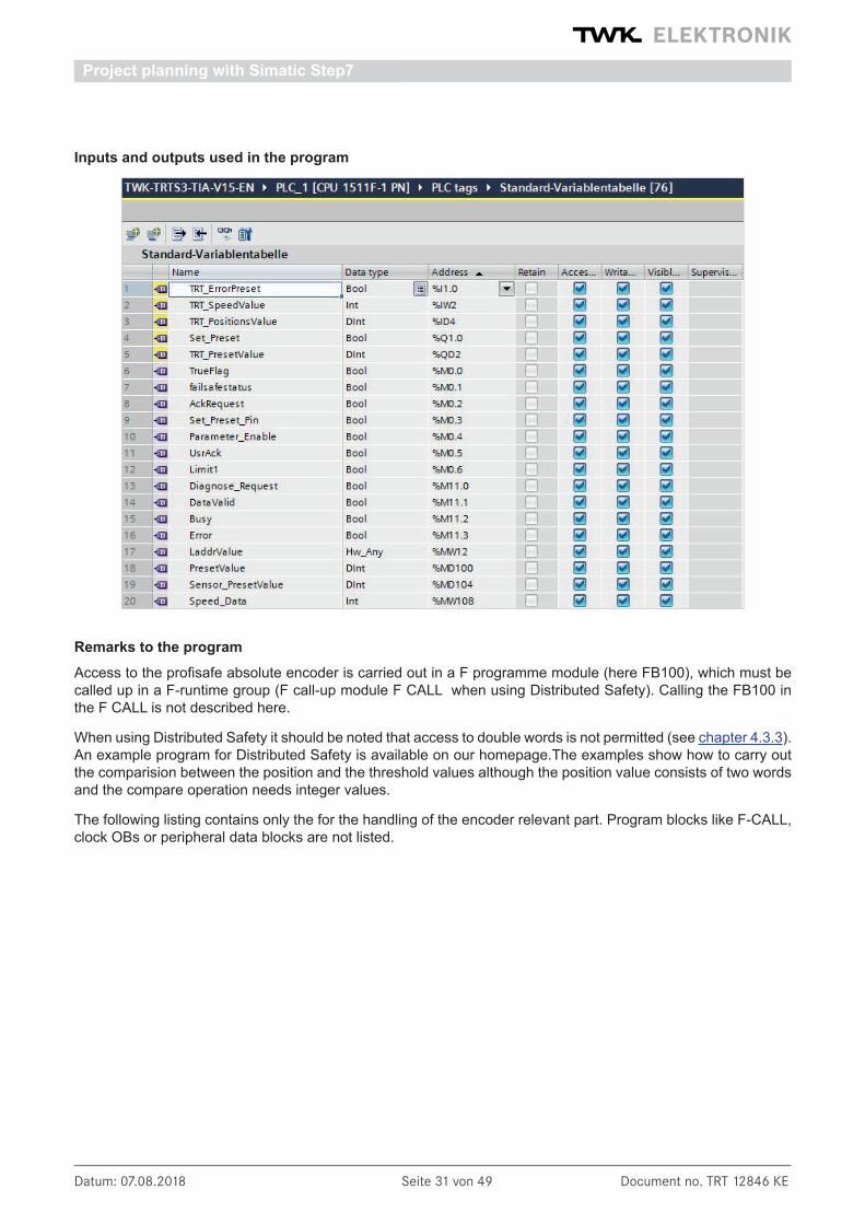
Inputs and outputs used in the program
Remarks to the programAccess to the profisafe absolute encoder is carried out in a F programme module (here FB100), which must be called up in a F-runtime group (F call-up module F CALL when using Distributed Safety). Calling the FB100 in the F CALL is not described here.
When using Distributed Safety it should be noted that access to double words is not permitted (see chapter 4.3.3). An example program for Distributed Safety is available on our homepage.The examples show how to carry out the comparision between the position and the threshold values although the position value consists of two words and the compare operation needs integer values.
The following listing contains only the for the handling of the encoder relevant part. Program blocks like F-CALL, clock OBs or peripheral data blocks are not listed.
Project planning with Simatic Step7
Datum: 07.08.2018 Seite 32 von 49 Document no. TRT 12846 KE
Project planning with Simatic Step7
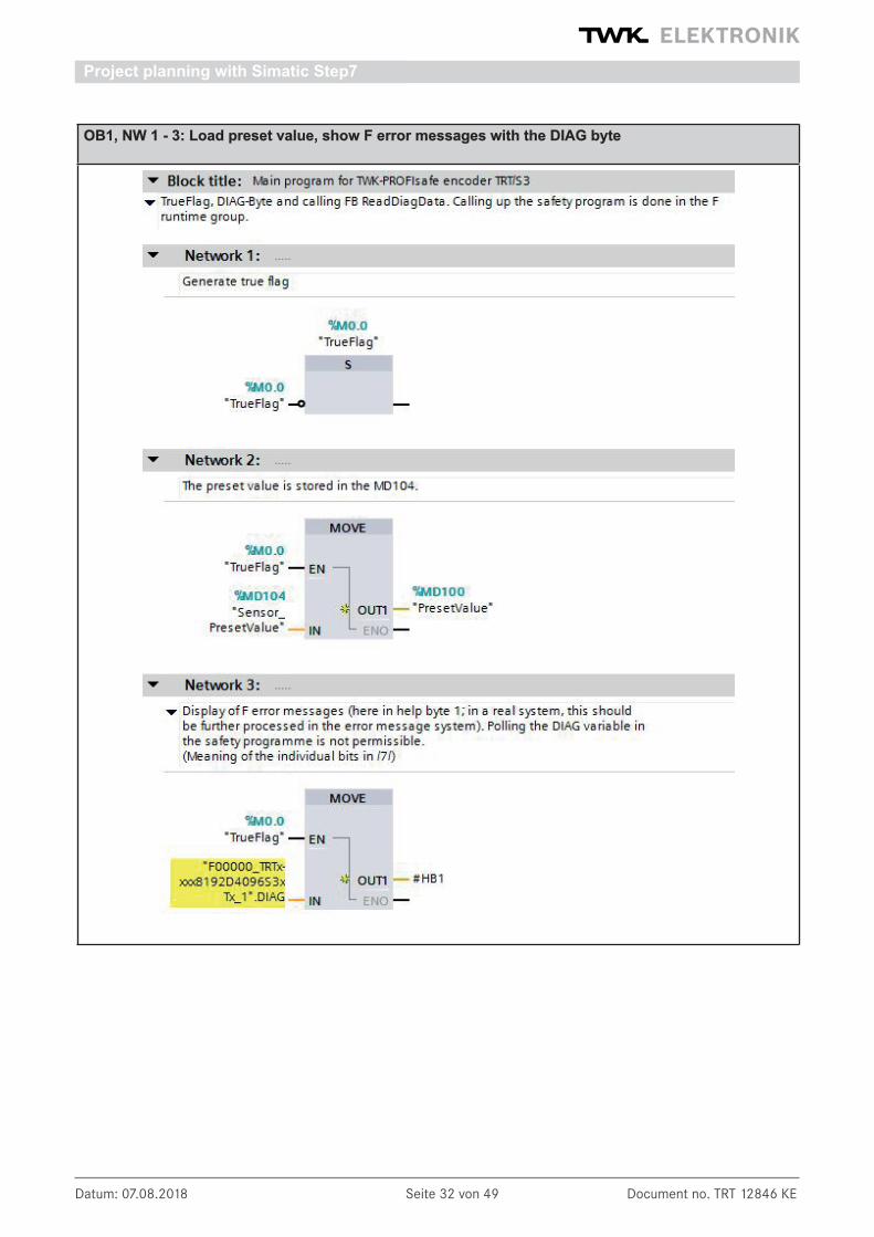
OB1, NW 1 - 3: Load preset value, show F error messages with the DIAG byte

Datum: 07.08.2018 Seite 33 von 49 Document no. TRT 12846 KE
Project planning with Simatic Step7
FB100, NW 1 - 3: Reading QBAD and Acknowledge

Datum: 07.08.2018 Seite 34 von 49 Document no. TRT 12846 KE
FB100, NW 4 - 6: Set reference value
Project planning with Simatic Step7

Datum: 07.08.2018 Seite 35 von 49 Document no. TRT 12846 KE
FB100, NW 7 - 8: Accessing position and velocity
Project planning with Simatic Step7

Datum: 07.08.2018 Seite 36 von 49 Document no. TRT 12846 KE
Reading the diagnosis data
On occurrence of a PROFINET device diagnostic alarm, OB 82 is run through in S7. Amongst other aspects, the trigger for the diagnostic alarm can be ascertained in this. The diagnostic data can then be read-out with SFB52 which has to be called in the cyclic program. The events which trigger a diagnostic alarm in the absolute encoder can be found in Chapter 7.2.
The control system transfers the hardware identifier of the device which has transmitted the diagnostic alarm in the local variable LADDR.
OB 82: Evaluation of the local OB 82 data and initialisation of the read job
OB 1, NW 4: Calling the FB 1 to read the diagnostic data
Project planning with Simatic Step7

Datum: 07.08.2018 Seite 37 von 49 Document no. TRT 12846 KE
FB 2: Reading the diagnostic data with the SFB52 RDREC
Project planning with Simatic Step7
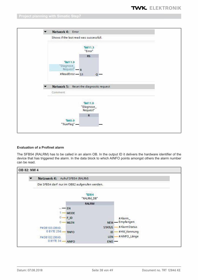
Datum: 07.08.2018 Seite 38 von 49 Document no. TRT 12846 KE
Project planning with Simatic Step7
Evaluation of a Profinet alarm
The SFB54 (RALRM) has to be called in an alarm OB. In the output ID it delivers the hardware identifier of the device that has triggered the alarm. In the data block to which AINFO points amongst others the alarm number can be read.
OB 82: NW 4
Datum: 07.08.2018 Seite 39 von 49 Document no. TRT 12846 KE
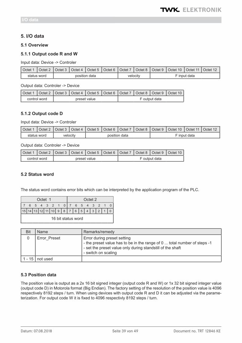
5. I/O data
5.1 Overview
5.1.1 Output code R and W
Input data: Device -> Controler
Octet 1 Octet 2 Octet 3 Octet 4 Octet 5 Octet 6 Octet 7 Octet 8 Octet 9 Octet 10 Octet 11 Octet 12status word position data velocity F input data
Output data: Controler -> Device
Octet 1 Octet 2 Octet 3 Octet 4 Octet 5 Octet 6 Octet 7 Octet 8 Octet 9 Octet 10control word preset value F output data
5.1.2 Output code D
Input data: Device -> Controler
Octet 1 Octet 2 Octet 3 Octet 4 Octet 5 Octet 6 Octet 7 Octet 8 Octet 9 Octet 10 Octet 11 Octet 12status word velocity position data F input data
Output data: Controler -> Device
Octet 1 Octet 2 Octet 3 Octet 4 Octet 5 Octet 6 Octet 7 Octet 8 Octet 9 Octet 10control word preset value F output data
5.2 Status word
The status word contains error bits which can be interpreted by the application program of the PLC.
Octet 1 Octet 27 6 5 4 3 2 1 0 7 6 5 4 3 2 1 0
15 14 13 12 11 10 9 8 7 6 5 4 3 2 1 0
16 bit status word
Bit Name Remarks/remedy0 Error_Preset Error during preset setting
- the preset value has to be in the range of 0 ... total number of steps -1 - set the preset value only during standstill of the shaft - switch on scaling
1 - 15 not used
5.3 Position data
The position value is output as a 2x 16 bit signed integer (output code R and W) or 1x 32 bit signed integer value (output code D) in Motorola format (Big Endian). The factory setting of the resolution of the position value is 4096 respectively 8192 steps / turn. When using devices with output code R and D it can be adjusted via the parame-terization. For output code W it is fixed to 4096 respectivly 8192 steps / turn.
I/O data

Datum: 07.08.2018 Seite 40 von 49 Document no. TRT 12846 KE
5.3.1 Data format coding R
Octet 3 Octet 4 Octet 5 Octet 67 6 5 4 3 2 1 0 7 6 5 4 3 2 1 0 7 6 5 4 3 2 1 0 7 6 5 4 3 2 1 0
31 30 29 28 27 26 25 24 23 22 21 20 19 18 17 16 15 14 13 12 11 10 9 8 7 6 5 4 3 2 1 0
0 0 0 0 0 0 0 position value *1 position value *1
0 0 0 0 0 0 0 0 position value *2 position value *1
*1 TRTxx-xxx8192R4096S3xTxx *2 TRTxx-xxx4096R4096S3xTxx
5.3.2. Data format coding W
The rotary encoders with code type W (TRTxx-xxxxxxxW4096S3xTxx) reveal deviating position and preset value representation. In these models, the number of revolutions (multiturn part) is output in the first word and the steps of the single-turn part in the second word
Octet 3 Octet 4 Octet 5 Octet 67 6 5 4 3 2 1 0 7 6 5 4 3 2 1 0 7 6 5 4 3 2 1 0 7 6 5 4 3 2 1 0
31 30 29 28 27 26 25 24 23 22 21 20 19 18 17 16 15 14 13 12 11 10 9 8 7 6 5 4 3 2 1 0
0 0 0 0 number of turns 0 0 0 steps *1
0 0 0 0 number of turns 0 0 0 0 steps *2
*1 TRTxx-xxx8192W4096S3xTxx *2 TRTxx-xxx4096W4096S3xTxx
5.3.3 Data format coding D
Encoder with the output code D (TRTxx-xxxxxxxD4096S3xTxx) provide a position- und preset representation as double word (Integer32).
Octet 5 Octet 6 Octet 7 Octet 87 6 5 4 3 2 1 0 7 6 5 4 3 2 1 0 7 6 5 4 3 2 1 0 7 6 5 4 3 2 1 0
31 30 29 28 27 26 25 24 23 22 21 20 19 18 17 16 15 14 13 12 11 10 9 8 7 6 5 4 3 2 1 0
0 0 0 0 0 0 0 position value *1
0 0 0 0 0 0 0 0 position value *2
*1 TRTxx-xxx8192D4096S3xTxx *2 TRTxx-xxx4096D4096S3xTxx
5.4 Velocity
The velocity value is determined via the cyclically read-in of the position data. The dimension is steps per gating time. The gating time (time interval for determining the change of position) is adjustable in the range of 10 - 1000 ms. The default value is 10 ms.
Coding R, W Octet 7 Octet 8Coding D Octet 3 Octet 4
7 6 5 4 3 2 1 0 7 6 5 4 3 2 1 0
15 14 13 12 11 10 9 8 7 6 5 4 3 2 1 0
16 bit velocity
I/O data

Datum: 07.08.2018 Seite 41 von 49 Document no. TRT 12846 KE
The speed value is output as a 16-bit signed integer value in Motorola format (Big-Endian). The following applies to the prefix: positive for increasing position negative for decreasing position
The refresh rate of the velocity signal is independent from the selected gating time always 1ms.
The speed measurement resolution is independent of the resolution set for the position value (resolution parame-ter). It is always based on a resolution of 4096 steps per revolution.
The steps/gating time unit can be converted to rpm as follows:
u =v x 60000 / t v = encoder output for speed value
4096 t = gating time in msu = speed in rpm
5.5 F input data
The 4-byte F input data consist of the 1-byte F status and the 3-byte CRC checksum. Their content is defined in the Profisafe profile /1/. The status of the F status bit must be evaluated in the F application programme (see programme example in Chapter 4.3.4).
5.6 Control word
Octet 7 Octet 87 6 5 4 3 2 1 0 7 6 5 4 3 2 1 0
15 14 13 12 11 10 9 8 7 6 5 4 3 2 1 0
16 bit control word
Bit Name Meaning0 Set_Preset The preset value is activated on the rising edge.
1 - 15 not used
5.7 Preset value (reference value)
In certain cases, setting the reference value is unavoidable in order to compare the machine position values and the absolute position of the absolute encoder. The reference value is the position value which is displayed at the reference point. The user must note that the reference value must lie within the range of 0 to (total number of steps - 1). This particularly has to be taken into consideration when changing the total number of steps.
The set reference value (preset value) function can only be executed whilst the absolute encoder shaft is stationary! Setting the reference value is only possible when scaling is switched on (see Chapter 6)!
The preset value is set in the cyclical I/O data traffic by transferring the preset value in the output bytes (octets 3 - 6) and subsequently (or simultaneously) setting bit 0 of the control word (octets 1 - 2).
Before setting the preset value, the i parameterization must be enabled with the F control bit iPar_EN. The rotary encoder reports the completion of the process with the F status bit iPar_OK. If an error occurs on setting the preset value, e.g. due to a rotating rotary encoder shaft, this is reported via status bit 0 in the status word. In both cases, i.e. in the case of successful preset and in the event of an error, the iPar_EN bit must be reset. The rotary encoder then resets its iPAR_OK to zero. (See programme example in Chapter 4.3.4.)
The preset value is taken over with the rising edge of bit 0 of the contorl word. An offset value is calculated (from the current actual position and the reference value) by the absolute encoder in this case. This is stored in the ab-solute encoder, where it is protected against zero voltage, with the result that the new position is correctly output again even following voltage failure.
I/O data

Datum: 07.08.2018 Seite 42 von 49 Document no. TRT 12846 KE
5.7.1 Data format coding R
Octet 3 Octet 4 Octet 5 Octet 67 6 5 4 3 2 1 0 7 6 5 4 3 2 1 0 7 6 5 4 3 2 1 0 7 6 5 4 3 2 1 0
31 30 29 28 27 26 25 24 23 22 21 20 19 18 17 16 15 14 13 12 11 10 9 8 7 6 5 4 3 2 1 0
0 0 0 0 0 0 0 preset value *1 preset value *1
0 0 0 0 0 0 0 0 preset value *2 preset value *2
*1 TRTxx-xxx8192R4096S3xTxx *2 TRTxx-xxx4096R4096S3xTxx
5.7.2. Data format coding W
Octet 3 Octet 4 Octet 5 Octet 67 6 5 4 3 2 1 0 7 6 5 4 3 2 1 0 7 6 5 4 3 2 1 0 7 6 5 4 3 2 1 0
31 30 29 28 27 26 25 24 23 22 21 20 19 18 17 16 15 14 13 12 11 10 9 8 7 6 5 4 3 2 1 0
0 0 0 0 preset value number of turns 0 0 0 preset value steps *1
0 0 0 0 preset value number of turns 0 0 0 0 preset value steps *2
*1 TRTxx-xxx8192R4096S3xTxx *2 TRTxx-xxx4096R4096S3xTxx
5.7.3 Data format coding D
Octet 3 Octet 4 Octet 5 Octet 67 6 5 4 3 2 1 0 7 6 5 4 3 2 1 0 7 6 5 4 3 2 1 0 7 6 5 4 3 2 1 0
31 30 29 28 27 26 25 24 23 22 21 20 19 18 17 16 15 14 13 12 11 10 9 8 7 6 5 4 3 2 1 0
0 0 0 0 0 0 0 preset value *1
0 0 0 0 0 0 0 0 preset value *2
*1 TRTxx-xxx8192D4096S3xTxx *2 TRTxx-xxx4096D4096S3xTxx
5.8 F output data
The 4-byte F output data consist of 1 control byte and the 3-byte CRC checksum. Their content is defined in the Profisafe profile /1/. The F control bits are made available by the F control system and must be implemented in the F application program (see programme example Chapter 4.3.4).
I/O data
Datum: 07.08.2018 Seite 43 von 49 Document no. TRT 12846 KE
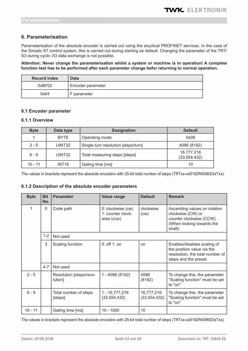
6. ParameterisationParameterisation of the absolute encoder is carried out using the acyclical PROFINET services. In the case of the Simatic S7 control system, this is carried out during starting as default. Changing the parameter of the TRT/S3 during cyclic I/O data exchange is not possible.
Attention: Never change the parameterisation whilst a system or machine is in operation! A complete function test has to be performed after each parameter change befor returning to normal operation.
Record index Data0xBF02 Encoder parameter
0x64 F parameter
6.1 Encoder parameter
6.1.1 Overview
Byte Data type Designation Default1 BYTE Operating mode 0x08
2 - 5 UINT32 Single turn resolution [steps/turn] 4096 (8192)
6 - 9 UINT32 Total measuring steps [steps] 16.777.216 (33.554.432)
10 - 11 INT16 Gating time [ms] 10
The values in brackets represent the absolute encoders with 25-bit total number of steps (TRTxx-xx8192R4096S3xTxx).
6.1.2 Description of the absolute encoder parameters
Byte Bit No.
Parameter Value range Default Remark
1 0 Code path 0: clockwise (cw)1: counter clock-wise (ccw)
clockwise (cw)
Ascending values on rotationclockwise (CW) orcounter clockwise (CCW).(When looking towards the shaft)
1-2 Not used
3 Scaling function 0: off 1: on on Enables/disables scaling of the position value via the resolutioin, the total number of steps and the preset.
4-7 Not used
2 - 5 Resolution [steps/revo-lution]
1 - 4096 (8192) 4096(8192)
To change this, the parameter"Scaling function" must be setto "on"
6 - 9 Total number of steps[steps]
1 - 16,777,216 (33,554,432)
16,777,216(33,554,432)
To change this, the parameter"Scaling function" must be setto "on"
10 - 11 Gating time [ms] 10 - 1000 10
The values in brackets represent the absolute encoders with 25-bit total number of steps (TRTxx-xx8192R4096S3xTxx).
Parameterisation

Datum: 07.08.2018 Seite 44 von 49 Document no. TRT 12846 KE
Notes:Coding:All values in Motorola format (Big Endian)
ResolutionThe resolution of encoders with coding W is not changeable and factory set to 4096 respectivly 8192 for the 25 bit encoder.
Gesamtschrittzahl:Total number of steps:It must be noted that the number of revolutions is calculated in powers of 2n internally in the encoder. Irrespec-tive of this requirement, the user can programme the desired total number of steps and the desired resolution according to the application. During calculation, the absolute encoder uses the next highest power of 2n if ne-cessary. In this case, the values are designated as the effective resolution or the effective total number of steps and are displayed as the output values.
Example : Desired total number of steps: 20,480 Desired resolution: 4096 Desired number of revolutions: 5 Internal absolute encoder calculation Effective total number of steps: 32,768 Effective resolution: 4096 Calculated number of revolutions: 8
(Note: The above notice is to be taken into consideration in the case of non-reversible operation. In the listed example, position 0 is only reached after 32,767 steps and not after 20,479 steps as desired.)
6.2 F parameter
6.2.1 Overview
OverviewOctet Data type Description Default
1 Unsigned8 F_Prm_Flag1
2 Unsigned8 F_Prm_Flag2
3-4 Unsigned16 F_Source_Add 0
5-6 Unsigned16 F_Dest_Add 1
7-8 Unsigned16 F_WD_Time 120
9-12 Unsigned32 F_iPar_CRC 7100
13-14 Unsigned16 F_Par_CRC -----
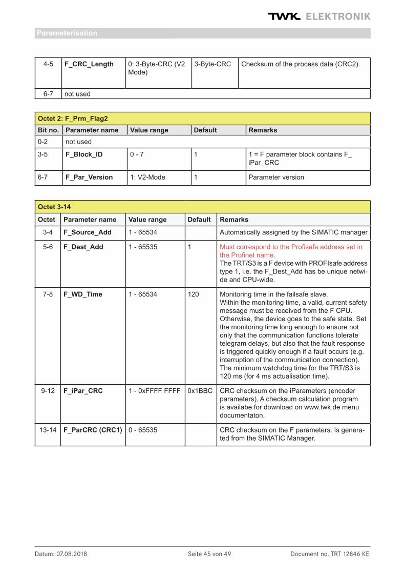
6.2.2 Description of the F parameters
Octet 1: F_Prm_Flag1Bit no. Parameter name Value range Default Remarks
0 F_Check_SeqNr 0: NoCheck NoCheck Fixed to "No Check"
1 F_Check_iPar 0: NoCheck NoCheck Fixed to "No Check"
2-3 F_SIL 1: SIL2 SIL2 Fixed to "SIL2"
Parameterisation
Datum: 07.08.2018 Seite 45 von 49 Document no. TRT 12846 KE
4-5 F_CRC_Length 0: 3-Byte-CRC (V2 Mode)
3-Byte-CRC Checksum of the process data (CRC2).
6-7 not used
Octet 2: F_Prm_Flag2Bit no. Parameter name Value range Default Remarks0-2 not used
3-5 F_Block_ID 0 - 7 1 1 = F parameter block contains F_iPar_CRC
6-7 F_Par_Version 1: V2-Mode 1 Parameter version
Octet 3-14
Octet Parameter name Value range Default Remarks
3-4 F_Source_Add 1 - 65534 Automatically assigned by the SIMATIC manager
5-6 F_Dest_Add 1 - 65535 1 Must correspond to the Profisafe address set in the Profinet name.The TRT/S3 is a F device with PROFIsafe address type 1, i.e. the F_Dest_Add has be unique netwi-de and CPU-wide.
7-8 F_WD_Time 1 - 65534 120 Monitoring time in the failsafe slave.Within the monitoring time, a valid, current safety message must be received from the F CPU. Otherwise, the device goes to the safe state. Set the monitoring time long enough to ensure not only that the communication functions tolerate telegram delays, but also that the fault response is triggered quickly enough if a fault occurs (e.g. interruption of the communication connection).The minimum watchdog time for the TRT/S3 is 120 ms (for 4 ms actualisation time).
9-12 F_iPar_CRC 1 - 0xFFFF FFFF 0x1BBC CRC checksum on the iParameters (encoder parameters). A checksum calculation program is availabe for download on www.twk.de menu documentaton.
13-14 F_ParCRC (CRC1) 0 - 65535 CRC checksum on the F parameters. Is genera-ted from the SIMATIC Manager.
Parameterisation

Datum: 07.08.2018 Seite 46 von 49 Document no. TRT 12846 KE
7. Diagnostic
7.1 Overview
The encoder TRT/S3 provides diagnostic data in 3 different ways.
- LEDs (see Chapter 3.3)
- PROFINET alarms (see Chapter 7.2)
- Diagnostic data (see Chapter 7.3)
7.2 PROFINET alarms
The following alarms are send via the PROFINET alarm mechanism. In the PROFINET controler they are displa-yed in plain text and partially with a help text.
Erro no.(hex)
Error text Reaction Status-LED(NS)
Remarks/remedy
0x001A Internal communication error (TPS-1)
Input and F data = 0 Please switch power off/on or change the device
0x0040 Mismatch of safety destina-tion address (F_Dest_Add)
Diagnostic data: F para-meter error
red flashing(1 Hz)
0x0041 Safety destination address not valid (F_Dest_Add)
Diagnostic data: F para-meter error
red flashing(1 Hz)
0x0042 Safety source address not valid (F_Source_Add)
Diagnostic data: F para-meter error
red flashing(1 Hz)
0x0043 Safety watchdog time va-lue is 0 ms(F_WD_Time)
Diagnostic data: F para-meter error
red flashing(1 Hz)
0x0044 Parameter "F_SIL" ex-ceeds SIL from specific device application
Diagnostic data: F para-meter error
red flashing(1 Hz)
0x0045 Parameter "F_CRC_Length" does not match the generated values
Diagnostic data: F para-meter error
red flashing(1 Hz)
0x0046 Version of F-Parameter set incorrect (F_Par_Version)
Diagnostic data: F para-meter error
red flashing(1 Hz)
0x0047 F parameter CRC error (CRC1-Fault)
Diagnostic data: F para-meter error
red flashing(1 Hz)
0x0048 Error in F parameterset Diagnostic data: F para-meter error
red flashing(1 Hz)
0x004B Inconsistent iParameters (iPar-CRC error)
Diagnostic data: F para-meter error
red flashing(1 Hz)
Please check the value of the F parameter F-iPar-CRC.
0x1100 Device error Diagnostic data: device error F status word:FV_activated, Device_Fault
fast red flashing (10 Hz)
Please switch power off/on or change the device.
0x1110 Preset error Diagnostic data: Preset errorStatus word: Error-Preset
red flashing (1 Hz)
The preset value has to be in the range of 0 ... total number of steps -1. Setting the preset is only allowed when the shaft is in standstill. Scaling has to be on.
Diagnostic

Datum: 07.08.2018 Seite 47 von 49 Document no. TRT 12846 KE
0x1120 Velocity measuring range exceeded
Diagnostic data: velocity error F status word:FV_activated
red flashing (1 Hz)
Please reduce the velocity or decrease the gating time.
0x1140 Parameter error Diagnostic data: Parameter error
red flashing (1 Hz)
The value for the total measuring range has to be in the range of: resolution ... (resolution x max. number of turns (4096)).
0x1150 Supply voltage out of range F status word:FV_activated, Device_Fault
red flashing (1 Hz)
Please check the supply voltage and switch power supply off/on.
0x1160 Wrong Record Index on startup
F status word:FV_activated, Device_Fault
red flashing (1 Hz)
Please check your GSD file.
0x1170 Sensor not ready F status word:FV_activated, Device_Fault
red flashing (1 Hz)
Please switch power off/on or change the device.
7.3 Diagnostic data records
The following diagnostic records are available in the TRT/S3. They can be read out with the PROFINET acyclic read services.
Record index Data
0xAFF0 I&M0 data (according to I&M-specification version 1.2 /9/)
0xBF02 Parameter data (see Chapter 6)
0xFDE9 Diagnostic data according to Encoder Class 2 Profile (see below)
7.3.1 Diagnostic data according to Encoder Class 2 Profile
Diagnosis data in data record 0xFDE9Byte Datatyp Diagnostic function Default
(values in hex)Diagnostic
alarm Remark
1 - 8 BYTE Reserved 009 BYTE Operating status 08 No CW,
Scaling on10 BYTE Encoder typ 01 No Absolute multiturn encoder
11 - 14 UINT32 Maximum resolution 0000.1000 (0000.2000)
No 4096 (8192) steps/revolu-tion
15 - 16 UINT16 Maximum measuring range 1000 No 4096 revolutions17 UINT8 Additional alarm messages 00 No Not supported
18 - 19 UINT16 Supported alarm messages 0000 No Not supported20 - 21 UINT16 Warning messages 0000 No Not supported22 - 23 UINT16 Supported warning messa-
ges0000 No Not supported
24 - 25 UINT16 Profile version 0101 No Current encoder profile version
Diagnostic
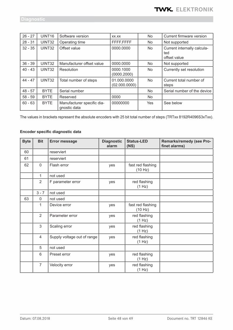
Datum: 07.08.2018 Seite 48 von 49 Document no. TRT 12846 KE
Diagnostic
26 - 27 UINT16 Software version xx.xx No Current firmware version28 - 31 UINT32 Operating time FFFF.FFFF No Not supported32 - 35 UINT32 Offset value 0000.0000 No Current internally calcula-
tedoffset value
36 - 39 UINT32 Manufacturer offset value 0000.0000 No Not supported40 - 43 UINT32 Resolution 0000.1000
(0000.2000)No Currently set resolution
44 - 47 UINT32 Total number of steps 01.000.0000(02.000.0000)
No Current total number of steps
48 - 57 BYTE Serial number No Serial number of the device58 - 59 BYTE Reserved 0000 No60 - 63 BYTE Manufacturer specific dia-
gnostic data00000000 Yes See below
The values in brackets represent the absolute encoders with 25 bit total number of steps (TRTxx 8192R4096S3xTxx).
Encoder specific diagnostic data
Byte Bit Error message Diagnostic alarm
Status-LED(NS)
Remarks/remedy (see Pro-finet alarms)
60 reserviert61 reserviert62 0 Flash error yes fast red flashing
(10 Hz)1 not used2 F parameter error yes red flashing
(1 Hz)3 - 7 not used
63 0 not used1 Device error yes fast red flashing
(10 Hz)2 Parameter error yes red flashing
(1 Hz)3 Scaling error yes red flashing
(1 Hz)4 Supply voltage out of range yes red flashing
(1 Hz)5 not used6 Preset error yes red flashing
(1 Hz)7 Velocity error yes red flashing
(1 Hz)

Datum: 07.08.2018 Seite 49 von 49 Document no. TRT 12846 KE
8. Scope of deliveryThe scope of delivery includes: - Absolute encoder with PROFIsafe interface
- Connection assignment TY XXXXX (depending on the device variant)
Available for download on www.twk.de are: - the corresponding datasheet
- this user manual
- the checksum calculation program PsCrc
- the certificates
- example programmes
- GSD file and bitmap
9. Literature/1/ PROFIsafe-Profile for Safety Technology, Order No. 3.092 und 3.192, PROFIBUS Nutzerorganisation e. V., Haid-und-Neu-Str. 7, D-76131 Karlsruhe, www.profibus.com
/2/ PROFINET - Interface nach IEC 61158 / 61784 bzw. PNO-Spezifikation, Order No. 2.712 und 2.722, PRO FIBUS Nutzerorganisation e. V., Haid-und-Neu-Str. 7, D-76131 Karlsruhe, www.profibus.com
/3/ PROFINET Installation guidline, Order No. 8.071, PROFIBUS Nutzerorganisation e. V., Haid-und-Neu-Str. 7, D-76131 Karlsruhe, www.profibus.com
/4/ PROFINET Cabling and Interconnection Technology, Order No.: 2.252, PROFIBUS Nutzerorganisation e. V., Haid-und-Neu-Str. 7, D-76131 Karlsruhe, www.profibus.com
/5/ Installation Guideline PROFINET Part2: Network Components, Order No.: 2.252 p2, PROFIBUS Nutzeror ganisation e. V., Haid-und-Neu-Str. 7, D-76131 Karlsruhe, www.profibus.com
/6/ PROFIsafe - Environmental Requirements related to PROFIsafe - Profile for Safety Technology on PROFI- BUS DP and PROFINET IO (IEC 61784-3-3), Order No. 2.232, PROFIBUS Nutzerorganisation e. V., Haid-und-Neu-Str. 7, D-76131 Karlsruhe, www.profibus.com
/7/ SIMATIC S7 Distributed Safety - Project Planning and Programming, Programming and Operating Manual (A5E00109536-03) - http://support.automation.siemens.com
/8/ SIMATIC S7 Distributed Safety Getting Started (A5E00320725-01) - http://support.automation.siemens.com
/9/ Profile Guidelines Part 1: Identification & Maintenance Functions, Order No. 3.502, www.profibus.com
/10/ SIMATIC Safety - Project Planning and Programming (A5E02714440-AC) - http://support.automation.siemens.com
/11/ SIMATIC Safety - Getting Started (A5E02714463-01) - http://support.automation.siemens.com
Scope of delivery, Literature