
Development status on the pyrochemistry R&D program at CEA
21
Development status on the pyrochemistry R&D program at CEA E. Mendes, H. Boussier, A. Laplace, J.F. Vigier, M. Miguirditchian 26-30/08/2012 Fontana (USA) IPRC 2012 | Eric Mendes, 17 OCTOBRE 2012 | PAGE 1 CEA | 10 AVRIL 2012 UO 2 PuO 2 DEN/DRCP/SCPS/LEPS IPRC | AUGUST 26 – 30 th 2012
Transcript of Development status on the pyrochemistry R&D program at CEA

Development status on the
pyrochemistry R&D program at CEA
E. Mendes, H. Boussier, A. Laplace, J.F. Vigier, M. Miguirditchian
26-30/08/2012 Fontana (USA)
IPRC 2012 | Eric Mendes,
17 OCTOBRE 2012 | PAGE 1CEA | 10 AVRIL 2012
UO2
PuO2
DEN/DRCP/SCPS/LEPS IPRC | AUGUST 26 – 30th 2012

Introduction
Outlines
Several spent fuel pyrochemical processes studied worldwide: Electrorefining/Electrolysis in molten chloride melts → most studied technique
Precipitation/Electrolysis assessed
Reductive extraction in molten chlorides also investigated
mainly as a step of the electrorefining complete process
Reference route developed by CEA: Reductive liquid/liquid extraction in fluoride media
France: only country currently considering this alternative route for fuel
reprocessing
17 OCTOBRE 2012 | PAGE 2DEN/DRCP/SCPS/LEPS IPRC | AUGUST 26 – 30th 2012
-LiF-AlF3 solvent at 830°C
- Al both solvent and reductor
AnF3(salt) + Al ↔ An(Al) + AlF3

Liquid/Liquid extraction process flowsheet
17 OCTOBRE 2012 | PAGE 3
Vitrification
FPFx
LiCl-CaCl2
AnO2
Al
LiF-AlF3 15-35%
AlCl3
Thermal
treatment
1100°C
Hydrofluorination
450-500°C
Precipitation/
Conversion
700°C
ZrF4
An
PF
An
Cs, Rb
Distillation
Used Fuel
ZnDigestion
830°C
Platinoïdes
Metallic
wasteDistillation
LiF-AlF3
Gas
Back
Extraction
700°CEXTRACTION
830°C
FP
Stripping
DEN/DRCP/SCPS/LEPS IPRC | AUGUST 26 – 30th 2012

Liquid/liquid extraction core of process
demonstration
17 OCTOBRE 2012
| PAGE 4
CEA | 10 AVRIL 2012
DEN/DRCP/SCPS/LEPS IPRC | AUGUST 26 – 30th 2012
Liquid/liquid extraction core of process demonstration 1/3
17 OCTOBRE 2012 | PAGE 5
(9 %) (42 %)
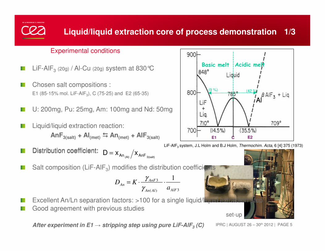
Basic melt Acidic melt
(9 %) (42 %)
Basic melt Acidic melt
LiF-AlF3 system, J.L Holm and B.J Holm, Thermochim. Acta, 6 [4] 375 (1973)
AlAl
E1 C E2
Experimental conditions
LiF-AlF3 (20g) / Al-Cu (20g) system at 830°C
Chosen salt compositions :
E1 (85-15% mol. LiF-AlF3), C (75-25) and E2 (65-35)
U: 200mg, Pu: 25mg, Am: 100mg and Nd: 50mg
Liquid/liquid extraction reaction:
AnF3(salt) + Al(met) ���� An(met) + AlF3(salt)
Distribution coefficient:3(salt)(Al) AnFAn xxD =
3)(
3 1
AlFAlAn
AnF
An
aKD ⋅⋅=
γ
γ
set-up
Distribution coefficient:
Salt composition (LiF-AlF3) modifies the distribution coefficients
Excellent An/Ln separation factors: >100 for a single liquid/liquid extraction step
Good agreement with previous studies
After experiment in E1 → stripping step using pure LiF-AlF3 (C)

DEN/DRCP/SCPS/LEPS IPRC | AUGUST 26 – 30th 2012
An oxidative liquid/liquid back-extraction step:
In chloride media, using oxidizing reagent → AlCl3
An(met) + AlCl3(salt) ���� AnCl3(salt) + Al(met)
From previous studies, optimal operating conditions:
LiCl-CaCl2 (30-70 mol.%) at 700°C (4h experiment)
Reagent NaAlCl4 , overstoechiometry: 7 (stabilisation of
AlCl3)
Crucible filled inside tightened container (prevent AlCl3
volatilisation during experiment)
Al-Cu ingots coming from reductive extraction step
(ingot from run E1 coming from stripping step)
17 OCTOBRE 2012 | PAGE 6
Liquid/liquid extraction core of process demonstration 2/3
Back-extraction efficiency:
Pu, Am: >99%
U: 87 to 95% → as expected, most difficult
actinide to be back-extracted
(redox potential UIII/U0 close to AlIII/Al0)
Nd: 86 to 92%
No An/Ln selectivity during back-extraction step (as
expected)
⇒ Importance of the selectivity during reductive
extraction step
Reactor
Argon
Inlet
Argon
outlet
Furnace
Shutter’
rod
Reactor
Argon
Inlet
Argon
outlet
Furnace
Experimental set-up
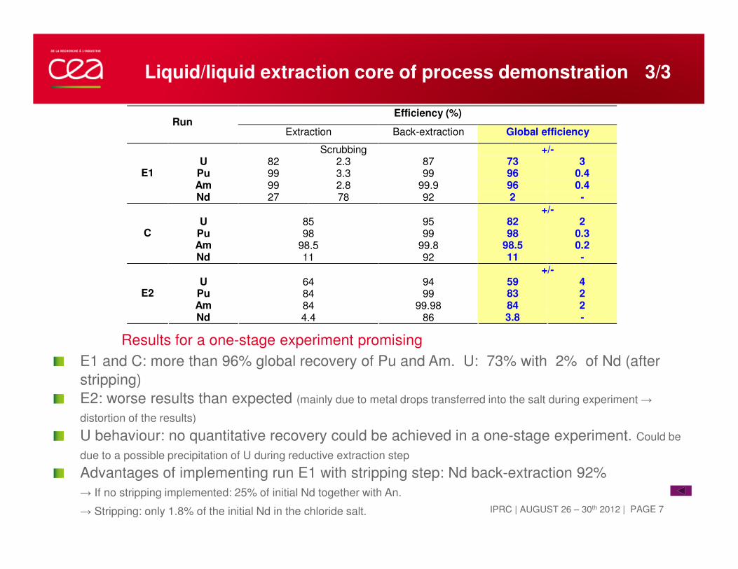
Results for a one-stage experiment promising
E1 and C: more than 96% global recovery of Pu and Am. U: 73% with 2% of Nd (after
stripping)
E2: worse results than expected (mainly due to metal drops transferred into the salt during experiment →
distortion of the results)
U behaviour: no quantitative recovery could be achieved in a one-stage experiment. Could be
due to a possible precipitation of U during reductive extraction step
Advantages of implementing run E1 with stripping step: Nd back-extraction 92%
→ If no stripping implemented: 25% of initial Nd together with An.
→ Stripping: only 1.8% of the initial Nd in the chloride salt. | PAGE 7IPRC | AUGUST 26 – 30th 2012
Efficiency (%) Run
Extraction Back-extraction Global efficiency
Scrubbing +/- U 82 2.3 87 73 3
Pu 99 3.3 99 96 0.4 Am 99 2.8 99.9 96 0.4
E1
Nd 27 78 92 2 - +/-
U 85 95 82 2 Pu 98 99 98 0.3 Am 98.5 99.8 98.5 0.2
C
Nd 11 92 11 -
+/- U 64 94 59 4
Pu 84 99 83 2 Am 84 99.98 84 2
E2
Nd 4.4 86 3.8 -
Liquid/liquid extraction core of process demonstration 3/3

Conversion to oxide step
17 OCTOBRE 2012
| PAGE 8
CEA | 10 AVRIL 2012

Conversion into oxides 1/5
After Back-extraction step:
An(III) in molten chlorides must be converted into
oxide form.
For nuclear fuel re-fabrication:
Quantitative
Oxide form AnO2
Solid solution (U,Pu,MA)O2
Reference routes: precipitation with carbonates
Li2CO3 � 2Li+ + CO2(g) +O2-
Leads to increase of salt volume
Chosen route: precipitation using a process
gas
⇒ Wet Argon sparging
Studied systems:
Nd – Ce (inactive study) and U – Pu
17 OCTOBRE 2012 | PAGE 9
Conversion in molten salt
An3+
O2-
LiCl-CaCl2(700°C)
Ar + H2O
Ar + HCl
O2-
H2O(g) → O2-(salt) + 2HCl(g)
DEN/DRCP/SCPS/LEPS IPRC | AUGUST 26 – 30th 2012

IPRC | AUGUST 26 – 30th 2012
Conversion into oxides 2/5
17 OCTOBRE 2012 | PAGE 10
Ar+H2O
LiCl-CaCl2700°C
Ar+HCl
Uranium
Plutonium
LiCl-CaCl2
Precipitate
25 35 45 55 65 75
Inte
nsi
té (
u.a
.)
2θ (°)
UO2
Au Au Au
UCl3(salt) + 2H2O(g) → UO2(ppt) + 3HCl(g) + ½H2
a=5.470(1)
XRD
SEM

Conversion into oxides 3/5
Conversion of Nd(III) – Ce(III)
XNd = Nd/Ce+Nd → 0; 0.25; 0.5; 0.75 and 1
17 OCTOBRE 2012 | PAGE 11
NdCl3(salt) + H2O(g) → NdOCl(ppt) + 2HCl(g)
40 42 44 46 48 50 52 54 56 58 60 62 64
Inte
nsi
té (
u.a
.)
2θ (°)
NdOCl
xNd=1
Inte
nsit
y(a
. u
.)
DEN/DRCP/SCPS/LEPS IPRC | AUGUST 26 – 30th 2012

Conversion into oxides 3/5
Conversion of Nd(III) – Ce(III)
XNd = Nd/Ce+Nd → 0; 0.25; 0.5; 0.75 and 1
17 OCTOBRE 2012 | PAGE 12
40 42 44 46 48 50 52 54 56 58 60 62 64
Inte
nsi
té (
u.a
.)
2θ (°)
CeO2
xNd=1
CeOCl
xNd=0
xNd=0.25
xNd=0.50
xNd=0.75
Ce1-xNdxO2-0.5X
CeCl3(salt) + H2O(g) → CeOCl(ppt) + 2HCl(g)
CeCl3(salt) + 2H2O(g) → CeO2(ppt) + 3HCl(g) + ½H2
80%
20%
Ce1-yNdyOCl
Inte
nsit
y(a
. u
.)
ICP analysis : 99.9%conversion rate
Nd-Ce Solid solution formation
DEN/DRCP/SCPS/LEPS IPRC | AUGUST 26 – 30th 2012

DEN/DRCP/SCPS/LEPS IPRC | AUGUST 26 – 30th 2012
Conversion of U(III) – Pu(III)
XPu = Pu/U+Pu → 0; 0.25; 0.5; 0.75 and 1
Uranium volatilization observed (10-15%)
ICP analysis : conversion rate >99.9%
Conversion into oxides 4/5
17 OCTOBRE 2012 | PAGE 13
PuO2
xPu=0.20
xPu=0.50
xPu=0.75
25 30 35 40 45 50
Inte
nsi
té (
u.a
.)
2θ (°)
UO2
xPu=0standard
Inte
nsit
y(a
. u
.)
U3+ U4+ UO2e-
2O2-
Pu3+ Pu4+ PuO2e-
2O2-
E(V) Intermediate sample
XPu U3+ Pu3+
0.75 < 1% 70%
0.5 < 1% 76%
0.2 < 1% 61%
xPu=1
PuOCl

17 OCTOBRE 2012 | PAGE 14
Conversion into oxides 5/5
Nd(III)-Ce(III) precipitation :
Partially oxidative method
1 - Quantitative
2 - Oxide Form LnO2
3 - Solid solution
OK
OK calcination
OK
U(III)-Pu(III) precipitation
1 - Quantitative
2 - Oxide Form AnO2
3 - Solid solution
OK
OK
OK
DEN/DRCP/SCPS/LEPS IPRC | AUGUST 26 – 30th 2012
Hydrofluorination : in situ HF
production
17 OCTOBRE 2012
| PAGE 15
CEA | 10 AVRIL 2012

Hydrofluorination by in situ produced HF 1/3
17 OCTOBRE 2012 | PAGE 16
Zone 1 zone2 zone3
HKF2 FP2O3 KF
Safety bottle
2 KOH trap
Oven
Air inlet
Antiacid filter Antiacid filter
Ventilation
Water
cooling
Zone 1 zone2 zone3
HKF2 FP2O3 KF
Safety bottle
2 KOH trap
Oven
Air inlet
Antiacid filter Antiacid filter
Ventilation
Water
cooling
Why in-situ production of HF?
Conversion of spent fuel into fluoride is needed.
Few hot cells facilities are equipped with HF gas line
HF produced by dissociation of solid HF-KF at 200-350°C
Experimental set-up including three eating areas
Study of oxide fluorination: La, Ce, Pr, Nd, Mo, Ru, Rh, Sm, Eu, Pr, Zr, Sr, Ag, Y
Determination of the best reaction conditions
Assessing behaviour of oxides under HF gas flow (fluorination rate, final product)
200-350°C
HF generation
300-500°C
Oxide fluorination
100°C
Excess HF trapped
DEN/DRCP/SCPS/LEPS IPRC | AUGUST 26 – 30th 2012

GIBBS free energy of hydrofluorination reaction normalized to 1 HF mole
-200,0
-150,0
-100,0
-50,0
0,0
50,0
100,0
0 100 200 300 400 500 600 700 800 900 1000
Te mpe r a t ur e °C
Nd2O3
Pr2O3
Rh2O3
Eu2O3
Y2O3
La2O3
Sm2O3
MoO3
RuO2
ZrO2
CeO2
SrO
AgO
lant hanides
Plat inoides
ZrO2
∆∆ ∆∆G
(K
J/m
ol H
F)
Temperature °C
Hydrofluorination by in situ produced HF 2/3
Thermodynamic cacluations (HSC Chemistry® V.4.1)
Gibbs free energy of fluoride formation from oxide form, with HF → Determination of
optimum experimental temperature range.
Temperature acts in opposite direction
However, Gas/Solid reaction → higher specific surface of the solid and higher temperature should favour kinetic
Ln oxides: temperatures ranging from 400 to 500°C are favourable.
ZrO2: favourable temperature rather from 300 to 320°C.| PAGE 17IPRC | AUGUST 26 – 30th 2012

Hydrofluorination by in situ produced HF 3/3
17 OCTOBRE 2012 | PAGE 18
Overview of the set-up Ar inlet + HF production area
Water cooling system
Opening the reactor
Oxide → Fluoride conversion basket
Hydrofluorination reactor
Experimental results
Flurorination experiments: 6h, 330°C to 420°C
(depending on oxide to convert), HF excess ~3.5
Oxides behaviour: (determined by XRD)
Nd2O3, CeO2, SrO, Eu2O3, La2O3,Y2O3, Sm2O3,
Pr2O3 successfully converted into fluorides
→ Pr, La, Eu presence of oxyfluorides could be evidenced
MoO3, Rh2O3, RuO2, AgO remained in oxide form
good agreement with thermodynamic calculations.
Case of ZrO2: Several experiments on
commercial and nanopowder ZrO2.
Commercial ZrO2 → No fluorination
Nanopowder (350°C) → 25% of Zr fluorinated
DEN/DRCP/SCPS/LEPS IPRC | AUGUST 26 – 30th 2012

17 OCTOBRE 2012 | PAGE 19
Potential
routes
Principle Media Average working Temp.
Predilection fuels
Remarks
Electrorefining/
Electrolysis
Electrorefining
Selective electrodeposition
LiCl,
LiCl-KCl
450°C Metal, (oxide) The most studied and the most advanced pyro process
At pilot scale
Electrolysis Selective electrodeposition
NaCl-2CsCl
(with
Cl2(g)/O2(g))
550-800°C Oxide At semi-pilot scale, coupled with
vibrocompact fuel fabrication
Reductive
extraction
Selective extraction in a metal phase (Cd) with reductor (Li)
LiCl-KCl/Cd
450°C Oxide, Metal Laboratory scale
Reductive
extraction
Selective extraction in a metal phase (Al)
LiF-AlF3/Al
830°C Oxide Carbide
Laboratory scale, high temp. and corrosive solvents and gases ����material issues
Very good recovery yields and separation factors
DEN/DRCP/SCPS/LEPS IPRC | AUGUST 26 – 30th 2012

DEN/DRCP/SCPS/LEPS IPRC | AUGUST 26 – 30th 2012
Conclusion
The core of process is now well assessed at lab scale with encouraging results on a
One stage Extraction-Back-extraction experiment
Conversion step:
Use of wet Argon → promising method. U(III) and Pu(III) coconversion lead to UO2 and PuO2 mixture
Still some further investigations are needed
Hydrofluorination highlighted Zr behaviour (should be studied and simulated in the whole process)
Analytical techniques are under development.
17 OCTOBRE 2012 | PAGE 20
PerspectivesReference Route in molten fluorides
A few steps need to be tested with genuine fuel (thermal treatment,
digestion)
An alternative head of process is under investigation in order to
prevent use of HF to convert oxides fuels into fluorides.
Electrorefining process in molten chloride
CEA is collaborating with JRC-ITU and LGC (Toulouse university,
France) to study the salt cleaning step by exhaustive electrolysis.
Development of a dedicated reactor within the framework of the ACSEPT program.

DEN
DRCP
SCPS
LEPS
Commissariat à l’énergie atomique et aux énergies alternatives
Centre de Marcoule | 30207 Bagnols sur Cèze
T. +33 (0)4 66 79 63 11 | F. +33 (0)4 66 79 65 67
Etablissement public à caractère industriel et commercial | RCS Paris B 775 685 01917 OCTOBRE 2012
| PAGE 21
CEA | 10 AVRIL 2012
Thank you for your attention


![Classroom Embedded Assessment [CEA] Title: Particle Modellouisville.edu/education/centers/crimsted/cea-examples/grades-3-5-cea... · This CEA is administered at the beginning of a](https://static.fdocuments.in/doc/165x107/5e0c9c02fc643312e40fb808/classroom-embedded-assessment-cea-title-particle-this-cea-is-administered-at.jpg)


