Development ofTubular Proton Conducting Electrolysers · Development ofTubular Proton Conducting...
22
Development ofTubular Proton Conducting Electrolysers Einar Vøllestad 2 , M.L. Fontaine 1 , C. Denonville 1 , R. Strandbakke 2 , J.M. Serra 3 , D.R. Beeaff 4 , C. Vigen 4 and T. Norby 2 1 SINTEF Materials and Chemistry, 2 University of Oslo, 3 CSIC, 4 CoorsTek Membrane Sciences AS
-
Upload
nguyenthien -
Category
Documents
-
view
224 -
download
1
Transcript of Development ofTubular Proton Conducting Electrolysers · Development ofTubular Proton Conducting...

Development of Tubular Proton Conducting Electrolysers
Einar Vøllestad2, M.L. Fontaine1, C. Denonville1, R. Strandbakke2, J.M. Serra3, D.R. Beeaff4, C. Vigen4 and T. Norby2
1 SINTEF Materials and Chemistry, 2 University of Oslo, 3 CSIC, 4 CoorsTek Membrane Sciences AS

Development of Tubular Proton Conducting Electrolysers
Einar Vøllestad2, M.L. Fontaine1, C. Denonville1, R. Strandbakke2, J.M. Serra3, D.R. Beeaff4, C. Vigen4 and T. Norby2
1 SINTEF Materials and Chemistry, 2 University of Oslo, 3 CSIC, 4 CoorsTek Membrane Sciences AS
Why high temperature proton ceramic electrolysers?
Processing and performance of early-stage single cells
Up-scaling strategies for tubular proton ceramic electrolysers

High temperature electrolysis enables utilization of waste heat resources
PCE SOE
2H2OΔH
2H2 + O2

Key differences between SOE and PCE- advantages and challenges
Solid Oxide Electrolysers Well proven technology
Scalable production High current densities at thermo-neutral voltage
Long term stability challenges Delamination of O2-electrode Oxidation and degradation of Ni-electrode with high
steam contents High temperatures
Proton Ceramic Electrolysers Less mature technology
Fabrication and processing challenges Produces dry H2 directly Potentially intermediate temperatures
Slow O2-electrode kinetics
U
2O2-
2H2O
2H2
O2
SOEC
600-800°C
4e-
U
4H+2H2
O2
2H2OPCEC
400-700°C
4e-

Development of tubular cathode supported
electrolyte cell
Development and optimization of anodes and current collection
Single tube module development and
testing
Multi-tube module testingAim: 1kW demo
H+
H+
H+
O2H2O
e-
e-
BZY
O2e-
O2
H+
H+
H+
H2O
e-
e-
BZY
O2
e-
H+
H+
H+
O2H2O
e-
e-
BZY
O2e-
O2-
Protonic conductor e- Conductor nanoparticlesMixed Oxygen ion-electronic conductor
a b c
Process integration and evaluation
High temperature electrolyser with novel proton ceramic tubular modules (2014-2017)
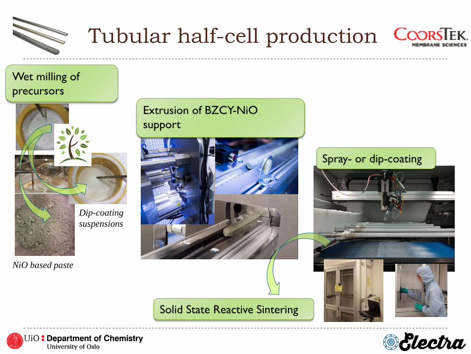
Tubular half-cell production
Dip-coatingsuspensions
NiO based paste
Wet milling of precursors
Solid State Reactive Sintering
Extrusion of BZCY-NiOsupport
Spray- or dip-coating

BZCY72 // BZCY72-NiO BZY10 // BZY10-NiO BZY10 // BZCY72-NiO
Dense electrolyte @ 1550°C – 24h1610°C – 6h
Porous electrolyte @ 1550°C – 24h1610°C – 6h1650°C – 6h1670°C – 6h
Dense electrolyte @ 1550°C – 24 h1610°C – 6 h
100 microns 100 microns 100 microns
40 microns 40 microns 40 microns
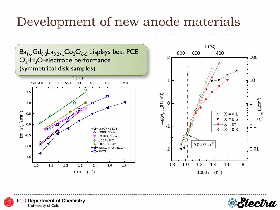
Development of new anode materials
1.0 1.1 1.2 1.3 1.4 1.5 1.6
-1.5
-1.0
-0.5
0.0
0.5
1.0
1.5
GBCF / BZCY BSCF / BCY Pr2NiO4 / BCY LSCF / BCY BGCF / BCY BGLC (x=0) / BZCY BCZF
log
((Rp (Ω
cm2 )
1000/T (K-1)
750 700 650 600 550 500 450 400 350T (°C)
Ba1-xGd0.8La0.2+xCo2O6-δ displays best PCE O2-H2O-electrode performance(symmetrical disk samples)
0.8 1.0 1.2 1.4 1.6 1.8
-2
-1
0
1
2
X = 0.1 X = 0.5 X = 0* X = 0.3
Log(
Rp,
app(Ω
cm2 ))
1000 / T (K-1)
800 600 400
0.01
0.1
1
10
100
Rp,
app(Ω
cm2 )
T (°C)
0.04 Ωcm2

Anode processing on tubular cells
Electrolysis tests using gold as the current collector
Fired in dual atmosphere with applied bias:- 2% O2 outside, 5% H2 inside- Ecell = 1.4 V during firing (above 500°C)
Steam electrode (BGLC785) drip-coated and brush-painted
Capped and sealed using custom-made glass ceramic (CoorsTek Membrane Sciencies)
Single segment, reduced at 1000°C for 24h in 5% H2

Electrolysis tests of single cell
0 50 100 150 200 250
1.0
1.5
2.0
600°C550°C
650°C700°C
Pot
entia
l (V
)
Current (mA cm-2)
pO2: 80 mbar pH2O: 1.5 barpH2: 300 mbar

Improved performance with increasing steam content and current load
4 5 6 7 8
3
2
1
0
-1
OCV 11 mA cm-2
21 mA cm-2
64 mA cm-2
Z// (Ωcm
2 )
Z/ (Ωcm2)
Both electrolyte and electrode performance improved with increased steam content
0.00 0.05 0.10 0.15 0.20 0.250.8
1.0
1.2
1.4
1.6
1.8
pH2O: 1.5 bar
pH2O: 0.5 bar
Vol
tage
(V)
Current density (mA cm-2)
High ohmic resistance indicates current collection limitations
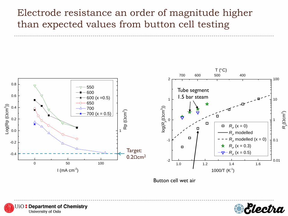
Electrode resistance an order of magnitude higher than expected values from button cell testing
0 50 100
-0.4
-0.2
0.0
0.2
0.4
0.6
0.8
Rp
(Ωcm
2 )
Log(
Rp
(Ωcm
2 ))
I (mA cm-2)
550 600 600 (x =0.5) 650 700 700 (x = 0.5)
1
Target: 0.2Ωcm2
1.0 1.2 1.4 1.6-2
-1
0
1
2
1000/T (K-1)
log(
Rp(Ω
cm2 ))
RP (x = 0) RP modelled RP modelled (x = 0) RP (x = 0.3) RP (x = 0.5)
700 600 500 400
0.01
0.1
1
10
100
Rp(Ω
cm2 )
T (°C)
Tube segment 1.5 bar steam
Button cell wet air

Scaling up – segmented tubes to drive up the voltage

Scaling up – stacking individual segments

Scaling up – “Printing in series”
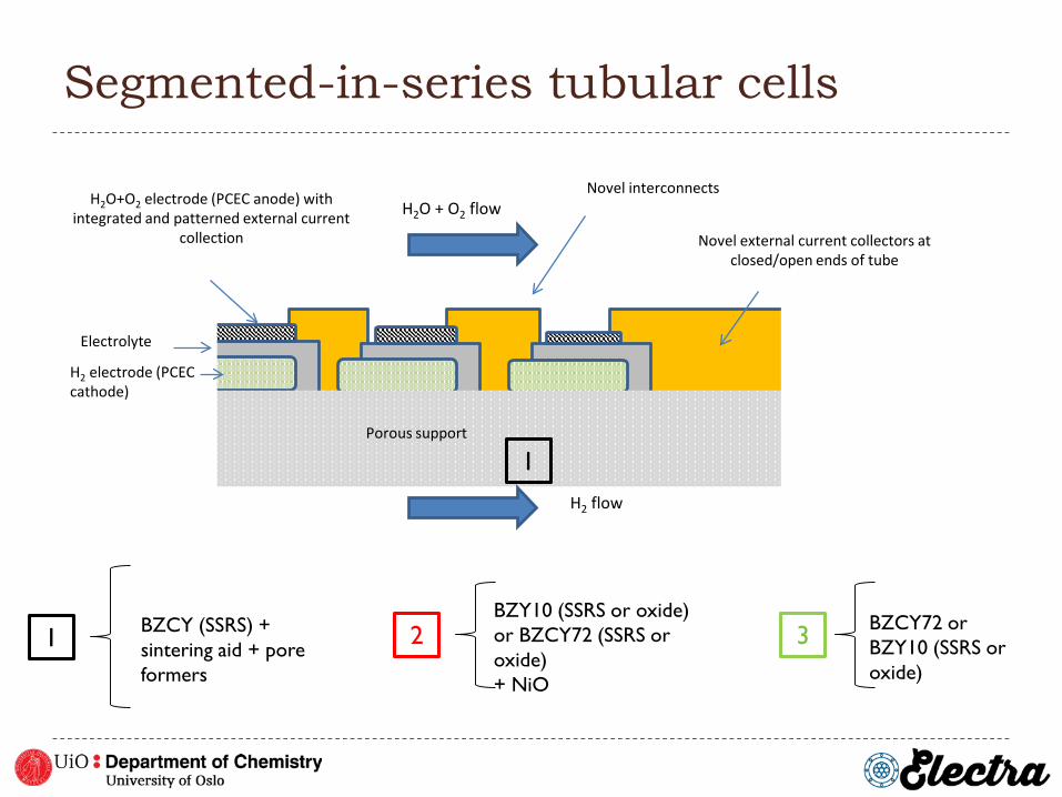
Segmented-in-series tubular cells
Porous support
H2 electrode (PCEC cathode)
H2O+O2 electrode (PCEC anode) with integrated and patterned external current
collection
Novel interconnectsH2O + O2 flow
H2 flow
Electrolyte
Novel external current collectors at closed/open ends of tube
1
1 BZCY (SSRS) + sintering aid + pore formers
2BZY10 (SSRS or oxide)or BZCY72 (SSRS or oxide)+ NiO
3 BZCY72 or BZY10 (SSRS or oxide)

Manufacturing process
Powder conditioning
Pastes preparation
Production of tubes by extrusion and collars
Dip-coating of tubes
Slurries preparation
Annealing of tubes (hang-firing)
• Milling of SSRS precursors and oxide powders
• Drying• Sieving• Batching
• Water based slurryfor SSRS mixtures
• Organic basedslurries for oxidemixtures
• Drying• Cutting• Masking and coating
• Drying in air (organicbased coating) or at 60°C for water basedsuspensions
Green supports with electrodes
Green support coated with cathode (green) and electrolyte (white) layers
Hang-firing of cells
Clean room activities
3 cm
20 cm

Parameters investigated
SupportsSupport +
fuel electrode
Support + fuel electrode +
electrolyte
Shrinkage; porosity• Annealing• PF content• Sintering aid
Shrinkage, porosity• Coated part • Uncoated part
Thickness of electrode• Viscosity• Powder loading
Shrinkage, porosity• Coated part• Uncoated part
Thickness of electrode• Viscosity• Powder loading
Thickness and densification of electrolyte• Oxide vs SSRS• Powder loading
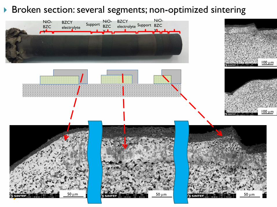
NiO-BZCY
BZCY electrolyte
NiO-BZCY
BZCY electrolyte
NiO-BZCY
Support Support
100 µm
100 µm
50 µm50 µm50 µm
Broken section: several segments; non-optimized sintering
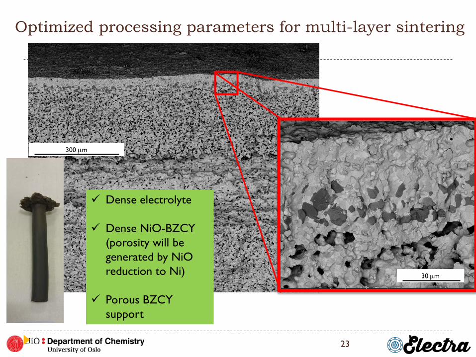
Optimized processing parameters for multi-layer sintering
23
30 µm
300 µm
Dense electrolyte
Dense NiO-BZCY (porosity will be generated by NiOreduction to Ni)
Porous BZCY support

Conclusions High temperature proton ceramic electrolysers can produce dry,
pressurized hydrogen
Processing and manufacturing of tubular half cells is now well established
State-of-the-art electrolyser anodes are developed on button cell scale Deposition and firing protocols for tubular cells currently being developed
Segmented-in-series tubular cells are needed to reduce total current of tubes in real operational conditions
Acknowledgements
The research leading to these results has received funding from the European Union's Seventh Framework Programme (FP7/2007-2013) for the Fuel Cells and Hydrogen Joint Technology Initiative under grant agreement n° 621244.
Thank you for your
attention!