An Intermediate Temperature Metal-Supported Proton ... · An Intermediate Temperature...
22
An Intermediate Temperature Metal-Supported Proton-Conducting Solid Oxide Fuel Cell Stack 18 th Annual SOFC Workshop June 14, 2017
Transcript of An Intermediate Temperature Metal-Supported Proton ... · An Intermediate Temperature...
An Intermediate Temperature
Metal-Supported Proton-Conducting
Solid Oxide Fuel Cell Stack
18th Annual SOFC Workshop
June 14, 2017
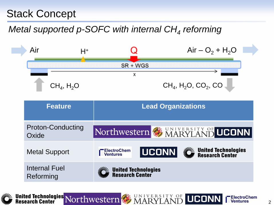
Stack Concept
2
Feature Lead Organizations
Proton-Conducting
Oxide
Metal Support
Internal Fuel
Reforming
CH4, H2O CH4, H2O, CO2, CO
Air Air – O2 + H2O
Metal supported p-SOFC with internal CH4 reforming
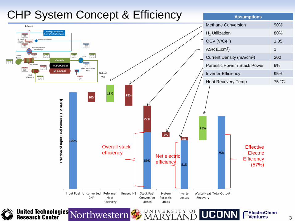
CHP System Concept & Efficiency
3
Assumptions
Methane Conversion 90%
H2 Utilization 80%
OCV (V/Cell) 1.05
ASR (cm2) 1
Current Density (mA/cm2) 200
Parasitic Power / Stack Power 9%
Inverter Efficiency 95%
Heat Recovery Temp 75 °C
Overall stack
efficiency Net electric
efficiency
Effective
Electric
Efficiency
(57%)
12.8 g/s
35 C
13.4 g/s 0.6 g/s
80 C 35 C
13.4 g/s 12.6 g/s 12.7 g/s 12.7 g/s
246 C 463 C 538 C 385 C
12.6 g/s
15 C
0.6 g/s
463 C
0.7 g/s
13.4 g/s 463 C
598 C
12.7 g/s 0.2 g/s
385 C 15 C
HEX Hot In
Burn In Cath
Cath ExitCath In Boil Out
Anode Out
HEX Hot Out
NG In
Rec. H2O
Steam
HR Exit
Exhaust
Air Inflow Cathode
SR & Anode
PC SOFC Stack
Stack Afterburner
Exhaust Heat RecoveryHeat Exchanger
Fresh Fuel & SteamMixer
Building/Potable Water Heating/Cooling Sub-System
Natural Gas
Exhaust
SystemBlower
Recuperator
Air CooledExhaust
Condenser
Boiler
Recovered Water Pump
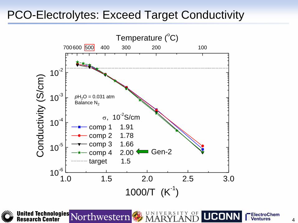
PCO-Electrolytes: Exceed Target Conductivity
4
1.0 1.5 2.0 2.5 3.010
-6
10-5
10-4
10-3
10-2
1000/T (K-1)
Co
nd
uctivity (
S/c
m)
comp 1 1.91
comp 2 1.78
comp 3 1.66
comp 4 2.00
target 1.5
, 10-2S/cm
700600 500 400 300 200 100
Temperature (oC)
pH2O = 0.031 atm
Balance N2
Gen-2
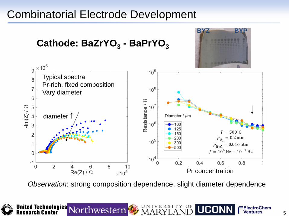
Combinatorial Electrode Development
5
Pr concentration
Cathode: BaZrYO3 - BaPrYO3
Typical spectra
Pr-rich, fixed composition
Vary diameter
Observation: strong composition dependence, slight diameter dependence
diameter
BYZ BYP
0 1 2 3 40.0
0.2
0.4
0.6
0.8
1.0
1.2
700 C
650 C
600 C
550 C
500 C
Current Density (A cm-2)
Volta
ge
(V
)
0.0
0.2
0.4
0.6
0.8
1.0
1.2
Po
we
r De
nsity
(w c
m-2)
0 1 2 3 40.0
0.2
0.4
0.6
0.8
1.0
1.2
700 C
650 C
600 C
550 C
500 C
Current Density (A cm-2)
Volta
ge
(V
)
0.0
0.2
0.4
0.6
0.8
1.0
1.2
Po
we
r De
nsity
(w c
m-2)
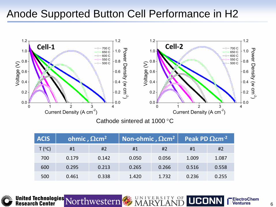
Anode Supported Button Cell Performance in H2
6
Cell-1 Cell-2
ACIS ohmic , cm2 Non-ohmic , cm2 Peak PD cm-2
T (oC) #1 #2 #1 #2 #1 #2
700 0.179 0.142 0.050 0.056 1.009 1.087
600 0.295 0.213 0.265 0.266 0.516 0.558
500 0.461 0.338 1.420 1.732 0.236 0.255
Cathode sintered at 1000 C
0 100 200 300 400 500 600 7000.0
0.2
0.4
0.6
0.8
1.0
Curr
ent
Density (
A c
m-2
)
Time (h)
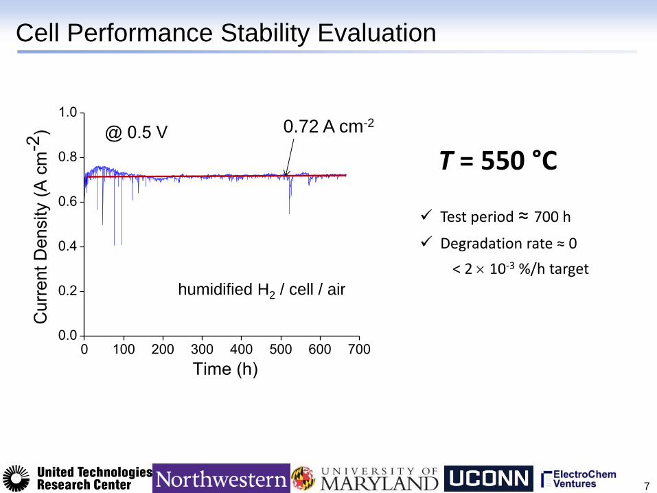
@ 0.5 V
Cell Performance Stability Evaluation
7
humidified H2 / cell / air
T = 550 °C
Test period ≈ 700 h
Degradation rate ≈ 0
< 2 10-3 %/h target
0.72 A cm-2
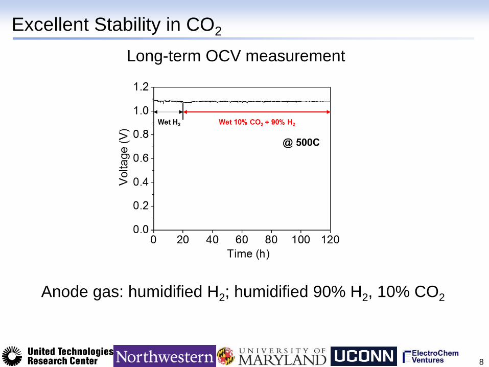
Excellent Stability in CO2
8
Long-term OCV measurement
Anode gas: humidified H2; humidified 90% H2, 10% CO2
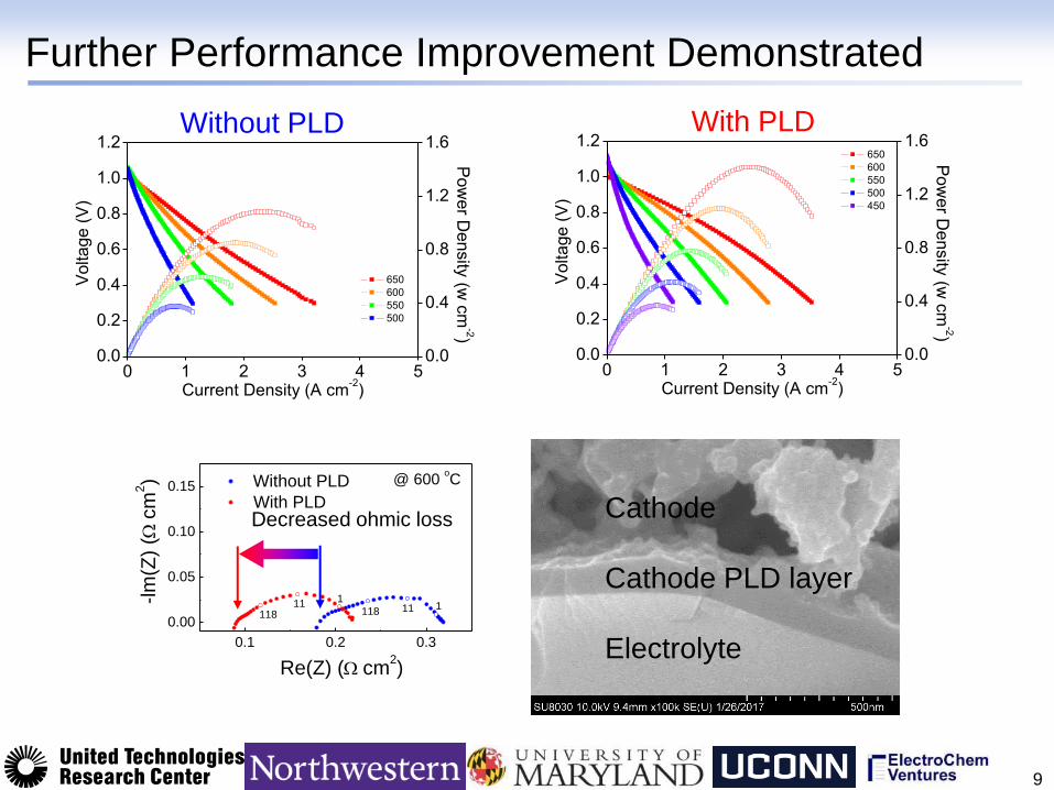
Further Performance Improvement Demonstrated
9
0 1 2 3 4 50.0
0.2
0.4
0.6
0.8
1.0
1.2 650
600
550
500
450
Current Density (A cm-2)
Volta
ge
(V
)
0.0
0.4
0.8
1.2
1.6
Pow
er D
ensity
(w c
m-2)
0 1 2 3 4 50.0
0.2
0.4
0.6
0.8
1.0
1.2
650
600
550
500
Current Density (A cm-2)
Voltage (
V)
0.0
0.4
0.8
1.2
1.6
Po
we
r De
nsity
(w c
m-2)
0.1 0.2 0.3
0.00
0.05
0.10
0.15
111118
Without PLD
With PLD
-lm
(Z)
(c
m2)
Re(Z) (cm2)
@ 600 oC
11811 1
Decreased ohmic loss
Without PLD With PLD
Cathode
Cathode PLD layer
Electrolyte
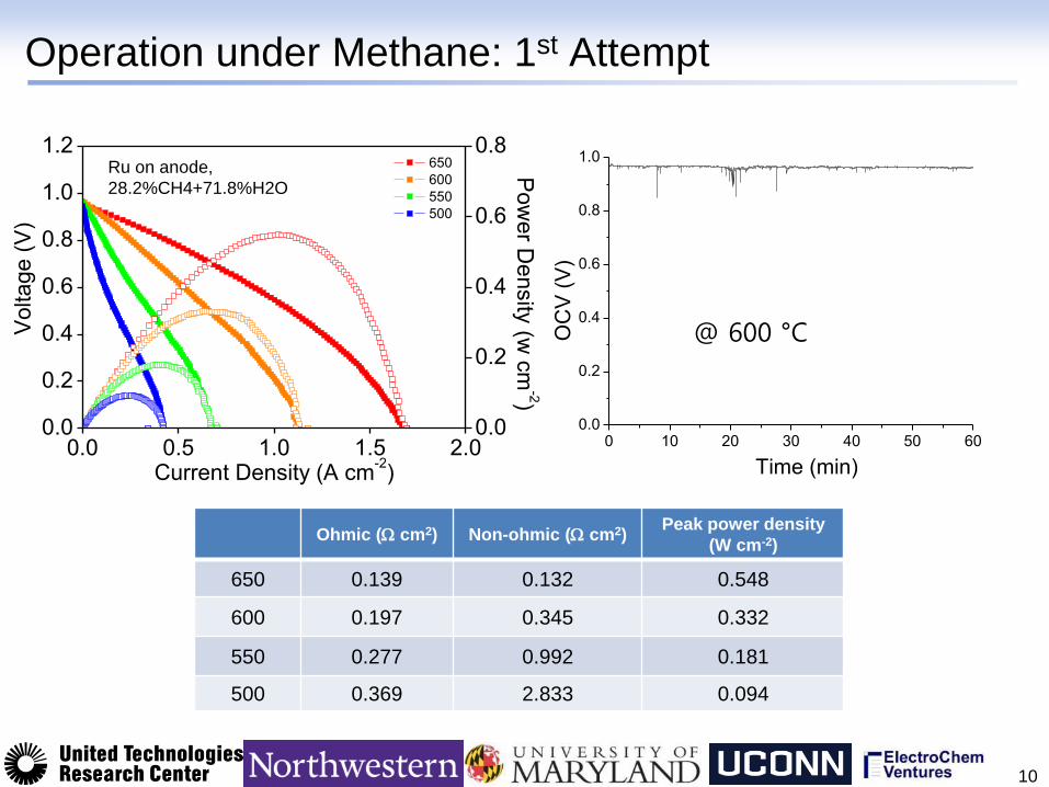
Operation under Methane: 1st Attempt
10
Ohmic ( cm2) Non-ohmic ( cm2) Peak power density
(W cm-2)
650 0.139 0.132 0.548
600 0.197 0.345 0.332
550 0.277 0.992 0.181
500 0.369 2.833 0.094
0.0 0.5 1.0 1.5 2.00.0
0.2
0.4
0.6
0.8
1.0
1.2 650
600
550
500
Current Density (A cm-2)
Volta
ge
(V
)
0.0
0.2
0.4
0.6
0.8
P
ow
er D
ensity
(w c
m-2)
Ru on anode,
28.2%CH4+71.8%H2O
0 10 20 30 40 50 600.0
0.2
0.4
0.6
0.8
1.0
OC
V (
V)
Time (min)
@ 600 °C
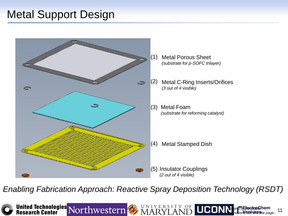
Metal Support Design
11
Metal Porous Sheet (substrate for p-SOFC trilayer)
Metal C-Ring Inserts/Orifices (3 out of 4 visible)
Metal Foam (substrate for reforming catalyst)
Metal Stamped Dish
Insulator Couplings (2 out of 4 visible)
(1)
(2)
(3)
(4)
(5)
Subject to the export
restrictions on the title page..
Enabling Fabrication Approach: Reactive Spray Deposition Technology (RSDT)
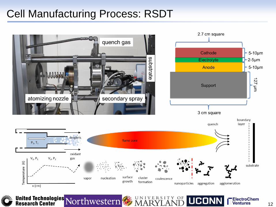
Cell Manufacturing Process: RSDT
12
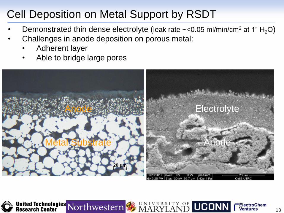
Cell Deposition on Metal Support by RSDT
13
• Demonstrated thin dense electrolyte (leak rate ~<0.05 ml/min/cm2 at 1” H2O)
• Challenges in anode deposition on porous metal:
• Adherent layer
• Able to bridge large pores
Electrolyte
Anode Metal Substrate
Anode
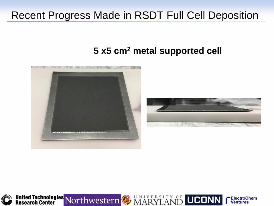
Recent Progress Made in RSDT Full Cell Deposition
5 x5 cm2 metal supported cell
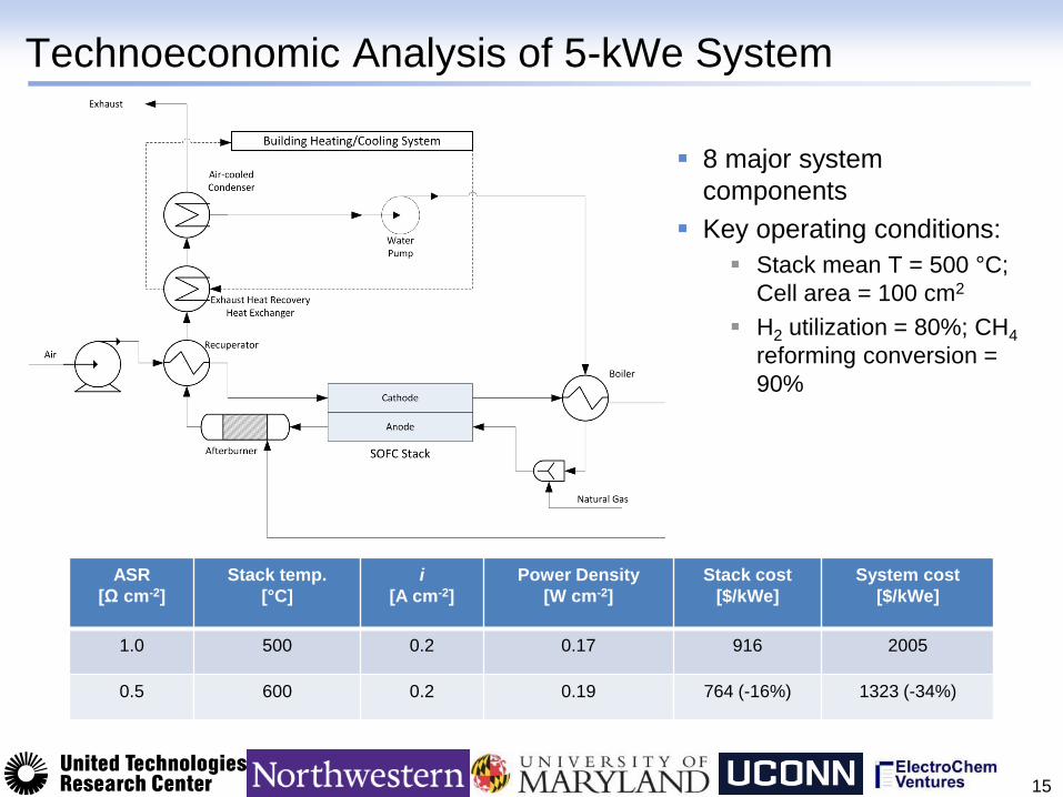
Technoeconomic Analysis of 5-kWe System
15
8 major system
components
Key operating conditions:
Stack mean T = 500 °C;
Cell area = 100 cm2
H2 utilization = 80%; CH4
reforming conversion =
90%
ASR
[Ω cm-2]
Stack temp.
[°C]
i
[A cm-2]
Power Density
[W cm-2]
Stack cost
[$/kWe]
System cost
[$/kWe]
1.0 500 0.2 0.17 916 2005
0.5 600 0.2 0.19 764 (-16%) 1323 (-34%)
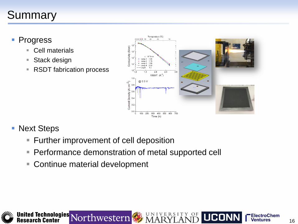
Summary
Progress
Cell materials
Stack design
RSDT fabrication process
Next Steps
Further improvement of cell deposition
Performance demonstration of metal supported cell
Continue material development
16
Acknowledgements
17
Organization Team Members
Sossina Haile, Sihyuk Choi, Chris
Kucharczyk, Daekwang Lim
John Yamanis
Radenka Maric, Tim Myles, Ryan Ouimet
Ichiro Takeuchi, Xiaohang Zhang, Yangang
Liang
Tianli Zhu, Justin Hawkes, Sean Emerson,
Neal Magdefrau, Xian Tang
Grigorii Soloveichik, Scott Litzelman, John Tuttle,
John Lemmon
The information, data, or work presented herein was funded in part by the Advanced Research Projects
Agency-Energy (ARPA-E), U.S. Department of Energy, under Award Number DE-AR0000498.

Back Up
18
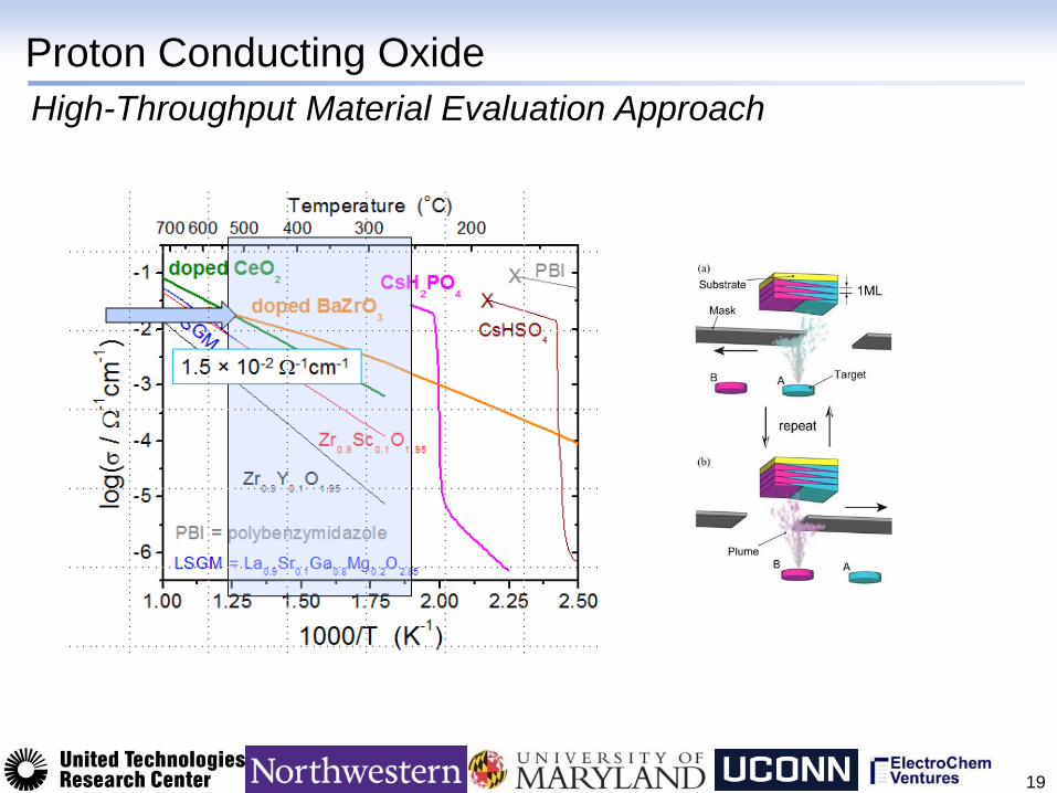
Proton Conducting Oxide
19
High-Throughput Material Evaluation Approach
20 25 30 35 40
Inte
nsity (
a.
u.)
2 Theta
20 40 60 80
after 100% CO2 500
oC/12h
Inte
nsity (
a.
u.)
2 Theta
as-sintered
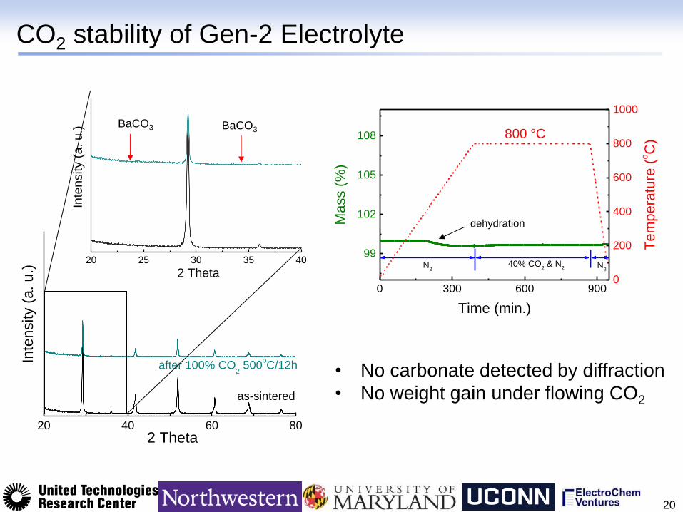
CO2 stability of Gen-2 Electrolyte
20
BaCO3 BaCO3
0 300 600 900
99
102
105
108
N2
40% CO2 & N
2
Mass (
%)
Time (min.)
N2
0
200
400
600
800
1000
Tem
pera
ture
(oC
)
• No carbonate detected by diffraction
• No weight gain under flowing CO2
800 °C
dehydration
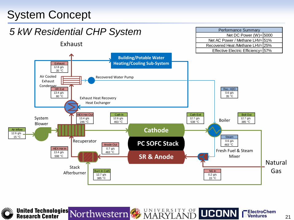
System Concept
21
12.8 g/s
35 C
13.4 g/s 0.6 g/s
80 C 35 C
13.4 g/s 12.6 g/s 12.7 g/s 12.7 g/s
246 C 463 C 538 C 385 C
12.6 g/s
15 C
0.6 g/s
463 C
0.7 g/s
13.4 g/s 463 C
598 C
12.7 g/s 0.2 g/s
385 C 15 C
HEX Hot In
Burn In Cath
Cath ExitCath In Boil Out
Anode Out
HEX Hot Out
NG In
Rec. H2O
Steam
HR Exit
Exhaust
Air Inflow Cathode
SR & Anode
PC SOFC Stack
Stack Afterburner
Exhaust Heat RecoveryHeat Exchanger
Fresh Fuel & SteamMixer
Building/Potable Water Heating/Cooling Sub-System
Natural Gas
Exhaust
SystemBlower
Recuperator
Air CooledExhaust
Condenser
Boiler
Recovered Water Pump
Net DC Power (W)= 5000
Net AC Power / Methane LHV= 51%
Recovered Heat /Methane LHV= 25%
Effective Electric Efficiency= 57%
Performance Summary5 kW Residential CHP System
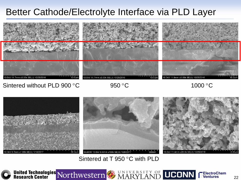
Better Cathode/Electrolyte Interface via PLD Layer
22
(a) (b) (c)
950 C Sintered without PLD 900 C 1000 C
Sintered at T 950 C with PLD