Development of Vortex Filament Method for Wind Power ... · PDF fileProf. Spyros Voutsinas**,...
28
DEVELOPMENT OF VORTEX F ILAMENT METHOD FOR WIND P OWER AERODYNAMICS PhD Candidate Hamidreza Abedi * , [email protected] Supervisors Prof. Lars Davidson * , [email protected] Prof. Spyros Voutsinas ** , [email protected] * Division of Fluid Dynamics, Department of Applied Mechanics, Chalmers University of Technology, G¨ oteborg Sweden ** Fluid Section, School of Mechanical Engineering, National Technical University of Athens, Athens, Greece
Transcript of Development of Vortex Filament Method for Wind Power ... · PDF fileProf. Spyros Voutsinas**,...
DEVELOPMENT OF VORTEX FILAMENT METHOD
FOR WIND POWER AERODYNAMICS
PhD Candidate
Hamidreza Abedi*, [email protected]
Supervisors
Prof. Lars Davidson*, [email protected]
Prof. Spyros Voutsinas**, [email protected]*Division of Fluid Dynamics, Department of Applied Mechanics, Chalmers
University of Technology, Goteborg Sweden**Fluid Section, School of Mechanical Engineering, National Technical
University of Athens, Athens, Greece
OUTLINE
1 Motivation
2 Difficulty
3 Goal
4 Theory & modeling
5 Aerodynamic load calculation
Results
6 Wake aerodynamics
Results
7 Turbulent & sheared inflow
Results
8 Conclusion & future work
9 Acknowledgments
PhD Disputation, Hamidreza Abedi 15-April-2016 2 / 28
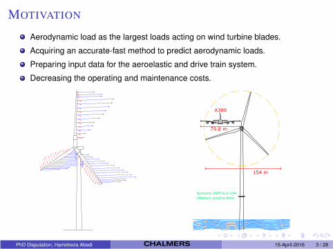
MOTIVATION
Aerodynamic load as the largest loads acting on wind turbine blades.
Acquiring an accurate-fast method to predict aerodynamic loads.
Preparing input data for the aeroelastic and drive train system.
Decreasing the operating and maintenance costs.
PhD Disputation, Hamidreza Abedi 15-April-2016 3 / 28
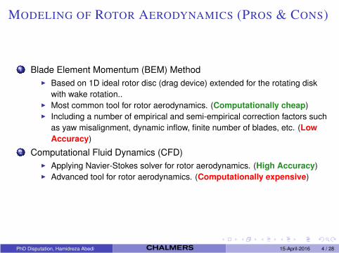
MODELING OF ROTOR AERODYNAMICS (PROS & CONS)
1 Blade Element Momentum (BEM) Method
Based on 1D ideal rotor disc (drag device) extended for the rotating disk
with wake rotation.. Most common tool for rotor aerodynamics. (Computationally cheap) Including a number of empirical and semi-empirical correction factors such
as yaw misalignment, dynamic inflow, finite number of blades, etc. (Low
Accuracy)
2 Computational Fluid Dynamics (CFD)
Applying Navier-Stokes solver for rotor aerodynamics. (High Accuracy) Advanced tool for rotor aerodynamics. (Computationally expensive)
PhD Disputation, Hamidreza Abedi 15-April-2016 4 / 28
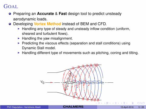
GOAL
Preparing an Accurate & Fast design tool to predict unsteady
aerodynamic loads.
Developing Vortex Method instead of BEM and CFD. Handling any type of steady and unsteady inflow condition (uniform,
sheared and turbulent flows). Handling the yaw misalignment. Predicting the viscous effects (separation and stall conditions) using
Dynamic Stall model. Handling different type of movements such as pitching, coning and tilting.
PhD Disputation, Hamidreza Abedi 15-April-2016 5 / 28
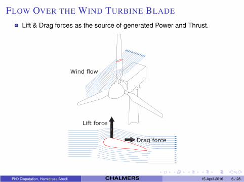
FLOW OVER THE WIND TURBINE BLADE
Lift & Drag forces as the source of generated Power and Thrust.
PhD Disputation, Hamidreza Abedi 15-April-2016 6 / 28
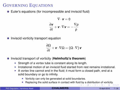
GOVERNING EQUATIONS
Euler’s equations (for incompressible and inviscid fluid)
∇ ·v = 0
∂v
∂t+v ·∇v =−
∇p
ρ
Inviscid vorticity transport equation
∂Ω
∂t+v ·∇Ω = (Ω ·∇)v
Inviscid transport of vorticity (Helmholtz’s theorem)
Strength of a vortex tube is constant along its length. Irrotational motion of an inviscid fluid started from rest remains irrotational. A vortex line cannot end in the fluid; it must form a closed path, end at a
solid boundary or go to infinity.
⋆ Vorticity can only be generated at solid boundaries.⋆ Replacing the solid surface in contact with fluid by a distribution of vorticity.
PhD Disputation, Hamidreza Abedi 15-April-2016 7 / 28
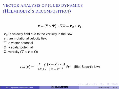
VECTOR ANALYSIS OF FLUID DYNAMICS
(HELMHOLTZ’S DECOMPOSITION)
v = (∇×Ψ)+∇Φ = vω +vp
vω: a velocity field due to the vorticity in the flow
vp: an irrotational velocity field
Ψ: a vector potential
Φ: a scalar potential
Ω: vorticity (∇×v = Ω)
v ind (x) =−1
4π
∫V
(x −x′)×Ω
| x −x′ |3
dx′ (Biot-Savart’s law)
PhD Disputation, Hamidreza Abedi 15-April-2016 8 / 28
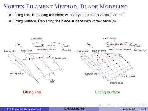
VORTEX FILAMENT METHOD, BLADE MODELING
Lifting line, Replacing the blade with varying strength vortex filament
Lifting surface, Replacing the blade surface with vortex panel(s)
Lifting line Lifting surface
PhD Disputation, Hamidreza Abedi 15-April-2016 9 / 28
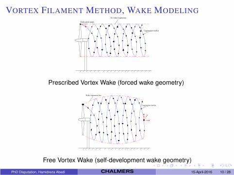
VORTEX FILAMENT METHOD, WAKE MODELING
Prescribed Vortex Wake (forced wake geometry)
Free Vortex Wake (self-development wake geometry)
PhD Disputation, Hamidreza Abedi 15-April-2016 10 / 28
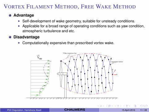
VORTEX FILAMENT METHOD, FREE WAKE METHOD
Advantage
Self-development of wake geometry, suitable for unsteady conditions. Applicable for a broad range of operating conditions such as yaw condition,
atmospheric turbulence and etc.
Disadvantage
Computationally expensive than prescribed vortex wake.
PhD Disputation, Hamidreza Abedi 15-April-2016 11 / 28
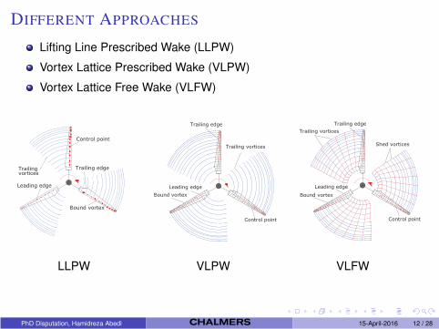
DIFFERENT APPROACHES
Lifting Line Prescribed Wake (LLPW)
Vortex Lattice Prescribed Wake (VLPW)
Vortex Lattice Free Wake (VLFW)
LLPW VLPW VLFW
PhD Disputation, Hamidreza Abedi 15-April-2016 12 / 28
Aerodynamic Load Calculation
PhD Disputation, Hamidreza Abedi 15-April-2016 13 / 28
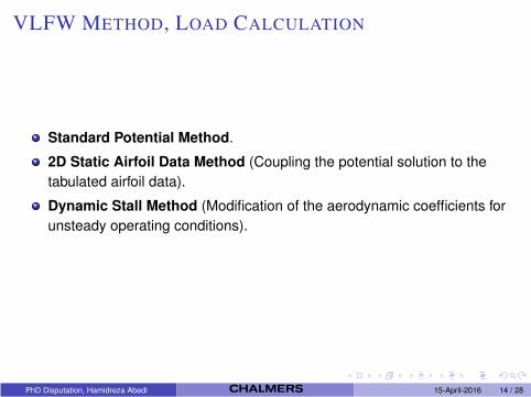
VLFW METHOD, LOAD CALCULATION
Standard Potential Method.
2D Static Airfoil Data Method (Coupling the potential solution to the
tabulated airfoil data).
Dynamic Stall Method (Modification of the aerodynamic coefficients for
unsteady operating conditions).
PhD Disputation, Hamidreza Abedi 15-April-2016 14 / 28
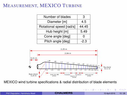
MEASUREMENT, MEXICO TURBINE
Number of blades 3
Diameter [m] 4.5
Rotational speed [rad/s] 44.45
Hub height [m] 5.49
Cone angle [deg] 0
Pitch angle [deg] -2.3
MEXICO wind turbine specifications & radial distribution of blade elements
PhD Disputation, Hamidreza Abedi 15-April-2016 15 / 28
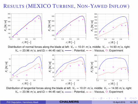
RESULTS (MEXICO TURBINE, NON-YAWED INFLOW)
0.2 0.4 0.6 0.8 150
100
150
200
250
300
350
r/R [−]
Fn[N
/m]
0.2 0.4 0.6 0.8 1
100
200
300
400
500
ag replacements
r/R [−]
Fn[N
/m]
0.2 0.4 0.6 0.8 1100
200
300
400
500
600
700
800
900
r/R [−]
Fn[N
/m]
Distribution of normal forces along the blade at left: V∞ = 10.01 m/s, middle: V∞ = 14.93 m/s, right:
V∞ = 23.96 m/s, and Ω = 44.45 rad/s, : Potential, : Viscous, : Experiment
0.2 0.4 0.6 0.8 10
5
10
15
r/R [−]
Ft[N
/m]
0.2 0.4 0.6 0.8 1
10
20
30
40
50
60
r/R [−]
Ft[N
/m]
0.2 0.4 0.6 0.8 10
50
100
150
200
r/R [−]
Ft[N
/m]
Distribution of tangential forces along the blade at left: V∞ = 10.01 m/s, middle: V∞ = 14.93 m/s, right:
V∞ = 23.96 m/s, and Ω = 44.45 rad/s, : Potential, : Viscous, : Experiment
PhD Disputation, Hamidreza Abedi 15-April-2016 16 / 28
Wake Aerodynamics
PhD Disputation, Hamidreza Abedi 15-April-2016 17 / 28
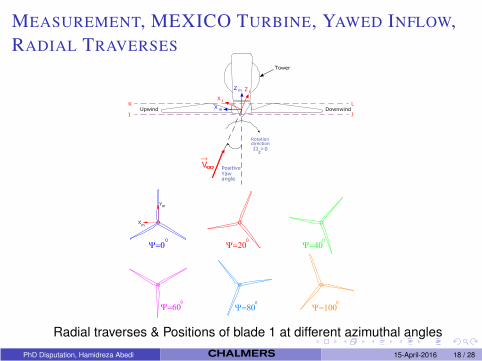
MEASUREMENT, MEXICO TURBINE, YAWED INFLOW,
RADIAL TRAVERSES
Radial traverses & Positions of blade 1 at different azimuthal angles
PhD Disputation, Hamidreza Abedi 15-April-2016 18 / 28
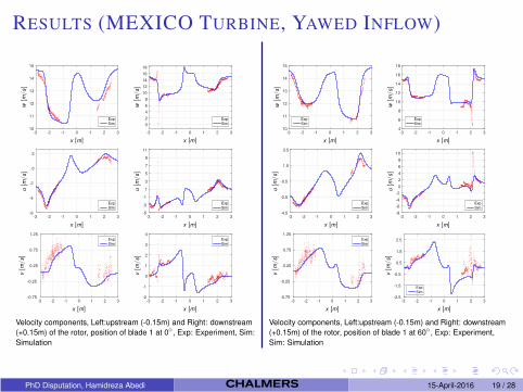
RESULTS (MEXICO TURBINE, YAWED INFLOW)
-3 -2 -1 0 1 2 310
11
12
13
14
15
ExpSim
x [m]
w[m
/s]
-3 -2 -1 0 1 2 3
0
2
4
6
8
10
12
14
16
18
ExpSim
x [m]w[m
/s]
-3 -2 -1 0 1 2 3-6
-4
-2
0
2
ExpSim
x [m]
u[m
/s]
-3 -2 -1 0 1 2 3-5
-3
-1
1
3
5
7
9
11
ExpSim
x [m]
u[m
/s]
-3 -2 -1 0 1 2 3-0.75
-0.25
0.25
0.75
1.25ExpSim
x [m]
v[m
/s]
-3 -2 -1 0 1 2 3-2
-1
0
1
2
3
4ExpSim
x [m]
v[m
/s]
Velocity components, Left:upstream (-0.15m) and Right: downstream
(+0.15m) of the rotor, position of blade 1 at 0 , Exp: Experiment, Sim:
Simulation
-3 -2 -1 0 1 2 310
11
12
13
14
15
ExpSim
x [m]
w[m
/s]
-3 -2 -1 0 1 2 34
6
8
10
12
14
16
18
ExpSim
x [m]
w[m
/s]
-3 -2 -1 0 1 2 3-4.5
-2.5
-0.5
1.5
3.5
ExpSim
x [m]
u[m
/s]
-3 -2 -1 0 1 2 3-8
-6
-4
-2
0
2
4
6
8
10
ExpSim
x [m]
u[m
/s]
-3 -2 -1 0 1 2 3-0.75
-0.25
0.25
0.75
1.25ExpSim
x [m]
v[m
/s]
-3 -2 -1 0 1 2 3-2.5
-1.5
-0.5
0.5
1.5
2.5
ExpSim
x [m]
v[m
/s]
Velocity components, Left:upstream (-0.15m) and Right: downstream
(+0.15m) of the rotor, position of blade 1 at 60 , Exp: Experiment,
Sim: Simulation
PhD Disputation, Hamidreza Abedi 15-April-2016 19 / 28
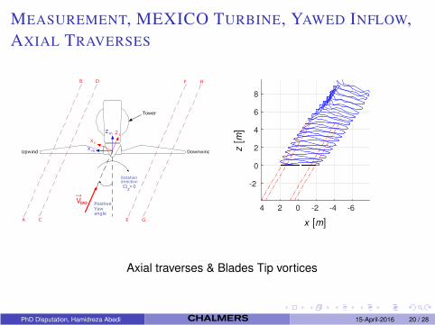
MEASUREMENT, MEXICO TURBINE, YAWED INFLOW,
AXIAL TRAVERSES
-2
0
2
4
6
8
-6-4-2024
x [m]
z[m
]
Axial traverses & Blades Tip vortices
PhD Disputation, Hamidreza Abedi 15-April-2016 20 / 28
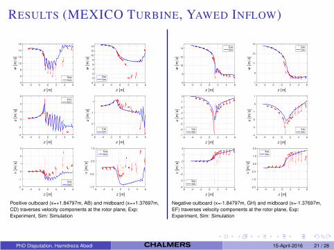
RESULTS (MEXICO TURBINE, YAWED INFLOW)
-6 -4 -2 0 2 4 64
6
8
10
12
14
16
Exp
Sim
z [m]
w[m
/s]
-6 -4 -2 0 2 4 6-2
0
2
4
6
8
10
12
14
ExpSim
z [m]w[m
/s]
-6 -4 -2 0 2 4 6-4
-2
0
2
4
6ExpSim
z [m]
u[m
/s]
-6 -4 -2 0 2 4 6-5
-3
-1
1
ExpSim
z [m]
u[m
/s]
-6 -4 -2 0 2 4 6-2
-1
0
1
2
3
Exp
Sim
z [m]
v[m
/s]
-6 -4 -2 0 2 4 6-1.5
-0.5
0.5
1.5ExpSim
z [m]
v[m
/s]
Positive outboard (x=+1.84797m, AB) and midboard (x=+1.37697m,
CD) traverses velocity components at the rotor plane, Exp:
Experiment, Sim: Simulation
-6 -4 -2 0 2 4 66
8
10
12
14ExpSim
z [m]
w[m
/s]
-6 -4 -2 0 2 4 67
9
11
13
15ExpSim
z [m]
w[m
/s]
-6 -4 -2 0 2 4 6-7
-6
-5
-4
-3
-2
-1
0
ExpSim
z [m]
u[m
/s]
-6 -4 -2 0 2 4 6-4
-3
-2
-1
0
1
ExpSim
z [m]
u[m
/s]
-6 -4 -2 0 2 4 6-4
-3
-2
-1
0
1
2
ExpSim
z [m]
v[m
/s]
-6 -4 -2 0 2 4 6-2.5
-1.5
-0.5
0.5
1.5
2.5ExpSim
z [m]
v[m
/s]
Negative outboard (x=-1.84797m, GH) and midboard (x=-1.37697m,
EF) traverses velocity components at the rotor plane, Exp:
Experiment, Sim: Simulation
PhD Disputation, Hamidreza Abedi 15-April-2016 21 / 28
Turbulent & Sheared Inflow
PhD Disputation, Hamidreza Abedi 15-April-2016 22 / 28
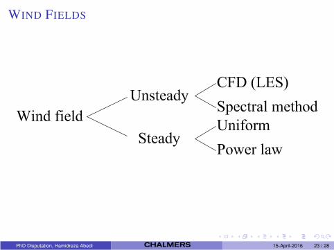
WIND FIELDS
PhD Disputation, Hamidreza Abedi 15-April-2016 23 / 28
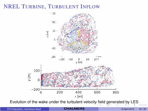
NREL TURBINE, TURBULENT INFLOW
Evolution of the wake under the turbulent velocity field generated by LES
PhD Disputation, Hamidreza Abedi 15-April-2016 24 / 28
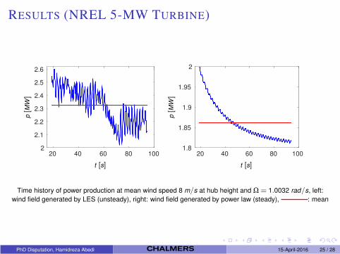
RESULTS (NREL 5-MW TURBINE)
20 40 60 80 1002
2.1
2.2
2.3
2.4
2.5
2.6
t [s]
p[M
W]
20 40 60 80 1001.8
1.85
1.9
1.95
2
t [s]p[M
W]
Time history of power production at mean wind speed 8 m/s at hub height and Ω = 1.0032 rad/s, left:
wind field generated by LES (unsteady), right: wind field generated by power law (steady), : mean
PhD Disputation, Hamidreza Abedi 15-April-2016 25 / 28
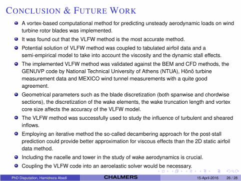
CONCLUSION & FUTURE WORK
A vortex-based computational method for predicting unsteady aerodynamic loads on wind
turbine rotor blades was implemented.
It was found out that the VLFW method is the most accurate method.
Potential solution of VLFW method was coupled to tabulated airfoil data and a
semi-empirical model to take into account the viscosity and the dynamic stall effects.
The implemented VLFW method was validated against the BEM and CFD methods, the
GENUVP code by National Technical University of Athens (NTUA), Hono turbine
measurement data and MEXICO wind tunnel measurements with a quite good
agreement.
Geometrical parameters such as the blade discretization (both spanwise and chordwise
sections), the discretization of the wake elements, the wake truncation length and vortex
core size affects the accuracy of the VLFW model.
The VLFW method was successfully used to study the influence of turbulent and sheared
inflows.
Employing an iterative method the so-called decambering approach for the post-stall
prediction could provide better approximation for viscous effects than the 2D static airfoil
data method.
Including the nacelle and tower in the study of wake aerodynamics is crucial.
Coupling the VLFW code into an aeroelastic solver would be necessary.
PhD Disputation, Hamidreza Abedi 15-April-2016 26 / 28
ACKNOWLEDGMENTS
This work was financed through the Swedish Wind Power Technology Centre
(SWPTC).
The technical support of National Technical University of Athens (NTUA) is
greatfully acknowledged.
MEXICO data: The consortium which carried out the EU FP5 project Mexico,
’Model rotor EXperiments In COntrolled conditions’.
CFD data for NREL 5-MW turbine: Denmark Technical University (DTU), Danish
Energy Agency (EUDP project j.nr. 64011-0094) and the Ministry of Science
(DSF project Sagsnr. 12-130590).
PhD Disputation, Hamidreza Abedi 15-April-2016 27 / 28

Thanks for Your Attention
PhD Disputation, Hamidreza Abedi 15-April-2016 28 / 28