DEVELOPMENT OF Open Source COMPASS SDR · DEVELOPMENT OF Open Source COMPASS SDR Submitted by:- ......
50
DEVELOPMENT OF Open Source COMPASS SDR Submitted by:- JAY PRAKASH and Adarsh Khandelwal B Tech, Part IV Electronics Engineering, IIT (BHU)
Transcript of DEVELOPMENT OF Open Source COMPASS SDR · DEVELOPMENT OF Open Source COMPASS SDR Submitted by:- ......

1 | P a g e
DEVELOPMENT OF Open Source COMPASS SDR
Submitted by:-
JAY PRAKASH and
Adarsh Khandelwal
B Tech, Part IV
Electronics Engineering, IIT (BHU)
IT BHU, VARANASI,INDIA

An OpenSource COMPASS/BEIDOU Software Defined
Receiver
A DESERTATION SUBMITTED AS PARTIAL FULFILLMENT OF
REQUIREMENT OF THE AWARD OF DEGREE
BACHELOR OF TECHNOLOGY
IN ELECTRONICS ENGINEERING
UNDER THE GUIDANCE OF SUPERVISOR: Dr. K.P.SINGH
SUBMITTED BY
JAY PRAKASH (09105EN028) ADARSH KHANDELWAL (09105EN035)
DEPARTMENT OF ELECTRONICS ENGINEERING
INDIAN INSTITUTE OF TECHNOLOGY
(BHU), VARANASI.

CONTENTS
1. Summary
2.1 Need of Compass SDR
2.2BeiDou System Overview
2.3 Receiver Architecture
3.1 Signal processing
3.2 Acquisition
3.3 Tracking
3.4 Navigation data decoding 3.5 Transformation from PZ90.02 to WGS84
3. Final navigation solution 4. Bibliography

SUMMARY
Software-defined radio receivers (SDR) is a concept for transceivers in which the signal processing is accomplished via a programmable general-purpose microprocessor or digital signal processor (DSP), as opposed to an application-specific integrated circuit (ASIC). A software receiver differs from a hardware receiver by performing correlations in software running on a general purpose microprocessor. It can afford batch data processing options that are not available in hardware implementations. New frequencies and new pseudo-random number (PRN) codes can be used simply by making software changes. SDR are not only research tools for the development and test of new navigation and positioning algorithms. The flexibility of software architectures enables them to record several pieces of information that are not limited to position and velocity. Correlator and discriminator outputs, frequency and phase lock indicators and several synchronization messages are just a few examples of the parameters that a software receiver makes available to users and researchers. And the software receiver could be reprogrammed to adjust a new navigation system, which provides an added benefit from the use of the software radio architecture. Along with the decrease of the required processing time, the high configurability, high development speed, low cost software receiver is obtaining more people's favors.
In this paper, a complete Intermediate Frequency (IF) Software COMPASS Receiver was developed using matlab code. It can be used for acquisition, tracking, and calculating position for the COMPASS B1I and B2I signals.
Then after multi-core programming capability of Matlab have been exploited to insure parallel processing for three constellation and combining the results using proper algorithms for more precise coordinates.

Need of the SDR
Perfect and precise positioning have always been a thing of importance be it for military purposes, civilian usage or navigation (indoor and aircrafts).With advent of newer constellations in the group:-GLONASS,GALILEO,COMPASS,GAGAN and many more to come in the list we can be assured of getting unparallel accuracy and precision.
There are two points of concern:-
1. Designing Software Defined Receiver for Compass as they have insured minimum no of satellite in the constellation ie 4.This will insure better PVT results in combination with other available constellations forming an augmented receiver. After acquisition and tracking have been done it would be mainly focusing on decoding of data and finding pseudo-ranges and PVT solutions.
2. As the hardware receiver designs are not open source and non-reconfigurable, software base gives lots of freedom to each user to change algorithms at any level in the highly modular structure of the receiver.
This project shall benefit numerous researchers, students and developers around the world in understanding the core working of GNSS acquisition, tracking and post-navigation processing of the raw GNSS samples.
We well know we need to constantly update and change algorithms to achieve more better results and design a robust model in itself.
With such a large pool of GNSS researchers and open source contributors something know to all and within reach can help in rigorous and dynamic updates of the model we are developing. Each could add with changes and see if results improve in varied conditions. The platform shall seek mutual development be it in signal processing, algorithms or architectural modifications.
Finally we would have a model being worked upon by hundreds and thousands of minds and the GNSS would not be a thing of industries and high end institutions but within reach of civilians and then can configure whatever and whenever they want.
Ultimately we have a full fledge receiver to get PVT solutions using varied constellations.
Applications of Compass are equivalent to those of GPS and other constellations and can be seen mostly in highly precise navigation of land, sea, air and low orbiting spacecraft .Besides this, Compass is also suitable for the dissemination of highly precise global and local time scales as well as for establishing global geodetic coordinate systems and local geodetic networks. The system can also be used for providing precise coordinates for cadastre works. Further usage could contain the support of research work in geology, geophysics, geodynamics, oceanography and others by providing position and time information. Similar uses are possible for large scale construction projects.

With this range of applications and the achievable accuracy, Compass has become an attractive tool for navigational and geodetic purposes. But not only Compass as a stand-alone system draws the interest of scientists around the world. The fact that there are two independent, but generally very similar satellite navigation systems also draws attention to the combined use of both systems. This combined use brings up a number of advantages. At first, the number of observable satellites is increased with respect to one single system. This will provide a user with a better satellite geometry and more redundant information, allowing him to compute a more accurate position fix. In cases with obstructed visibility of the sky, such as mountainous or urban areas, a position fix might not be possible at all without these additional satellites. Besides that, the more satellite measurements are available, the earlier and more reliably a user can detect and isolate measurement outliers or even malfunctioning satellites. Thus, the combined use of GPS , Compass, Galileo and GLONASS may aid in Receiver Autonomous Integrity Monitoring (RAIM), providing better integrity of the position fix than a single system alone.

BeiDou System Overview
Space Constellation
BeiDou Navigation Satellite System is called BeiDou System for short,with the abbreviation
as BDS. When fully deployed, the space constellation of BDS consists of five Geostationary
Earth Orbit (GEO) satellites, twenty-seven Medium Earth Orbit (MEO) satellites and three
Inclined Geosynchronous Satellite Orbit (IGSO) satellites. The GEO satellites are operating in
orbit at an altitude of 35,786 kilometers and positioned at 58.75°E, 80°E, 110.5°E, 140°E and
160°E respectively. The MEO satellites are operating in orbit at an altitude of 21,528 kilometers
and an inclination of 55° to the equatorial plane. The IGSO satellites are operating in orbit at
an altitude of 35,786 kilometers and an inclination of 55° to the equatorial plane.
By the end of 2012, there are five GEO, four MEO and five IGSO BeiDou navigation satellites in
orbit.
Coordinate System
BDS adopts the China Geodetic Coordinate System 2000 (CGCS2000), and the definition is
listed below:
The origin is located at the mass center of the Earth;
The Z-axis is in the direction of the IERS (International Earth Rotation and
Reference System Service) Reference Pole (IRP);
The X-axis is directed to the intersection of IERS Reference Meridian (IRM) and the plane
passing the origin and normal to the Z-axis;
The Y-axis, together with Z-axis and X-axis, constitutes a right handed orthogonal
coordinate system. The origin of the CGCS2000 is also the geometric center of the CGCS2000
ellipsoid, and the Z-axis is the rotation axis of the CGCS2000 ellipsoid. The parameters of
the CGCS2000 ellipsoid are as follows:
Semi-major axis: a = 6378137.0 m
Geocentric gravitational constant (mass of the earth atmosphere included):
μ = 3.986004418*10^14
Flattening: f = 1/298.257222101
Rate of earth rotation: 7.2921150*10^-5

Time System
The time reference for the BDS uses the BeiDou navigation satellite system Time (BDT).
BDT adopts international system of units (SI) seconds, rather than leap seconds, as the
basic unit for continuous accumulation. The start epoch of BDT was 00:00:00 on January 1,
2006 of Coordinated Universal Time (UTC). BDT is counted with week and seconds of week
(SOW). BDT is related to the UTC through UTC(NTSC). BDT offset with respect to UTC is
controlled within 100 nanoseconds (modulo 1 second). The leap seconds are broadcast in
navigation (NAV) message.
Signal Specifications
Signal Structure
The B1 signal is the sum of channel I and Q which are in phase quadrature of each other. The
ranging code and NAV message are modulated on carrier. The signal is composed of the
carrier frequency, ranging code and NAV message.
The B1 signal is expressed as follows:

Signal Characteristics
1. Carrier Frequency
The nominal frequency of B1I signal is 1561.098 MHz.
2. Modulation Mode
The transmitted signal is modulated by Quadrature Phase Shift Keying (QPSK).
3. Carrier Phase Noise
The phase noise spectral density of the unmodulated carrier is as follows:
4. Signal Multiplexing Mode
The signal multiplexing mode is Code Division Multiple Access (CDMA).
5. Satellite Signal Bandwidth and Out-band Suppression
(1)Bandwidth (1 dB): 4.092 MHz (centered at carrier frequency of B1I);
Bandwidth (3 dB): 16 MHz (centered at carrier frequency of B1I).
(2)Out-band suppression: no less than 15 dB on f 0 ±30 MHz, where f 0 is the carrier
frequency of B1I signal.
6. Spurious
In-band spurious shall be at least 50 dB below the unmodulated carrier of B1I over the satellite
signal bandwidth (1 dB).
7. Signal Coherence
(1) The random jitter of the initial phase difference between the ranging code modulated on
carrier and carrier is less than 3° (1σ) (relative to the carrier) for B1I signal.
(2) Carrier phase quadrature difference between channel I and Q is less than 5° (1σ).

8. Equipment Group Delay Differential
Equipment group delay is defined as the delay between the antenna phase center of a
satellite and the output of the satellite onboard frequency source. The equipment group
delay differential of B1I is given as T GD1 in NAV message with uncertainty less than 1
nanosecond (1σ).
9. Ranging Code on B1I
The chip rate of the B1I ranging code is 2.046 Mcps, and the length is 2046 chips. The
B1I ranging code (hereinafter referred to as C B1I ) is a balanced Gold code truncated with
the last one chip. The Gold code is generated by means of Modulo-2 addition of G1 and G2
sequences which are respectively derived from two 11-bit linear shift registers.
The generator polynomials for G1 and G2 are as follows:
The different phase shift of G2 sequence is accomplished by respective tapping in the
shift register generating G2 sequence. By means of Modulo-2 addition of G2 with different
phase shift and G1, a ranging code is generated for each satellite.

The phase assignment of G2 sequence is shown:-

Receiver Architecture
Antenna
It consists of five modules: an antenna, a RF front-end, acquisition module, ‘n’ receiver channels and position calculation module. The antenna and RF front-end devices are the only hardware devices of the system. The RF front-end device is necessary to down convert the COMPASS signal to an intermediate frequency (IF), sample the IF signal and digitize it. The present CPU capacity is still unable to process the COMPASS signal directly from the antenna in completely software-based approach. Thus a RF front-end device is still necessary. In conventional hardware-based receiver, the three blocks in the dashed textbox in Figure are implemented in an IC chip and hence the user does not have a free access to the algorithms built inside the chips. In software-based receiver, these blocks are fully implemented using high level programming languages and hence the user has complete control over the algorithms. This is the main difference between the software receiver and a conventional hardware receiver. The acquisition module mainly complete three tasks: finding satellites visible to the receiver, finding coarse values for B1 code or B2 code phase and carrier frequency for each satellite. A receiver channel includes six functional blocks: code tracking, carrier tracking, bit synchronization, navigation data decoding, satellite position calculating and pseudo-range calculating, as shown in Figure 2. The detail description of each functional block can be found in references.
Pre Amplifier Down Converter IF Sampling
Tracking Loop Navigation message
Extraction
Measurements
Navigation Solution

COMPASS SDR
The final goal of a GNSS receiver is computing the position and velocity of the receiver or at least providing some measurements which can be used to compute these values. For this purpose, the received signals at antenna must be acquired and tracked. After tracking, navigation message can be extracted and utilized to generate some measurements that are useful in computing the navigation solution.
Plot of raw data obtained from frontend

Signal Processing
The received signal at the antenna is amplified and then down converted to the desired intermediate frequency (IF). The down converted signal is sampled and sent to the signal processor block. Amplification, down conversion and sampling are performed in the radio frequency (RF) front-end block. The signal processor block consists of tracking loop as well as navigation message extraction and measurement generation components. One signal processing block is assigned for each satellite signal being tracked and is herein simply called a “channel”. Generally, a signal tracking loop consists of the following components. • Doppler removal component in which the carrier part of the received signal is removed • Correlation component in which the ranging code part of the received signal is removed • Discriminator component which can compute the difference (error) between the locally generated signals and the received ones • Loop filter component which smoothes the output of the discriminators
Timing and clock management The receiver was designed to work with different sampling rates and sampling resolutions. The fundamental receiver timing reference, used to time-stamp the signal reception time, is established by synchronizing a receiver “clock” using the first sample of data in a given sub-frame. The COMPASS time of this sub-frame boundary is transmitted in the navigation data message and effectively allows the locally maintained, data sample–based, receiver clock to be set relatively accurately with respect to COMPASS time. However, this internal receiver clock will not be exactly synchronized to COMPASS time and must be constantly corrected using the output of the position solution. The inexact frequency of the sampled data will cause the signal receive time to contain a bias with respect to COMPASS time. However, by constantly correcting the receiver time as part of the navigation solution and propagating it forward as new data is read in based on the data sample frequency, it can be maintained close enough to COMPASS system time to make measurements. The second half of the timing problem is determining the time of transmission of the satellite signals at a given data sample. The receiver recorded the exact sample where the satellite sub-frame was identified. The time at this sub-frame obtained from the navigation data, combined with data bits and 1-ms-code epochs allows the receiver to calculate the signal transmission time at any sample. This is successful due to the very accurate clocks generating the signals on board the satellites.

Main processing loop The startup and main processing modules are shown in Figure. These do not represent individual functions but the high-level processing states that the receiver progresses through, ultimately advancing to the navigation state, where the receiver PVT is estimated. The initialization of the receiver consists primarily of reading the configuration file, initializing internal variables and performing miscellaneous set up tasks. The initialization sequence is only executed once for every run of the receiver.
Frequency and code Phase for each satellite Prompt I and sample no For each satellite after tracking acquired satellites
Positions solutions
Flow diagram for COMPASS SDR
PostProcessing.m
Ask for data file
Create data
vectors
Tracking.m
Acquisition.m
postNavigation.m
End

ACQUISITION
The acquisition functions of the receiver were designed to be flexible. An outline of the acquisition processing is shown in Figure. The acquisition steps of the receiver are as follows: (1) Gather a reasonable amount of data for use in the FFT acquisition processing. The default value is currently 4 ms of data samples. (2) When enough data has been collected, call the acquire function, specifying the satellite to search for and scan over a wide range of coarse Doppler bins by performing the following steps:
a) Perform FFT on input sample buffer.
b) b)Multiply sample FFT and pre-calculated PRN code FFT;
c) Perform inverse FFT;d) Search for peaks exceeding the detection threshold.
(3) If a satellite signal is found, then:
a) Perform fine Doppler search and store results;
b) Perform debug searches if specified in the configuration file;
c) Allocate it to a tracking channel.

The flow chart of the algorithm is as shown below: Acquisition.m
Read input signal
Create two vectors of data (Signal1 and signal2)
Loop initialisation
PRN = 1:no of satellites
Generate local signals
Loop initialisation
j = 1:no of freq bins
Remove carrier signal &
convert to freq domain
Correlate with Range
code (multiply in freq
domain)
See for maximum power
and store for bin
Look for Correlation peak
and store carrier
frequency
Find code phase of the
same correlation peak
Find the second highest
correlation peak
If peakMetric>threshold
Store acqRes for PRN

Acquisition Result Plot Acquisition Metric was compared to a predefined empirical value of 3 and satellites with values greater than 3 were tracked using tracking.m file. Acquired Satellites Channel nos.:- 1. 7
1. 10 2. 13 3. 14

TRACKING Tracking loop overview The objective of a tracking loop is determining the difference between the locally generated signal and the incoming pseudo-base-band signal, filtering that estimate and sending new information to the signal generators. In a tracking loop process, both carrier and code signals are accurately reproduced inside the receiver. For each carrier and code portion of the received signal, a tracking loop exists. The code tracking loop is called a delay lock loop (DLL) and must provide an estimate of code phase of the ranging code being tracked. The carrier tracking loop is called carrier lock loop (CLL) and it must track the incoming carrier phase via a phase lock loop (PLL) or a carrier frequency via frequency lock loop (FLL). The carrier phase yields more accurate information needed for navigation message decoding. Two tracking loops can be coupled in some cases where the DLL needs an accurate estimate of the incoming carrier frequency which the CLL can provide. Tracking algorithm for GLONASS is similar to that of the GPS with no major changes as such. The prime importance is using different carrier frequencies (obtained from acquisition.m in acqResults structure) in PLL for each tracking channel. And codes would remain same for all DLL loops unlike GPS though they will be of three types:-E(early),P(prompt) and D(delay) like GPS. Phase lock loop The objective of a phase lock loop (PLL) is to generate the carrier portion of the locally generated signal. The discriminator in phase lock loop determines the difference between the phase of the locally generated carrier signal and the received pseudo-base-band signal. The output of the discriminator is sent to the NCO to generate a new reference signal. In Figure 4-3, the carrier tracking loop is highlighted with green color. PLL is sensitive to data bit transitions. Specifically, when the navigation data bit changes from one to zero or from zero to one, a 180° phase change is detected by the PLL and it therefore attempts to correct the perceived error. As such, a discriminator that is insensitive to bit transitions is preferred. These types of discriminators are termed Costas discriminators. In Costas discriminators, Doppler removed and correlated I channel and Q channel are used. The PLL discriminator used for GLONASS phase lock loop is a two-quadrant arctangent Costas discriminator. Delay lock loop The objective of a delay lock loop (DLL) is to track the standard ranging code of the received pseudo-base-band signal by generating a local standard ranging code. This loop consists of correlator, accumulator, DLL discriminator and loop filter .The inputs to the DLL are Doppler removed samples modulated with navigation data and ranging code. To remove this ranging code, it is required to generate three pairs of I and Q values; early (IE, QE), prompt or punctual (IP, QP), and late (IL, QL), where E, P, and L subscripts stand for early, punctual and laterespectively. Early and late values are typically one chip away from each other and are half chip spaced from the prompt value.There are two types of DLL discriminators: 1. Coherent discriminator: where all power is on I channel, implying phase lock is achieved. 2. Non-coherent discriminator: where phase lock is not required. Loop filters The objective of a loop filter is to reduce the effect of noise on the discriminator output signal in order to generate an accurate and smooth estimate of the original signal at its output and to pass this information to the NCO. A loop filter rejects as much noise as possible and responds to the changes in

signals which are caused by both receiver and satellite dynamics (Ward et al 2006). Satellites dynamics cause Doppler changes up to 0.9 Hz/s and receiver dynamics causes additional changes, wither higher acceleration causing faster changes in Doppler .The loop filter order and noise bandwidth are two main parameters of a loop filter. By carefully choosing these parameters, the performance of a tracking loop can increase significantly. The block diagram of a complete tracking channel on the GLONASS receiver.
The software correlator has the task of generating the code and carrier replica signals and performing the necessary correlations and accumulations needed to feed into the tracking functions. When the number of samples processed is equal to a complete code period (1 ms for COMPASS B1/B2 code) the tracking loop function is called. The correlator continually computes results on six separate correlator spacings for each channel at every sample. These include prompt correlators for the in-phase
Integrate +Dump
NCO Carrier
generator Carrier Loop
Discriminator
Code Loop
Discriminator
Carrier Loop
Filter
90
Integrate +Dump
Integrate +Dump
Integrate +Dump
Integrate +Dump
Integrate +Dump
PRN Code
Generator Incoming
Signal

(I) and quadrature (Q) signals components, as well as early and late offset correlators for each. The early and later correlators are spaced one-half chip from the prompt value, and are used primarily in calculating the tracking loop feedback values. At the start of each pass through the tracking loops, the accumulated correlator measurements are used to calculate an error in the replica signal alignment, which is then used to adjust the carrier and code increments used in the correlator for the next set of samples. The tracking error is determined using a discriminator function based on a combination of the six available accumulations calculated for each channel by the software correlator function. This discriminator value is used to calculate new values for the code and carrier increments, which are then fed back into the carrier and code replica generator to be applied during the next correlation interval. TRACK RESULT
Afore shown Plot shows the navigation bits extracted by tracking.m program along with PLL and DLL Discriminators plots. Magnified view of the navigation message clearly showing data bits which can now be extracted by postNavigation.m

NAVIGATION DATA DECODING
NAV Message Classification
NAV messages are formatted in D1 and D2 based on their rate and structure. The rate of D1 NAV message which is modulated with 1 kbps secondary code is 50 bps. D1 NAV message contains basic NAV information (fundamental NAV information of the broadcasting satellites, almanac information for all satellites as well as the time offsets from other systems); while D2 NAV message contains basic NAV and augmentation service information (the BDS integrity, differential and ionospheric grid information) and its rate is 500 bps.The NAV message broadcast by MEO/IGSO and GEO satellites is D1 and D2 respectively.
Data Error Correction Coding Mode
The NAV message encoding involves both error control of BCH(15,11,1) and interleaving. The BCH code is 15 bits long with 11 information bits and error correction capability of 1 bit. The generator polynomial is g(X)=X^4+X+1. The NAV message bits are grouped every 11 bits in sequence first. The serial/parallel conversion is made and the BCH(15,11,1) error correction encoding is performed in parallel. Parallel/serial conversion is then carried out for every two parallel blocks of BCH codes by turns of 1 bit to form an interleaved code of 30 bits length. The implementation is shown
D1 NAV Message Secondary Code Modulated on D1 For D1 NAV message in format D1 of rate 50 bps a secondary code of Neumann-Hoffman (NH) code is modulated on ranging code. The period of NH code is selected as long as the duration of a NAV message bit. The bit duration of NH code is the same as one period of the ranging code. Shown as in Figure, the duration of one NAV message bit is 20 milliseconds and the ranging code period is 1 millisecond. Thus the NH code (0, 0, 0, 0, 0, 1, 0, 0, 1, 1, 0, 1, 0, 1, 0, 0, 1, 1, 1, 0) with length of 20 bits, rate 1 kbps and bit duration of 1 millisecond is adopted. It is modulated on the ranging code synchronously with NAV message bit.

D1 NAV Message Frame Structure
The NAV message in format D1 is structured in the superframe, frame and subframe. Every superframe has 36000 bits and lasts 12 minutes. Every superframe is composed of 24 frames (24 pages). Every frame has 1500 bits and lasts 30 seconds. Every frame is composed of 5 subframes. Every subframe has 300 bits and lasts 6 seconds. Every subframe is composed of 10 words. Every word has 30 bits and lasts 0.6 second. Every word consists of NAV message data and parity bits. In the first word of every subframe, the first 15 bits is not encoded and the following 11 bits are encoded in BCH(15,11,1) for error correction. So there is only one group of BCH code contained and there are altogether 26 information bits in the word. For all the other 9 words in the subframe both BCH(15,11,1) encoding for error control and interleaving are involved. Each of the 9 words of 30 bits contains two blocks of BCH codes and there are altogether 22 information bits in it.

Corresponding program responsible for decoding and finding navigation solution:- TrackResults Settings Flow Diagram for postNavigation.m
postNavigation.m
Find Preambles
For i=1:activechnanelList
Copy 15 strings long record from tracking output
Decode Data and
Extract ephemeris info
Initialise current
measurement
calculatePseudoranges
Find satellite position
and clock offset
Calculate
LeastSquarePos
Receiver
Position
Transform from PZ90.02 to WGS84
Coordinate conversion
Store Results

Functions included in postNavigation.m are:-
findPreambles.m
ephemeris.m
satposg.m
calculatePseudoranges.m
leastSquarePos.m
satClkCorr.m
cart2geo.m
cart2utm.m These functions are included in Appendix. A brief overview is as follows. FindPreambles.m:- It finds the first Time Mark occurrence in the bit stream of each channel. The Time Mark is a unique bit sequence ‘111110001101110101000010010110’ .At the same time function returns list of channels, that are in tracking state. Basically tracking output from each channels are correlated with timemarks and positions of timemarks are found by comparing absolute value of correlation to a threshold value.The process thus gives position of timemarks for each channel and mean while keeps track of active channel list too.

Ephemeris.m:- It decodes ephemerides and time of frame start from the given bit stream. The stream (array) in the parameter DATA must contain 30000 bits. The first element in the array must be the first bit of a string. The string number of the first string in the array is not important.
ALGORITHM:-
85 bits out of 15 strings taken from trackResults(channelNr).I_P(subFrameStart(channelNr) +... 300 : subFrameStart(channelNr) + 300 + (1500 * 20) -1) Corresponding to ICD Table no:4.4 and 4.5
Ephemeris.m(for each
channel )
Take 85 data
bits
For i=1:15
(for 15 strings)
Read last four
bits of ‘m’ word
to find string no.
As per decoded
value of ‘m’
(either of 1:5 of
‘m’ ie string no)
get
corresponding
ephemeris
parameters
Only 5 first strings are of interest.
The rest strings contain almanac
that is not used in this program.

Satposg.m:- This function calculates initial position, velocity and acceleration of the satellites in prnList on the transmit Time based on ephemeris data (eph). Based on “CALCULATIONS FOR POSITIONING WITH THE GLOBAL NAVIGATION
SATELLITE SYSTEM” by Chao-heh Cheng August, 1998
Algorithm Transmit time Active PRN List (TOW) Ephemeris Data Flow diagram of satposg.m
Satposg.m
For i=1:no. length(prnList)
Initialize constants
(c20, u, ae, J)
Divide calculation
into subintervals
Delta time between ephemeris issue time and current time.
Integration of equations in direct absolute geocentric
coordinate system using 4th order Runga-Kutta technique as
given in GLONASS ICD(Appendix 3)
Obtain position velocity
acceleration and clock-error

CalculatePseudoranges.m:- CalculatePseudoranges finds relative pseudoranges for all satellites listed in Channel List at the specified millisecond of the processed signal. The pseudoranges contain unknown receiver clock offset. Track results Settings Channel List Flow diagram for CalculatePseudoranges.m
LeastSquarePos.m:- This Function calculates the Least Square Solution for Receiver’s Position Input:- satpos - Satellites positions (in ECEF system: [X; Y; Z;] -one column per satellite) obs - Observations - the pseudorange measurements to each satellite: (e.g. [20000000 21000000 .... .... .... ]) settings - receiver settings Outputs:- pos - receiver position and receiver clock error (in ECEF system: [X, Y, Z, dt]) el - Satellites elevation angles (degrees) az - Satellites azimuth angles (degrees) dop - Dilutions Of Precision ([GDOP PDOP HDOP VDOP TDOP]) The concerned algorithm is similar to that of GPS SDR exactly.
CalculatePseudoranges.m
For i= 1: length(channel list)
Convert travel time to a distance
Truncate the travelTime and compute pseudoranges
Calculate the travel time

Transformation from PZ90.02 to WGS84. After calculation of Receiver position using LeastSquarePos.m it was needed to transform from PZ90.02 to WGS84. satellites broadcast their positions in PZ-90 coordinates as a part of their navigation messages. The navigation message is broadcast by each satellite and usually refreshed every half-hour. The PZ-90 geocentric coordinate frame, specified as an abstract mathematical entity, is just one element of an overall reference system to represent the earth from geometric, gravitational, and geodetic standpoints. Like its counterpart, WGS84 for GPS, PZ-90 is a self-contained and self-consistent system within which to define a 3-D position. A comprehensive description of WGS84 is available from National Imagery and Mapping Agency (NIMA) reports and the description of PZ-90 comes mainly from the GLONASS Interface Control Document .The values of the defining parameters for the PZ-90 gravity model and its ellipsoid are slightly different from those of WGS84. These differences, however, are easily accommodated. A more difficult problem arises from the differences in the ECEF coordinate frames. The ECEF coordinate frames of WGS84 and PZ-90 differ in their formal definitions. While each locates the origin at the center of mass of the earth, the directions of the z axes are different: WGS84 defines it as passing through the instantaneous pole of 1984; PZ-90 adopts instead the average position of the pole between the years 1900 and 1905. This description, however, is not adequate as a basis for determining a transformation between GPS and GLONASS. Actually, even if the formal definitions were identical, it would not have ensured that the coordinates of a point as determined by measurements from the two systems would be identical. The coordinate frame for each system is realized (or, implemented) by adopting the coordinates of a set of stations. A consistent set of such coordinates defines implicitly the ECEF coordinate frame (i.e., an origin, a set of directions for the Cartesian axes, and a scale factor). Therefore, even if GPS and GLONASS had adopted the same definition for the reference coordinate frame, the independent implementation of each system would have kept the two from being identical. A transformation between PZ-90 and WGS84, the coordinate frames used by GLONASS and GPS, respectively, has been studied and implemented in combining measurements from the two systems [29]. From the research results of Lincoln Laboratory, the difference between the two coordinate frames is that the zero meridian (X-axis) of PZ-90 is East of that for WGS84. A small clockwise rotation of 0.4 seconds of arc of the Z-axis of PZ-90 brings the two coordinate frames substantially into coincidence. The residuals are reduced further, though only slightly, by a 2.5 m displacement of the origin along the Y-axis. As shown in Figure 4.1, the estimated transformation between PZ-90 (u, v, w) and WGS84 (x, y, z) is:
x 1 -1.96x10⁻⁶ 0 u ⁼ Y 1.96x10⁻⁶ 1 0 v
Z 0 0 1 w

Final Navigation solution

Bibliography
1. K. Borre, D.M. Akos, N. Bertelsen, P. Rinder, and S.H. Jensen: “A Software-Defined GPS and Galileo Receiver” (ISBN 0-8176-4390-7)
2. Saloomeh Abbasiannik, “Multichannel Dual Frequency GLONASS Software Receiver in Combination with GPS L1 C/A
(URL: http://www.geomatics.ucalgary.ca/research/publications) April 2009
3. Kai Borre, Aalborg University, Dennis Akos, University of Colorado ,“A Software-Defined GPS and Galileo Receiver: Single-Frequency Approach”
4. Chao-heh Cheng; “CALCULATIONS FOR POSITIONING WITH THE GLOBAL NAVIGATION SATELLITE SYSTEM” a Thesis Presented to The Faculty of the Fritz J. and Dolores H. Russ
College of Engineering and Technology Ohio University in Partial Fulfillment Of the Requirement for the Degree Master of Science, August, 1998

Appendix:- 1. Acquisition code
function acqResults = acquisition(longSignal, settings) %Function performs cold start acquisition on the collected "data". It %searches for COMPASS signals of all satellites, which are listed in field %"acqSatelliteList" in the settings structure. Function saves code phase %and frequency of the detected signals in the "acqResults" structure. % %acqResults = acquisition(longSignal, settings) % % Inputs: % longSignal - 11 ms of raw signal from the front-end % settings - Receiver settings. Provides information about % sampling and intermediate frequencies and other % parameters including the list of the satellites to % be acquired. % Outputs: % acqResults - Function saves code phases and frequencies of the % detected signals in the "acqResults" structure. The % field "carrFreq" is set to 0 if the signal is not % detected for the given PRN number.
%--------------------------------------------------------------------------
% Initialization =========================================================
% Find number of samples per spreading code samplesPerCode = round(settings.samplingFreq / ... (settings.codeFreqBasis / settings.codeLength));
% Create two "settings.acqCohIntegration" msec vectors of data % to correlate with: signal1 = longSignal(1:2*samplesPerCode);
% Find sampling period: ts = 1 / settings.samplingFreq;
% Find phase points of the local carrier wave: phasePoints = (0 : (2*samplesPerCode-1)) * 2*pi*ts;
% Number of the frequency bins for the given acquisition band numberOfFrqBins = round(settings.acqSearchBand * 2*1) + 1;
% Generate all C/A codes and sample them according to the sampling freq: caCodesTable = makeCaTable(settings);
%--- Initialize arrays to speed up the code ------------------------------- % Search results of all frequency bins and code shifts (for one satellite) results = zeros(numberOfFrqBins, 1*samplesPerCode); % Carrier frequencies of the frequency bins frqBins = zeros(1, numberOfFrqBins);
%--- Initialize acqResults ------------------------------------------------ % Carrier frequencies of detected signals acqResults.carrFreq = zeros(1, 37); % C/A code phases of detected signals acqResults.codePhase = zeros(1, 37);

% Correlation peak ratios of the detected signals acqResults.peakMetric = zeros(1, 37);
fprintf('(');
% Perform search for all listed PRN numbers ... for PRN = settings.acqSatelliteList
% Correlate signals ====================================================== %--- Perform DFT of C/A code ------------------------------------------ %Multiply C/A code on Neumann-Hoffman code (first 5 ms - otherwise too
long wait time) %NH = "0, 0, 0, 0, 0, 1, 0, 0, 1, 1, 0, 1, 0, 1, 0, 0, 1, 1, 1, 0"; caCodeFreqDom = conj(fft([caCodesTable(PRN, :) zeros(1,
samplesPerCode)]));
%--- Make the correlation for whole frequency band (for all freq. bins) for frqBinIndex = 1:numberOfFrqBins %--- Generate carrier wave frequency grid (freqency step depends % on "settings.acqCohIntegration") -------------------------------- frqBins(frqBinIndex) = settings.IF - ... (settings.acqSearchBand/2) * 1000 + ... (1000 / (2*1)) * (frqBinIndex - 1); %--- Generate local sine and cosine ------------------------------- sigCarr = exp(1i*frqBins(frqBinIndex) * phasePoints); %% a=length(sigCarr); %% fprintf('length os sigcarr is:%d',a);
%% fprintf('samples per code is: %d',samplesPerCode);
%--- "Remove carrier" from the signal and Convert the baseband % signal to frequency domain -------------------------------------- %pause; IQfreqDom1 = fft(sigCarr .* signal1);
%--- Multiplication in the frequency domain (correlation in time
domain) convCodeIQ1 = IQfreqDom1 .* caCodeFreqDom;
%--- Perform inverse DFT and store correlation results ------------ acqRes1 = abs(ifft(convCodeIQ1)) .^ 2;
%--- Check which msec had the greater power and save that, will %"blend" 1st and 2nd "settings.acqCohIntegration" msec but will % correct data bit issues results(frqBinIndex, :) = acqRes1(1:samplesPerCode);
end % frqBinIndex = 1:numberOfFrqBins
% Look for correlation peaks in the results ============================== % Find the highest peak and compare it to the second highest peak % The second peak is chosen not closer than 1 chip to the highest peak
%--- Find the correlation peak and the carrier frequency -------------- [peakSize frequencyBinIndex] = max(max(results,[],2));

%--- Find code phase of the same correlation peak --------------------- [peakSize codePhase] = max(max(results));
%--- Find 1 chip wide CA code phase exclude range around the peak ---- samplesPerCodeChip = round(settings.samplingFreq /... settings.codeFreqBasis); excludeRangeIndex1 = codePhase - samplesPerCodeChip; excludeRangeIndex2 = codePhase + samplesPerCodeChip;
%--- Correct C/A code phase exclude range if the range includes array %boundaries if excludeRangeIndex1 < 2 codePhaseRange = excludeRangeIndex2 : ... (samplesPerCode + excludeRangeIndex1); elseif excludeRangeIndex2 > samplesPerCode codePhaseRange = (excludeRangeIndex2 - samplesPerCode) : ... excludeRangeIndex1; else codePhaseRange = [1:excludeRangeIndex1, ... excludeRangeIndex2 : samplesPerCode]; end
%--- Find the second highest correlation peak in the same freq. bin --- secondPeakSize = max(results(frequencyBinIndex, codePhaseRange));
%--- Store result ----------------------------------------------------- acqResults.peakMetric(PRN) = peakSize/secondPeakSize;
% If the result is above threshold, then there is a signal ... if (peakSize/secondPeakSize) > settings.acqThreshold %--- Indicate PRN number of the detected signal ------------------- fprintf('%02d ', PRN); acqResults.codePhase(PRN) = codePhase; acqResults.carrFreq(PRN) =... settings.IF - ... (settings.acqSearchBand/2) * 1000 + ... (1000 / (2*1)) * (frequencyBinIndex - 1);
else %--- No signal with this PRN -------------------------------------- fprintf('. '); end % if (peakSize/secondPeakSize) > settings.acqThreshold
end % for PRN = satelliteList
%=== Acquisition is over ================================================== fprintf(')\n');
end

2. Acquisition_4ms code function acqResults = acquisition_4x5ms(longSignal, settings) %Function performs cold start acquisition on the collected "data". It %searches for COMPASS signals of all satellites, which are listed in field %"acqSatelliteList" in the settings structure. Function saves code phase %and frequency of the detected signals in the "acqResults" structure. % %acqResults = acquisition(longSignal, settings) % % Inputs: % longSignal - 11 ms of raw signal from the front-end % settings - Receiver settings. Provides information about % sampling and intermediate frequencies and other % parameters including the list of the satellites to % be acquired. % Outputs: % acqResults - Function saves code phases and frequencies of the % detected signals in the "acqResults" structure. The % field "carrFreq" is set to 0 if the signal is not % detected for the given PRN number.
%-----------
% Initialization =========================================================
% Find number of samples per spreading code samplesPerCode = round(settings.samplingFreq / ... (settings.codeFreqBasis / settings.codeLength)); fprintf('%dsamplespercode=\n',samplesPerCode)
%Let's test simple acceleration. Let's resample the signal to lower
frequency.
a=length(longSignal); fprintf('%d longSignal=\n',a); longSignal = reshape(longSignal, settings.acqResampleCoef, ... length(longSignal) / settings.acqResampleCoef);
%longSignal = sum(longSignal, 'r'); longSignal = sum(longSignal); samplesPerCode = samplesPerCode / settings.acqResampleCoef;
% Create two "settings.acqCohIntegration" msec vectors of data % to correlate with: signal1 =
longSignal(0*5*samplesPerCode+1:5*samplesPerCode+1*5*samplesPerCode); signal2 =
longSignal(1*5*samplesPerCode+1:5*samplesPerCode+2*5*samplesPerCode); signal3 =
longSignal(2*5*samplesPerCode+1:5*samplesPerCode+3*5*samplesPerCode); signal4 =
longSignal(3*5*samplesPerCode+1:5*samplesPerCode+4*5*samplesPerCode);
% Find sampling period: ts = settings.acqResampleCoef / settings.samplingFreq;

% Find phase points of the local carrier wave: phasePoints = (0 : (10*samplesPerCode-1)) * 2*pi*ts;
% Number of the frequency bins for the given acquisition band numberOfFrqBins = round(settings.acqSearchBand * 2*5) + 1;
% Generate all C/A codes and sample them according to the sampling freq: caCodesTable = makeCaTable(settings);
length(caCodesTable); %--- Initialize arrays to speed up the code ------------------------------- % Search results of all frequency bins and code shifts (for one satellite) results = zeros(numberOfFrqBins, 20*samplesPerCode); % Carrier frequencies of the frequency bins frqBins = zeros(1, numberOfFrqBins);
%--- Initialize acqResults ------------------------------------------------ % Carrier frequencies of detected signals acqResults.carrFreq = zeros(1, 37); % C/A code phases of detected signals acqResults.codePhase = zeros(1, 37); % Correlation peak ratios of the detected signals acqResults.peakMetric = zeros(1, 37);
fprintf('(');
% Perform search for all listed PRN numbers ... for PRN = settings.acqSatelliteList
% Correlate signals ====================================================== %--- Perform DFT of C/A code ------------------------------------------ %Multiply C/A code on Neumann-Hoffman code (first 5 ms - otherwise too
long wait time) %NH = "0, 0, 0, 0, 0, 1, 0, 0, 1, 1, 0, 1, 0, 1, 0, 0, 1, 1, 1, 0"; caCodeFreqDom = conj(fft([-1*caCodesTable(PRN, :) -1*caCodesTable(PRN, :)
... -1*caCodesTable(PRN, :) -1*caCodesTable(PRN, :)
... -1*caCodesTable(PRN, :) ... zeros(1, 5*samplesPerCode)]));
%--- Make the correlation for whole frequency band (for all freq. bins) for frqBinIndex = 1:numberOfFrqBins %--- Generate carrier wave frequency grid (freqency step depends % on "settings.acqCohIntegration") -------------------------------- frqBins(frqBinIndex) = settings.IF - ... (settings.acqSearchBand/2) * 1000 + ... (1000 / (2*5)) * (frqBinIndex - 1); %--- Generate local sine and cosine ------------------------------- sigCarr = exp(1i*frqBins(frqBinIndex) * phasePoints);
%--- "Remove carrier" from the signal and Convert the baseband % signal to frequency domain -------------------------------------- %pause; IQfreqDom1 = fft(sigCarr .* signal1); IQfreqDom2 = fft(sigCarr .* signal2); IQfreqDom3 = fft(sigCarr .* signal3); IQfreqDom4 = fft(sigCarr .* signal4);

%--- Multiplication in the frequency domain (correlation in time
domain) convCodeIQ1 = IQfreqDom1 .* caCodeFreqDom; convCodeIQ2 = IQfreqDom2 .* caCodeFreqDom; convCodeIQ3 = IQfreqDom3 .* caCodeFreqDom; convCodeIQ4 = IQfreqDom4 .* caCodeFreqDom;
%--- Perform inverse DFT and store correlation results ------------ acqRes1 = abs(ifft(convCodeIQ1)) .^ 2; acqRes2 = abs(ifft(convCodeIQ2)) .^ 2; acqRes3 = abs(ifft(convCodeIQ3)) .^ 2; acqRes4 = abs(ifft(convCodeIQ4)) .^ 2;
%--- Check which msec had the greater power and save that, will %"blend" 1st and 2nd "settings.acqCohIntegration" msec but will % correct data bit issues %/results(frqBinIndex, :) = acqRes1(1:samplesPerCode); %/results(frqBinIndex, :) = acqRes2(1:samplesPerCode); %/results(frqBinIndex, :) = acqRes3(1:samplesPerCode); %/results(frqBinIndex, :) = acqRes4(1:samplesPerCode); %pause; results(frqBinIndex, :) = [acqRes1(1:5*samplesPerCode) ... acqRes2(1:5*samplesPerCode) ... acqRes3(1:5*samplesPerCode) ... acqRes4(1:5*samplesPerCode)]; % if ( (max(acqRes1) > max(acqRes2)) &.. % (max(acqRes1) > max(acqRes3)) &.. % (max(acqRes1) > max(acqRes4))) % results(frqBinIndex, :) = acqRes1; % code_phase_corr = 0*samplesPerCode/4; % code_phase_slot = 1; % elseif ( (max(acqRes2) > max(acqRes1)) &.. % (max(acqRes2) > max(acqRes3)) &.. % (max(acqRes2) > max(acqRes4))) % results(frqBinIndex, :) = acqRes2; % code_phase_corr = 1*samplesPerCode/4; % code_phase_slot = 12; % elseif ( (max(acqRes3) > max(acqRes1)) &.. % (max(acqRes3) > max(acqRes2)) &.. % (max(acqRes3) > max(acqRes4))) % results(frqBinIndex, :) = acqRes3; % code_phase_corr = 2*samplesPerCode/4; % code_phase_slot = 3; % else % results(frqBinIndex, :) = acqRes4; % code_phase_corr = 3*samplesPerCode/4; % code_phase_slot = 4; % end
end % frqBinIndex = 1:numberOfFrqBins
% Look for correlation peaks in the results ============================== % Find the highest peak and compare it to the second highest peak % The second peak is chosen not closer than 1 chip to the highest peak
%--- Find the correlation peak and the carrier frequency -------------- [peakSize frequencyBinIndex] = max(max(results,[],2));
%--- Find code phase of the same correlation peak --------------------- [peakSize codePhase] = max(max(results));

%--- Find 1 chip wide CA code phase exclude range around the peak ---- samplesPerCodeChip = round(settings.samplingFreq / ... settings.acqResampleCoef / ... settings.codeFreqBasis); excludeRangeIndex1 = codePhase - samplesPerCodeChip; excludeRangeIndex2 = codePhase + samplesPerCodeChip;
%--- Correct C/A code phase exclude range if the range includes array %boundaries if excludeRangeIndex1 < 2 codePhaseRange = excludeRangeIndex2 : ... (samplesPerCode + excludeRangeIndex1); elseif excludeRangeIndex2 > samplesPerCode codePhaseRange = (excludeRangeIndex2 - samplesPerCode) : ... excludeRangeIndex1; else codePhaseRange = [1:excludeRangeIndex1, ... excludeRangeIndex2 : samplesPerCode]; end
%--- Find the second highest correlation peak in the same freq. bin --- secondPeakSize = max(results(frequencyBinIndex, codePhaseRange));
%--- Store result ----------------------------------------------------- acqResults.peakMetric(PRN) = peakSize/secondPeakSize;
% If the result is above threshold, then there is a signal ... if (peakSize/secondPeakSize) > settings.acqThreshold %--- Indicate PRN number of the detected signal ------------------- fprintf('%02d ', PRN); acqResults.codePhase(PRN) = (codePhase-1) * settings.acqResampleCoef; acqResults.carrFreq(PRN) =... settings.IF - ... (settings.acqSearchBand/2) * 1000 + ... (1000 / (2*5)) * (frequencyBinIndex - 1);
else %--- No signal with this PRN -------------------------------------- fprintf('. '); end % if (peakSize/secondPeakSize) > settings.acqThreshold
end % for PRN = satelliteList
%=== Acquisition is over ================================================== fprintf(')\n');

3. Tracking code function [trackResults, channel]= tracking(fid, channel, settings) % Performs code and carrier tracking for all channels. % %[trackResults, channel] = tracking(fid, channel, settings) % % Inputs: % fid - file identifier of the signal record. % channel - PRN, carrier frequencies and code phases of all % satellites to be tracked (prepared by preRum.m from % acquisition results). % settings - receiver settings. % Outputs: % trackResults - tracking results (structure array). Contains % in-phase prompt outputs and absolute spreading % code's starting positions, together with other % observation data from the tracking loops. All are % saved every millisecond.
%-------------------------------------------------------------------------- % -----------------
% Initialize result structure ============================================
% Channel status trackResults.status = '-'; % No tracked signal, or lost lock
% The absolute sample in the record of the C/A code start: trackResults.absoluteSample = zeros(1, settings.msToProcess);
% Freq of the C/A code: trackResults.codeFreq = ones(1, settings.msToProcess).*inf;
% Frequency of the tracked carrier wave: trackResults.carrFreq = ones(1, settings.msToProcess).*inf;
% Outputs from the correlators (In-phase): trackResults.I_P = zeros(1, settings.msToProcess); trackResults.I_E = zeros(1, settings.msToProcess); trackResults.I_L = zeros(1, settings.msToProcess);
% Outputs from the correlators (Quadrature-phase): trackResults.Q_E = zeros(1, settings.msToProcess); trackResults.Q_P = zeros(1, settings.msToProcess); trackResults.Q_L = zeros(1, settings.msToProcess);
% Loop discriminators trackResults.dllDiscr = ones(1, settings.msToProcess).*inf; trackResults.dllDiscrFilt = ones(1, settings.msToProcess).*inf; trackResults.pllDiscr = ones(1, settings.msToProcess).*inf; trackResults.pllDiscrFilt = ones(1, settings.msToProcess).*inf;
%--- Copy initial settings for all channels ------------------------------- trackResults = repmat(trackResults, 1, settings.numberOfChannels);
% Initialize tracking variables ==========================================
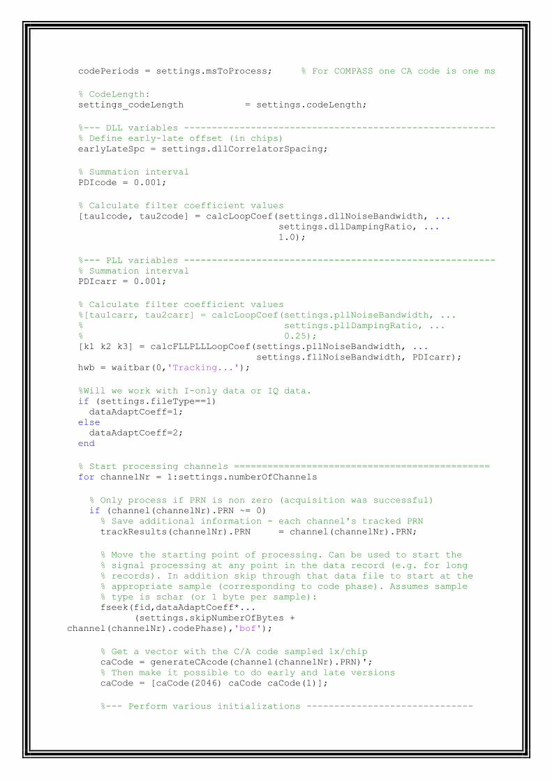
codePeriods = settings.msToProcess; % For COMPASS one CA code is one ms
% CodeLength: settings_codeLength = settings.codeLength;
%--- DLL variables -------------------------------------------------------- % Define early-late offset (in chips) earlyLateSpc = settings.dllCorrelatorSpacing;
% Summation interval PDIcode = 0.001;
% Calculate filter coefficient values [tau1code, tau2code] = calcLoopCoef(settings.dllNoiseBandwidth, ... settings.dllDampingRatio, ... 1.0);
%--- PLL variables -------------------------------------------------------- % Summation interval PDIcarr = 0.001;
% Calculate filter coefficient values %[tau1carr, tau2carr] = calcLoopCoef(settings.pllNoiseBandwidth, ... % settings.pllDampingRatio, ... % 0.25); [k1 k2 k3] = calcFLLPLLLoopCoef(settings.pllNoiseBandwidth, ... settings.fllNoiseBandwidth, PDIcarr); hwb = waitbar(0,'Tracking...');
%Will we work with I-only data or IQ data. if (settings.fileType==1) dataAdaptCoeff=1; else dataAdaptCoeff=2; end
% Start processing channels ============================================== for channelNr = 1:settings.numberOfChannels
% Only process if PRN is non zero (acquisition was successful) if (channel(channelNr).PRN ~= 0) % Save additional information - each channel's tracked PRN trackResults(channelNr).PRN = channel(channelNr).PRN;
% Move the starting point of processing. Can be used to start the % signal processing at any point in the data record (e.g. for long % records). In addition skip through that data file to start at the % appropriate sample (corresponding to code phase). Assumes sample % type is schar (or 1 byte per sample): fseek(fid,dataAdaptCoeff*... (settings.skipNumberOfBytes +
channel(channelNr).codePhase),'bof');
% Get a vector with the C/A code sampled 1x/chip caCode = generateCAcode(channel(channelNr).PRN)'; % Then make it possible to do early and late versions caCode = [caCode(2046) caCode caCode(1)];
%--- Perform various initializations ------------------------------

% define initial code frequency basis of NCO codeFreq = settings.codeFreqBasis; % define residual code phase (in chips) remCodePhase = 0.0; % define carrier frequency which is used over whole tracking period carrFreq = channel(channelNr).acquiredFreq; carrFreqBasis = channel(channelNr).acquiredFreq; % define residual carrier phase remCarrPhase = 0.0;
%code tracking loop parameters oldCodeNco = 0.0; oldCodeError = 0.0;
%carrier/Costas loop parameters oldCarrNco = 0.0; oldCarrError = 0.0;
%frequency lock loop parameters oldFreqNco = 0.0; oldFreqError = 0.0; vsmCnt = 0;CNo = 0; %explain this! I1 = 0.001; I2 = 0.001; Q1 = 0.001; Q2 = 0.001;
%temp variables! We have to use them in order to speed up the code! %Structs are extemly slow in scilab 5.3.0 :( loopCnt_carrFreq = ones(1, settings.msToProcess); loopCnt_codeFreq = ones(1, settings.msToProcess); loopCnt_absoluteSample = zeros(1, settings.msToProcess); loopCnt_dllDiscr = ones(1, settings.msToProcess); loopCnt_dllDiscrFilt = ones(1, settings.msToProcess); loopCnt_pllDiscr = ones(1, settings.msToProcess); loopCnt_pllDiscrFilt = ones(1, settings.msToProcess); loopCnt_I_E = zeros(1, settings.msToProcess); loopCnt_I_P = zeros(1, settings.msToProcess); loopCnt_I_L = zeros(1, settings.msToProcess); loopCnt_Q_E = zeros(1, settings.msToProcess); loopCnt_Q_P = zeros(1, settings.msToProcess); loopCnt_Q_L = zeros(1, settings.msToProcess);
loopCnt_samplingFreq = settings.samplingFreq; loopCnt_codeLength = settings.codeLength; loopCnt_dataType = settings.dataType; loopCnt_codeFreqBasis = settings.codeFreqBasis; loopCnt_numberOfChannels = settings.numberOfChannels
%=== Process the number of specified code periods ================= for loopCnt = 1:codePeriods
%% GUI update --------------------------------------------------------
----- % The GUI is updated every 50ms. This way Matlab GUI is still % responsive enough. At the same time Matlab is not occupied % all the time with GUI task. if (rem(loopCnt, 50) == 0)
Ln=sprintf('\n');
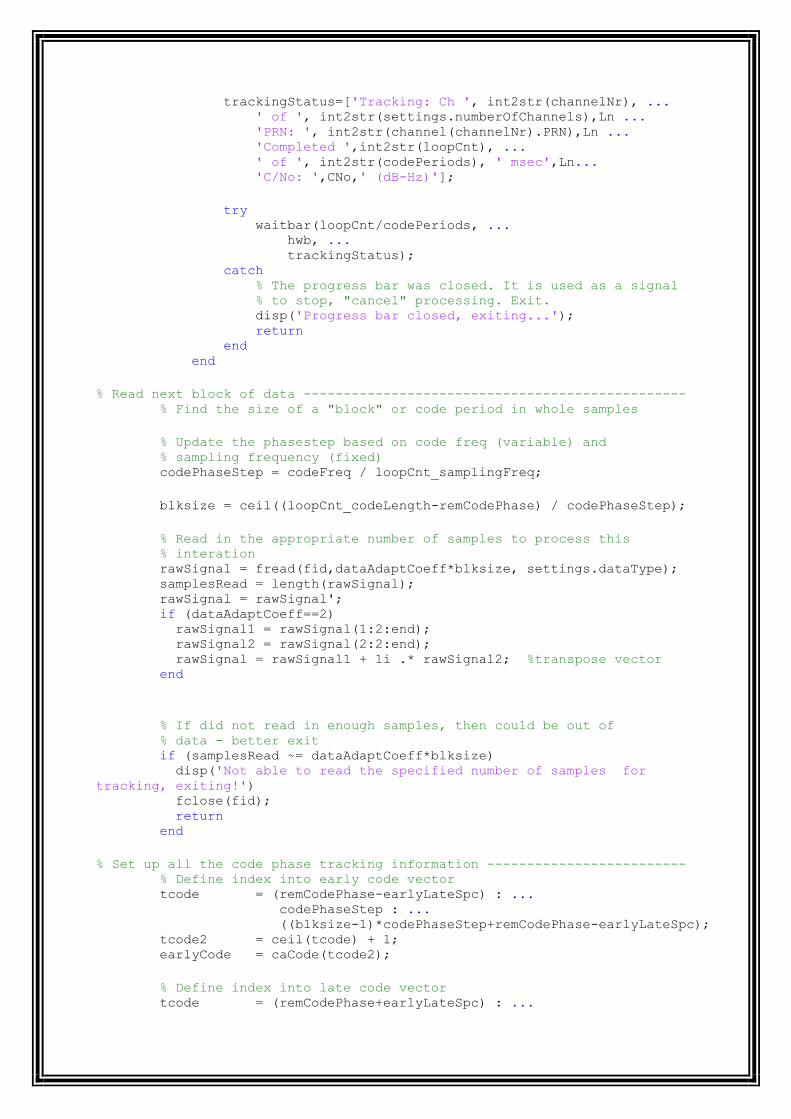
trackingStatus=['Tracking: Ch ', int2str(channelNr), ... ' of ', int2str(settings.numberOfChannels),Ln ... 'PRN: ', int2str(channel(channelNr).PRN),Ln ... 'Completed ',int2str(loopCnt), ... ' of ', int2str(codePeriods), ' msec',Ln... 'C/No: ',CNo,' (dB-Hz)'];
try waitbar(loopCnt/codePeriods, ... hwb, ... trackingStatus); catch % The progress bar was closed. It is used as a signal % to stop, "cancel" processing. Exit. disp('Progress bar closed, exiting...'); return end end
% Read next block of data ------------------------------------------------ % Find the size of a "block" or code period in whole samples
% Update the phasestep based on code freq (variable) and % sampling frequency (fixed) codePhaseStep = codeFreq / loopCnt_samplingFreq;
blksize = ceil((loopCnt_codeLength-remCodePhase) / codePhaseStep);
% Read in the appropriate number of samples to process this % interation rawSignal = fread(fid,dataAdaptCoeff*blksize, settings.dataType); samplesRead = length(rawSignal); rawSignal = rawSignal'; if (dataAdaptCoeff==2) rawSignal1 = rawSignal(1:2:end); rawSignal2 = rawSignal(2:2:end); rawSignal = rawSignal1 + 1i .* rawSignal2; %transpose vector end
% If did not read in enough samples, then could be out of % data - better exit if (samplesRead ~= dataAdaptCoeff*blksize) disp('Not able to read the specified number of samples for
tracking, exiting!') fclose(fid); return end
% Set up all the code phase tracking information ------------------------- % Define index into early code vector tcode = (remCodePhase-earlyLateSpc) : ... codePhaseStep : ... ((blksize-1)*codePhaseStep+remCodePhase-earlyLateSpc); tcode2 = ceil(tcode) + 1; earlyCode = caCode(tcode2);
% Define index into late code vector tcode = (remCodePhase+earlyLateSpc) : ...

codePhaseStep : ... ((blksize-1)*codePhaseStep+remCodePhase+earlyLateSpc); tcode2 = ceil(tcode) + 1; lateCode = caCode(tcode2);
% Define index into prompt code vector tcode = remCodePhase : ... codePhaseStep : ... ((blksize-1)*codePhaseStep+remCodePhase); tcode2 = ceil(tcode) + 1; promptCode = caCode(tcode2);
remCodePhase = (tcode(blksize) + codePhaseStep) - 2046.0;
% Generate the carrier frequency to mix the signal to baseband ----------- time = (0:blksize) ./ loopCnt_samplingFreq;
% Get the argument to sin/cos functions trigarg = ((carrFreq * 2.0 * pi) .* time) + remCarrPhase; remCarrPhase = trigarg(blksize+1)-... fix(trigarg(blksize+1)./(2 * pi)).*(2 * pi);
% Finally compute the signal to mix the collected data to % bandband carrsig = exp(i .* trigarg(1:blksize));
% Generate the six standard accumulated values --------------------------- % First mix to baseband qBasebandSignal = real(carrsig .* rawSignal); iBasebandSignal = imag(carrsig .* rawSignal);
% Now get early, late, and prompt values for each I_E = sum(earlyCode .* iBasebandSignal); Q_E = sum(earlyCode .* qBasebandSignal); I_P = sum(promptCode .* iBasebandSignal); Q_P = sum(promptCode .* qBasebandSignal); I_L = sum(lateCode .* iBasebandSignal); Q_L = sum(lateCode .* qBasebandSignal);
% Find combined PLL/FLL error and update carrier NCO (FLL-assisted PLL) -----
- I2 = I1; Q2 = Q1; I1 = I_P; Q1 = Q_P;
if (sign(I2)~=sign(I1)) I2 = -I2; Q2 = -Q2; end
cross = I1*Q2 - I2*Q1; dot = abs(I1*I2 + Q1*Q2); %/ This is potentially bug. %/ In theory there is no abs()! %/ dot = abs(I1*I2 + Q1*Q2); %/ But it works :)
% Implement carrier loop discriminator (frequency detector) %freqError = atan(cross, dot)/(2*%pi)/0.001/500; %0.001 - integration
periode. 500 - maximum discriminator output.

freqError = atan(cross/dot) / pi; %normalized output in the range
from -1 to +1.
% Implement carrier loop discriminator (phase detector) carrError = atan(Q_P / I_P) / (2.0 * pi);
%Implement carrier loop filter and generate NCO command; carrNco = oldCarrNco + k1*carrError - k2*oldCarrError - k3*freqError;
oldCarrNco = carrNco; oldCarrError = carrError;
carrFreq = carrFreqBasis + carrNco;
loopCnt_carrFreq(loopCnt) = carrFreq;
% Find DLL error and update code NCO ------------------------------------- codeError = (sqrt(I_E * I_E + Q_E * Q_E) - ... sqrt(I_L * I_L + Q_L * Q_L)) / ... (sqrt(I_E * I_E + Q_E * Q_E) +... sqrt(I_L * I_L + Q_L * Q_L));
% Implement code loop filter and generate NCO command codeNco = oldCodeNco + (tau2code/tau1code) * ... (codeError - oldCodeError) + codeError *
(PDIcode/tau1code); oldCodeNco = codeNco; oldCodeError = codeError;
% Modify code freq based on NCO command codeFreq = loopCnt_codeFreqBasis - codeNco + ( (carrFreq -
settings.IF)/763 );
loopCnt_codeFreq(loopCnt) = codeFreq;
% Record various measures to show in postprocessing ---------------------- % Record sample number (based on 8bit samples) loopCnt_absoluteSample(loopCnt) =(ftell(fid))/dataAdaptCoeff - ... remCodePhase * ...
(loopCnt_samplingFreq/1000)/settings_codeLength;
loopCnt_dllDiscr(loopCnt) = codeError; loopCnt_dllDiscrFilt(loopCnt) = codeNco; loopCnt_pllDiscr(loopCnt) = carrError; loopCnt_pllDiscrFilt(loopCnt) = carrNco;
loopCnt_I_E(loopCnt) = I_E; loopCnt_I_P(loopCnt) = I_P; loopCnt_I_L(loopCnt) = I_L; loopCnt_Q_E(loopCnt) = Q_E; loopCnt_Q_P(loopCnt) = Q_P; loopCnt_Q_L(loopCnt) = Q_L; end % for loopCnt
% If we got so far, this means that the tracking was successful % Now we only copy status, but it can be update by a lock detector % if implemented trackResults(channelNr).status = channel(channelNr).status;

%Now copy all data from temp variable to the real place! %We do it to speed up the code. trackResults(channelNr).carrFreq = loopCnt_carrFreq; trackResults(channelNr).codeFreq = loopCnt_codeFreq; trackResults(channelNr).absoluteSample = loopCnt_absoluteSample; trackResults(channelNr).dllDiscr = loopCnt_dllDiscr; trackResults(channelNr).dllDiscrFilt = loopCnt_dllDiscrFilt; trackResults(channelNr).pllDiscr = loopCnt_pllDiscr; trackResults(channelNr).pllDiscrFilt = loopCnt_pllDiscrFilt; trackResults(channelNr).I_E = loopCnt_I_E; trackResults(channelNr).I_P = loopCnt_I_P; trackResults(channelNr).I_L = loopCnt_I_L; trackResults(channelNr).Q_E = loopCnt_Q_E; trackResults(channelNr).Q_P = loopCnt_Q_P; trackResults(channelNr).Q_L = loopCnt_Q_L;
end % if a PRN is assigned end % for channelNr
% Close the waitbar close(hwb)
4. PostNavigation function [navSolutions, eph,SOW,satPositions,
satClkCorr,navSol_channel_rawP,subFrameStart,activeChnList,nav_bits] =
postNavigation(trackResults, settings) %Function calculates navigation solutions for the receiver (pseudoranges, %positions). At the end it converts coordinates from the WGS84 system to %the UTM, geocentric or any additional coordinate system. % %[navSolutions, eph] = postNavigation(trackResults, settings) % % Inputs: % trackResults - results from the tracking function (structure % array). % settings - receiver settings. % Outputs: % navSolutions - contains measured pseudoranges, receiver % clock error, receiver coordinates in several % coordinate systems (at least ECEF and UTM). % eph - received ephemerides of all SV (structure array).
%--------------------------------------------------------------------------
% Check is there enough data to obtain any navigation solution ===========
%Local variables (to speed up code, bacause working with structs is slow): trkRslt_I_P = zeros(size(trackResults, 2), (settings.msToProcess -
settings.skipNumberOfFirstBits)); trkRslt_PRN = zeros(size(trackResults, 2)); %% Changed by JAY %% for i = 1:size(trackResults,2)

trkRslt_I_P(i,:) =
trackResults(i).I_P((settings.skipNumberOfFirstBits+1):end); %trkRslt_PRN(i) = trackResults(i).PRN; absoluteSample(i,:) =
trackResults(i).absoluteSample((settings.skipNumberOfFirstBits+1):end); end
%for i = 1:size(trackResults, 2)
% absoluteSample(i,:) = trackResults(i).absoluteSample; %end
set_numberOfChnls = settings.numberOfChannels; set_c = settings.c; set_navSolPeriod = settings.navSolPeriod; set_elevationMask = settings.elevationMask; set_useTropCorr = settings.useTropCorr; set_samplesPerCode = round(settings.samplingFreq / ... (settings.codeFreqBasis /
settings.codeLength)); set_dataTypeSizeInBytes = settings.dataTypeSizeInBytes; %Local variables - end.
false = sum([trackResults.status] ~= '-');
if (settings.msToProcess < 39000) || (false < 4) Show the error message and exit printf('Record is too short or too few satellites tracked. Exiting!\n'); navSolutions = []; eph = []; return end
% Find time marks start positions
========================================== [subFrameStart, activeChnList,nav_bits] =... findSubframeStart(trackResults,trkRslt_I_P,settings); %pause;
%% checked for all right 16/4/2013
%%
%% % Decode ephemerides ===================================================== for channelNr = activeChnList channelNr; %Add condition for the case of weak signal (Not all nav data is
available): delFromActiveChnList = []; %% Changed BY JAY 4/15/2013
%if (subFrameStart(channelNr) + (30000) -1) >
length(trackResults(channelNr).I_P(channelNr,:))

% delFromActiveChnList = [delFromActiveChnList channelNr]; %activeChnList = setdiff(activeChnList, channelNr); %stringStart(channelNr) = [] %continue; %else %--- Copy 5 subframes long record from tracking output --------------- %navBitsSamples = trackResults(channelNr).I_P(subFrameStart(channelNr)
: ... % subFrameStart(channelNr) + (30000) -1)'; navBitsSamples = trkRslt_I_P(channelNr, subFrameStart(channelNr) : ... subFrameStart(channelNr) + (30000) -1)';
%--- Convert prompt correlator output to +-1 --------- navBitsSamples = sign(navBitsSamples'); %--- Decode data and extract ephemeris information --- [eph(trackResults(channelNr).PRN), SOW(trackResults(channelNr).PRN)] =
ephemeris(navBitsSamples);
%--- Exclude satellite if it does not have the necessary nav data ----- % we will check existence of at least one variable from each % navigation string. It would be better to check existence of all
variable % but in this case the condition will be too huge and unclear! if (isempty(eph(trackResults(channelNr).PRN).IODC) || ... isempty(eph(trackResults(channelNr).PRN).M_0) || ... isempty(eph(trackResults(channelNr).PRN).i_0) );
%--- Exclude channel from the list (from further processing) ------ %activeChnList = setdiff(activeChnList, channelNr); delFromActiveChnList = [delFromActiveChnList channelNr]; end
%--- Exclude satellite if it has MSB of health flag set: if ( eph(trackResults(channelNr).PRN).SatH1 == 1 ) %activeChnList = setdiff(activeChnList, channelNr); %/delFromActiveChnList = [delFromActiveChnList channelNr];%temporary
disable... end end %end %pause; %/activeChnList(delFromActiveChnList) = [];%temporary disable %/subFrameStart(delFromActiveChnList) = [];%temporary disable
% Check if the number of satellites is still above 3 ===================== if (isempty(activeChnList) || (size(activeChnList, 2) < 4)) % Show error message and exit printf('Too few satellites with ephemeris data for postion calculations.
Exiting!\n'); navSolutions = []; eph = []; return end
% Initialization =========================================================
% Set the satellite elevations array to INF to include all satellites for % the first calculation of receiver position. There is no reference point % to find the elevation angle as there is no receiver position estimate at % this point.

satElev = inf*ones(1, set_numberOfChnls);
% Save the active channel list. The list contains satellites that are % tracked and have the required ephemeris data. In the next step the list % will depend on each satellite's elevation angle, which will change over % time. readyChnList = activeChnList;
transmitTime = SOW; %pause; %########################################################################## %# Do the satellite and receiver position calculations # %##########################################################################
% Initialization of current measurement ================================== for currMeasNr = 1:fix((settings.msToProcess - max(subFrameStart) -... settings.skipNumberOfFirstBits) / ... set_navSolPeriod) % Exclude satellites, that are belove elevation mask %/activeChnList = intersect(find(satElev >= set_elevationMask), ... %/ readyChnList);
% Save list of satellites used for position calculation navSol_channel_SVN(activeChnList, currMeasNr) =
trackResults(activeChnList).PRN;
% These two lines help the skyPlot function. The satellites excluded % to do elevation mask will not "jump" to possition (0,0) in the sky % plot. navSol_channel_el(:, currMeasNr) = nan*ones(set_numberOfChnls, 1); navSol_channel_az(:, currMeasNr) = nan*ones(set_numberOfChnls, 1);
% Find pseudoranges
====================================================== navSol_channel_rawP(:, currMeasNr) = calculatePseudoranges(... set_numberOfChnls, set_samplesPerCode, absoluteSample,... set_c, set_dataTypeSizeInBytes, ... subFrameStart + set_navSolPeriod * (currMeasNr-1),
activeChnList)';
% Find satellites positions and clocks corrections
======================= [satPositions, satClkCorr] = satpos(transmitTime, ... [trackResults(activeChnList).PRN],
... eph, settings); currMeasNr %pause; % Find receiver position
=================================================
% 3D receiver position can be found only if signals from more than 3 % satellites are available if length(activeChnList) > 3
%=== Calculate receiver position ================================== [xyzdt sat_el sat_az sat_dop] = leastSquarePos(satPositions, ... navSol_channel_rawP(activeChnList, currMeasNr)' -
...

satClkCorr * set_c, ... set_c, set_useTropCorr); navSol_channel_el(activeChnList, currMeasNr) = sat_el'; navSol_channel_az(activeChnList, currMeasNr) = sat_az'; navSol_DOP(:, currMeasNr) = sat_dop'; % %Transform from PZ90.02 to WGS84! % xyz = xyzdt(1:3); % xyz = [-1.1 -0.3 -0.9] + (1-0.12e-6).*([1 -0.82e-6 0; 0.82e-6 1 0; 0
0 1] * xyz')'; % xyzdt(1:3) = xyz; % % navSol_channel_el(activeChnList, currMeasNr) = sat_el'; % navSol_channel_az(activeChnList, currMeasNr) = sat_az'; % navSol_DOP(:, currMeasNr) = sat_dop';
%--- Save results ------------------------------------------------- navSol_X(currMeasNr) = xyzdt(1); navSol_Y(currMeasNr) = xyzdt(2); navSol_Z(currMeasNr) = xyzdt(3); navSol_dt(currMeasNr) = xyzdt(4);
% Update the satellites elevations vector satElev = navSol_channel_el(:, currMeasNr);
%=== Correct pseudorange measurements for clocks errors =========== navSol_channel_corrP(activeChnList, currMeasNr) = ... navSol_channel_rawP(activeChnList, currMeasNr) - ... satClkCorr' * set_c + navSol_dt(currMeasNr);
% Coordinate conversion
==================================================
%=== Convert to geodetic coordinates ============================== [navSol_latitude(currMeasNr), ... navSol_longitude(currMeasNr), ... navSol_height(currMeasNr)] = cart2geo(... navSol_X(currMeasNr), ... navSol_Y(currMeasNr), ... navSol_Z(currMeasNr), ... 5);
%=== Convert to UTM coordinate system ============================= navSol_UtmZone = findUtmZone(navSol_latitude(currMeasNr), ... navSol_longitude(currMeasNr));
[navSol_E(currMeasNr), ... navSol_N(currMeasNr), ... navSol_U(currMeasNr)] = cart2utm(xyzdt(1), xyzdt(2), ... xyzdt(3), ... navSol_UtmZone);
else % if size(activeChnList, 2) > 3 %--- There are not enough satellites to find 3D position ---------- %/disp([' Measurement No. ', num2str(currMeasNr), ... %/ ': Not enough information for position solution.']);
%--- Set the missing solutions to NaN. These results will be %excluded automatically in all plots. For DOP it is easier to use %zeros. NaN values might need to be excluded from results in some

%of further processing to obtain correct results. navSol_X(currMeasNr) = nan; navSol_Y(currMeasNr) = nan; navSol_Z(currMeasNr) = nan; navSol_dt(currMeasNr) = nan; navSol_DOP(:, currMeasNr) = zeros(5, 1); navSol_latitude(currMeasNr) = nan; navSol_longitude(currMeasNr) = nan; navSol_height(currMeasNr) = nan; navSol_E(currMeasNr) = nan; navSol_N(currMeasNr) = nan; navSol_U(currMeasNr) = nan;
navSol_channel_az(activeChnList, currMeasNr) =
nan*ones(length(activeChnList),1); navSol_channel_el(activeChnList, currMeasNr) =
nan*ones(length(activeChnList),1);
% TODO: Know issue. Satellite positions are not updated if the % satellites are excluded do to elevation mask. Therefore raising % satellites will be not included even if they will be above % elevation mask at some point. This would be a good place to % update positions of the excluded satellites.
end % if size(activeChnList, 2) > 3
%=== Update the transmit time ("measurement time") ==================== transmitTime = transmitTime + set_navSolPeriod / 1000;
end %for currMeasNr...
%Some trciks to speed up code. Structs are VERY SLOW in scilab 5.3.0. navSolutions.X = navSol_X; navSolutions.Y = navSol_Y; navSolutions.Z = navSol_Z; navSolutions.dt = navSol_dt; navSolutions.latitude = navSol_latitude; navSolutions.longitude = navSol_longitude; navSolutions.height = navSol_height; navSolutions.utmZone = navSol_UtmZone; navSolutions.E = navSol_E; navSolutions.N = navSol_N; navSolutions.U = navSol_U; navSolutions.DOP = navSol_DOP; navSolutions.channel.SVN = navSol_channel_SVN; navSolutions.channel.el = navSol_channel_el; navSolutions.channel.az = navSol_channel_az; navSolutions.channel.rawP = navSol_channel_rawP; navSolutions.channel.correctedP = navSol_channel_corrP;
%