Development of Intelligence Automated Robotic Arm Workstation
6
Development of Intelligence Automated Robotic Arm Workstation Chia-Ying Hsieh, Ying-Jie Jhao, Chen-Huan Chang, and Lin-Yin Chen Department Automation Engineering, National Formosa University, Yunlin, Taiwan E-mail: [email protected], [email protected], {harry850819, lovejp6m6}@gmail.com, [email protected] Jeng-Dao Lee 1,2 1 Department of Automation Engineering, National Formosa University. Yunlin, Taiwan 2 Smart Machine and Intelligent Manufacturing Research Center, National Formosa University, Huwei, Yunlin, Taiwan E-mail: [email protected] Abstract—According to industry 4.0 development, many fields not only factories but companies are achieving the goal of intelligence production and going to be transforming to promote their competition. In this paper, we achieved the target of using Internet of things (IOT) in our workstation. It concludes the structure of IOT module, product resume, AOI system, webpage, monitoring module and database. Using IOT module to receive the data from workstation, and then the AOI system detected the products of the defacement and identity of the product. The experiment result is stored in the database and showed on the webpage. All the situation of the workstation’s data can be monitored via the monitoring webpage by the users. The progress of the research is that workers could leave the dangerous circumstance and remote via computer to monitor the working process. Index Terms—IOT module, product resume, AOI system, webpage, monitoring module, database I. INTRODUCTION In recent year, automation field [1] emerged and become more popular than the past. Many of the factories improve the conventional system into intelligent one. Therefore, robot is one of the point in industry. Because of the trend, robot industry was more popular. The factory import industry4.0 [2] with big data, database and AI applications. The goal which is upgrading the process line is for the smart factory [3-4]. In this paper, IOT module is used to develop the issue of promoting the processing. It based on automation workstation and then upgrading into industry4.0 which is included database, and monitoring web page. The structures are using RFID, robotic arm and database that is SQL system [5] and establishing the server that Apache remote monitoring webpage on the platform system [6]. It separates into manager and users. Manager could control the products and data via webpage and operate the machine in remote condition. Manuscript received March 21, 2019; revised April 1, 2020. II. SYATEM STRUCTURE OF WORKSTATION Robot field is popular in automation industry. the market application of global robots is major in industrial robot. Thus, developing intelligent robot industry is an important part of industrial intellectualization with features of digitization, intellectualization and networking. This means that the development of robots not only replaces manual labor but also replaces mental labor[7]. Take FANUC [8] and ABB [9] for example. FANUC robotic arm was used on Nissan’s producing line and it is used for assembling. On the other hand, ABB robotic arm is used for analysis [10]. In this paper, the automation workstation is used FANUC robotic arm. It is common in industry to used robotic arm in producing line. Therefore, the module that was increased is transformed into smart factory. The system structure was illustrated in Fig. 1. It included seven different parts that are database, PC, webcam, IOT module, webpage, product resume and robot automation workstation. The individual parts are explained as follows: A. IOT Module It was consist by Raspberry Pi [11], MCP3008, temperate sensor, air pressure sensor and photo resistance. It was received the data and calculated. B. Product Resume The product resume was made up of PC, laser scanner and product. The laser scanner was scanned the barcode of the product and used USB protocol to PC. C. Web It was established via Laravel [12] frame and PHP language. It used graphical interface and format to show the relation data. D. Monitoring Module It was used Webcam, Logitech C910, for monitoring the multi-function electric meter and deal with AOI via OpenCV [13]. 679 International Journal of Mechanical Engineering and Robotics Research Vol. 9, No. 5, May 2020 © 2020 Int. J. Mech. Eng. Rob. Res doi: 10.18178/ijmerr.9.5.679-684
Transcript of Development of Intelligence Automated Robotic Arm Workstation

Development of Intelligence Automated Robotic
Arm Workstation
Chia-Ying Hsieh, Ying-Jie Jhao, Chen-Huan Chang, and Lin-Yin Chen Department Automation Engineering, National Formosa University, Yunlin, Taiwan
E-mail: [email protected], [email protected], {harry850819, lovejp6m6}@gmail.com,
Jeng-Dao Lee1,2
1 Department of Automation Engineering, National Formosa University. Yunlin, Taiwan
2Smart Machine and Intelligent Manufacturing Research Center, National Formosa University, Huwei, Yunlin, Taiwan
E-mail: [email protected]
Abstract—According to industry 4.0 development, many
fields not only factories but companies are achieving the
goal of intelligence production and going to be transforming
to promote their competition. In this paper, we achieved the
target of using Internet of things (IOT) in our workstation.
It concludes the structure of IOT module, product resume,
AOI system, webpage, monitoring module and database.
Using IOT module to receive the data from workstation,
and then the AOI system detected the products of the
defacement and identity of the product. The experiment
result is stored in the database and showed on the webpage.
All the situation of the workstation’s data can be monitored
via the monitoring webpage by the users. The progress of
the research is that workers could leave the dangerous
circumstance and remote via computer to monitor the
working process.
Index Terms—IOT module, product resume, AOI system,
webpage, monitoring module, database
I. INTRODUCTION
In recent year, automation field [1] emerged and
become more popular than the past. Many of the
factories improve the conventional system into intelligent
one. Therefore, robot is one of the point in industry.
Because of the trend, robot industry was more popular.
The factory import industry4.0 [2] with big data,
database and AI applications. The goal which is
upgrading the process line is for the smart factory [3-4].
In this paper, IOT module is used to develop the issue of
promoting the processing. It based on automation
workstation and then upgrading into industry4.0 which is
included database, and monitoring web page. The
structures are using RFID, robotic arm and database that
is SQL system [5] and establishing the server that
Apache remote monitoring webpage on the platform
system [6]. It separates into manager and users. Manager
could control the products and data via webpage and
operate the machine in remote condition.
Manuscript received March 21, 2019; revised April 1, 2020.
II. SYATEM STRUCTURE OF WORKSTATION
Robot field is popular in automation industry. the
market application of global robots is major in industrial
robot. Thus, developing intelligent robot industry is an
important part of industrial intellectualization with
features of digitization, intellectualization and networking.
This means that the development of robots not only
replaces manual labor but also replaces mental labor[7].
Take FANUC [8] and ABB [9] for example. FANUC
robotic arm was used on Nissan’s producing line and it is
used for assembling. On the other hand, ABB robotic
arm is used for analysis [10]. In this paper, the
automation workstation is used FANUC robotic arm. It is
common in industry to used robotic arm in producing
line. Therefore, the module that was increased is
transformed into smart factory.
The system structure was illustrated in Fig. 1. It
included seven different parts that are database, PC,
webcam, IOT module, webpage, product resume and
robot automation workstation. The individual parts are
explained as follows:
A. IOT Module
It was consist by Raspberry Pi [11], MCP3008,
temperate sensor, air pressure sensor and photo
resistance. It was received the data and calculated.
B. Product Resume
The product resume was made up of PC, laser scanner
and product. The laser scanner was scanned the barcode
of the product and used USB protocol to PC.
C. Web
It was established via Laravel [12] frame and PHP
language. It used graphical interface and format to show
the relation data.
D. Monitoring Module
It was used Webcam, Logitech C910, for monitoring
the multi-function electric meter and deal with AOI via
OpenCV [13].
679
International Journal of Mechanical Engineering and Robotics Research Vol. 9, No. 5, May 2020
© 2020 Int. J. Mech. Eng. Rob. Resdoi: 10.18178/ijmerr.9.5.679-684

E. Database
The database was used MySQL to storage the data.
This was read from four different sensors via SPI
interface.
Figure 1. System structure of workstation.
The devices are receiving an order by PC controller.
The holding-device was made by vacuum chuck and
pneumatic jaw. Using vacuum generator to create
negative air pressure for vacuum chuck and solenoid
valve controlled pneumatic jaw. Ring lights and camera
used in AOI (Automated Optical Inspection) station.
Especially the camera, it connected the controller of
robotic arm via Camera Link and then cooperated with
ring lights. The level of illumination was the best than
others to capture. The web was showed the data which
was captured from database for users. The database was
communicated with PC via WIFI. It used MySQL to be
our database. It storage the value which was came from
product resume, IOT and monitoring module.
III. EXPERIMENTAL RESULTS
Figure 2. The plot plan of workstation.
The experimental workstation in this study is depicted
in Fig. 2. According to the workstation, it illustrated the
routine and the application of six axis robotic arm. The
station divided into various parts that are storage,
checking, AOI, gluing and assembling. Especially the
application of air pressure gluing machine, industrial
camera and the elements of air pressure, these appeared
the entirely automation workstation with detection and
gluing active.
This was produced a wooden mirror which showing in
Fig. 3. The component of the frame was self-producing
with shape of square. The sizes of square element are lens
are 95mm×95mm and 78mm×78mm, respectively. It is
launched at the green space that is the storage station and
end at red space called palletize.
Figure 3. Product material.
The flow chart of workstation is illustrated in Fig. 4.
For first, it went on initialization. The robotic arm moved
to storage station and sucked the object from feed tray.
After that, it went on recognizing at AOI station. In this
station, defacement objects will move on defect product
station and abandon. Before abandoning, there is a
barcode on objects. The camera recognized the barcode
and checked. In assembling station, it was made the
object at a fix point. At the same time, robotic arm went
back feeder station to suck the lens and put into
second-position station.
Then moving to gluing station, the arm moved via the
path which we set in program and started the air
compressor. In the end, robotic arm went on assembling
station to combine the lens and frames and then grabbed
the finished good to place into palletize. The process can
always be repeated.
Figure 4. The flow chart of workstation.
A. IOT Application Module
The structure of IOT module is illustrated in Fig. 5.
Using Raspberry Pi to be a controller and collect the
analog signal by MCP3008 to develop a low cost IOT
module. After acquiring the signal, it transmits into
Controller
PC
Ethernet
WIFI
Factory light
Air pressure sensorTemperate sensorRaspberry Pi
A5 Database
SPI
Web
Photo resistanceMCP3008
Analog signal
Webcam
A1 IOT module
A4 Monitoring module
A2 Product resume
PC
Laser scannerproduct
USB
scanning
WIFI
WIFI
Ethernet
Ethernet
A3
Robot automation workstation
1 feeder station2 AOI station
3 gluing station
5 assembling station6 palletize 4 defective station
start
Workstation
initial
Pick the wooden
square frame
Image recognize
of one
dimensional
barcode
Defective
detection
Place into
assembling
station
Place into
defective station
Pick the square
type mirror
Lens secondary
and gluing
Combining at
assembling
station
Pick the finish
product into
palletize
OK
NG
680
International Journal of Mechanical Engineering and Robotics Research Vol. 9, No. 5, May 2020
© 2020 Int. J. Mech. Eng. Rob. Res

Raspberry Pi by the type of Serial Peripheral Interface. It
went on initial calculation when Raspberry Pi receiving
the data. This will store in the MySQL database via WIFI
transmission module which connect the same film router.
Figure 5. IOT module structure.
The IOT module flow chart is shown in Fig. 6. When
the program beginning, it loaded the library and
connected the MySQL database to check the value. This
is for the feedback of four different sensors. After that,
the program will not only launch transformation of data
to physical value but judging equipment’s condition. In
the end, the value will be uploaded to database and
stored in the instruction form. Logging out the database
to ensure the uploading data should be all connected.
After 5 seconds, it will restart the program.
Figure 6. IOT module flow chart.
1) Result of IOT module data
Figure 7. IOT module program.
The circumstance detail and the situation of equipment
are showed on the interface by IOT module program in
Fig. 7. It was exploited by Raspberry Pi, ADC chip and
various sensors. Raspberry Pi gathered the data statue of
eight different addresses in MCP3008 via SPI interface.
For now, we only used 1 to 4 data address in MCP3008
which was marked in red square to calculate the physical
value by transferring senor’s formula. The orange square
is the practical values which were transferred after
calculation. At the end, it had been uploaded into
MySQL database through API.
The collecting information from IOT module can be
listed in Table I. The data were used to deal with analyze
via every control system of workstation. The main
purpose of data collecting is to make the system be
superior and judging the condition such as, pressure and
temperature etc.
TABLE I. LIST OF DATA COLLECTION
Name Output Function
Pressure Bar
Collecting the air pressure value from workstation
Temperature ℃
Collecting the temperate
value from electric cabinet
Vision_light 0 : error
1 : normal
Collecting the light value
from AOI station
Room_light 0 : people-no
1 : people-yes
Collecting the light value
from factory field
B. AOI System
In this paper, it is presented image identification
system structure in Fig. 8. The detecting area included
barcode scanning and defect detecting with vision
inspection function. In order to remove the defacement
that use to ensure by quality control. In the image
processing flow, determining the object’s exterior and
choosing not only the appropriate camera but lighting
way to stabilize the light. The material’s picture was
grabbed by camera and via the Camera Link. After
dealing with visualization, the value transformed to the
controller of robotic arm. Through the PC captured and
send the value to database, the identification result
showed on the Web page.
Figure 8. AOI system structure.
The flow chart of OpenCV dealing with image is
depicted in Fig. 9. The procedure include four steps,
reading training data, capture and crop the image, image
process and k-NN(k-Nearest Neighbors) algorithm. First,
loading the trained sample to process the calculation via
K-Nearest Neighbors algorithm from OpenCV. The
sample is included capital vocabularies and numbers.
Then, capturing the images to deal with the program in
Raspberry Pi by Webcam. The resolution of image is
640(H)*480(V) and using ROI tool to crop the value of
power meter that could make smoothly on the process.
Then, the images are going to deal with transforming.
The first step of the procedure is put the image into gray
Factory light
GL5528 photo resistance
Ring light with AOI Controller of robotic arm
LM35 temperate sensor
Pneumatic supply
ABPLLNT010BGAA5
air pressure sensor
MCP3008Raspberry PiDatabase
Analog signalSPIWIFI
GL5528 photo resistance
Initial
programmingStart
Read the data
from SPI
interface
Transfer the
data into
physical value
Connect to
database
Wait 5 SEC
Judgmental the
using condition
Uploading the
data into form
Logout the
database
PCCCD Controller of robotic arm Web
EthernetCamera Link
iPendant
681
International Journal of Mechanical Engineering and Robotics Research Vol. 9, No. 5, May 2020
© 2020 Int. J. Mech. Eng. Rob. Res
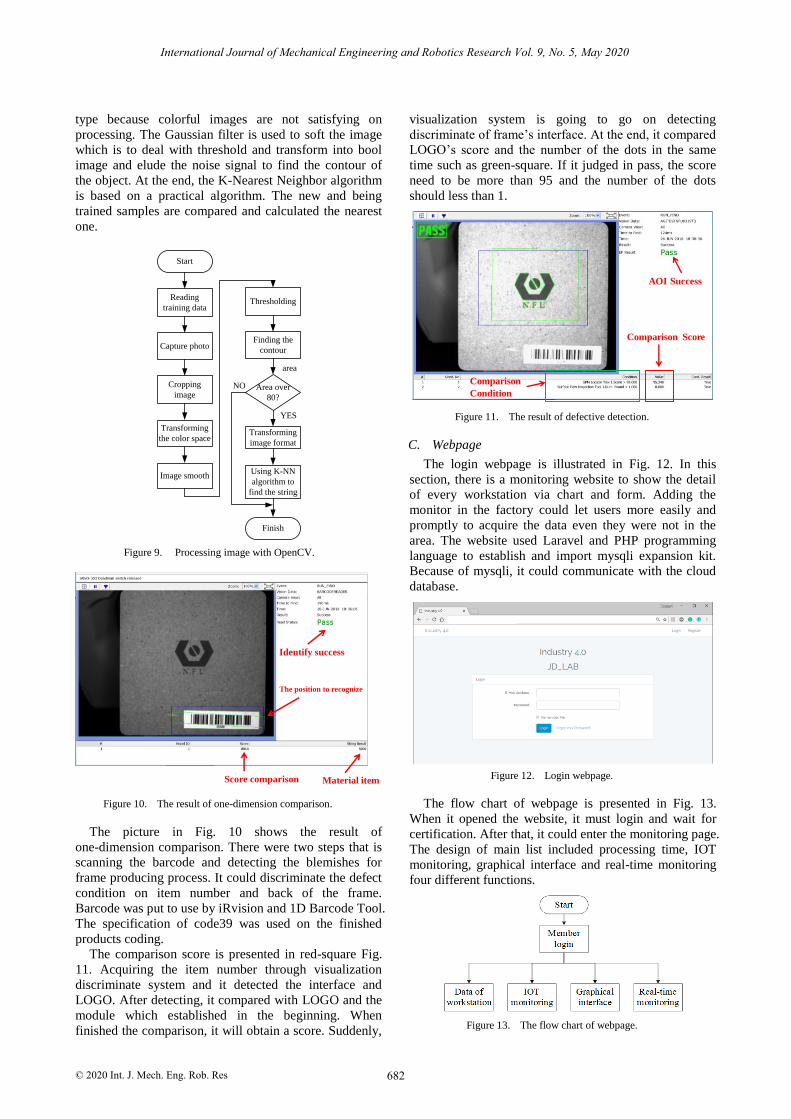
type because colorful images are not satisfying on
processing. The Gaussian filter is used to soft the image
which is to deal with threshold and transform into bool
image and elude the noise signal to find the contour of
the object. At the end, the K-Nearest Neighbor algorithm
is based on a practical algorithm. The new and being
trained samples are compared and calculated the nearest
one.
Figure 9. Processing image with OpenCV.
Figure 10. The result of one-dimension comparison.
The picture in Fig. 10 shows the result of
one-dimension comparison. There were two steps that is
scanning the barcode and detecting the blemishes for
frame producing process. It could discriminate the defect
condition on item number and back of the frame.
Barcode was put to use by iRvision and 1D Barcode Tool.
The specification of code39 was used on the finished
products coding.
The comparison score is presented in red-square Fig.
11. Acquiring the item number through visualization
discriminate system and it detected the interface and
LOGO. After detecting, it compared with LOGO and the
module which established in the beginning. When
finished the comparison, it will obtain a score. Suddenly,
visualization system is going to go on detecting
discriminate of frame’s interface. At the end, it compared
LOGO’s score and the number of the dots in the same
time such as green-square. If it judged in pass, the score
need to be more than 95 and the number of the dots
should less than 1.
Figure 11. The result of defective detection.
C. Webpage
The login webpage is illustrated in Fig. 12. In this
section, there is a monitoring website to show the detail
of every workstation via chart and form. Adding the
monitor in the factory could let users more easily and
promptly to acquire the data even they were not in the
area. The website used Laravel and PHP programming
language to establish and import mysqli expansion kit.
Because of mysqli, it could communicate with the cloud
database.
Figure 12. Login webpage.
The flow chart of webpage is presented in Fig. 13.
When it opened the website, it must login and wait for
certification. After that, it could enter the monitoring page.
The design of main list included processing time, IOT
monitoring, graphical interface and real-time monitoring
four different functions.
Figure 13. The flow chart of webpage.
Start
Reading
training data
Capture photo
Cropping
image
Transforming
the color space
Image smooth
Thresholding
Finding the
contour
Area over
80?
Transforming
image format
Using K-NN
algorithm to
find the string
Finish
YES
NO
area
Score comparison Material item
Identify success
The position to recognize
Comparison Score
Comparison
Condition
AOI Success
682
International Journal of Mechanical Engineering and Robotics Research Vol. 9, No. 5, May 2020
© 2020 Int. J. Mech. Eng. Rob. Res

1) Data of workstation
The webpage shows the receiving data from FAUNC
PC interface in Fig. 14. The data included item number,
time consuming, total time and utilization.
(a)
(b)
Figure 14. Data of workstation.
2) IOT monitoring
The collecting data is showed on the page via IOT
module in Fig. 15. This page could do monitor and see
the data that collected by IOT module at the same time. It
presented the value of air pressure, the temperature of
robot controlling, light in detection area and factory
using condition.
Figure 15. IOT monitoring.
3) Graphical interface
The picture shows the air pressure line chart in Fig. 16.
The data is collected by the senor of the vacuum chuck
on the robotic arm. It is combined in every different
period and showed into line graph.
Figure 16. Graphical interface.
4) Real-time monitoring
The picture from monitor camera could control the
direction and zoom in and out in Fig. 17. The user could
select the different images through the direction bottom.
Figure 17. Real-time monitoring.
IV. CONCLUSION
Many of factories are in transforming steps due to
industry 4.0. The promotion and transformation is
extremely significant. This study is based on IOT
conception and presented a solution of upgrading
traditional industry. We not only designed but produced
a workstation which could glue and assemble by FAUNC
six axis robotic arms. Using visualization system
detected quality on raw materials and abandoned
defective objects into failure station. At the same time,
the identification of product will be read and record the
values to the database when the system working. In the
end, the goods will be made in traceability. People who
work in factory could use bar code machine to scan
product’s one-dimensional bar code for searching
production-inform. In the future, the IOT module will be
established in a variety of working task and upgrading the
programs such as the analyzing of the data or predicting
the problems.
CONFLICT OF INTEREST
The authors declare no conflict of interest.
683
International Journal of Mechanical Engineering and Robotics Research Vol. 9, No. 5, May 2020
© 2020 Int. J. Mech. Eng. Rob. Res
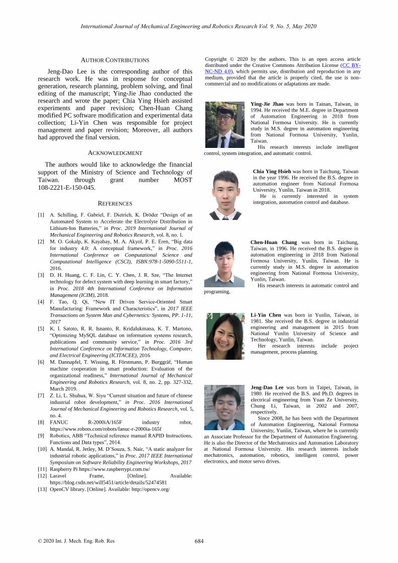
AUTHOR CONTRIBUTIONS
Jeng-Dao Lee is the corresponding author of this research work. He was in response for conceptual generation, research planning, problem solving, and final editing of the manuscript; Ying-Jie Jhao conducted the research and wrote the paper; Chia Ying Hsieh assisted experiments and paper revision; Chen-Huan Chang modified PC software modification and experimental data collection; Li-Yin Chen was responsible for project management and paper revision; Moreover, all authors had approved the final version.
ACKNOWLEDGMENT
The authors would like to acknowledge the financial
support of the Ministry of Science and Technology of
Taiwan. through grant number MOST
108-2221-E-150-045.
REFERENCES
[1] A. Schilling, F. Gabriel, F. Dietrich, K. Dröder “Design of an
Automated System to Accelerate the Electrolyte Distribution in
Lithium-Ion Batteries,” in Proc. 2019 International Journal of
Mechanical Engineering and Robotics Research, vol. 8, no. 1.
[2] M. O. Gokalp, K. Kayabay, M. A. Akyol, P. E. Eren, “Big data
for industry 4.0: A conceptual framework,” in Proc. 2016
International Conference on Computational Science and
Computational Intelligence (CSCI), ISBN:978-1-5090-5511-1,
2016.
[3] D. H. Huang, C. F. Lin, C. Y. Chen, J. R. Sze, “The Internet
technology for defect system with deep learning in smart factory,”
in Proc. 2018 4th International Conference on Information
Management (ICIM), 2018.
[4] F. Tao, Q. Qi, “New IT Driven Service-Oriented Smart
Manufacturing: Framework and Characteristics”, in 2017 IEEE
Transactions on System Man and Cybernetics: Systems, PP. 1-11,
2017
[5] K. I. Satoto, R. R. Isnanto, R. Kridalukmana, K. T. Martono,
“Optimizing MySQL database on information systems research,
publications and community service,” in Proc. 2016 3rd
International Conference on Information Technology, Computer,
and Electrical Engineering (ICITACEE), 2016
[6] M. Dannapfel, T. Wissing, R. Förstmann, P. Burggräf, “Human
machine cooperation in smart production: Evaluation of the
organizational readiness,” International Journal of Mechanical
Engineering and Robotics Research, vol. 8, no. 2, pp. 327-332,
March 2019.
[7] Z. Li, L. Shuhua, W. Siyu “Current situation and future of chinese
industrial robot development,” in Proc. 2016 International
Journal of Mechanical Engineering and Robotics Research, vol. 5,
no. 4.
[8] FANUC R-2000iA/165F industry robot,
https://www.robots.com/robots/fanuc-r-2000ia-165f
[9] Robotics, ABB “Technical reference manual RAPID Instructions,
Functions and Data types”, 2014.
[10] A. Mandal, R. Jetley, M. D’Souza, S. Nair, “A static analyzer for
industrial robotic applications,” in Proc. 2017 IEEE International
Symposium on Software Reliability Engineering Workshops, 2017
[11] Raspberry Pi https://www.raspberrypi.com.tw/
[12] Laravel Frame, [Online]. Available:
https://blog.csdn.net/will5451/article/details/52474581
[13] OpenCV library. [Online]. Available: http://opencv.org/
Ying-Jie Jhao
was born in Tainan, Taiwan,
in
1994. He received the M.E. degree in Department
of Automation Engineering in 2018 from
National Formosa University. He is currently study in M.S. degree in automation engineering
from National Formosa University, Yunlin,
Taiwan.
His research interests include intelligent
control, system integration, and automatic control.
Chia Ying Hsieh
was
born in Taichung, Taiwan
in the year 1996. He received the B.S. degree in automation engineer from National Formosa
University, Yunlin, Taiwan
in 2018.
He is currently interested in system integration, automation control and database.
Chen-Huan Chang was born in Taichung,
Taiwan, in 1996. He received the B.S. degree in
automation engineering in 2018 from National
Formosa University, Yunlin, Taiwan. He is
currently study in M.S. degree in automation engineering from National Formosa University,
Yunlin, Taiwan.
His research interests in automatic control and programing.
Li-Yin Chen was born in Yunlin, Taiwan, in 1981. She received the B.S. degree in industrial
engineering and management in 2015 from
National Yunlin University of Science and Technology, Yunlin,
Taiwan.
Her research interests include project
management, process planning.
Jeng-Dao Lee was born in Taipei, Taiwan, in
1980. He received the B.S. and Ph.D. degrees in
electrical
engineering from Yuan Ze University,
Chung
Li, Taiwan, in 2002 and 2007, respectively.
Since 2008, he has been with
the Department
of
Automation
Engineering,
National Formosa University,
Yunlin, Taiwan, where he is currently
an Associate Professor for the Department of Automation Engineering.
He is
also the Director of the Mechatronics and Automation Laboratory at National Formosa University.
His research interests include
mechatronics,
automation, robotics, intelligent control, power
electronics, and motor
servo drives.
684
International Journal of Mechanical Engineering and Robotics Research Vol. 9, No. 5, May 2020
© 2020 Int. J. Mech. Eng. Rob. Res
Copyright © 2020 by the authors. This is an open access article distributed under the Creative Commons Attribution License (CC BY-
NC-ND 4.0), which permits use, distribution and reproduction in any
medium, provided that the article is properly cited, the use is non-commercial and no modifications or adaptations are made.


![Hydraulic Robotic Arm[1]](https://static.fdocuments.in/doc/165x107/577c83d31a28abe054b667dc/hydraulic-robotic-arm1.jpg)