ADCS development for student CubeSat satellites – TalTech ...

PROJECT REPORT – 9TH. SEMESTER FALL 2012
TMM 4501 Specialization project
Development of Composite and Polymer Material CubeSat Structure
with focus on Materials
Kim Sandvik
NUTS CubeSat in orbit
Norwegian University of Science and Technology Department of Engineering Design and Materials

NUTS – NTNU Test Satellite - Mechanical I - Foreword
II | P a g e

NUTS – NTNU Test Satellite - Mechanical I - Foreword
III | P a g e
PRE PROJECT
Collaboration partner:
NUTS - NTNU Student satellite project
Summary:
The project is a study about development of a composite and polymer material CubeSat
structure. The project is derived by NUTS, NTNU Student Satellite Project, and is held by
project manager Roger Birkeland. The project is a resuming of previous work by Kai Inge
Rokstad, and is conducted in collaboration with Christian Nomme. The main goal of the NUTS
project is to launch a complete double CubeSat by 2014.
The framework of the project was to follow the requirements given by the CDS, CubeSat
Design Specification, and to interact and to compromise with the internal project requirements
both given by the main goal and the other participants.
The report covers the development of the secondary structure that assembles all the internal
parts of the satellite.
For the satellite antennas there are carried out FEA-Analyses using Abaqus CAE in order to
dimension the manufacturing, buckling, and the stiffness of the antenna tape springs.
Different types of carbon fiber PrePreg for the frame and carbon fiber and polymer material for
the secondary structure is identified.
Different types of relevant coatings and coating techniques are investigated to deal with frame
wear and low conductivity.
Høgskoleringen 1
7034 Trondheim
Phone: 73 59 50 00
Internet: ntnu.no
Scope of project: Date:
Composite Satellite
Development
20.12. 2012
Pages preface:
Pages report:
012
032
Attachments: 044
Student: Supervisor:
Kim Sandvik
Nils Petter Vedvik

NUTS – NTNU Test Satellite - Mechanical I - Foreword
IV | P a g e
NUTS – NTNU Test Satellite - Mechanical I - Foreword
V | P a g e
I. Foreword
The project is a study about different aspects of development of a composite and polymer
material CubeSat structure. The project is derived by NUTS, NTNU Student Satellite Project,
and is held by project manager Roger Birkeland. The project is a resuming of previous work
by Kai Inge Rokstad, and is conducted in collaboration with Christian Nomme.
The project is a part of the final year of a 2-years master’s degree at Department of
Engineering Design and Material. The work counts 15 of 30 study points during 9th
semester,
fall 2012. The project can either act as a pilot study for the thesis, or as an independent
project. In parallel with the project, two specialization subjects of 3,75 point each was done.
The subjects were “Composite structures”, and “Product simulation”.
The framework of the project was to follow the requirements given by the CDS, CubeSat
Design Specification, and to interact and to compromise with the internal project requirements
both given by the main goal and the other participants.
Trondheim 20 /12 2012
Kim Sandvik
NUTS – NTNU Test Satellite - Mechanical I - Foreword
VI | P a g e
We would like to extend our utmost appreciation to:
Associates Professor Nils Petter Vedvik
- Extended guidance throughout the project
NUTS Project Manager Roger Birkeland
- Supplier of technical information and guidance throughout the project
Tore Landsem
- Contact person for antenna tape spring material, and prototyping
NUTS – NTNU Test Satellite - Mechanical II - Task
VII | P a g e
II. Task
NORGES TEKNISK-
NATURVITENSKAPELIGE UNIVERSITET
INSTITUTT FOR PRODUKTUTVIKLING
OG MATERIALER
PROSJEKTOPPGAVE HØST 2012
FOR
STUD.TECHN. KIM SANDVIK
NTNU Test Satellite
NUTS (NTNU Test Satellite) er ett tverrfaglig prosjekt-samarbeid ved NTNU, og skal etter
planen være klar til oppskytning i 2014. Ved IPM er det identifisert flere fokusområder
knyttet til mekaniske system på satellitten, deriblant utvikling av komposittrammen,
mekanismer for solcellepanel og antenner, dynamisk simulering, fullskala dynamisk testing,
tribologi, slitasje og nedbrytning, kvalifikasjon i henold til eksistrende regelverk samt
overordnet PLM for prosjektet.
Som en del av oppgaven skal det utarbeides en plan hvor det fokuseres på ett eller flere av de
relevante tema som er oppgitt. Dette gjøres i samarbeid med faglærer og prosjektleder i løpet
av de to første ukene av prosjektet.
Ved bedømmelsen legges det vekt på at problemstillingen presenteres klart, at besvarelsen er
skikkelig gjennomarbeidet og at kandidaten gir en selvstendig framstilling av stoffet med
egne vurderinger.

NUTS – NTNU Test Satellite - Mechanical II - Task
VIII | P a g e
Besvarelsen skal ha med oppgavetekst og skal forsynes med innholdsfortegnelse. I forordet
skal det stå hvilke fordypningsemner kandidaten tar. Rapporten innledes med en klar
formulering av problemstillinger bearbeidet i prosjektet, et sammendrag av viktige resultater,
og konklusjoner. Rapporten skal være på maksimum 30 sider, inklusive skisser innarbeidet i
tekst. Eventuelle tabeller, tegninger, detaljerte skisser, fotografier, med videre, kan medtas i et
bilag som regnes i tillegg til de 30 sider. I besvarelsen henvises til de respektive steder i
vedleggene, men besvarelsen skal skrives slik at den kan leses uten vedlegg.
Figurer og tabeller skal inneholde alle nødvendige påskrifter. Litteraturhenvisninger skal være
fullstendige med angivelse av forfatter, bok (artikkel), tittel, forlag, årstall og sidenummer.
Henvisninger foretas ved nummer i teksten og dette refererer til en nummerert litteraturliste
bak i rapporten.
Tre (3) uker etter utlevering av prosjektoppgaven leverer kandidaten et A3-ark med tekst og
bilder som beskriver hva oppgaven går ut på (en papirversjon og et elektronisk eksemplar i
pdf-format). Mal for arket finnes på instituttets hjemmeside på siden for ”prosjekt og
fordypningsemner” (http://www.ntnu.no/ipm/prosjekt).
Senest 1 uke før innlevering av prosjektoppgaven skal kandidaten levere et A3-ark som
illustrerer resultatet av arbeidet (en papirversjon og et elektronisk eksemplar).
Prosjektarbeidene presenteres som muntlige foredrag 19. oktober. Det er obligatorisk
frammøte for alle prosjektkandidater under foredragene.
Innleveringsfrist for prosjektbesvarelsen er 20. desember. Besvarelsen leveres i to
papirversjoner og elektronisk på CD eller DVD.
Kontaktpersoner:
Ved instituttet: Nils Petter Vedvik
Prosjektleder: Roger Birkeland, IET
Nils Petter Vedvik
Faglærer

NUTS – NTNU Test Satellite - Mechanical III - Table of contents
IX | P a g e
III. TABLE OF CONTENTS
I. FOREWORD V
II. TASK VII
III. TABLE OF CONTENTS IX
IV. DIAGRAM LIST XII
1 INTRODUCTION 1
2 BACKGROUND INFORMATION 2
2.1 PART DESCRIPTION 2
2.1.1 DOUBLE CUBE 2
2.1.2 P-POD 2
2.1.3 IR-CAMERA FOR SCIENTIFIC PAYLOAD 2
2.1.4 ADCS SYSTEM 2
2.1.5 EPS -POWER SUPPLY 2
2.1.6 BATTERY PACK 3
2.1.7 BACKPLANE 3
2.1.8 FRAME 3
2.1.9 SECONDARY STRUCTURE 3
2.1.10 ANTENNAS 3
2.1.11 TRANSCEIVERS 3
3 METHOD 4
3.1 PROCESS OF WORKING 4
4 SECONDARY STRUCTURE 5
4.1 DESCRIPTION 5
4.2 DEMANDS 5
4.3 CONCEPT 5

NUTS – NTNU Test Satellite - Mechanical III - Table of contents
X | P a g e
4.4 MONTAGE OF CAMERA/BATTERY-PACK 6
4.5 FASTENINGS/SCREWS 7
4.5.1 SCREWS 7
4.5.2 SPACERS 7
4.5.3 INSERTS 7
4.5.4 LOCKTITE 7
4.5.5 GLUE 7
5 ANTENNA SYSTEM 8
5.1 DESCRIPTION 8
5.2 DEMANDS 8
5.3 CONCEPT 8
5.3.1 DESIGN 8
5.3.2 MONTAGE 9
5.3.3 DEPLOYMENT 9
5.4 FEM-ANALYSIS 10
5.4.1 TAPE SPRING FORMING ANALYSIS -MANUFACTURING 10
5.4.2 TAPE SPRING DEPLOYMENT ANALYSIS 14
5.4.3 TAPE SPRING STIFFNESS 16
5.5 PRODUCTION OF TAPE SPRING ANTENNA 17
5.6 PHYSICAL BENDING TEST 17
6 MATERIAL 18
6.1 FRAME 18
6.1.1 DEMANDS 18
6.1.2 COMPOSITES 19
6.1.3 SURFACE TREATMENT 21
6.1.4 MATERIAL TESTING 25
6.2 SECONDARY STRUCTURE 27
6.2.1 DEMANDS 27
6.2.2 COMPOSITE 27
6.2.3 POLYMER - SOLID AND FOAM 27
6.2.4 COMPARISON OVERVIEW BETWEEN RELEVANT MATERIALS 28
6.3 ANTENNA TAPE SPRING 29
7 SATELLITE PROTOTYPE 31
NUTS – NTNU Test Satellite - Mechanical III - Table of contents
XI | P a g e
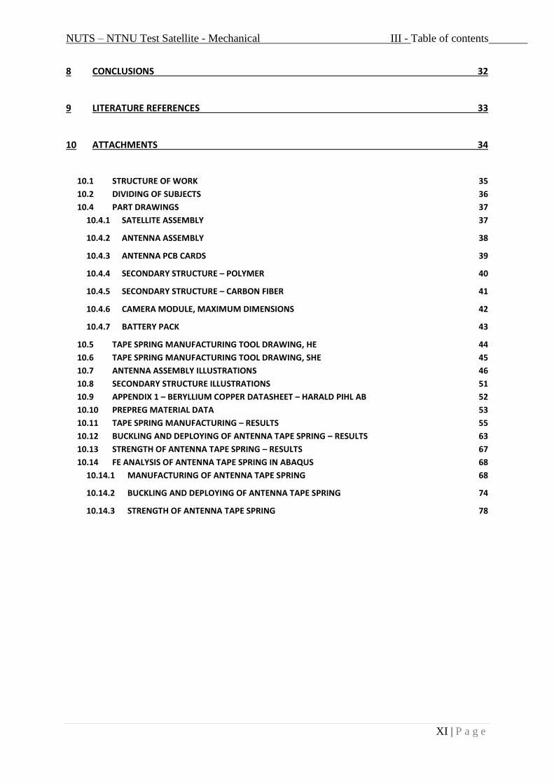
8 CONCLUSIONS 32
9 LITERATURE REFERENCES 33
10 ATTACHMENTS 34
10.1 STRUCTURE OF WORK 35
10.2 DIVIDING OF SUBJECTS 36
10.4 PART DRAWINGS 37
10.4.1 SATELLITE ASSEMBLY 37
10.4.2 ANTENNA ASSEMBLY 38
10.4.3 ANTENNA PCB CARDS 39
10.4.4 SECONDARY STRUCTURE – POLYMER 40
10.4.5 SECONDARY STRUCTURE – CARBON FIBER 41
10.4.6 CAMERA MODULE, MAXIMUM DIMENSIONS 42
10.4.7 BATTERY PACK 43
10.5 TAPE SPRING MANUFACTURING TOOL DRAWING, HE 44
10.6 TAPE SPRING MANUFACTURING TOOL DRAWING, SHE 45
10.7 ANTENNA ASSEMBLY ILLUSTRATIONS 46
10.8 SECONDARY STRUCTURE ILLUSTRATIONS 51
10.9 APPENDIX 1 – BERYLLIUM COPPER DATASHEET – HARALD PIHL AB 52
10.10 PREPREG MATERIAL DATA 53
10.11 TAPE SPRING MANUFACTURING – RESULTS 55
10.12 BUCKLING AND DEPLOYING OF ANTENNA TAPE SPRING – RESULTS 63
10.13 STRENGTH OF ANTENNA TAPE SPRING – RESULTS 67
10.14 FE ANALYSIS OF ANTENNA TAPE SPRING IN ABAQUS 68
10.14.1 MANUFACTURING OF ANTENNA TAPE SPRING 68
10.14.2 BUCKLING AND DEPLOYING OF ANTENNA TAPE SPRING 74
10.14.3 STRENGTH OF ANTENNA TAPE SPRING 78

NUTS – NTNU Test Satellite - Mechanical IV - Diagram list
XII | P a g e
IV. DIAGRAM LIST
FIGURE 1 - SECONDARY STRUCTURE ............................................................................................. 5
FIGURE 2 - SECONDARY STRUCTURE – MILLED GROOVE ................................................................ 6
FIGURE 3 - SECONDARY STRUCTURE - SLOTS ................................................................................. 6
FIGURE 4 – BATTERY PACK WITH SCREWS ..................................................................................... 6
FIGURE 5 - INSERTS ....................................................................................................................... 7
FIGURE 6 - ANTENNA ASSEMBLY ................................................................................................... 8
FIGURE 7 - TAPE SPRING FOLDING PIECES...................................................................................... 8
FIGURE 8 - ANTENNA ASSEMBLY EXPLODED VIEW ......................................................................... 9
FIGURE 9 – TAPE SPRING TOOL ................................................................................................... 10
FIGURE 10 - TAPE SPRING TOOLS MOUNTED TOGETHER .............................................................. 11
FIGURE 11 - TAPE SPRING MODEL ............................................................................................... 11
FIGURE 12 – MANUFACTURE, INITIAL STEP .................................................................................. 12
FIGURE 13 - MANUFACTURE, STEP 1, VON MISES ........................................................................ 12
FIGURE 14 - MANUFACTURE, STEP 2, VON MISES ........................................................................ 12
FIGURE 15 - TAPE SPRING ROLLING STRESSES .............................................................................. 13
FIGURE 16 - TAPE SPRING MANUFACTURE, VON MISES CROSS SECTION ...................................... 13
FIGURE 17 - TAPE SPRING MANUFACTURE, PEEQ CROSS SECTION ................................................ 14
FIGURE 18 – MANUFACTURED TAPE SPRING AFTER SPRING BACK................................................ 14
FIGURE 19 - TAPE SPRING BUCKLING ANALYSIS ASSEMBLY .......................................................... 14
FIGURE 20 - TAPE SPRING BUCKLING, VON MISES ........................................................................ 15
FIGURE 21 - TAPE SPRING BUCKLING, PEEQ ................................................................................. 16
FIGURE 22 - TAPE SPRING STIFFNESS ON EARTH .......................................................................... 16
FIGURE 23 - PREPREG PRODUCTION PROCESS - OWN DRAWN MODEL ......................................... 20
FIGURE 24 - PREPREG LAYUP - [90; +45; 0; 0; -45; 90] - OWN DRAWN MODEL .............................. 21
FIGURE 25 - ELECTROLYTIC PLATING - OWN DRAWN MODEL ....................................................... 23
FIGURE 26 - HTTP://WWW.SPACE.T.U-
TOKYO.AC.JP/CUBESAT/MISSION/DEV/STR/IMG/VIBRATION-S.JPG ............................................ 25
FIGURE 27 – PHASE DIAGRAM FOR BERYLLIUM COPPER, REF; [7] ................................................. 29
FIGURE 28 – ALLOY “25 1/2H” - YIELD STRENGTH/TIME/TEMPERATURE FOR AGE HARDENING, REF;
[7] .............................................................................................................................................. 30

NUTS – NTNU Test Satellite - Mechanical 1 - Introduction
1 | P a g e
1 Introduction
NUTS, NTNU Test Satellite, is a project at NTNU to develop and launch a double CubeSat.
The project is managed by Roger Birkland, who wrote a concept study of developing a
CubeSat at NTNU as his master thesis in 2007. The project participants has since then been
final year students writing both for their pre-project and their master degrees. In the later
years the project has also gained a larger group of voluntary workers. The workforce is a mix
of dedicated people from departments all over NTNU. There are students from electronics,
communications, space technology, physics, cybernetics, computer science and mechanics.
Reference [1].
The main goal is to launch a complete double CubeSat by 2014. At this time the main payload
(load of value) for the satellite is an infrared camera. It is supposed to take pictures of gravity
waves in the upper atmosphere. Gravity waves are waves driving the large scale flows in the
middle atmosphere. They are created by the varying terrain of the earth and the effect of
weather phenomena. The waves are not yet greatly understood. It is possible to observe the
waves from the earth using a telescope. The problem is that there are many atmospheric air
layers between the observatory on earth and gravity waves. In this context they will act as a
filter, and much of the information is lost. It is therefore preferred to obtain the information
with reference above the gravity waves. At this point none of the CubeSat that are sent into
orbit has had an IR-camera as payload. Reference: [1] /payload.
The Department of Engineering Design and Material has the primary responsibility for the
structural part of satellite. In 2011/2012 Kai Inge Rokstad completed his master degree
project for NUTS. His work mainly consisted of developing a concept of using carbon
composite as structural material for the satellite. In cooperation with student Christian
Nomme the project this semester has been to develop and determine a final concept to be
used.
The structure of work is divided using a task tree, se appendix 10.1. It is divided into the main
topics that are conceptualization, analysis, experimental, and production. Different tasks for
primary-, secondary-, tertiary- structure and prototyping has been divided between each other
of us. Christian has had a strong presence on the structural analysis, while I have worked
more with the aspect of material choice and behavior, see appendix10.2.
During this study I have examined different materials for the frame and the secondary
structure. Furthermore I have worked with the concept of the secondary structure and the two
satellite antennas. At last different coating possibilities for the structure is identified.

NUTS – NTNU Test Satellite - Mechanical 2 - Background information
2 | P a g e
2 Background information
2.1 Part description
Following there is a short list that describes the most important parts of the satellite that is
referred to during the report. Reference [1]
2.1.1 Double cube
The satellite is a double CubeSat. Each module is 100x100x113,5 mm. Totally the satellite is
100x100x227 mm (w/l/h).
2.1.2 P-POD
The satellite is hitchhiking with a cargo rocket containing multiple satellites. On the cargo
rocket a P-POD is mounted. Each P-POD contains totally three CubeSats. In other words, it
could contain 3x1 cubes, 1x3 cube, or 1x2 cube + 1x1 cube.
Mainly the P-POD is a rectangular box where the satellite is resting on sliding rails at the P-
POD’s four sides. On the bottom there is a launch spring, and at the top there is a lid that is
opened when the satellites is to be launched into the satellite path.
2.1.3 IR-Camera for scientific payload
The main payload at this point is the IR-camera. The camera is supposed to observe gravity
waves in the upper atmosphere. Until now there are no CubeSats made to observe these
waves. It is possible to observe the waves from the earth, but the air layers in the atmosphere
work as a filter and will degrade the information.
2.1.4 ADCS System
The ADCS, Attitude Determination and Control System, is the system determining the
position of the satellite and will position the desired orientation relatively to the earth.
To determine the orientation of the satellite there is used sun sensors. These sensors will
determine the orientation according to the sun. As long the as the position of the satellite is
known, the orientation relatively to the earth may be calculated.
The attitude control consists of coils of wire at three of the satellite sides. When the coils are
activated with power the magnetic field of the coil will interact with the magnetic field of the
earth. Then you will be able to control the orientation at the xyz-axes.
2.1.5 EPS -Power supply
The EPS consists of the solar cells, power management system, and the batteries.
There are five solar cells modules on the satellite. One consists of two cells, while four
modules consist of four cells each. Totally the satellite is equipped with 18 cells.

NUTS – NTNU Test Satellite - Mechanical 2 - Background information
3 | P a g e
The batteries are the power bank in the system, and will be consumed when the satellite is in
the shade side of the earth, or if the satellite needs excessive power consumption.
The power management system connects the solar cells and the batteries to the electrical
system, and will control the charge cycles.
2.1.6 Battery pack
The satellite is equipped with two battery packs with four batteries each.
2.1.7 Backplane
All the electrical cards in the satellite are connected to the backplane through slots. The
backplane is like the motherboard in an ordinary computer, and is linking the cards together.
Basically it is the communication path in the satellite.
2.1.8 Frame
The frame is the structure in the satellite that is designed to provide the desired stiffness of the
construction. All loads the satellite is exposed to, both external and internal, is addressed the
frame.
It is also the part that is designed to fit the P-POD, where the frame rails are going to slide
along the P-POD rails.
2.1.9 Secondary structure
The secondary structure is the part connecting the internal parts (tertiary structure) with the
frame. It will be exposed to some loads, but should not need to provide excessive stiffness to
the structure.
The secondary structure is in direct contact with the frame, antennas, backplane, PCB cards,
battery pack, camera, and ADCS.
2.1.10 Antennas
The satellite is equipped with two transceivers with separate antennas. One transceiver has an
antenna at 145MHz, and the other has a 437MHz antenna. Together the pair of transceivers
and antennas is connected to the Modem/Microcontroller and constitutes the communication
system.
2.1.11 Transceivers
Two transceivers processes and receives signals from the antennas.

NUTS – NTNU Test Satellite - Mechanical 3 - Method
4 | P a g e
3 Method
3.1 Process of working
The NUTS project is a long running project including people with different background
during a short time interval. This means that the project method changes continuously with
new people. A good solution at one stage of the project can be poor in a later stage with
completely different personnel.
Since we are in an early stage of the project I have tried to build the report flexible. Instead of
present one correct solution, I have presented several different possibilities. All have some
positive aspects and some downsides. The different options are listed with the assumptions for
the suggestion. They also have an introduction to the process, or way of thinking, to ensure
that the reader should be able to make their own judgment on the basis of the report. The
report should be able to be used actively by the new assessments later in the project without
too much background information and research.
During the development of the project we have been addressed to several of concepts directly
or indirectly related to our tasks. They are highly important to understand the contexts in the
big picture. Much of this is well presented by the report of Christian Nomme. Due to limited
space in this report, I choose to restrict reproduction and instead refer to his report for further
details.
NUTS – NTNU Test Satellite - Mechanical 4 - Secondary structure
5 | P a g e
4 Secondary structure
4.1 Description
The secondary structure is the part connecting the internal parts (tertiary structure) with the
frame. It is in direct contact with the frame, antennas, backplane, PCB cards, battery pack,
camera, and ADCS.
4.2 Demands
- Light
- Even mass distribution
- Easy assembly
- Transfer loads evenly to the frame
- Two possibilities
o The frame provides the satellite stiffness
o The secondary structure provide the axial stiffness, and the frame the
diagonally stiffness
- Must assemble the:
o Release springs and switch
o Backplane and modules
o Camera
o Battery pack
o Stiffeners
o ADCS
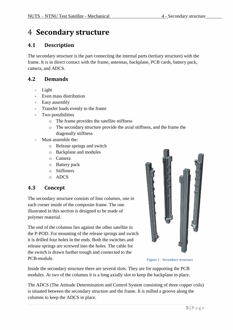
4.3 Concept
The secondary structure consists of four columns, one in
each corner inside of the composite frame. The one
illustrated in this section is designed to be made of
polymer material.
The end of the columns lies against the other satellite in
the P-POD. For mounting of the release springs and switch
it is drilled four holes in the ends. Both the switches and
release springs are screwed into the holes. The cable for
the switch is drawn further trough and connected to the
PCB-module.
Inside the secondary structure there are several slots. They are for supporting the PCB
modules. At two of the columns it is a long axially slot to keep the backplane in place.
The ADCS (The Attitude Determination and Control System consisting of three copper coils)
is situated between the secondary structure and the frame. It is milled a groove along the
columns to keep the ADCS in place.
Figure 1 - Secondary structure

NUTS – NTNU Test Satellite - Mechanical 4 - Secondary structure
6 | P a g e
The photovoltaic system, antenna, stiffener and the ADCS for the top of the satellite is bolted
together as a sandwich. The complete module is then bolted to the satellite. This is done
through eight ears on the stiffener. The ears are squeezed between the secondary structure and
the frame with eight screws, the same screws mounting the top and the bottom of the
photovoltaic system at the sides of the satellite.
4.4 Montage of camera/battery-pack
There are mainly two concepts for mounting of the camera and the battery pack. Which one to
choose is dependent on the final weight of the modules. The weight is not yet known, so it
would be wise to not select one of the concepts at present time.
If the modules are lightweight they may be mounted with the
same concept as the PCB-modules. The camera will have two
slots, one at the top and one at the bottom. The battery pack
could have one in the middle, or one at the top and one at the
bottom. The montage of the satellite will with this concept be
easy.
If the modules are heavyweight they should be screwed in
place directly to the frame. This is done with the same screws
mounting the satellite together. The only difference is that the
nut is mounted on the battery pack and the camera module
instead of the secondary structure. To make the mounting of
the satellite easy the secondary structure is equipped with
supporting structure for the modules.
Figure 3 - Secondary structure - slots
Module
Slots
Backplane
Slots
Figure 2 - Secondary structure – milled groove
Groove for ADCS
Groove for Stiffener
Switch/release spring
Figure 4 – Battery pack with screws

NUTS – NTNU Test Satellite - Mechanical 4 - Secondary structure
7 | P a g e
4.5 Fastenings/screws
4.5.1 Screws
The satellite is mounted together with 40 pcs screws going through the composite frame into
the secondary structure. In addition to this there are 2x8 pcs for the assembly of the antennas,
and 2x8 pcs for assembly of the photovoltaic system, antenna, stiffener and the ADCS
sandwich.
Different screws materials are described in the report by Christian Nomme.
4.5.2 Spacers
To make sure the composite material of the frame is not squeezed there are added spacers in
the frame holes before placing the photovoltaic modules.
4.5.3 Inserts
In the secondary structure there are mounted inserts to
make sure the screws will have properly fixing. In this
way ordinary machine screws can be used. This will
result in good accuracy during montage.
4.5.4 Locktite
If the threads of the screws and/or the inserts/nuts are clean it is a risk that the screws will be
shaken loose because of the vibration during launch. To lock and secure the screws Locktite
could be used. It is a liquid compound to apply the threads that will solidify after montage. It
has many different products. For example has one the possibility for disassembly and another
is permanent and cannot be loosened.
4.5.5 Glue
Glue is another possibility instead of Locktite. This will be permanent, and could only be
applied on the final satellite before launch. The advantage of using glue is it will remove any
slack that may occur in the satellite.
Figure 5 - Inserts

NUTS – NTNU Test Satellite - Mechanical 5 - Antenna system
8 | P a g e
5 Antenna system
5.1 Description
The satellite is equipped with two antennas. The antenna situated at the top of the satellite is a
VHF antenna, and the one at the bottom is a UHF antenna.
Both concepts are flat turnstile antennas (cross dipoles). It consists of four tape springs, each
laid in different direction in the plane.
The antenna is designed according to electrical requirements submitted by Jens Abraham.
5.2 Demands
- Below 3 mm thick tape springs
- Hole for camera lens at 35 mm
- 3 mm free space between PCB cards
- Holes for mounting screws lined up with the stiffener, ADCS and the solar module.
- Proper space for electrical components
- Material of tape springs: Beryllium Copper
5.3 Concept
5.3.1 Design
The antenna is designed as a sandwich structure of
PCB-cards. For detailed view, see appendix 10.7.
In the center of the antenna sandwich there is a
camera lens hole at 35 mm that limits the space
for the electrical components.
The tape spring folding pieces has multiple tasks. When the tape
springs exit the antenna module it has to be curved to preserve its
stiffness. For that reason the curvature of the piece at the exit end
has the ordinary curvature of the antenna tape springs.
The end of the tape spring antennas has to have proper electrical
contact to the PCB card at the montage end of the antenna. The
top folding piece is therefore phased out at the same time as the
curvature is straightened out. To compensate the bottom folding
piece curvature is also straightened and the thickness is increased.
When the antennas are folded around the satellite a kink will cause a radius for the tape
spring. It is important that there will not be any mechanical damage to the tape spring that
prevents the deployment to work properly. At that reason the bottom tape spring folding piece
Figure 7 - Tape spring folding pieces
Figure 6 - Antenna assembly

NUTS – NTNU Test Satellite - Mechanical 5 - Antenna system
9 | P a g e
has a radius at the edge. This will assist in keeping the buckling radius of the tape spring
properly during montage and launch.
The screw holes for the tape springs are situated near the center of the antenna module to get
clear from the stiffener plate and the ADCS. To make sure to keep proper tension the
curvature of the folding pieces is changed first below the first mounting screw.
There are spacers between the PCB cards for the mounting holes for the assembly to keep the
distance constant and the structure under tension.
There are four antenna contacts each placed in each corner of the bottom PCB card. It is
possible, and would have been preferred, to have one contact and lead a copper path to each
of the tape spring antennas. The reason it is split into four is the risk of magnetic field
interference between the copper path on the PCB and the different tape spring antennas. This
could make the antennas inoperable.
5.3.2 Montage
The antenna is assembled in the following order:
1) The screws for the tape springs are fitted in
the tapered holes of the top PCB plate
2) The top PCB plate is placed upside down at
the table. The four tape spring top folding
pieces are mounted
3) The four tape spring antennas are mounted
4) The four tape spring bottom folding pieces are mounted
5) The spacers for the mounting holes at the bottom PCB plate is ether soldered or glued
to the plate.
6) The bottom PCB plate is threaded on the antenna screws, and the nuts are tightened.
The top assembly consists of the solar cell modules, the antenna, the stiffener, and the ADCS.
There are eight montage screws that hold these parts together. The module is then montaged
at the top of the secondary structure with eight screws holding the frame stiffener.
5.3.3 Deployment
The tape spring antennas are wrapped around the satellite in the following order:
1) Each of the bottom antenna springs are folded along the length and the width of the
satellite.
2) The first of the top antenna spring are folded around four corners of the satellite
3) Repeat 2) sequentially with the tree other top tape springs.
The deployment of the tape springs is executed automatically after the launch of the satellite.
The tape springs are held around the satellite with thin nylon thread. When the satellite is in
orbit, the satellite will apply current to a NiCr wire that will burn over the nylon tread. The
nylon thread loses its tension, and the antennas will deploy.
Figure 8 - Antenna assembly exploded view
NUTS – NTNU Test Satellite - Mechanical 5 - Antenna system
10 | P a g e
5.4 FEM-Analysis
The tape springs are made of Beryllium Copper. The tape springs cannot be purchased
finished, so they have to be produced at the NTNU.
There are three aspects to evaluate at this stage of designing the tape springs. It has to be
possible to form the curvature of the tape springs plastically. Secondly it has to be able to
recover its original shape when deployed. At last it should have the required stiffness for the
application.
Abaqus CAE is used for the FEM-Analyses. I have never used, nor had any experience with
Abaqus in advance. At that reason I will concentrate on developing the method for the
analyses. The methods are carefully described step by step in the appendix 10.14 (10.14.1,
10.14.2, and 10.14.3). The idea is that if parameters like length, geometry or material of the
antenna is changed, new analyses should be made based on the manual from the appendix.
5.4.1 Tape spring forming analysis -Manufacturing
To form the tape spring curvature the material has to be formed plastically. The best way to
get the best stress distribution for the tape spring will be pressing the metal plate in a form
made for the whole length of the antenna. Since this will be a small scale production this will
probably be uneconomical. This analysis will therefore be based on that the metal plate is fed
between two roller wheels that form the curvature. To make the analysis as realistic as
possible, it was desirable to model the exact manufacturing process with these tools.
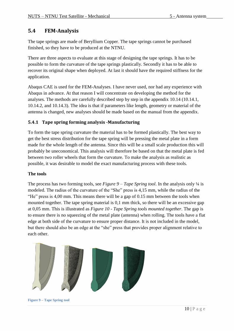
The tools
The process has two forming tools, see Figure 9 – Tape Spring tool. In the analysis only ¼ is
modeled. The radius of the curvature of the “She” press is 4,15 mm, while the radius of the
“He” press is 4,00 mm. This means there will be a gap of 0.15 mm between the tools when
mounted together. The tape spring material is 0,1 mm thick, so there will be an excessive gap
at 0,05 mm. This is illustrated as Figure 10 - Tape Spring tools mounted together. The gap is
to ensure there is no squeezing of the metal plate (antenna) when rolling. The tools have a flat
edge at both side of the curvature to ensure proper distance. It is not included in the model,
but there should also be an edge at the “she” press that provides proper alignment relative to
each other.
Figure 9 – Tape Spring tool

NUTS – NTNU Test Satellite - Mechanical 5 - Antenna system
11 | P a g e
Figure 10 - Tape Spring tools mounted together
It is assumed that the tool material is much stiffer than the antenna material. At that reason the
tools is modelled as solid 3D discreate rigid. They have to be meshed, but Abaqus wont
calculate the stresses in the parts, since they are not important in this context. Before meshing
they have to be converted to a shell element. This has to be done because Abaqus don’t
support 3D discreate rigid elements yet. As a ruule of thoumb, the mesh should be smaller
than the material formed.
Tape Spring
The tape spring material is modeled as solid 3D deformable. It is in this analysis 100x8x0,1
mm (length/width/thickness). It is meshed as C3D8R, an 8-node element. The tape spring has
16 element along the width, and 4 along the thickness, see Figure 11 - Tape spring model.
Figure 11 - Tape spring model
The analysis method
The analysis is performed in explicit mode. It has been many attempts in standard, but there
are many challenges to overcome to succeed. One of them is micro slip, where the friction
between the plate and the tool will alternately slip during step 1. Another is that there are
many points of contact during the analysis. During the press stage 1 the tape spring will be in
contact with the tools in tree points. When using explicit you can define all the surfaces in the
model as contact surfaces. At that way every surface will seek contact without any issues.

NUTS – NTNU Test Satellite - Mechanical 5 - Antenna system
12 | P a g e
Step1
The first step could be a simplification of the manufacturing. If possible it would in reality be
preferred to feed the tape spring plate into the rolling tools. In the analysis the tape spring
plate is laid into the grove of the “She” tool. Step 1 is the step where the two tool pieces is
brought together enclosing the spring plate.
Figure 12 – Manufacture, Initial step
Figure 13 - Manufacture, Step 1, Von Mises
Step2
Step 2 is the step where the tape spring is rolled. The tools are both rotated 90 degrees (Pi/2
rad). The friction applied between the tools and the metal plate pulls the plate through.
Figure 14 - Manufacture, Step 2, Von Mises

NUTS – NTNU Test Satellite - Mechanical 5 - Antenna system
13 | P a g e
Results
The analysis only analyzes a part of the manufacture process of the tape spring. The Figure 15
- Tape spring rolling stresses illustrates the stresses developing in the tape spring during the
plastically deformations. To check the real cross section of importance there is taken out a
section of the plate in the evenly balanced area.
Figure 15 - Tape spring rolling stresses
As illustrated in Figure 16 - Tape spring manufacture, Von Mises cross section the residual
stresses in the cross section is not above 250 MPa. More important the stresses at the edge is
only 6,3 – 20 MPa. The edge is the most vulnerable area during the buckling test, and should
be as low as possible. There are low stresses at the edge because of the excessive gap between
the tape spring and the tool, and then off course because there is no material left to pull the
edge.
Figure 16 - Tape spring manufacture, Von Mises cross section
To check the plastic deformation an PEEQ plot (Plastic Elongation EQuivalent) is illustrated
in Figure 17 - Tape spring manufacture, PEEQ cross section. In the midle there is no plastic
elongation, where the gradient increases towards the edge. This means that the plate is
subjected to bending moment. This is a good verification of the manufacture prosess, where
we only want to bend it and not expose the plate to unnecessary forces or stresses.
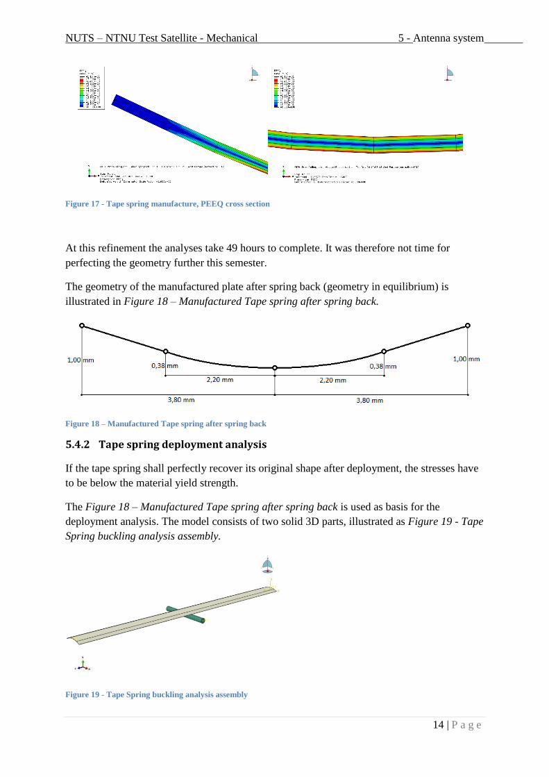
NUTS – NTNU Test Satellite - Mechanical 5 - Antenna system
14 | P a g e
Figure 17 - Tape spring manufacture, PEEQ cross section
At this refinement the analyses take 49 hours to complete. It was therefore not time for
perfecting the geometry further this semester.
The geometry of the manufactured plate after spring back (geometry in equilibrium) is
illustrated in Figure 18 – Manufactured Tape spring after spring back.
Figure 18 – Manufactured Tape spring after spring back
5.4.2 Tape spring deployment analysis
If the tape spring shall perfectly recover its original shape after deployment, the stresses have
to be below the material yield strength.
The Figure 18 – Manufactured Tape spring after spring back is used as basis for the
deployment analysis. The model consists of two solid 3D parts, illustrated as Figure 19 - Tape
Spring buckling analysis assembly.
Figure 19 - Tape Spring buckling analysis assembly
NUTS – NTNU Test Satellite - Mechanical 5 - Antenna system
15 | P a g e
The tape spring is meshed as a C3D8R, 8-node element. It has 15 elements along the
curvature, and 4 elements along the thickness. The tape spring is 100 mm long with the
geometry cross section as manufactured in Chapter 5.4.1, Tape spring forming analysis -
Manufacturing.
The second part, the corner at the satellite, is modeled as discrete rigid. It has a radius at 2 mm
and is 20 mm long.
The analysis is divided into 4 bending steps, and 4 unloading steps. The corner is moved from
its initial position with a radius of 50 mm around the origin to a degree of 45, and back again.
The end of the corner located in origin is fixed against movement in x, y, and z direction, and
rotation around y and z axis. The opposite end is fixed for rotation around y and z axis.
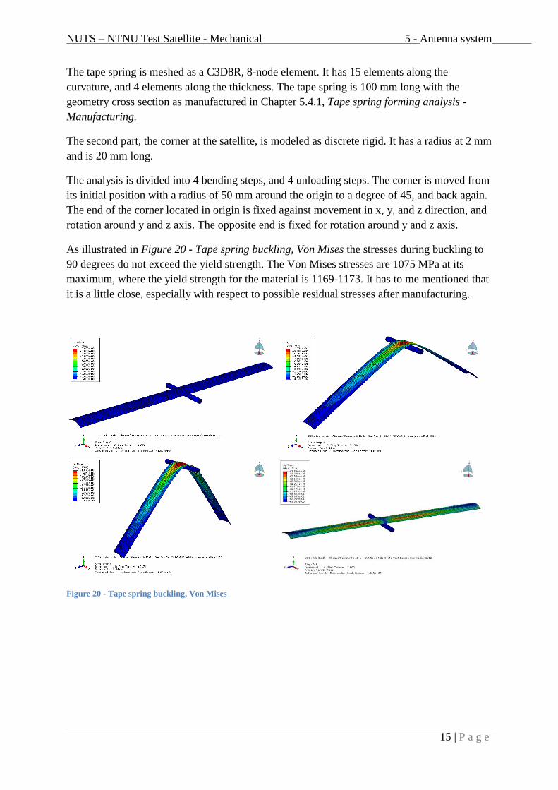
As illustrated in Figure 20 - Tape spring buckling, Von Mises the stresses during buckling to
90 degrees do not exceed the yield strength. The Von Mises stresses are 1075 MPa at its
maximum, where the yield strength for the material is 1169-1173. It has to me mentioned that
it is a little close, especially with respect to possible residual stresses after manufacturing.
Figure 20 - Tape spring buckling, Von Mises

NUTS – NTNU Test Satellite - Mechanical 5 - Antenna system
16 | P a g e
When looking at Figure 21 - Tape spring buckling, PEEQ it is no plastic elongation at all
during buckling. That indicates the tape spring will resume its shape after it is wrapped
around the satellite.
Figure 21 - Tape spring buckling, PEEQ
5.4.3 Tape spring stiffness
The reason for making a curvature for the antenna is to straighten it out after launch. Its
ability to deploy will depend on its geometrical stiffness.
Initially the gravity is almost the same at the earth as the orbit. The difference is that there are
noting that stops the satellite for falling, it is only “missing” the earth. Practically, this means
that there are no gravity forces acting on the tape spring antennas that can make it buckle.
To check its stiffness the gravity effect at earth is
checked anyway. It could also be an easy way to check
the validity of the analyses in a physical test. The antenna
is modeled exactly as the Buckling and deploying of
Antenna Tape Spring analysis, only in full length. The
longest antenna is used as a basis, and it is 700 mm long.
The tape spring is only fixed in the end situated in origin.
The only force introduced in the analysis is the gravity in
–y direction. As illustrated in Figure 22 - Tape Spring
stiffness on earth the displacement in the free end is 174
mm in –y direction. It is a relative high displacement (25% of its length), but the analysis also
imply that it actually will hold without buckling when interacting with the gravity at earth.
The engineering evaluation involves how stiff the antenna actually has to be to function
properly.
What remains to be analyzed is how the antenna responds after deployment. It is important to
know that when deployed it will get an oscillation frequency. How this frequency is damped
after deployment has to be verified to ensure that the antenna reaches equilibrium without
break.
Figure 22 - Tape Spring stiffness on earth

NUTS – NTNU Test Satellite - Mechanical 5 - Antenna system
17 | P a g e
5.5 Production of tape spring antenna
The tape spring has to be made at NTNU. The material is shipped as a plate with the
dimensions 211x800x0,1 mm.
The first step is to cut the plate in desired length and width. According to the tape spring
deployment analysis the width has to be 8 mm. The length is respectively 4x700 and 4x300
mm. The plate is cut with a plate scissor.
The second step is to form the plate with the tool designed for this application. The tool
consists of six wheels. The main forming wheels have the curvature found necessary in the
tape spring forming analysis, and the manufacturing drawings are attached as 10.5 and 10.6.
The upper wheel has a positive curvature, while the lower wheel has a negative curvature. The
two wheels in front and behind the main forming wheels is steering wheels. They are mounted
to prevent the tape spring to slide sideways.
To lower the forces acting at the tape spring folding piece the spring forming should stop 10
mm from the edge of the tape spring. In this way the tape spring will lay naturally flat on the
PCB surface after mounting.
The tape springs has to be heat treated after the forming to regain their original properties. For
further description refer to chapter 6.3.
5.6 Physical bending test
The finished tape spring should be tested physically to verify the analyzed parameters. It is
important to control the bending radius to be sure that it is designed correct to the antenna
module concept. Another test is to find the actual stiffness of the tape spring when properly
deployed. Finally it could be useful to check how vulnerable it is against buckling without
permanent (plastically) deformation.

NUTS – NTNU Test Satellite - Mechanical 6 - Material
18 | P a g e
6 Material
6.1 Frame
6.1.1 Demands
There are both structural and environmental properties of importance when selecting a proper
material for the frame. Some are to satisfy the launch party, and some are internal project
properties.
CubeSat design specification, The CubeSat Program, Cal Poly SLO:
- 2.1.7.1 Total Mass Loss (TML) shall be ≤1.0%
- 2.1.7.2 Collected Volatile Condensable Material (CVCM) shall be ≤0.1%
- 2.2.9 The rail shall not have a surface roughness greater than 1.6 µm
- 2.2.19 Aluminum 7075 or 6061 shall be used for both the main CubeSat
structure and the rails. If other materials are used the developer shall
submit a DAR and adhere to the waiver process
- 2.2.20 The CubeSat rails and standoff, which contact the P-POD rails and
adjacent CubeSat standoffs, shall be hard anodized aluminum to prevent
any cold welding within the P-POD
NUTS project specifications of importance:
- Sufficient stiffness
- Wear against P-POD equal or less relative to aluminum against aluminum.
- Impact strength (Play between P-POD and Satellite)
- Avoid potential accumulation induced from electromagnetic radiation
6.1.1.1 Avoid potential accumulation
In orbit the satellite is exposed for electromagnetic radiation. There is a fear the radiation will
induce potential accumulation in electrical components in the satellite. To avoid this challenge
the frame should be electrical conductive. At this point the danger with this problem is not
identified. It could be a problem, or it could be marginal. The maximum resistance in the
frame is therefore sat to 10 ohm for now.
There is a possibility the frame has low enough electrical resistance in itself. If the frame has
too high resistance it could be solved with a metal coating (chapter 6.1.3.2), or an epoxy
coating with metal particles (chapter 6.1.3.1)
6.1.1.2 Wear of rails
To get the satellite approved for launch it must satisfy the specifications of low wear of the
satellite against the P-POD rails. There is different ways to limit the wear. Either the epoxy
coating need sufficient hardness (Chapter 6.1.3.1), it could be used the approved aluminum
coating (Chapter 6.1.3.2), or it could be used a type of solid lubricant (Chapter 6.1.3.3).

NUTS – NTNU Test Satellite - Mechanical 6 - Material
19 | P a g e
6.1.2 Composites
One of the main goals for the frame it low weight. When it’s desirable to combine it with high
stiffness, composites is a natural option.
Composites are a generic term for a group of materials. A composite is a material composed
of two or more materials with different properties. The idea is to produce a material which is
a combination of several properties which are desired in a particular case.
6.1.2.1 Reinforcement and Matrix – Carbon and Epoxy
There are different types of fibers to choose between. There is for example high modulus
carbon, high strength carbon, E-glass, R-glass, aramid, polyethylene etc. For this application
the high modulus carbon fiber reinforcement is chosen. The tensile strength is at the same
region as the other possibilities, but the tensile modulus is almost the double of high strength
carbon. The downside of this fiber is that the cost is almost 4 times higher than any of the
other fibers.
There are mainly three different matrixes to choose between. They are Epoxy, Phenolic, and
Bismaleimide.
Table 1 - Matrices – Hexcel datasheet
Epoxy Phenolic Bismaleimide
Advantages - Excellent
mechanical
performance
- Good environmental
resistance and high
toughness
- Easy processing
- Excellent fire
resistance
- Good temperature
resistance
- Low smoke and
toxic emission
- Rapid cure
- Economic
processing
- Excellent resistance to
high temperatures
- Service temp up to
260 C
- Good mechanical
characteristics
- Good resistance to
chemical agents, fire
and radiation
For this application epoxy will be the best choice for matrix, mainly for its good mechanical
properties. Reference [2].
6.1.2.2 PrePreg
To make the satellite of carbon fiber and epoxy the PrePreg concept is used. PrePreg is a mat
of fiber reinforcement and matrix. It can either be delivered as unidirectional fibers (UD) or
weaved fibers. The PrePreg mat is uncured, and has to be stored cold until it is used.
There are mainly two methods of applying PrePreg on a mold that is appropriate for us. It is
the vacuum bag process, and the autoclave process.
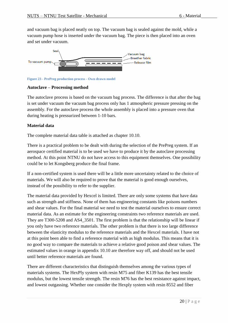
Vacuum bag – Processing method
It is the vacuum bag process we have the ability to use at NTNU. The process is illustrated as
Figure 23 - PrePreg production process - Own drawn model . First the mold is applied
release wax. Then the PrePreg is placed around the mold. Following a release film, breather,
NUTS – NTNU Test Satellite - Mechanical 6 - Material
20 | P a g e
and vacuum bag is placed neatly on top. The vacuum bag is sealed against the mold, while a
vacuum pump hose is inserted under the vacuum bag. The piece is then placed into an oven
and set under vacuum.
Figure 23 - PrePreg production process - Own drawn model
Autoclave – Processing method
The autoclave process is based on the vacuum bag process. The difference is that after the bag
is set under vacuum the vacuum bag process only has 1 atmospheric pressure pressing on the
assembly. For the autoclave process the whole assembly is placed into a pressure oven that
during heating is pressurized between 1-10 bars.
Material data
The complete material data table is attached as chapter 10.10.
There is a practical problem to be dealt with during the selection of the PrePreg system. If an
aerospace certified material is to be used we have to produce it by the autoclave processing
method. At this point NTNU do not have access to this equipment themselves. One possibility
could be to let Kongsberg produce the final frame.
If a non-certified system is used there will be a little more uncertainty related to the choice of
materials. We will also be required to prove that the material is good enough ourselves,
instead of the possibility to refer to the supplier.
The material data provided by Hexcel is limited. There are only some systems that have data
such as strength and stiffness. None of them has engineering constants like poisons numbers
and shear values. For the final material we need to test the material ourselves to ensure correct
material data. As an estimate for the engineering constraints two reference materials are used.
They are T300-5208 and AS4_3501. The first problem is that the relationship will be linear if
you only have two reference materials. The other problem is that there is too large difference
between the elasticity modulus to the reference materials and the Hexcel materials. I have not
at this point been able to find a reference material with as high modulus. This means that it is
no good way to compare the materials to achieve a relative good poison and shear values. The
estimated values in orange in appendix 10.10 are therefore way off, and should not be used
until better reference materials are found.
There are different characteristics that distinguish themselves among the various types of
materials systems. The HexPly system with resin M75 and fiber K139 has the best tensile
modulus, but the lowest tensile strength. The resin M76 has the best resistance against impact,
and lowest outgassing. Whether one consider the Hexply system with resin 8552 and fiber

NUTS – NTNU Test Satellite - Mechanical 6 - Material
21 | P a g e
IM7 you got the best strength. Finally the resin M18 has lowest moisture uptake and achieves
the best surface finish.
6.1.2.3 PrePreg Layup
The layup which may be suitably for the satellite is the following:
[90; +45; 0; 0; -45; 90]
Figure 24 - PrePreg Layup - [90; +45; 0; 0; -45; 90] - Own drawn model
Different load scenarios:
The frame is mostly vulnerable to diagonal displacement. This load case cause bending
moment in the walls. The tension will be at its maximum at the surface. It is therefore most
convenient to have the outer composite layer in the direction of the tensile stresses. As long as
the reference direction is axially relative to the satellite this layer will be 90°. At the opposite
side of the tensile side the composite will be in compression. The strength in compression is
smaller. In this case it is important that the quality is good to prevent buckling and/or
delamination of the layer.
The satellite could also be exposed to torsion. At this reason there are two layers of 45°.
The core layers are at 0°. This is to take care of the axial forces that will occur.
The dilemma with this kind of layup is it is not symmetric, nor balanced. This may give
undesirable effects for e.g. during temperature changes.
6.1.3 Surface treatment
There are two challenges to overcome with a proper surface treatment. The first is wear, the
second is electrical conductivity.
6.1.3.1 Epoxy coating
A possibility is an electrically conductive epoxy coating. There is different epoxy on the
market that has achieved good conductivity by blending in silver particles.
An aspect to investigate before choosing such a solution is the wear rate of the optional
coating. Since silver in practice is a solid lubricant it may be positive gain by using a silver

NUTS – NTNU Test Satellite - Mechanical 6 - Material
22 | P a g e
epoxy as a top coat sliding against the P-POD rail. At the same time the particles may
increase the softness of the coating, and thereby be more vulnerable against two and three
body wear.
6.1.3.2 Metal coating
A metal coating could handle both wear and have high electrical conductivity. If for example
a hard anodized aluminum coating is used, we will get within the CubeSat design
specification, The CubeSat Program, Cal Poly SLO. There are different ways to coat the
satellite, all with advantages and drawbacks.
Since the satellite is non-metallic, I want to point out two methods of metal coating. The first
is plating on non-conducting materials, and the second is thermal sprayed coatings.
Plating on non-conducting materials
Plating is originally only possible on conductive metals. Due to this non-conductive materials
will need preprocessing to get conductive before the plating process is done. To do this an
electroless process is used to apply a conductive metallic layer of nickel or copper. The same
process is used when the PCB (Printed Circuit Board) is plated with for example chrome.
There are some steps involved before the plating is done:
1) The surface has to be chemical etched to produce pores in the material for the metal to
be anchored. This could be Sulphuric acid/chrome acid mixture.
2) The surface is then activated by colloidial palladium.
3) The palladium needs to be activated. A chemical treatment leaves the palladium atoms
in the pores in the material.
4) The three first steps prepare the surface of the material for metal deposition. In this
step one conduct an autocatalytic (electroless) deposition of nickel or copper. A thin
and continuous metal layer will be deposited in some minutes.
When the surface is prepared the part is ready for the electrolytic plating.

NUTS – NTNU Test Satellite - Mechanical 6 - Material
23 | P a g e
Plating is a process where the part is added a metal coating by electrolysis in a bath.
Figure 25 - Electrolytic plating - Own drawn model
Current is applied the plating metal. The plating metal is going through an anodic reaction
where metal dissolves as metal ions in the electrolyte (corrosion process). The metal ions are
then deposited on the part through a cathodic process.
Before the plating is done there are some procedures to be followed:
1) The part has to be thoroughly cleaned to remove contaminations.
2) The surface oxide film has to be removed by electrolytic cleaning in H2SO4 bath.
3) Washing to remove detergents.
There are multiple different metals that can be plated. In this case it would be practical to
plate aluminum since it is already verified by the launch team.
Anodizing is a surface treatment that uses an electrochemical process to transform the
aluminum surface. There are especially two properties which we in this case are looking for.
First: The surface gets increased wear resistance. Second: The electrical resistance is
increased. The first is important since the satellite will be exposed to vibrations during launch.
A plated aluminum layer is thin. It has its limit in both wear and possibility for delamination
from the substrate. The last is important to limit the electron transfer between the P-POD and
the satellite. If an electron transfer between the surfaces is allowed, this can lead to cold
welding. This is a phenomenon that can lead to severe damage to the coating, and will
increase the wear rate significantly.
During the electrochemical process aluminum oxide is transformed from aluminum on the
anode: 2Al(s) + 3H2O Al2O3(s) + 3H2(g). The hydrogen gas is formed at the cathode. The
oxide on the surface is formed on the interface between the aluminum and the oxide. This
means that the electrolyte needs to etch on top of the oxide layer to keep the pores open to
keep the resistance sufficiently low. When the thickness increases, and thereby the resistance,
the oxide formation growth gradually decreases. When the etching on the top of the oxide
layer and the formation at the bottom gets equal, the maximum thickness is reached.

NUTS – NTNU Test Satellite - Mechanical 6 - Material
24 | P a g e
The other coating technique is thermal spraying. There are a variety of different methods,
each for their particular applications. In common to them all is that they are a cold spray
technique. That means it’s a kinetic spray process where powder particles are accelerated to
ultra-high velocities by a jet of compressed gas. The velocity varies between 300-1200 m/s. In
this way the particles don’t need too high temperature to get a solid state plastic deformation
on impact with the substrate.
To choose the proper technique it is important to examine what kind of requirements one has
for the coating, what kind of effect it has on the substrate, economic aspect, and the practical
implementation. In this case I wish to keep the temperature of the substrate as low as possible.
Even though thermal spraying is a cold technique the particles will be partially molten, and at
the end increase the temperature of the substrate.
Flame powder spray could be an option. The technique is both cheap and easy to handle. The
particles have low temperature, but also low velocities. The issue with this is that it gives
some porosity and low density with low bond strength. For a better coating quality there are
some models with pressurized inert gas from a remote feeder. In this way higher velocity are
achieved, at the same time as it cools the substrate. The result is a less porous coating.
HVOF (High Velocity Oxy Fuel) is the same type of technique as Flame powder spray, but is
built to achieve an extremely high spray velocity. The coating will get one of the highest
density and strength compared with the other techniques, but the expense and usability will
naturally increase.
As mentioned, the coatings of thermal spray are often associated with porosity. This is
especially critical in situations when combining corrosion, stresses and wear. Since we are not
too concerned of corrosion and stresses, it is more important to look at the combination
between wear and delamination. To improve the bond between the coating and the substrate it
is important to grit blast to proper roughness.
What kind of technique to choose depends on the situation at the time of the decision. At this
point the effect of electromagnetic radiation is unknown. The plating method gives a
smoother and thinner surface coating. The downside is the complexity of the process. It is also
possible to coat it on the inside of the structure. On the other hand, thermal spraying is easier
to only coat selected parts of the satellite. The downside is it’s not that suitable for coating the
inside of the satellite.
For the metal coating chapter I refer to reference [2].
6.1.3.3 Solid lubricant
If the resistance for the carbon fiber frame is low enough it may not be necessary with a
coating except the issue with wear.
As a little unconventional method, I would like to mention solid lubricant as a possibility.
Solid lubricant is a solid material that separate two surfaces and acts like a low friction slip
film. One lubricant that has shown its good properties in vacuum is molybdenum disulfide.

NUTS – NTNU Test Satellite - Mechanical 6 - Material
25 | P a g e
While other lubricants are unstable, and may evaporate in vacuum, molybdenum disulfide
will keep its properties. It has a lamella structure that will slide freely over each other when
exposed to two surfaces sliding. It is the low shear forces that occur between the sulfur
molecules that is providing this process. In this way the wear between the P-POD and satellite
rails may be reduced.
Referring to references: [2], and [3].
6.1.4 Material testing
6.1.4.1 Wear
To get the satellite verified to be launched it has to overcome the wear specifications. The
rails in the P-POD, the launch container, are made of anodized aluminum. To secure metallic
compatibility they have specified that the satellite also should be in aluminum. To ensure no
electron transfer between the contact surfaces that can cause cold welding the rails should also
be hard anodized.
If we change the material for the rails to a non-metallic material we will avoid the challenge
with cold welding. What we have to convince is that the wear and the possibility of
interlocking of the component is at an accepted level.
Full scale wear test
The most accurate test is to test the satellite frame with
the proper weight inserted in an authentic P-POD. The
P-POD will be clamped to a vibration disk on the
vibration testing machine. It will then be tested for a
sinus vibration that emulates the actual launch.
With such a test one can obtain proper data for wear
along the rails, but more important, the edges. There is,
and should be, a little clearance between the satellite and
the P-POD. In that way the satellite will be able to twist.
The end of the rails will get a point load from both the
weight and the kinetic energy of the satellite. If we also
add sliding between the surfaces in contact we will get
significantly higher wear.
NUTS do have a P-POD available that may be used for this test. It is certainly thus possible,
but it depend on if it is adequately enough for the launch team with a more simple test for
wear.
Figure 26 - http://www.space.t.u-
tokyo.ac.jp/cubesat/mission/dev/str/img/vibratio
n-s.jpg
NUTS – NTNU Test Satellite - Mechanical 6 - Material
26 | P a g e
Pin-on-disk wear test
Although the full scale test will give the most authentic results, it may be things like
economy, time consumption, equipment availability and actual needs that are in favor for
more simple wear tests.
One of this wear tests is pin-on-disk. This test consists of the test material exposed to an
aluminum ball that is sliding over the surface. The aluminum ball is mounted to a motorized
arm. During the test the friction between the aluminum ball and test material is logged. After
the test is performed the wear area can be analyzed for wear.
Like every other simplified wear test it is important to know it is not a direct connection
between the test results and the real wear inside the P-POD. It is only to be used as a
comparison between other relevant materials exposed to the same test. It is thus possible to
see if the material is better or worse than the reference material.
In our case it is natural to select the reference material as anodized aluminum. The aim for the
test is then to ether get the same or better wear resistance between the aluminum sphere and
the relevant material than aluminum against aluminum.
6.1.4.2 Spectroscopy
Before launch the satellite has to be tested for outgassing. The satellite is first outgassed in a
vacuum own for a certain time. Afterwards the satellite is tested in a spectroscopy analyzer.
The machine set the satellite under vacuum and heat and analyses the output gases for
different atoms. The main goal for this test is to ensure that there are no unwanted elements
that are released during launch. It is not expected many surprises during this test from the
carbon fiber or the polymer we are going to use, except for the adhesives. It is thus much
more important for the electrical components as they are made of many different types of
exotic elements
6.1.4.3 Electrical resistance
An important aspect is to test the resistance in the satellite frame from end to end. It should
not exceed 10 ohm. This is relevant if the satellite is not coated with a metallic coating.

NUTS – NTNU Test Satellite - Mechanical 6 - Material
27 | P a g e
6.2 Secondary structure
6.2.1 Demands
The secondary structure is not supposed to contribute with additional stiffness, but rather be a
link between all the parts inside and outside the satellite.
CubeSat design specification, The CubeSat Program, Cal Poly SLO:
- 2.1.7.1 Total Mass Loss (TML) shall be ≤1.0%
- 2.1.7.2 Collected Volatile Condensable Material (CVCM) shall be ≤0.1%
NUTS project specifications of importance:
- Sufficient strength to carry…
o …loads from satellites the neighbor satellite inside the P-POD
o …loads from internal components
o …receive and transmit bolt tension
- As low weight as possible
- Should have good damping properties
- Withstand vacuum without excessive deformation
6.2.2 Composite
Originally the satellite stiffness is gained by the frame alone. The secondary structure is a one
single piece in the axial direction, at the same time as it is the piece laying against the next
satellite in the P-POD. This means it is perfect to provide the axial stiffness in the satellite.
If it gets desired to design the satellite with a stiffness contribution from both the frame and
the secondary structure a composite material may be used. The positive aspects with carbon
composite material is a more similar thermal expansion, it has high strength and high
elasticity modulus. The downside is the extra weight it will get.
To take account for the extra strength and stiffness there is designed a lightened version of the
secondary structure. The volume is 72,4 cm3, instead for the original 92.6 cm
3. The drawings
are attached as 10.4.4 and 10.4.5.
6.2.3 Polymer - Solid and foam
The secondary structure is originally meant to only take care of the mounting of the satellite
parts. We can therefore accept a relative low stiffness and strength. An option is to use a
polymer, ether as pure solid or as foam.
A solid polymer material is significantly stronger (~x20) and stiffer than the same material in
foam form. However, if the stiffness and strength is not needed, the foam material will be
around 20 times lighter. Another aspect is that a polymer in solid form is more ductile, while
the foam is more brittle. The vacuum properties are also a more difficult subject when dealing
with foam. One positive aspect with both solid and foam polymer is its ability to damping the

NUTS – NTNU Test Satellite - Mechanical 6 - Material
28 | P a g e
vibration of the components inside the satellite. It will also be significantly more ductile than
composite material, meaning it will address displacement in the satellite without introducing
unnecessary stresses to the inner satellite parts.
6.2.4 Comparison overview between relevant materials
A comparison between the relevant materials for the secondary structure:
Type Material Density
[kg/m2]
Secondary
Structure
Weight
[g]
Strength
[MPa]
E
Module
[MPa]
Max
Temp
[C°]
Outgassing
% TML % CVCM
CF CF-Compound
(PPS-HM)
1800 130,32 200 49000 ~0,15 ~0,01
CF-Compound
(PPA-HM)
1800 130,32 280 41000 ~0,15 ~0,01
Polymer
Polystyrene
(PS)
1050 97,23 46
-60
3000
-3600
240 0,09 0,00
Polyethylene
(HDPE)
940
-965
89,35 20
-32
600
-1400
120
-130
0,58 0,19
Polypropylene
(PP)
902
-907
83,98 25
-30
800
-1300
160
-165
0,37 0,17
Polyether ether
ketone
(PEEK)
1320 122,3 99
-100
3600 343 0,20 0,00
Foam
Polystyrene
28-45 4,16 0,8
Polyethylene 25 2,31 0,3
-1
0,79 0,25
Polypropylene 28
-33
3,06 0,25 -70/
+70
% TML: Total Mass Loss, % CVCM: Collected Volatile Condensable Material.
Material data is obtained from references [4], [5], and [6]
The volume for the secondary structure when using CF is 72,4 cm3, and when using polymer
is 92,6 cm3.
As the table indicates CF-Compound, Polystyrene (PS), or Polyether ether ketone (PEEK) is
the best choice according to low outgassing. If a CF-Compound material should be used the
strength and the stiffness should be taken into account during the structural analysis. They are
both stiff and strong, but have high weight. According to weight the foam material is far
superior. It is important to notice one should get hold on foam material with higher density. It
will then gain more weight, but it will still be highly competitive after 5-10 times the weight
in the table.
Which material to use cannot be decided until the satellite concept is selected.

NUTS – NTNU Test Satellite - Mechanical 6 - Material
29 | P a g e
6.3 Antenna tape spring
The material used for the tape spring is Beryllium Copper. For the datasheet, refer to appendix
10.9.
At arrival the tape spring has following properties:
- EN CW101C R 580
- Alloy 25
- Temper 1/2H
- Yield Strength Rp 0,2 585 N/mm^2
- Thickness t 0,10 +/-0,004 mm
- With w 211 mm
- Length l 800 mm
The ASTM designation is C17200.
The temper 1/2H stands for “Half Hard”. That means the material has been hardened (H) by
cold working. If the material has been heat treated by the standard heat treatment the temper
would be “1/2HT”.
Figure 27 – Phase Diagram for Beryllium Copper, ref; [7]
According to Figure 27 – Phase Diagram for Beryllium Copper, ref;, when heating above
1300 F (704 C°) the beryllium dissolve in the alpha phase. If it is quickly cooled down to
room temperature the beryllium maintains in solid solution. In this way the material gets soft
NUTS – NTNU Test Satellite - Mechanical 6 - Material
30 | P a g e
and ductile. The process is called annealing. Annealing should be done to prepare the material
for age hardening, but may be unnecessary because it’s often a part of the production process
in the manufacture factory.
The gamma phase is below 1100 F (593 C°). Here there is limited solubility of beryllium, and
this characteristic is what causes the hardening. After annealing the material has
supersaturated beryllium solid. When heat treated in this phase the solid cause precipitation,
and the material is hardened.
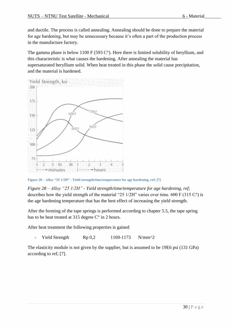
Figure 28 – Alloy “25 1/2H” - Yield strength/time/temperature for age hardening, ref; [7]
Figure 28 – Alloy “25 1/2H” - Yield strength/time/temperature for age hardening, ref;
describes how the yield strength of the material “25 1/2H” varies over time. 600 F (315 C°) is
the age hardening temperature that has the best effect of increasing the yield strength.
After the forming of the tape springs is performed according to chapter 5.5, the tape spring
has to be heat treated at 315 degree C° in 2 hours.
After heat treatment the following properties is gained
- Yield Strength Rp 0,2 1169-1173 N/mm^2
The elasticity module is not given by the supplier, but is assumed to be 19E6 psi (131 GPa)
according to ref; [7].

NUTS – NTNU Test Satellite - Mechanical 7 - Satellite prototype
31 | P a g e
7 Satellite prototype
To make a prototype we had to start with machining a mold of aluminum for the stiffeners:
The original satellite mold from last semester had to be machined because of high surface
roughness and wrong radius at the edges, and a bolt failure:
A jig to press the PrePreg into the corners were constructed:
PrePreg was cut in sections. It was then laid up in the satellite mold and on a glass plate for
coil plates and cellar panels.
The results after curing in own at 175 C for 2 hours:

NUTS – NTNU Test Satellite - Mechanical 8 - Conclusions
32 | P a g e
8 Conclusions
The secondary structure, that assembles all the internal parts of the satellite, is derived as four
columns, one in each corner. Each column is equipped with slots for the PCB modules. To
mount the battery pack and the camera two solutions is derived. The first involves using
regular slots, while the other is to use the main assembly screws. Which to choose depends on
the final weight of the modules. Both for the stiffener and the ADCS system there are milled
grooves to fit the module fastening ears between the frame and the secondary structure.
There are two flat turnstile antennas (cross dipoles) mounted at the satellite. The antenna tape
springs, made of Beryllium Copper, are wrapped around the satellite during launch. When the
satellite is in orbit they are deployed by a NiCr wire that burns over the nylon thread that
keeps the antennas in place.
The tape spring curvature has to be manufactured at NTNU. A FEM-Analysis if the
manufacturing of the tape springs is carried out. After rolling the antennas the curvature will
experience a spring back, i.e. the curvature will flatten. The curvature results are then used as
input for a buckling analysis. When a purely elastic buckling behavior is verified, the
curvature is examined for stiffness.
According to the results the antenna tape springs after manufacturing with tools at 4 mm
radius will both withstand buckling with purely elastic behavior and be stiff enough to deploy.
What should be investigated are the actual loads and fluctuations that will occur for the
antennas in orbit. This will determine if the antenna geometry is good enough or if they
should be modified.
The material for the frame is PrePreg of carbon fiber with epoxy matrix. If an aerospace
material is used the manufacturing has to be carried out of someone who have access to the
autoclave process. If we want to use an ordinary material we have to investigate the behavior
and the approval of the material.
To overcome the challenges with wear and conductivity there are investigated different types
of surface treatment. The best could be an anodized aluminum coating using a non-conducting
plating method or thermal spraying. This method will have high cost, and it must be
considered whether we get approved other options like e.g. epoxy coating.
For the secondary structure the materials CF-Compound, Polystyrene (PS), and Polyether
ether ketone (PEEK) is the best choice according to low outgassing and high strength.
Polystyrene has the lowest weight, but is also the weakest. Before a material is selected it
must be considered whether or not the secondary structure shall be used to relive stiffness of
the satellite frame.
A prototype of the satellite is carried out in PrePreg of carbon fiber. The stiffeners and the
plates for the cellar panels and ADCS system are also made. The next step is to cut out the
windows of the satellite frame and cut out the right shape of the panels.

NUTS – NTNU Test Satellite - Mechanical 9 - Literature references
33 | P a g e
9 Literature references
[1] "NUTS - NTNU Test Satellite, a Norwegian CubeSat Project," [Online]. Available:
http://nuts.cubesat.no/.
[2] Hexcel, "Prepreg Technology," [Online]. Available: www.hexcel.com.
[3] R. Johnsen, O. Ø. Knudsen and N. Espallargas, Lecture notes from TMM4205 Tribology.
[4] "Solid Film Lubricants," [Online]. Available:
http://www.machinerylubrication.com/Read/861/solid-film-lubricants .
[5] "MatBase," [Online]. Available:
http://www.matbase.com/material/polymers/commodity/hdpe/properties .
[6] "Nasa Outgassing Database," [Online]. Available:
http://outgassing.nasa.gov/cgi/uncgi/search/search_ad.sh.
[7] "Lati High Performance CF," [Online]. Available:
http://www.lati.com/en/news/2009/high_modulus_carbon_fibres_in_super-
structural_compounds.html .
[8] B. Wellman, Guide to Beryllium Copper.

NUTS – NTNU Test Satellite - Mechanical 10 - Attachments
34 | P a g e
10 Attachments
10 ATTACHMENTS 34
10.1 STRUCTURE OF WORK 35
10.2 DIVIDING OF SUBJECTS 36
10.4 PART DRAWINGS 37
10.4.1 SATELLITE ASSEMBLY 37
10.4.2 ANTENNA ASSEMBLY 38
10.4.3 ANTENNA PCB CARDS 39
10.4.4 SECONDARY STRUCTURE – POLYMER 40
10.4.5 SECONDARY STRUCTURE – CARBON FIBER 41
10.4.6 CAMERA MODULE, MAXIMUM DIMENSIONS 42
10.4.7 BATTERY PACK 43
10.5 TAPE SPRING MANUFACTURING TOOL DRAWING, HE 44
10.6 TAPE SPRING MANUFACTURING TOOL DRAWING, SHE 45
10.7 ANTENNA ASSEMBLY ILLUSTRATIONS 46
10.8 SECONDARY STRUCTURE ILLUSTRATIONS 51
10.9 APPENDIX 1 – BERYLLIUM COPPER DATASHEET – HARALD PIHL AB 52
10.10 PREPREG MATERIAL DATA 53
10.11 TAPE SPRING MANUFACTURING – RESULTS 55
10.12 BUCKLING AND DEPLOYING OF ANTENNA TAPE SPRING – RESULTS 63
10.13 STRENGTH OF ANTENNA TAPE SPRING – RESULTS 67
10.14 FE ANALYSIS OF ANTENNA TAPE SPRING IN ABAQUS 68
10.14.1 MANUFACTURING OF ANTENNA TAPE SPRING 68
10.14.2 BUCKLING AND DEPLOYING OF ANTENNA TAPE SPRING 74
10.14.3 STRENGTH OF ANTENNA TAPE SPRING 78

NUTS – NTNU Test Satellite - Mechanical 10 - Attachments
35 | P a g e
10.1 Structure of work

NUTS – NTNU Test Satellite - Mechanical 10 - Attachments
36 | P a g e
10.2 Dividing of subjects
Christian Nomme Kim Sandvik
Primary structure Evaluation of concept
CAD of frame
CAD of stiffeners
Basis for analysis
Static frame analysis
Modal frame analysis
Material selection of frame
Coating?
Material orientation of frame
Implementation of material-
properties in analysis.
Material testing
Secondary structure Static analyses of structure Evaluation of concept
CAD of secondary structure
Material selection of secondary
structure
Prototype Main structure
Stiffeners
Auxiliary equipment
Prototype testing
Main structure
Stiffeners
Secondary structure
Prototype testing
Tertiary structure Photovoltaic system concept Antenna system concept

NUTS – NTNU Test Satellite - Mechanical 10 - Attachments
37 | P a g e
10.4 Part drawings
10.4.1 Satellite assembly

NUTS – NTNU Test Satellite - Mechanical 10 - Attachments
38 | P a g e
10.4.2 Antenna assembly

NUTS – NTNU Test Satellite - Mechanical 10 - Attachments
39 | P a g e
10.4.3 Antenna PCB cards
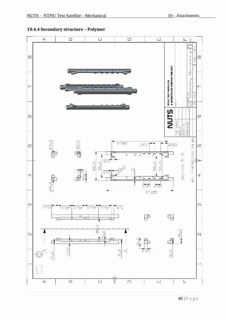
NUTS – NTNU Test Satellite - Mechanical 10 - Attachments
40 | P a g e
10.4.4 Secondary structure – Polymer

NUTS – NTNU Test Satellite - Mechanical 10 - Attachments
41 | P a g e
10.4.5 Secondary structure – Carbon fiber

NUTS – NTNU Test Satellite - Mechanical 10 - Attachments
42 | P a g e
10.4.6 Camera module, maximum dimensions

NUTS – NTNU Test Satellite - Mechanical 10 - Attachments
43 | P a g e
10.4.7 Battery pack
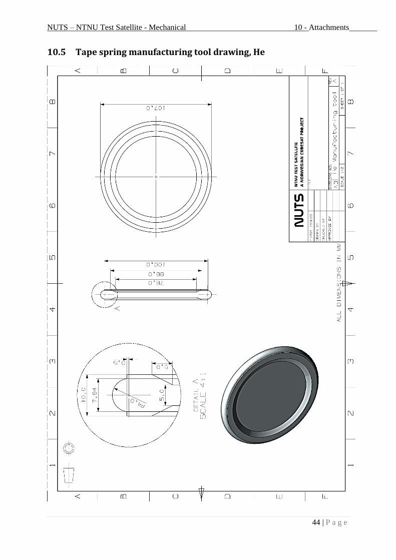
NUTS – NTNU Test Satellite - Mechanical 10 - Attachments
44 | P a g e
10.5 Tape spring manufacturing tool drawing, He

NUTS – NTNU Test Satellite - Mechanical 10 - Attachments
45 | P a g e
10.6 Tape spring manufacturing tool drawing, She

NUTS – NTNU Test Satellite - Mechanical 10 - Attachments
46 | P a g e
10.7 Antenna assembly illustrations
Assembly overview:
Assembly top close-up:
Assembly bottom close-up:

NUTS – NTNU Test Satellite - Mechanical 10 - Attachments
47 | P a g e
Disassembly of top PCB card:
Exploded view 1:

NUTS – NTNU Test Satellite - Mechanical 10 - Attachments
48 | P a g e
Exploded view 2:
Tape spring folding pieces 1:
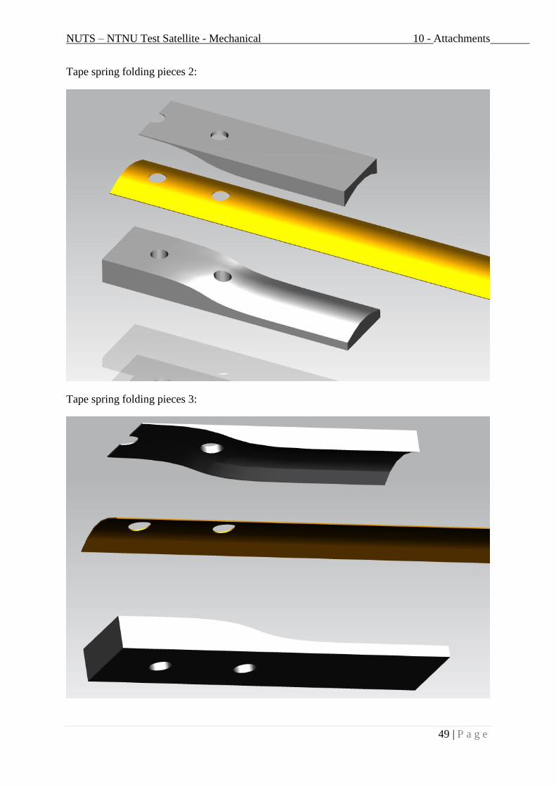
NUTS – NTNU Test Satellite - Mechanical 10 - Attachments
49 | P a g e
Tape spring folding pieces 2:
Tape spring folding pieces 3:

NUTS – NTNU Test Satellite - Mechanical 10 - Attachments
50 | P a g e
Assembly exploded view, 2D:

NUTS – NTNU Test Satellite - Mechanical 10 - Attachments
51 | P a g e
10.8 Secondary structure illustrations
Secondary structure for polymer material:

NUTS – NTNU Test Satellite - Mechanical 10 - Attachments
52 | P a g e
10.9 Appendix 1 – Beryllium Copper datasheet – Harald Pihl AB

NUTS – NTNU Test Satellite - Mechanical 10 - Attachments
53 | P a g e
10.10 PrePreg Material Data
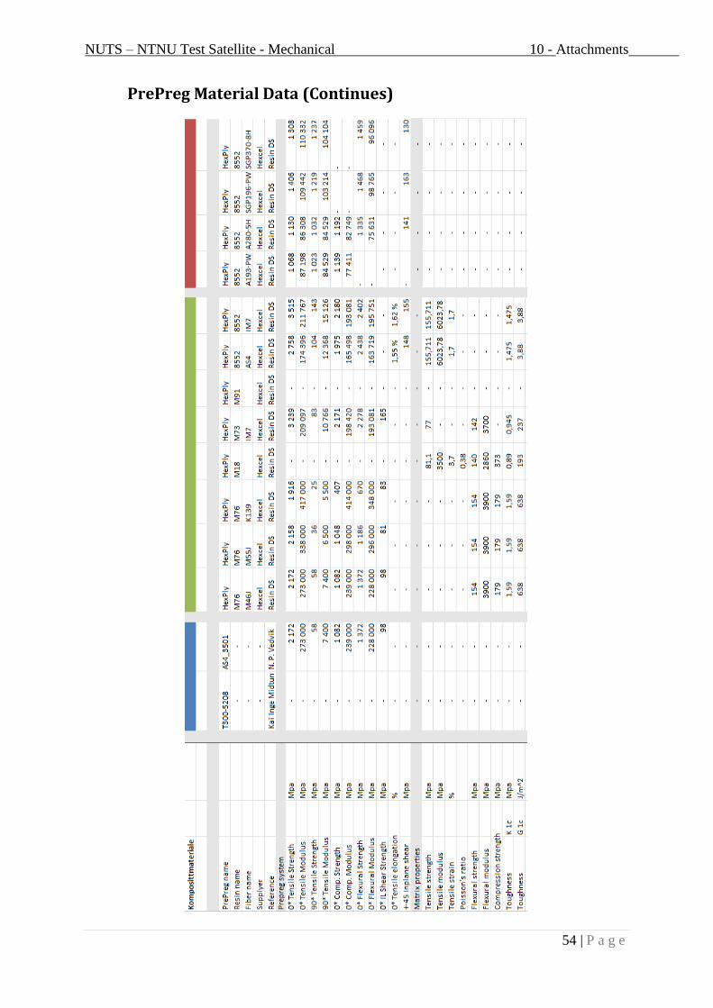
NUTS – NTNU Test Satellite - Mechanical 10 - Attachments
54 | P a g e
PrePreg Material Data (Continues)
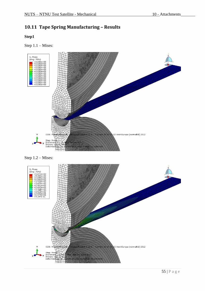
NUTS – NTNU Test Satellite - Mechanical 10 - Attachments
55 | P a g e
10.11 Tape Spring Manufacturing – Results
Step1
Step 1.1 – Mises:
Step 1.2 – Mises:

NUTS – NTNU Test Satellite - Mechanical 10 - Attachments
56 | P a g e
Step 1.3 – Mises:
Step2
Step 2.1 – Mises:

NUTS – NTNU Test Satellite - Mechanical 10 - Attachments
57 | P a g e
Step 2.2 – Mises:
Step 2.3 – Mises:

NUTS – NTNU Test Satellite - Mechanical 10 - Attachments
58 | P a g e
Step 2.4 – Mises:
Step 2.5 – Mises:

NUTS – NTNU Test Satellite - Mechanical 10 - Attachments
59 | P a g e
Tape spring after manufacturing –Mises:
Tape spring after manufacturing, Cross section –Mises:
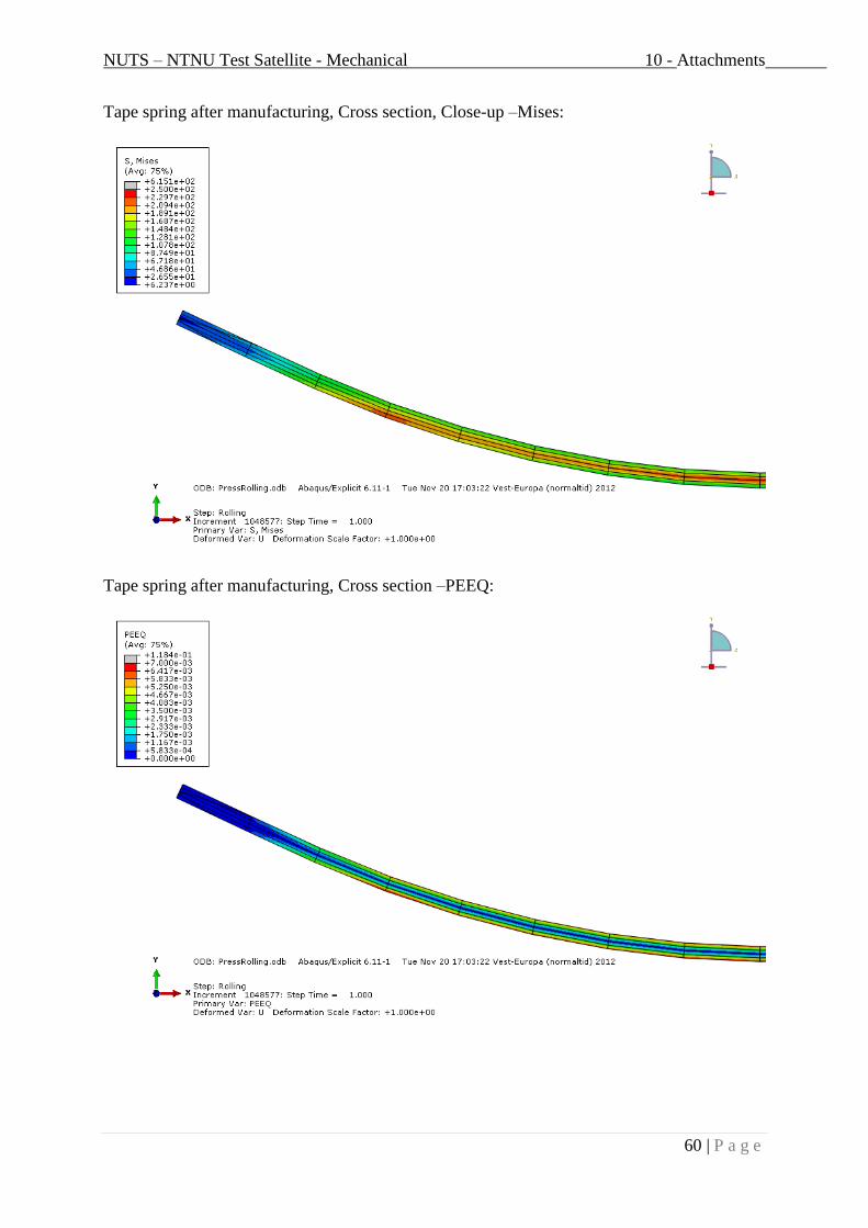
NUTS – NTNU Test Satellite - Mechanical 10 - Attachments
60 | P a g e
Tape spring after manufacturing, Cross section, Close-up –Mises:
Tape spring after manufacturing, Cross section –PEEQ:

NUTS – NTNU Test Satellite - Mechanical 10 - Attachments
61 | P a g e
Tape spring after manufacturing, Cross section –PEEQ:
Tape spring after manufacturing, Cross section, at edges –PEEQ:

NUTS – NTNU Test Satellite - Mechanical 10 - Attachments
62 | P a g e
Tape spring after manufacturing, Cross section, Center –PEEQ:
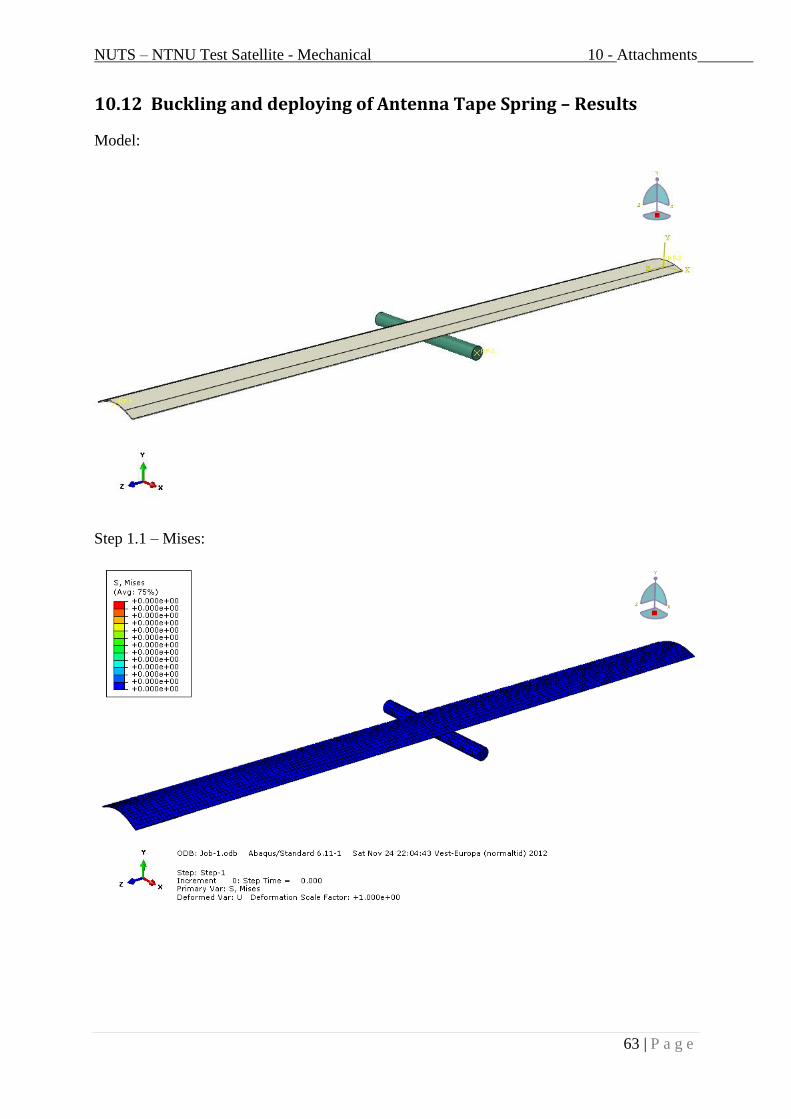
NUTS – NTNU Test Satellite - Mechanical 10 - Attachments
63 | P a g e
10.12 Buckling and deploying of Antenna Tape Spring – Results
Model:
Step 1.1 – Mises:

NUTS – NTNU Test Satellite - Mechanical 10 - Attachments
64 | P a g e
Step 1.2 – Mises:
Step 1.3 – Mises:

NUTS – NTNU Test Satellite - Mechanical 10 - Attachments
65 | P a g e
Step 2.1 – Mises:

NUTS – NTNU Test Satellite - Mechanical 10 - Attachments
66 | P a g e
Step 1 – PEEQ:
Step 2 – PEEQ:

NUTS – NTNU Test Satellite - Mechanical 10 - Attachments
67 | P a g e
10.13 Strength of Antenna Tape Spring – Results
Von Mises stress:
Displacement, y-direction:

NUTS – NTNU Test Satellite - Mechanical 10 - Attachments
68 | P a g e
10.14 FE Analysis of Antenna Tape Spring in Abaqus
10.14.1 Manufacturing of Antenna Tape Spring
10.14.1.1 Drawing the tools

NUTS – NTNU Test Satellite - Mechanical 10 - Attachments
69 | P a g e
10.14.1.1 Drawing the tape spring
10.14.1.2 Inertias of the tools
Insert these values for both she and he press, for an RP defined in each part.
Also convert the she and he press to shell element to be able to mesh them.

NUTS – NTNU Test Satellite - Mechanical 10 - Attachments
70 | P a g e
10.14.1.3 Meshing of parts
Insert these values. Remember explicit, linear, and second-order accuracy.
Mesh the tape spring with at least 4 elements along the thickness, and the tools with finer
mesh than the tape spring.
10.14.1.4 Tape spring material
Assign following material to the tape spring:
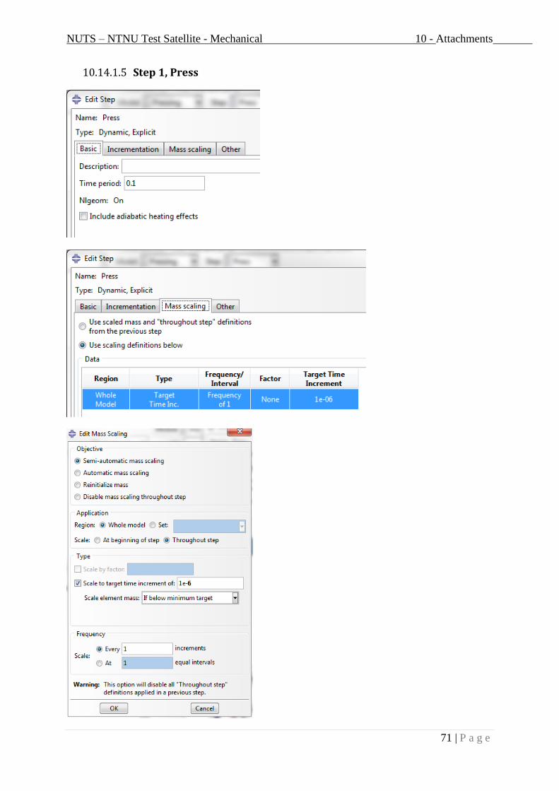
NUTS – NTNU Test Satellite - Mechanical 10 - Attachments
71 | P a g e
10.14.1.5 Step 1, Press
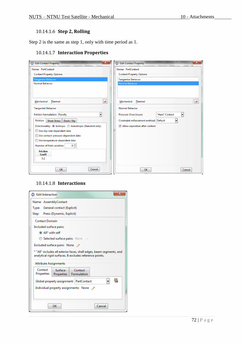
NUTS – NTNU Test Satellite - Mechanical 10 - Attachments
72 | P a g e
10.14.1.6 Step 2, Rolling
Step 2 is the same as step 1, only with time period as 1.
10.14.1.7 Interaction Properties
10.14.1.8 Interactions

NUTS – NTNU Test Satellite - Mechanical 10 - Attachments
73 | P a g e
10.14.1.9 BC HePress
Make a “smooth step” for the displacements amplitude.
10.14.1.10 BC ShePress
10.14.1.11 Job
Make a new job, if multiple processors edit “use multiple processors” below “parallelization”:

NUTS – NTNU Test Satellite - Mechanical 10 - Attachments
74 | P a g e
10.14.2 Buckling and deploying of Antenna Tape Spring
10.14.2.1 Part drawing
Model the corner as discrete rigid, and extrude it 20 mm.
Model the Tape Spring as deformable solid 3D, and extrude it 100 mm.
10.14.2.2 Tape spring material
Assign the following material to the Tape Spring.

NUTS – NTNU Test Satellite - Mechanical 10 - Attachments
75 | P a g e
10.14.2.3 Interaction Properties
10.14.2.4 Interactions

NUTS – NTNU Test Satellite - Mechanical 10 - Attachments
76 | P a g e
10.14.2.5 BC - Tape Spring
10.14.2.6 BC – Corner

NUTS – NTNU Test Satellite - Mechanical 10 - Attachments
77 | P a g e

NUTS – NTNU Test Satellite - Mechanical 10 - Attachments
78 | P a g e
10.14.3 Strength of Antenna Tape Spring
10.14.3.1 Part drawing
Model the Tape Spring as deformable solid 3D, and extrude it 700 mm.
10.14.3.2 Tape spring material
Assign the density of the material and the following material data to the Tape Spring.
10.14.3.3 Loads
Apply gravity load in –y direction in step 1.
10.14.3.4 BS
Fix the Tape Spring end located in origin.