Development of Cloud-Based HILS for Performance...
5
Development of Cloud-Based HILS for Performance Verification of LNGC PMS Junsang Seo 1 , Sangoh Lee 2 , Dukchan Jeon 3 , Jaemun Park 4 , Jun Soo Park 5 , and Kwangkook Lee * 1 Institute of Convergence, USIS Co., Ltd, Ulsan, South Korea 2 Institute of Convergence, USIS Co., Ltd, Ulsan, South Korea 3 Institute of Convergence, USIS Co., Ltd, Ulsan, South Korea 4 Institute of Technology & Research, OSLAB Co., Ltd, Changwon, South Korea 5 Dep’t of Naval Architecture & Ocean IT Engineering, Kyungnam University, Changwon, South Korea * Dep’t of Naval Architecture & Ocean IT Engineering, Kyungnam University, Changwon, South Korea Abstract – A power management system (PMS) has been an important part in a ship integrated control system. To evaluate a PMS for a liquefied natural gas carrier (LNGC), this study proposes a real-time hardware-in-the-loop simulation (HILS), which is composed of major component models such as turbine generator, diesel generator, governor, circuit breaker, and 3-phase loads on MATLAB/Simulink. In addition, a human machine interface (HMI) based on cloud system, real- control console, and main switchboard (MSBD) are constructed in order to develop an efficient control and a similar real environment in an LNGC PMS. More specifically, a comparative study on the performance evaluation of PMS functions is conducted using three test cases for sharing electric power to consumers in an LNGC. The result shows that the proposed system has a high verification capability for the operating function and failure handling evaluation as a PMS HILS. Keywords: Cloud System, HIL (Hardware-in-the-loop), SIL (Software-in-the-loop), PMS (Power Management System), LNGC (Liquefied Natural Gas Carrier) 1 Introduction With the increasing risk in building liquefied natural gas (LNG) vessels, pre-simulation with various scenarios is needed for system integration as well as safe operation. In particular, a power management system (PMS) in a liquefied natural gas carrier (LNGC) is an important part, which operates in tight integration with power control systems to achieve the desired performance and safety. A PMS can control system frequency and voltage as well as the generated real and reactive power [1]. In addition, it usually has a function to prevent breakdown of power generation and power consumption. Failure in the PMS will affect safety and lead to downtime, and may even cause accidents. For these reasons, electrical power management systems have been studied [2 3]. To evaluate the performance of a PMS, there are existing methods such as direct on-site verification and software-based simulation. Among these methods, the direct verification technique evaluates the function of a PMS directly by using analog/digital simulator on real condition. However, it has high physical cost and is risky. On the other hand, results of software-based simulations strongly rely on the model accuracy of power system components, and pure hardware testing lacks flexibility on establishing a complex power system [4]. To solve these problems, hardware-in-the-loop (HIL) simulation is released to enhance the quality of hardware testing. This system reduces the cost of verifying problems such as system malfunction, incorrect calculated configuration parameters, and system errors according to rules and regulations. HIL simulation can provide performance testing, verification, evaluation, development, and diagnosis of electronic equipment solutions [5]. However, domestic shipbuilding companies, which initiate PMS requests to international PMS evaluation agency, pay a high cost because the said companies and the institute of marine equipment research cannot verify it by themselves [6]. To address this problem, this study develops a localized real- time HIL system for marine equipment to evaluate the PMS controller in an LNGC. For operating the HILS, the major components of the LNGC are modeled using MATLAB/Simulink. The power supply model consists of two turbine generators, a diesel generator, and governor. The power consumer model is composed of side thrusters, cargo pumps, ballast water pumps, and lumped loads, which are mostly consumed in an LNGC. These models are operated in NI PXI by using LabVIEW programming to simplify the complexity of HILS. Unlike existing simulators, the proposed methodology can also utilize a control console (CC) and a main switchboard (MSBD) onboard to model a real-ship environment. A method for communicating CC and MSBD is then developed based on the OPC server/client technology through Ethernet communication. To achieve a convenient monitoring system, cloud-based monitoring is implemented on HILS. Furthermore, Int'l Conf. Modeling, Sim. and Vis. Methods | MSV'16 | 31 ISBN: 1-60132-443-X, CSREA Press ©
Transcript of Development of Cloud-Based HILS for Performance...

Development of Cloud-Based HILSfor Performance Verification of LNGC PMS
Junsang Seo1, Sangoh Lee2, Dukchan Jeon3, Jaemun Park4, Jun Soo Park5, and Kwangkook Lee*
1Institute of Convergence, USIS Co., Ltd, Ulsan, South Korea2Institute of Convergence, USIS Co., Ltd, Ulsan, South Korea3Institute of Convergence, USIS Co., Ltd, Ulsan, South Korea
4Institute of Technology & Research, OSLAB Co., Ltd, Changwon, South Korea5Dep’t of Naval Architecture & Ocean IT Engineering, Kyungnam University, Changwon, South Korea*Dep’t of Naval Architecture & Ocean IT Engineering, Kyungnam University, Changwon, South Korea
Abstract – A power management system (PMS) has been an important part in a ship integrated control system. To evaluate a PMS for a liquefied natural gas carrier (LNGC), this study proposes a real-time hardware-in-the-loop simulation (HILS), which is composed of major component models such as turbine generator, diesel generator, governor, circuit breaker,and 3-phase loads on MATLAB/Simulink. In addition, ahuman machine interface (HMI) based on cloud system, real-control console, and main switchboard (MSBD) are constructed in order to develop an efficient control and asimilar real environment in an LNGC PMS. More specifically, a comparative study on the performance evaluation of PMS functions is conducted using three test cases for sharing electric power to consumers in an LNGC. The result shows that the proposed system has a high verification capability for the operating function and failure handling evaluation as a PMS HILS.
Keywords: Cloud System, HIL (Hardware-in-the-loop), SIL(Software-in-the-loop), PMS (Power Management System), LNGC (Liquefied Natural Gas Carrier)
1 IntroductionWith the increasing risk in building liquefied natural gas
(LNG) vessels, pre-simulation with various scenarios is needed for system integration as well as safe operation. In particular, a power management system (PMS) in a liquefied natural gas carrier (LNGC) is an important part, which operates in tight integration with power control systems to achieve the desired performance and safety. A PMS can control system frequency and voltage as well as the generated real and reactive power [1]. In addition, it usually has afunction to prevent breakdown of power generation and power consumption. Failure in the PMS will affect safety and lead to downtime, and may even cause accidents. For these reasons,electrical power management systems have been studied [23].
To evaluate the performance of a PMS, there are existing methods such as direct on-site verification and software-basedsimulation. Among these methods, the direct verification technique evaluates the function of a PMS directly by using analog/digital simulator on real condition. However, it hashigh physical cost and is risky. On the other hand, results of software-based simulations strongly rely on the model accuracy of power system components, and pure hardware testing lacks flexibility on establishing a complex power system [4].
To solve these problems, hardware-in-the-loop (HIL) simulation is released to enhance the quality of hardware testing. This system reduces the cost of verifying problems such as system malfunction, incorrect calculated configuration parameters, and system errors according to rules and regulations. HIL simulation can provide performance testing, verification, evaluation, development, and diagnosis of electronic equipment solutions [5]. However, domestic shipbuilding companies, which initiate PMS requests to international PMS evaluation agency, pay a high cost because the said companies and the institute of marine equipment research cannot verify it by themselves [6].
To address this problem, this study develops a localized real-time HIL system for marine equipment to evaluate the PMS controller in an LNGC. For operating the HILS, the major components of the LNGC are modeled using MATLAB/Simulink. The power supply model consists of two turbine generators, a diesel generator, and governor. The power consumer model is composed of side thrusters, cargopumps, ballast water pumps, and lumped loads, which aremostly consumed in an LNGC.
These models are operated in NI PXI by using LabVIEW programming to simplify the complexity of HILS. Unlike existing simulators, the proposed methodology can also utilizea control console (CC) and a main switchboard (MSBD)onboard to model a real-ship environment. A method for communicating CC and MSBD is then developed based on the OPC server/client technology through Ethernet communication. To achieve a convenient monitoring system,cloud-based monitoring is implemented on HILS. Furthermore,
Int'l Conf. Modeling, Sim. and Vis. Methods | MSV'16 | 31
ISBN: 1-60132-443-X, CSREA Press ©

this system uses load sharing test cases for evaluating PMS functions with the proposed HIL test bed.
The rest of the paper is organized as follows. Section 2includes the necessary background information about PMS roles in an LNGC and the standard SIL/HIL system. Section 3introduces our proposed configuration of PMS HILframework. Section 4 presents the experimental results, and the conclusions are provided in Section 5.
2 Background Information2.1 Power Management System in LNGC
The term “power management system” was used before to describe procedures for the automatic starting and stopping of electrical generators to meet actual load requirements.However, it is now applied to a very wide range of control systems, even including what really are “energy management systems” [7].
A PMS in an LNGC is a programmable logic controller for high voltage (HV) and low voltage (LV) switchboards, generators, and prime mover control. The system operates the normal functions necessary to manage the diesel and turbinegenerators in order to balance power generation and power consumption. The PMS is interfaced with HV main switchboards, HV main cargo switchboards, and LVswitchboards through hardwire (digital inputs or outputs and analog inputs) or Ethernet cable.
2.2 HIL (Hardware-in-the-loop)Hardware-in-the-loop (HIL) simulation is a technique that is
used for developing and testing complex real-time embedded systems. HIL simulation provides an effective platform by adding the complexity of the plant under control to the test platform. The complexity of the plant under control is included in the test and development by adding a mathematical representation of all related dynamic systems [8].In particular, HIL simulation has high expandability to apply to embedded systems in vehicles, aircrafts, vessels, and on/offshore plants.
Figure 1. HILS Structure for Ship Management System
In shipbuilding and on/offshore plant fields, HILS is used for drilling operation control, power generation/distribution, and dynamic positioning. Marine Cybernetics provides services about SILS/HILS solutions in marine engineering since 2002. This service can reduce the enormous cost under a number of incidents caused by partial and complete blackout.
Figure 1 shows the HIL simulation structure for ship management system. HILS consists of human machine interface (HMI), process control network, data acquisition & control, plant equipment simulation, and simulation control part. Generally, HIL simulation that applies various fields has to develop equipment simulation and simulation control.
3 Configuration of PMS HIL Testing Bed3.1 Simulation Model
The proposed power simulation model consists of a power supply and power consumer to operate two turbine generators,diesel generators, bow thrusters, cargo pumps, ballast pumps,and lumped loads in the LNGC. The specifications of the diesel and turbine generators are described in Table 1. In addition, the specific information of the power consumer is listed in Table 2.
Table 1. Specification of Diesel and Turbine Generator
Diesel and Turbine GeneratorMax Power 3.45 MWVoltage 6,600 VFrequency 60 Hz
Table 2. Specification of Power Consumer
Max Power(kW)
Voltage(V)
Frequency(Hz)
Bow Thruster 1,800 6,600 60Cargo Pump 530 6,600 60Ballast Pump 330 6,600 60Lumped Load 1,000 440 60
Figure 2 presents the overall circuit of the power plant simulation models by using MATLAB/Simulink. Thesemodels are implemented by SimPowerSys libraries, which provide power model library for easy modeling.
Figure 2. Overall Circuit of Power Supply and Power Consumer on MATLAB/Simulink
32 Int'l Conf. Modeling, Sim. and Vis. Methods | MSV'16 |
ISBN: 1-60132-443-X, CSREA Press ©
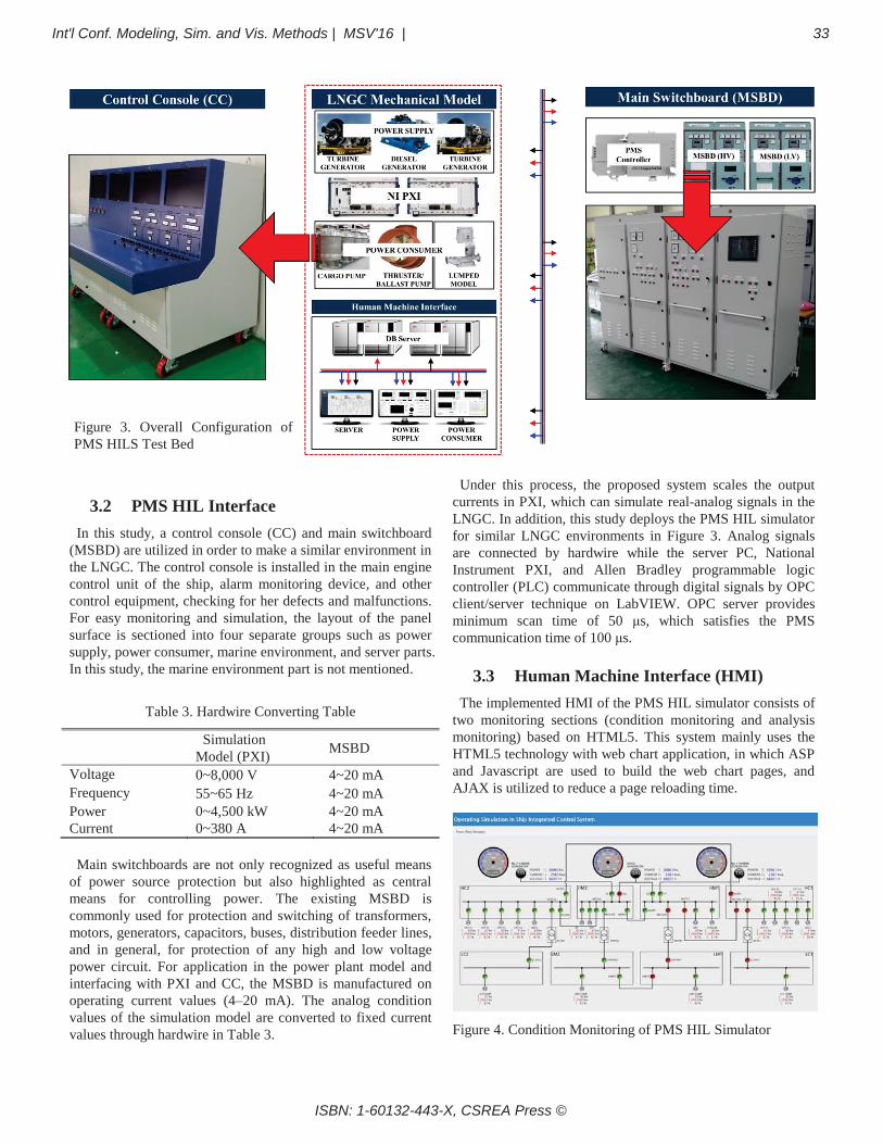
3.2 PMS HIL InterfaceIn this study, a control console (CC) and main switchboard
(MSBD) are utilized in order to make a similar environment in the LNGC. The control console is installed in the main engine control unit of the ship, alarm monitoring device, and other control equipment, checking for her defects and malfunctions.For easy monitoring and simulation, the layout of the panel surface is sectioned into four separate groups such as power supply, power consumer, marine environment, and server parts.In this study, the marine environment part is not mentioned.
Table 3. Hardwire Converting Table
Simulation Model (PXI) MSBD
Voltage 0~8,000 V 4~20 mAFrequency 55~65 Hz 4~20 mAPower 0~4,500 kW 4~20 mACurrent 0~380 A 4~20 mA
Main switchboards are not only recognized as useful means of power source protection but also highlighted as central means for controlling power. The existing MSBD iscommonly used for protection and switching of transformers, motors, generators, capacitors, buses, distribution feeder lines,and in general, for protection of any high and low voltage power circuit. For application in the power plant model and interfacing with PXI and CC, the MSBD is manufactured on operating current values (4–20 mA). The analog condition values of the simulation model are converted to fixed current values through hardwire in Table 3.
Under this process, the proposed system scales the output currents in PXI, which can simulate real-analog signals in the LNGC. In addition, this study deploys the PMS HIL simulator for similar LNGC environments in Figure 3. Analog signalsare connected by hardwire while the server PC, NationalInstrument PXI, and Allen Bradley programmable logic controller (PLC) communicate through digital signals by OPC client/server technique on LabVIEW. OPC server providesminimum scan time of 50 μs, which satisfies the PMScommunication time of 100 μs.
3.3 Human Machine Interface (HMI)The implemented HMI of the PMS HIL simulator consists of
two monitoring sections (condition monitoring and analysis monitoring) based on HTML5. This system mainly uses the HTML5 technology with web chart application, in which ASP and Javascript are used to build the web chart pages, and AJAX is utilized to reduce a page reloading time.
Figure 4. Condition Monitoring of PMS HIL Simulator
Figure 3. Overall Configuration of PMS HILS Test Bed
Int'l Conf. Modeling, Sim. and Vis. Methods | MSV'16 | 33
ISBN: 1-60132-443-X, CSREA Press ©

The first section is condition monitoring, which includes output values (circuit breaker condition, power, current, andvoltage by power supply and consumer) shown in Figure 4.The HMI is connected to the programmable power equipment models in PXI with two types of signal: double type signal and Boolean signal. Double type signals are output values of the power supply and power consumer, and circuit breaker condition values are presented as Boolean type signals. Communication is achieved using Modbus TCP under a speed of 100 μs.
Figure 5. Analytical Monitoring of PMS HIL Simulator
The other section is analytical monitoring, which can analyze circuit condition values using the speed control function according to test cases. In Figure 5, this web page can evaluate a specific condition at current or previous time, unlike in real-time environment where a user cannot identify the time passed windows. In addition, if we need a detailed analysis when an unexpected occurrence and sudden situation are generated, it easily finds the specific condition and situation.
4 Experimental ResultsTo evaluate the PMS, an actual test is carried out under the
PMS HIL simulation environment. The proposed HIL simulator is verified with the functional specification of the PMS. The performance verification between the powergenerator control and the PMS is to be confirmed through load sharing test, governor test, and parallel running test. Among these test cases, load sharing is the fundamental and most critical part for evaluating the entire functionality of the PMS. Therefore, this study performs a load sharing test as the main function of the PMS. Load sharing is classified into symmetric, asymmetric, and fixed load sharing.
4.1 Symmetric Load SharingIn symmetric load sharing mode, the loads of generators
running in parallel have to be equal within a small dead band (±3%) of rated power. As shown in Table 4, the experimental results present a similar condition, which generates total power (5775 kW).
Table 4. Result of Symmetric Load Sharing
Item Conditions Result
Symmetric load sharing
- Power Consumer:5,775 kW
- TG1: 1,925 kW- TG2: 1,925 kW- DG: 1,925 kW- Dead band:±3% of rated power
- Power Consumer:5,775 kW- TG1: 1,931 kW- TG2: 1,931 kW- DG: 1,913 kW
Satisfied
4.2 Asymmetric load sharingAsymmetric load sharing mode evaluates the operating
functions of three generators; the selected generator (master)is loaded to 80% while the other generators (slave) will share the load. In this study, test conditions are selected as follows: Three generators are operated as TG1 (master), TG2 (off), DG (slave), and the total load is 4729 kW, including a side thruster (1,800 kW), three cargo pumps (each 530 kW), a ballast pump (330 kW), and a ship lumped load (1,000 kW).
If TG1 is changed in order to supply the remaining power to consumers in asymmetric load sharing mode, DG will be also changed automatically to master. If a non-slave generator takes heavy load (90%) or light load (20%), a master generator will increase/decrease its power respectively, to prevent overload or reverse power on the non-selected generator. Figure 6 demonstrates the same results that Table 5provides in the PMS under asymmetric load sharing test condition.
Table 5. Result of Asymmetric Load Sharing (TG1 or TG2)
Item Conditions Result
Asymmetric load sharing
- Power Consumer:4,720 kW - TG1:2,760 kW (80%)- TG2: OFF- DG: 1,960 kW- Dead band:±3% of rated power
- Power Consumer: 4,746 kW- TG1: 2,754 kW- TG2: OFF- DG: 1,992 kW
Satisfied
Figure 6. Result of Asymmetric Load Sharing in PMS
34 Int'l Conf. Modeling, Sim. and Vis. Methods | MSV'16 |
ISBN: 1-60132-443-X, CSREA Press ©

4.3 Fixed load sharingTo maintain the load sharing function of the selected
generator, it is possible to choose a generator in steady load. This mode cannot be selected when the generator is in standby mode or when it is only one generator online. If a non-selected generator takes heavy load (90%) or light load (20%), a selected generator will increase/decrease its power respectively to protect the dangerous situation when the non-selected generator is faced with overload or reverse powercondition.
The test condition is similar to asymmetric load sharing when the percentage of TG1’s total power is set to 70%. Figure 7 demonstrates the same results that Table 6 provides in the PMS under fixed load sharing test condition.
Table 6. Result of Fixed Load Sharing (TG1 or TG2)
Item Conditions Result
Fixed load sharing
- Power Consumer:4,720 kW
- TG1: 2,415 kW (70%)- TG2: OFF- DG: 2,304 kW- Dead band : ±3%
- Power Consumer: 4,735 kW - TG1: 2,426 kW- TG2: OFF- DG: 2,309 kW
Satisfied
Figure 7. Result of Fixed Load Sharing in PMS
5 ConclusionsHIL is an important solution to evaluate a PMS for an LNGC,
and it is one of the most well-known evaluation techniquesthat is used in various fields. However, domestic shipbuilding companies and the institute of marine equipment research cannot evaluate PMS HIL by themselves. To address this issue, this study proposed a PMS HIL simulator, which is configured with power supply/consumer models, CC, MSBD, and HMI. The proposed HIL simulation platform used real-equipment data in marine industry in order to make a similar LNGC environment.
In addition, this study utilized load sharing test cases of aPMS. Comparative testing results indicate that the proposed system shows a great potential for symmetric, asymmetric, and
fixed load sharing. To make it more useful, various PMS test cases will be evaluated under the proposed PMS HIL simulator. In addition, further system developments will still be required for ship automation from PMS control as well as energy management system in future works.
AcknowledgmentThis research was supported by National IT Industry Promotion Agency (Grants No. S0170-15-1078) and Business for Cooperative R&D between Industry, Academy, and Research Institute funded Korea Small and Medium Business Administration (Grants No. C0333413) in 2016. All of the support is gratefully acknowledged.
6 References[1] Parizad, A., “Dynamic stability analysis for Damavandpower plant considering PMS functions by DIgSILENTsoftware”, Environment and Electrical Engineering (EEEIC), 2013
[2] X. J. Tang, T. Wang, C. Zhi, and Y. M. Huang, "The design of power management system for solar ship",Transportation Information and Safety, 2015
[3] S. V. Giannoutsos and S. N. Manias, “Energy management and D/G fuel consumption optimization in the power system of marine vessels through VFD-based process flow control”, Environment and Electrical Engineering, 2015
[4] Yu Zhou, Jin Lin, Younghua Song, Yu Cai, Hao Liu, “A power hardware-in-loop based testing bed for auxiliary active power control of wind power plants”, Electric Power Systems Research, 2015
[5] H Huang, M Pan, Z Lu, “Hardware-in-the-loop simulation technology of wide-band radar targets based on scattering center model”, Chinese Journal of Aeronautics, 2015
[6] Parizad A., “Requirement analysis and architecture establishment for PMS FMEA simulator based on SILS”, Proceedings of the Annual Autumn Conference, 2014
[7] Wikipedia, the free encyclopedia, “Hardware-in-the-loop simulation”, 2016
Int'l Conf. Modeling, Sim. and Vis. Methods | MSV'16 | 35
ISBN: 1-60132-443-X, CSREA Press ©