Development of biomass gasification system based on .... U. Lee.pdf · Development of biomass...
34
Development of biomass gasification system based on fluidized bed technologies Uen Do Lee and Won Yang Energy system R&D group Korea Institute of Industrial Technology (KITECH)
Transcript of Development of biomass gasification system based on .... U. Lee.pdf · Development of biomass...

Development of biomass gasification system based on fluidized bed
technologies
Uen Do Lee and Won Yang
Energy system R&D group
Korea Institute of Industrial Technology (KITECH)

Korea Institute of Industrial Technology

Korea Institute of Industrial Technology

Energy System R&D Group
• 10 Principal researchers, 2 Senior researchers, 20 researchers• Research areas
Low-CarbonCombustion in PowerGen
System
Renewablefuel
conversion
IndustrialCombustion
HVAC system
• Oxy-fuel combustion for CO2 capture• Co-firing of renewable fuels in boilers• Management of coal power generation system• Flue-gas treatment system• Combustion diagnostics in thermal power plant
• Fluidized bed gasification (BFB/CFB/DFB) • Stoker and rotary kiln reactors• Pyrolysis: Torrefaction, Carbonization• Syngas & bio-oil utilization
• Low NOx burners for industrial boilers• low NOx combustion system• Melting furnace with combustion system• Clean combustion in engines
• Heat exchanger• Refrigeration system• Turbo-machinery• Renewable heat: Solar heat, geothermal

Related Projects in KITECH

Biomass co-combustion in a conventional boiler:
<TGA tester > <Tube Furnace >
EFB Pellet
<Furnace Test>
Woody biomass EFB
<FB reactor><Ash melting tester>
<Combustion Test>
(C)
(O)
EFB (INA)
<Ash melting test>
Waste/Biomass conversion
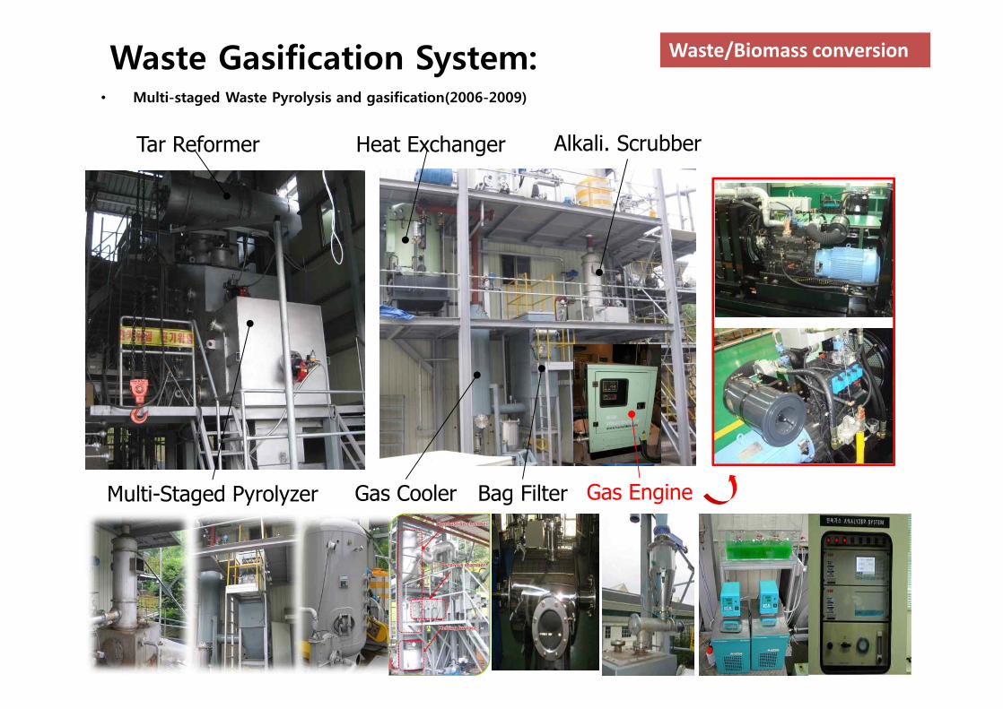
Waste Gasification System:• Multi-staged Waste Pyrolysis and gasification(2006-2009)
Waste/Biomass conversion
Tar Reformer
Multi-Staged Pyrolyzer
Heat Exchanger Alkali. Scrubber
Gas Cooler Bag Filter Gas Engine

BFB gasifier (KITECH):
SEI ISU EPI KITECH
Type BFB BFB BFB BFB
Fuel Wood Corn Wood Wood
Method Air Air Air Air
Temp (℃) 650~815 730 650 650~800
CO 15.5 23.9 17.5 16.1
H2 12.7 4.1 5.8 16.5
CO2 15.9 12.8 15.8 16.4
CH4 5.72 3.1 4.65 5.3
H2O dry dry dry dry
H2/CO 0.8 0.2 0.3 1.02
0 10 20 30 400
4
8
12
16
20
0 10 20 30 400
2
4
6
8
10
12
14
16
18
20
Elec
tronic
Pow
er(k
We)
Conc
entra
tion(
vol.%
)
H2
CO2
CO CH4
Electronic Power
Time(min)
Waste/Biomass conversion

CFB biomass gasifier (Gwang-Yang):
1. Combustor2. Gasifier3. Lower loopseal4. Upper loopseal5. Cyclone
1
23
2
4
5
6
Feedstock Woody biomass
Capacity 3 MWth
DimensionGasifier 1.0m(W)×1.5m(L)×2.5m(H)
Combustor φ0.4m×17.5m
Fluidization velocity
Gasifier 0.3-0.5 m/s (3-5 Umf)
Combustor 4-5 m/s
Bed material Silica sand, 380㎛
Dimensionless Velocity Ratio, ucomb/ut (m/s)
1 3 5 7 90 2 4 6 8 10
Solid
s C
ircul
atio
n R
ate,
Gs(k
g/m
2 s)
0
5
10
15
20
25
30
35
ChockingAbove ut
confidential
Designed by KITECHInternational collaborative project with CUT, Sweden
Waste/Biomass conversion

Biomass Gasification for BTL:
• Biomass gasification with a dual fluidized bed (2007~2012)– Can produce high-valued fuels such as
• Bio-diesel• Bio-SNG(Synthetic natural gas)• Bio-hydrogen
– Biomass gasification with syngas cleaning for F-T process– Scale: 1 ton/day
< Schematic diagram of BTL project >< 1ton/day Biomass Gasifier >
Waste/Biomass conversion

Oxygen enhanced BFB gasifier for RDF:
Feeding system for RDF
Feeding test result
Airintake
Hot water output
Exhaustgases
Waste/Biomass conversion

Re-gasification system for low rank oil :
Used cooking oilCooking oil
Pyrolysis oil/Byproducts
Used engine oil Coal water slurry
Fuel + Air
Waste/Biomass conversion

Gasification of byproduct from black liquor bio-refinery:
Fermentation(5C)
pH = 5.6
KraftPulping
BlackLiquor
Hydrolysisand
Filtration
Limingand
Filtration
Bioethanol
Pulp
WoodChip
Acetic acid
Formic acid
CaO
CaSO4
H2SO4enzyme
Solvent
Salt Residues
80g/LSugar
RecoveryBoiler
Green LiquorGreen Liquor
SmeltWeakwash
NaSO4
ElectricitySteam
Lignin
Gasification (H2, Co)
Electricitysteam
Waste/Biomass conversion
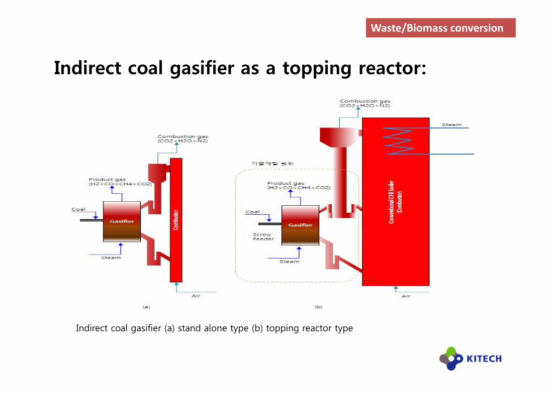
Indirect coal gasifier as a topping reactor:
Indirect coal gasifier (a) stand alone type (b) topping reactor type
Waste/Biomass conversion

Development of indirect biomass gasifier for BTL process

Biomass To Liquid (BTL) Process:
Wood(Biomass)
1 Tonwood
GasificationFischer-Tropsch
Synthesis
Biosyngas240 L
FT Wax210 L
BTL-Diesel
LightFT Product
Electricity & Heatfrom off-gas

Project details:v Biomass gasification including gas cleaning and biomass-to-liquid (BTL) with F-T process
v BFB gasification: H2/CO > 1, cold gas efficiency > 60%, gas cleaning for F-T process
v Biomass 1 t/d, Biodiesel 0.1 bbl/d (2010) à Biomass 1t/day, 1 bbl/d (2012)à 30-1000 bbl/d commercial plant
Sand + Char
Hot Sand
SteamMinimized O2
Raw material<Water contents<10%>
Low temperatureDrying(<120℃)
Solid-liquid separation
Hydrothermal reaction(250℃, <30 atm)
F-T process
Separation
Upgrading
BTL-Diesel
Woody Biomass
Feeder
BFB Gasifier FFB Combustor
Exhaust gasHeat exchanger Water
Minimized Tar Cracker
Scrubber & Filter
SyngasWGSR CO2 Remover
< Schematic diagram of ETI project >
KITECH
KIER
KRICT

Previous Researches on BTL Process:

Gasifier
Combustor
AirSteam
Flue gas
Heated sand
Sand,char
Product gas(CH₄, CO, H₂, CO₂)
Lower loop seal
Upper loop seal
Cyclone
Biomass Biomass
Hydrodynamics of DFB
* Simulation result from Barracuda
Dual Fluidized Bed Gasifier:

Development History:10kWth pilot plant 100kWth pilot plant 8MWth CHP Plant
Gussing8MWth CHP Plant
Oberwart14MWth CHP Plant
Seden
1993-1996 1995-1999 2003-2011 2008-now 2012
20kWth pilotPlant
200kWth pilot plant without gas cleaning system
200kWth pilot plant 3.2MWth Pilot plant(planned)
10MWth commercialplant(planned)
2007-2009 2009-2011 2011-2012 2013-2015 2015-2018

Long-term operation test with small BTL system:
20kW bench scale DFB gasifier for BTL
gasifier & 1st clesning process
syngas compressor & 2nd clesning process & FT reactor
□ Iron based FT catalyst - Productivity: C5+>150g/L-cat-h)- Rate of conversion: > 90%
□ 0.1 BPD FT reactor test (Fixed bed)
□ Catalyst life time > 2000 hours
■ FT catalyst
Iron Based FT catalyst (KRITC)

Long Term Operation of 20kW BTL Process:
Sampling pointSulfur components (ppmV)
H2S COS
SP-1 18 1.2
SP-2 0.5 1.2
SP-4 b.d. b.d.

200kW DFB Biomass Gasifier:

Syngas Cleaning System:

2nd cleaning process<MeOH absorption tower for acid gas removal>
1 bbl/day Fischer-Tropsch reactor
Gasifier
Combustor
Bucket Elev. Biomass hopper Biomass Feeder
1st cleaning process & syngas compressor
200kW DFB Biomass Gasifier:

Operation time (day)
0 5 10 15 20
Gas
com
posit
ion
(dry
vol
. %)
0
10
20
30
40
50 CO CO2 H2 CH4 O2
Tem
pera
ture
(o C)
600
700
800
900
1000
1100 Gasifier_bed Gasifier_freeboard Combustor_outlet
Long term operation results (Upper: temperature, Lower: syngas compositions) Average syngas composition
Gas Composition (vol %)
CO 21.3
CO2 19.0
CH4 10.0
H2 35.0
CnHm n.a.
H2/CO mole ratio 1.64
Gas yield (Nm3/kg of raw
biomass)>1.1
Lower heating value
(MJ/Nm3)>10.0
Cold gas efficiency(Ceff, %) >61.2
Long term operation results of BTL system:

Performance of KITECH DFB gasifier:
Mid Sweden Univ.(MIUN)*
150kW
Güssing*FICFB(8MW)
Chalmers*2-4MW
Univ. of Canterbury
100kW**
KITECH200kW
Gasifier Type DFB DFB DFB DFB DFB
Fuel WoodPellets
BiomassChips
Wood Chips/Pellets
Wood Chips/Pellets Pellets
Bed material Silica sand Olivine Silica Sand Silica sand/Olivine Silica Sand
Gasifying agent/Oxidizer Steam/Air Steam/Air Steam/Air Steam/Air Steam/Air
Temperature(℃) 800 850~900 780~830 642~753 766
H2 50.9 36~42 18.74~27 15~30 34.0
CO 29.6 19~24 26.9~33.3 28~40 20.4
CO2 12.6 20~25 14.6~18.3 13~21 18.6
CH4 9.5 9~12 11.1-11.7 9~15 9.8
H2/CO 1.7 1.8~1.9 0.7-0.8 0.78~1 1.7
*Data of the representative DFB gasifiers were adopted from the reference [Göransson, K. et al., 2011]** Data of the University of Canterbury, New Zealand [Bull, D. et al., 2009]

Characteristics of BTL fuel:
Direct photo of synthesis BTL fuels
BTL Diesel(170℃~320℃)
BTL Gasoline(60℃~170℃)
Courtesy of KRITC/KPETRO
Carbon number distribution of the hydrocarbon liquid produced in the FT reactor

Characteristics of BTL fuel:
min0 1 2 3 4 5 6 7 8 9
pA
0
200
400
600
800
1000
1200
FID1 A, Front Signal (20110414\20110414 2011-04-14 10-05-16\SIG010000001.D)
F-T Diesel(replicate gas)
min0 1 2 3 4 5 6 7 8
pA
0
100
200
300
400
500
600
700
800
900
FID1 A, Front Signal (20110117\20110117 2011-01-17 17-52-19\P_O50_2.D)
min0 1 2 3 4 5 6 7 8
pA
0
100
200
300
400
500
600
FID1 A, Front Signal (20110125\20110125 2011-01-25 16-07-30\DIESEL.D)
Diesel(winter)
Kerosene
min0 1 2 3 4 5 6 7 8
pA
0
100
200
300
400
500
600
700
FID1 A, Front Signal (20110727\20110728 2011-08-03 13-44-23\020F0101.D)
< 0
.010
< 2
.830
< 2
.831
< 2
.833
< 5
.575
< 5
.579
< 5
.580
< 9
.000BTL Diesel
Courtesy of KRITC/KPETRO

Comparison of conventional diesel and BTL diesel:
Test ItemsUnits Standard Diesel BTL diesel(100%)
℃ < 0.0 / < -17.5 (winter) -35.0 -22.5
Flow point ℃ - -4.0 -17.0
Cloud point ℃ Ø 40 44 50
Flash point mm2/s 1.9 ~ 5.5 - -
Dynamic viscosity ℃ - 150 171
Boiling
Initial ℃ - 172 190
10% ℃ - 243 232
50% ℃ < 360 334 290
90% ℃ - 367 312
Final wt% < 0.15 < 0.15 < 0.15
Residual carbon vol% < 0.02 < 0.01 < 0.01
Courtesy of KRITC/KPETRO
Test items Units Standard Diesel BTL diesel(100%)
Sulfur mg/kg < 10 6.4 1.7
Ash wt% < 0.02 < 0.01 < 0.01
Cetane number -> 52
> 48 (winter)51.9 68.6
Induced Cetane number - - 49.4 54.6
Corrosion - < 1 < 1 < 1
Filter clogging℃ < -16 -33.0 -17.0
Lubrication(HFRR wear)
μm < 400 234 438
Density kg/m3 815 ~ 835 817 779
Poly-aromatics wt% < 5 1.0 0.2
Aromatics wt% < 30 18.7 4.1

Test car/engine details
Performance test equipment with dynamometer
< Courtesy of KPETRO>
Model Odometer Engine Type Injection Type
Santafe (2010) 72,593D engine
(2,200 cc)CRDI
Engine performance test:

Original diesel fuel vs BTLD30
CO THC
NOx PM
Diesel BTL D300.0
0.1
0.2
0.3
0.4
0.5
Test fuel
CO
emis
sion
(g/k
m)
Diesel BTL D300.00
0.01
0.02
0.03
0.04
0.05
0.06
0.07
Test fuel
THC
emis
sion
(g/k
m)
Diesel BTL D300.0
0.1
0.2
0.3
0.4
0.5
Test fuel
NOx
em
issi
on(g
/km
)
Diesel BTL D300.00
0.01
0.02
0.03
0.04
0.05
Test fuel
PM e
mis
sion
(g/k
m)
Emission test results of BTL(30%)+Diesel fuel(70%):

Summary
1. Syngas composition and H2/CO ratio are suitable for F-T process and the
performance of DFB biomass gasifier was verified with the long-term
operation test over 500 hours.
2. In DFB system, tar reduction and increase of steam conversion rate are
the key technologies for increasing gasification efficiency.
3. As an alternative fuel, BTL diesel is almost sulfur free and has low
aromatic content and high Cetane number.
4. For low temperature characteristics, density and lubrication are the main
issues.
5. It was found that the mixture of BTL and conventional diesel reduces
engine emissions.

Thank you for your attention