Development of a PM-Generator for a Counter-Rotating Micro ...
6
Abstract -- Nowadays, a great effort is done to find new alternative renewable energy sources to replace part of nuclear energy production. In this context, this paper presents a new axial counter-rotating turbine for small-hydro applications which is developed to recover the energy lost in release valves of water supply. The design of the two PM- generators, their mechanical integration in a bulb placed into the water conduit and the AC-DC Vienna converter developed for these turbines are presented. The sensorless regulation of the two generators is also briefly discussed. Finally, measurements done on the 2-kW prototype are analyzed and compared with the simulation. Index Terms--Generators, Hydroelectric power generation, Permanent magnet machines, Sensorless control, Variable speed drives. I. NOMENCLATURE 2p Number of poles (-) k u Back EMF constant line voltage ( V/(rad/s)) k w Winding factor (-) lact Active length of the motor (m) L d Motor synchronous inductance (H) m Number of phases (-) n Motor speed (t/s) N Number of turns in series per phase (-) P el Electrical recovered power (W) P h Hydraulic power (W) P mec Mechanical power (W) Q Number of slots (-) q Number of slot per pole and phase (-) Q w Water flow (m 3 /s) R ph Stator phase resistance () p Pressure difference (N/m 2 ) e Equivalent air gap (m) Motor speed (rad/s) p Pole pitch (m) II. INTRODUCTION HIS paper presents the electromechanical part of an axial micro-turbine developed in collaboration between the Laboratory of hydraulic machines LMH, Swiss Federal Institute of Technology (EPFL) and the Institute of Systems Engineering, University of Applied Sciences Western Valais (HES SO Valais). The prediction of hydraulic efficiency of the turbine using numerical simulation of the flow is discussed in detail in [1], [2]. For this one-stage design, two counter rotating runners compose the turbine: a five-blade runner and a seven-blade The investigation reported in this paper is part of the work carried out for the HYDRO VS project whose partners are the HES SO Valais and the EPFL. This project is financially supported by the Ark Energy.. J D. Melly, R. Horta, C. Münch, H. Biner, S. Chevailler are with the institute of Systems Engineering, University of Applied Sciences Western Switzerland, HES-SO, 1950 Sion ([email protected]) runner. This type of new turbine allows an axial turbomachine to work in “high-head” operating conditions where Pelton turbines are usually used. The two counter rotating turbines can rotate with different absolute speeds and therefore they have to be driven separately. This design with two PM-generators differs from the counter rotating rotors presented in [3], where only one machine was needed to rotate the counter rotating propellers of a ship. The turbine with its two counter- rotating runners and the scheme of the application are shown in Fig. 1. Fig. 1. Counter rotating turbine with its two runners and the energy recovery scheme of the two generators of the counter-rotating micro-Hydro turbine. This paper focuses on the electric parts of this new turbine and more particularly on the generator design and the regulation of the system. In such an application, the electrical machine can be either mounted inside the water conduit (bulb-version) or around the conduit (Straflo- version [4], [5]). Advantages and drawbacks of these two topologies are summarized in Table I. Development of a PM-Generator for a Counter- Rotating Micro-Hydro Turbine D. Melly, R. Horta, C. Münch, H. Biner, S. Chevailler T 978-1-4799-4389-0/14/$31.00 ©2014 IEEE 124
Transcript of Development of a PM-Generator for a Counter-Rotating Micro ...
Abstract -- Nowadays, a great effort is done to find new alternative renewable energy sources to replace part of nuclear energy production. In this context, this paper presents a new axial counter-rotating turbine for small-hydro applications which is developed to recover the energy lost in release valves of water supply. The design of the two PM-generators, their mechanical integration in a bulb placed into the water conduit and the AC-DC Vienna converter developed for these turbines are presented. The sensorless regulation of the two generators is also briefly discussed. Finally, measurements done on the 2-kW prototype are analyzed and compared with the simulation.
Index Terms--Generators, Hydroelectric power generation, Permanent magnet machines, Sensorless control, Variable speed drives.
I. NOMENCLATURE
2p Number of poles (-) ku Back EMF constant line voltage ( V/(rad/s)) kw Winding factor (-) lact Active length of the motor (m) Ld Motor synchronous inductance (H) m Number of phases (-) n Motor speed (t/s) N Number of turns in series per phase (-) Pel Electrical recovered power (W) Ph Hydraulic power (W) Pmec Mechanical power (W) Q Number of slots (-) q Number of slot per pole and phase (-) Qw Water flow (m3/s) Rph Stator phase resistance () p Pressure difference (N/m2) e Equivalent air gap (m) Motor speed (rad/s) p Pole pitch (m)
II. INTRODUCTION
HIS paper presents the electromechanical part of an axial micro-turbine developed in collaboration between the Laboratory of hydraulic machines LMH, Swiss
Federal Institute of Technology (EPFL) and the Institute of Systems Engineering, University of Applied Sciences Western Valais (HES SO Valais). The prediction of hydraulic efficiency of the turbine using numerical simulation of the flow is discussed in detail in [1], [2]. For this one-stage design, two counter rotating runners compose the turbine: a five-blade runner and a seven-blade
The investigation reported in this paper is part of the work carried out
for the HYDRO VS project whose partners are the HES SO Valais and the EPFL. This project is financially supported by the Ark Energy..
J D. Melly, R. Horta, C. Münch, H. Biner, S. Chevailler are with the
institute of Systems Engineering, University of Applied Sciences Western Switzerland, HES-SO, 1950 Sion ([email protected])
runner. This type of new turbine allows an axial turbomachine to work in “high-head” operating conditions where Pelton turbines are usually used. The two counter rotating turbines can rotate with different absolute speeds and therefore they have to be driven separately. This design with two PM-generators differs from the counter rotating rotors presented in [3], where only one machine was needed to rotate the counter rotating propellers of a ship. The turbine with its two counter-rotating runners and the scheme of the application are shown in Fig. 1.
Fig. 1. Counter rotating turbine with its two runners and the energy recovery scheme of the two generators of the counter-rotating micro-Hydro turbine. This paper focuses on the electric parts of this new turbine and more particularly on the generator design and the regulation of the system. In such an application, the electrical machine can be either mounted inside the water conduit (bulb-version) or around the conduit (Straflo-version [4], [5]). Advantages and drawbacks of these two topologies are summarized in Table I.
Development of a PM-Generator for a Counter-Rotating Micro-Hydro Turbine
D. Melly, R. Horta, C. Münch, H. Biner, S. Chevailler
T
978-1-4799-4389-0/14/$31.00 ©2014 IEEE 124

Fig. 2. Bulb version mechanical concept of the micro-turbine (generator at water entering side).
TABLE I CONSTRAINTS AND REQUIRED PERFORMANCES OF ONE GENERATOR
Topologies Advantage Drawback
Bulble Efficient cooling. Difficult to wound. Waterproof.
Straflo Smaller machine. Higher airgap. Simplify mechanical design.
In this paper, the bulb version is discussed. This version has the advantage of naturally available forced water cooling allowing a high-current density of the motor. Moreover, the possibility to mount a torque meter is easier for the bulb-version and therefore is preferred in order to characterize the whole system. On the other hand the outer diameter of the motor is small, and the ratio between the generator active length and the air gap diameters leads to an unusual machine dimension. Furthermore, the generator must be hermetically sealed against the pressure of the water (up to 12 bar) flowing into the conduit. The performances of a generator well-fitted for this application are given in Table II.
TABLE II CONSTRAINTS AND REQUIRED PERFORMANCES
Mechanical torque @ 3000 rpm (Nm) 3.5 Nom. Speed (rpm) 3000 Max. Speed (rpm) 3500 Stator outer diameter (mm) 65 Mechanical airgap (mm) 1.5 Max. pressure (bar) 12
III. ELECTROMECHANICAL CONCEPT
The mechanical design was done by HES-SO Valais and is briefly discussed here.
A. Mechanical Concept
The mechanical design of entry side of the counter-rotating turbine is presented in Fig. 2. Since the system is symmetric, the same mechanical design is done for the exit side. This design is particular, since the motor situated inside a water flow must be waterproof. Furthermore in order to be able to characterize the performance of the generator independently of the performance of the turbine, a torquemeter is mounted between the machine and the turbine. The waterproofness is achieved using a magnetic coupling (Fig. 3), where a 5mm thick glass bell is placed between the two magnet rings
separating the wet part and the dry part. The magnetic coupling is a standard product [6] composed of 6 poles which can transmit a torque up to 10 Nm.
B. Instrumentation
In order to characterize exactly the hydraulic runners, the generators and the electronic parts, several sensors have been mounted on the test bench. First, the pressure is measured both at the entrance and at the output of the turbine. The water flowrate Qw. is measured in order to assess the hydraulic power recuperated by the counter-rotating turbine (1).
Fig. 3 Two magnetic rings of the magnetic coupling.A Glass bell is placed between the two rings to ensure the hermetic sealing against water. The mechanical power transmitted from the runner to the generator is calculated with the measured torque and the speed (2).
wQP
hP (1)
Mmec
P (2)
The characteristic of the turbine is then directly obtained and compared with the hydraulic CFD-simulation. For the generator, all the three currents and three voltages are measured on the motor terminal as well as on the DC-side of the AC/DC converter. The winding temperature is also measured. All these measurements are required to determine the performances of the generators and the converters. This allows a good comparison between the theory and the measurement.
IV. GENERATOR DESIGN
In a first approach, an analytical design was done in order to roughly define the dimensions of the surface mounted PM-Generators. This rather conventional design was primarily based on [7] and [8]. Since the outer stator diameter is small,
125

the maximum number of slots is set to Q=24 to ensure a sufficient rigidity of the lamination stack. Therefore, to have a sinusoidal waveform induced voltage the number of slots per pole and phase was set to q=2, leading to a number of poles of 2p =4. The design was then optimized using FE simulation on Maxwell 3D. The model simulated with its stator skewing of one tooth is presented in Fig. 4. Since the active length of the motor is big compared to its bore diameter, a 2D model would be sufficient to achieve precise results. Nevertheless, a 3D model was developed as well, in order to compare the leakage inductances of the end-winding with the analytical model. The result of this comparison is presented in the following section. The magnetizing inductance Lh is calculated as follows (3).
mH
ep
wkN
pactl
om
hL 23
2
22
(3)
With e the equivalent air gap which takes into account the magnet height and the mechanical air gap increased with the Carter factor. The slot leakage inductance Lu is calculated using (4) with the perméance factor u = 1.1. The end-winding leakage inductance Lw is calculating with (5) with the factor lww = 7.610-3 [7].
mHQ
uactl
oNm
uL 8
24
(4)
mHQ
wwl
oNqm
wL 1.1
24
(5)
Therefore, the calculated synchronous inductance is Ld = 32.1mH which is close to the FE-simulation. Indeed, the 2D-model results to an inductance of 29mH and the 3D-model to an inductance of 34.5mH. The results of the geometrical optimization design, as well as the expected performances and electrical parameters are given in Table III and Fig. 5.
Fig 4. 3-D FEM quarter model with skewing of proposed BLDC generator. Furthermore, in order to decrease the Eddy currents in the magnets, the active length is realized with 4 magnets in row with a length of 24.8mm each. The photo of the generator prototype at entry side is shown in Fig. 6.
TABLE III STATOR & WINDING DIMENSIONS AND PERFORMANCES
Stator active length (mm) 100 Stator outer diameter (mm) 65 Stator bore diameter (mm) 37.5 Stator yoke (mm) 5 Tooth width (mm) 2.2 Slot opening (mm) 1.6 Slot area (mm2) 31 Slot packing factor 0.39 Skewing (tooth) 1 Number of conductors per slot 85 Winding factor 0.954 Phase resistance @ 25°C () 12.9 Phase inductance (mH) 34 Current density (A/mm2) 12.7 Nominal current (A) 1.8 Nominal torque (Nm) 3.6
Fig 5. Rotor dimension with magnet lengths of 24.8mm.
Fig. 6 Prototype of one generator with its housing for one stage of the counter rotating turbine.
V. CONTROLLER AND MOTOR REGULATION
The energy converted by the two generators must be injected in the grid. This is achieved by rectifying the power given by each machine and to inject it on a common DC bus (Fig.1). The DC bus is then connected to an inverter in order to inject the recovery power on the grid. The chosen topology for the AC to DC conversion is a ‘’Vienna rectifier’’ (Fig. 7). This kind of converters have multiple advantages such as robustness, simple control, high power density, a low blocking voltage stress on power semiconductors and sinusoidal currents in required [9].
126

Moreover, by imposing a sinusoidal current in phase with the induced voltage (back EMF) of the machine, the recovered energy will be maximal. As shown in Fig.7, the neutral point of the machine is not connected and therefore, the DC bus center point (point between the 2 capacitors on DC bus) is used as reference point. To ensure the maximal generated power, the back-EMF Zero Crossing points have to be identified in order to impose the current in phase with the back EMF. A sensorless speed control was chosen to control the generator. A phase locked-loop (PLL) is used to synchronize the motor currents with their respective back EMF voltages. Once the PLL is synchronized, the speed information (ωPLL) and the respective phase angle (ϴPLL) are known.
Fig 7. AC-DC converter : Vienna rectifier. The phase shift between the back EMF and the machine terminal (ϴEMF) is found knowing the speed of the machine and its specifications (back EMF constant, windings inductances and resistance).
ph
Rinu
k
nd
Lpi
ˆ60322
2ˆ3tan
(6)
The machine speed can be indirectly controlled by controlling the stator currents. A cascade control system with 2 loops achieves this regulation. The first loop, the speed control, determines the current reference that has to be imposed to the second control loop, the current regulation. Another control ensures that the center point on DC bus stays balanced. This voltage regulation controls the 2 voltages on capacitors terminals [10]. The overall control of the system (regulation, security) is made by a processor. The implemented blocks for the regulation are shown in Fig. 8. Instead of a traditional bang-bang current control [11] (which is difficult to implement in a processor) or a state space vector control [12], an averaging method is used to determine the PWM modulation signals. The overall system has been simulated with Matlab Simulink using the library Plecs by Plexim. As an example, a regulation with a speed reference of 2500 tr/min is simulated in Fig.9. The generator speed measured with an auxiliary speed sensor is given in red and the calculated speed by the PLL is given in green. Once the synchronization is done by the PLL, after 0.3 s as presented in Fig. 9, the generators currents and the induced voltages are in phases as shown in Fig. 10.
Fig. 8. Block diagramm of the regulation.
Fig. 9 Comparison between the motor speed estimation done with the PLL (green line) and the measured speed (red line).
Fig. 10. Currents (THD 2.4%) and back EMF voltages @ 2500tr/min and 2 Nm load on the generator.
127

VI. MEASUREMENTS
A. Motor performances measurement
The performance of one generator is compared with the simulation in the Table IV. The efficiency of the generator @25°C as a function of the speed and the torque is presented in Fig.11. These comparisons show a good correlation between the measured and the theoretical values. Nevertheless, a high third harmonic, which was not expected appear on the induced voltage as presented in Fig.12. This difference on the waveform is in most probably due to the magnetization and quality of the magnet. Indeed the shape of the induced voltage suggests that the magnets are radially magnetized and not parallel as specified. As a consequence the decrease of the Back EMF voltage imposes to increase the phase current in order to reach the nominal torque. This explains the increase of the copper losses and the decrease of the torque constant compared to the calculated values.
TABLE IV COMPARISON OF MEASUREMENT VS. THEORETICAL VALUES
Simulation 3D
Meas.
Back EMF constant line voltage ( V/(rad/s))
1.18 1.1
Fundamental induced RMS line voltage @ 3500 rpm
430 405
Torque constant (Nm/A) 2.05 1.89 Phase resistance @ 25°C () 12.9 13 Phase inductance (mH) 34 31 Iron losses @ 3500 rpm (W) 15 25 Copper losses @ 3.6 Nm 125 140
Fig. 11 Motor efficiency in relation to its speed and torque at 25°C.
6.5 7 7.5 8 8.5 950
52
54
56
58
60
62
64
66
68
70
Ind
uce
d P
ha
se V
olta
ge
@1
00
0 r
pm
/ V
Prototype2D-para+skew2D-rad+skew
Fig. 12. Induced voltage comparison between measurement and calculation.
B. Electronic rectifier
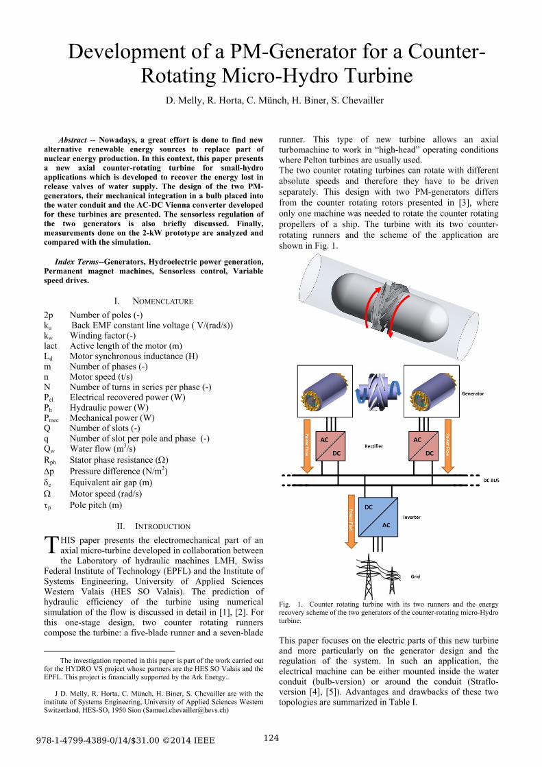
The Vienna rectifier realized at the HES-SO is presented in Fig.13. Before testing the rectifier on the generator, some measurements presented in this paper have been done on the grid. The grid voltage is assumed to represents the induced voltage of the machine while an inductance, is placed between the Vienna rectifier and the grid as presented in Fig. 14. This set up models the PM-Generator.
Fig. 13. Vienna rectifier realized at the HES-SO. The inductances and resistors used here, have the same values as the winding inductances and resistors of the machines. The DC bus is generated and controlled with a four quadrant power supply. Its voltage (uBUS) is set to 750V.
Fig. 14. Vienna Rectifier preliminary tests connections on grid. Fig. 15 shows the phase voltage uRN, the corresponding current (iR) and the commuted voltage measured between the R phase input of the rectifier and the DC bus middle point. In order to have a minimum current ripple the switching frequency is fixed to 20 kHz. The first results show that the implemented blocks in Fig. 8 work perfectly on the grid. Preliminary tests show an efficiency higher than 96% for the nominal current of the machine. The Vienna has to be tested on the machine to check the speed regulation.
C. System measurements
The whole system mounted on the test bench is presented in Fig. 16. First results show a higher thermal dissipation of the motor losses as expected, since the motor temperature increases by only 40°C for the nominal working point. The water flow for this measurement was fixed to Q = 43 m3/h. This lead to a coefficient of heat transfer h = 170 (W/m2K) under assumption that all the losses are transferred to the water only via the surface of the stator package.
128
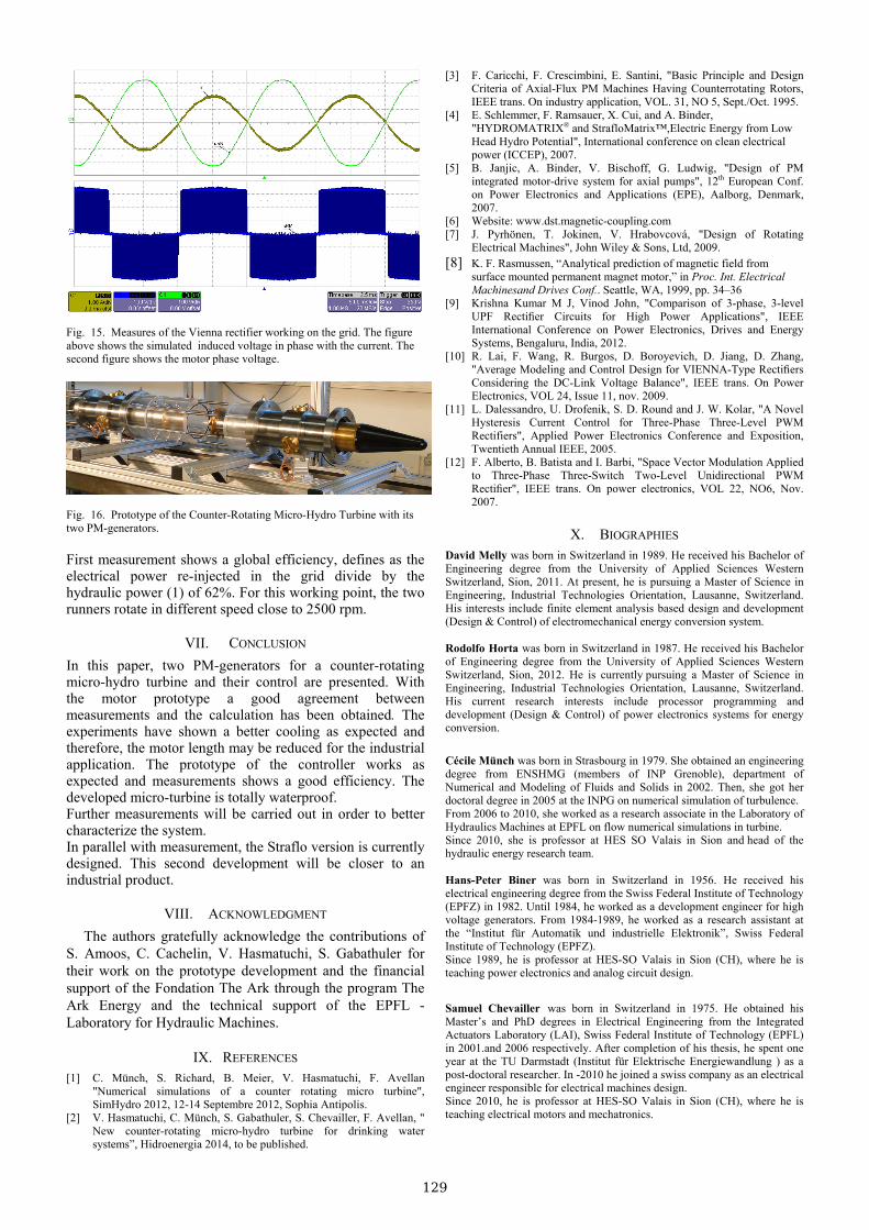
Fig. 15. Measures of the Vienna rectifier working on the grid. The figure above shows the simulated induced voltage in phase with the current. The second figure shows the motor phase voltage.
Fig. 16. Prototype of the Counter-Rotating Micro-Hydro Turbine with its two PM-generators. First measurement shows a global efficiency, defines as the electrical power re-injected in the grid divide by the hydraulic power (1) of 62%. For this working point, the two runners rotate in different speed close to 2500 rpm.
VII. CONCLUSION
In this paper, two PM-generators for a counter-rotating micro-hydro turbine and their control are presented. With the motor prototype a good agreement between measurements and the calculation has been obtained. The experiments have shown a better cooling as expected and therefore, the motor length may be reduced for the industrial application. The prototype of the controller works as expected and measurements shows a good efficiency. The developed micro-turbine is totally waterproof. Further measurements will be carried out in order to better characterize the system. In parallel with measurement, the Straflo version is currently designed. This second development will be closer to an industrial product.
VIII. ACKNOWLEDGMENT
The authors gratefully acknowledge the contributions of S. Amoos, C. Cachelin, V. Hasmatuchi, S. Gabathuler for their work on the prototype development and the financial support of the Fondation The Ark through the program The Ark Energy and the technical support of the EPFL - Laboratory for Hydraulic Machines.
IX. REFERENCES [1] C. Münch, S. Richard, B. Meier, V. Hasmatuchi, F. Avellan
"Numerical simulations of a counter rotating micro turbine", SimHydro 2012, 12-14 Septembre 2012, Sophia Antipolis.
[2] V. Hasmatuchi, C. Münch, S. Gabathuler, S. Chevailler, F. Avellan, " New counter-rotating micro-hydro turbine for drinking water systems”, Hidroenergia 2014, to be published.
[3] F. Caricchi, F. Crescimbini, E. Santini, "Basic Principle and Design Criteria of Axial-Flux PM Machines Having Counterrotating Rotors, IEEE trans. On industry application, VOL. 31, NO 5, Sept./Oct. 1995.
[4] E. Schlemmer, F. Ramsauer, X. Cui, and A. Binder, "HYDROMATRIX® and StrafloMatrix™,Electric Energy from Low Head Hydro Potential", International conference on clean electrical power (ICCEP), 2007.
[5] B. Janjic, A. Binder, V. Bischoff, G. Ludwig, "Design of PM integrated motor-drive system for axial pumps", 12th European Conf. on Power Electronics and Applications (EPE), Aalborg, Denmark, 2007.
[6] Website: www.dst.magnetic-coupling.com [7] J. Pyrhönen, T. Jokinen, V. Hrabovcová, "Design of Rotating
Electrical Machines", John Wiley & Sons, Ltd, 2009. [8] K. F. Rasmussen, “Analytical prediction of magnetic field from
surface mounted permanent magnet motor,” in Proc. Int. Electrical Machinesand Drives Conf.. Seattle, WA, 1999, pp. 34–36
[9] Krishna Kumar M J, Vinod John, "Comparison of 3-phase, 3-level UPF Rectifier Circuits for High Power Applications", IEEE International Conference on Power Electronics, Drives and Energy Systems, Bengaluru, India, 2012.
[10] R. Lai, F. Wang, R. Burgos, D. Boroyevich, D. Jiang, D. Zhang, "Average Modeling and Control Design for VIENNA-Type Rectifiers Considering the DC-Link Voltage Balance", IEEE trans. On Power Electronics, VOL 24, Issue 11, nov. 2009.
[11] L. Dalessandro, U. Drofenik, S. D. Round and J. W. Kolar, "A Novel Hysteresis Current Control for Three-Phase Three-Level PWM Rectifiers", Applied Power Electronics Conference and Exposition, Twentieth Annual IEEE, 2005.
[12] F. Alberto, B. Batista and I. Barbi, "Space Vector Modulation Applied to Three-Phase Three-Switch Two-Level Unidirectional PWM Rectifier", IEEE trans. On power electronics, VOL 22, NO6, Nov. 2007.
X. BIOGRAPHIES David Melly was born in Switzerland in 1989. He received his Bachelor of Engineering degree from the University of Applied Sciences Western Switzerland, Sion, 2011. At present, he is pursuing a Master of Science in Engineering, Industrial Technologies Orientation, Lausanne, Switzerland. His interests include finite element analysis based design and development (Design & Control) of electromechanical energy conversion system. Rodolfo Horta was born in Switzerland in 1987. He received his Bachelor of Engineering degree from the University of Applied Sciences Western Switzerland, Sion, 2012. He is currently pursuing a Master of Science in Engineering, Industrial Technologies Orientation, Lausanne, Switzerland. His current research interests include processor programming and development (Design & Control) of power electronics systems for energy conversion.
Cécile Münch was born in Strasbourg in 1979. She obtained an engineering degree from ENSHMG (members of INP Grenoble), department of Numerical and Modeling of Fluids and Solids in 2002. Then, she got her doctoral degree in 2005 at the INPG on numerical simulation of turbulence. From 2006 to 2010, she worked as a research associate in the Laboratory of Hydraulics Machines at EPFL on flow numerical simulations in turbine. Since 2010, she is professor at HES SO Valais in Sion and head of the hydraulic energy research team. Hans-Peter Biner was born in Switzerland in 1956. He received his electrical engineering degree from the Swiss Federal Institute of Technology (EPFZ) in 1982. Until 1984, he worked as a development engineer for high voltage generators. From 1984-1989, he worked as a research assistant at the “Institut für Automatik und industrielle Elektronik”, Swiss Federal Institute of Technology (EPFZ). Since 1989, he is professor at HES-SO Valais in Sion (CH), where he is teaching power electronics and analog circuit design.
Samuel Chevailler was born in Switzerland in 1975. He obtained his Master’s and PhD degrees in Electrical Engineering from the Integrated Actuators Laboratory (LAI), Swiss Federal Institute of Technology (EPFL) in 2001.and 2006 respectively. After completion of his thesis, he spent one year at the TU Darmstadt (Institut für Elektrische Energiewandlung ) as a post-doctoral researcher. In -2010 he joined a swiss company as an electrical engineer responsible for electrical machines design. Since 2010, he is professor at HES-SO Valais in Sion (CH), where he is teaching electrical motors and mechatronics.
129
Powered by TCPDF (www.tcpdf.org)