Development of a Centrifugal Pump Adapter to Stabilized ... · (CFD). This device induces ... A...
6
CHEMICAL ENGINEERING TRANSACTIONS VOL. 57, 2017 A publication of The Italian Association of Chemical Engineering Online at www.aidic.it/cet Guest Editors: Sauro Pierucci, Jiří Jaromír Klemeš, Laura Piazza, Serafim Bakalis Copyright © 2017, AIDIC Servizi S.r.l. ISBN 978-88-95608- 48-8; ISSN 2283-9216 Development of a Centrifugal Pump Adapter to Stabilized Production of Microbubbles Nathália M. P. Rocha e Silva* a,d , Fernanda C. P. Rocha e Silva b,d , Juliana M. Luna c,d , Mohand Benachour a,d , Leonie A. Sarubbo c,d , Valdemir A. Santos c,d a Department of Chemical Engineering, Federal University of Pernambuco - Brazil b Northeast Biotechnology Network, Federal Rural University of Pernambuco - Brazil c Centre of Sciences and Technology, Catholic University of Pernambuco - Brazil d Advanced Institute of Technology and Innovation (IATI) - Brazil [email protected] In this paper we developed a centrifugal pump adapter to produce microbubbles, after understanding the process of generating those microbubbles with the aid of simulations via Computational Fluid Dynamics (CFD). This device induces a flow of air in the suction line centrifugal pump, due to the negative pressure existing at this point in the installation. The adapter has been tested with the help of experiments type Central Composite Rotatable Design (CCRD). The independent variables were the ratio between the air flow and water (X1) and the ratio between the water flow and oil (X2). The experimental tests were applied to a pilot prototype DAF. The results indicated that the process of DAF can be highly effective using a device which enables the controlled air entry into a centrifugal pump, enabling the stable operation conditions to reduce experimental error. The desired stability was obtained, having registered an increase of 80.0% to 98.1% separation efficiency of the oily effluent, when we compared the microbubble production conditions, without and with using the adapter. Thus, the system proved to be advantageous compared to conventional water saturation process, allowing the reduction of space, equipment costs, labor, work and energy. 1. Introduction There are some methods of treatment of industrial waters that can vary according some factors, such as, volumes, constitution of the water, limits of the current environmental legislation, among others. The treatment of oily waters, in particular, has the purpose of reducing the concentration of oil dispersion in the water so they are then discarded in the bodies of water or reused in the process (Rocha e Silva et al., 2015). The shear caused by pumps, valves, hydraulic constrictions and other equipment, disperses the oil and the water forming emulsions, which can be highly stabilized by the presence of natural surfactant substances of petroleum and other reagents added during the process of production of lubricating oils and fuels, which makes it difficult to treat them (Sarubbo et al., 2012; Busto et al., 2016). Conventional oily water treatment is basically done by water-oil separators (SAO), which use the gravitational force principle for oil/water separation. The treated water reaches levels of oil removal in the range of 200 mg/L, due mainly to the presence of emulsified oil, which is difficult to remove by flotation, requiring more efficient processes, because its improper disposal can cause impacts in human health (Rodriguez-Mateus et al., 2016). The flotation technology by dissolved air (DAF) is presented as a very effective alternative. However, one of the parameters responsible for the efficiency of this technique of solid-liquid and liquid-liquid separation is the size and number of microbubbles present in the medium to form flakes. In the case of water-oil separation, the dispersed oil phase droplets are surrounded by microbubbles of air and the final structure (flakes) floate. In conventional DAF equipment, it uses a tank for compressed air with the effluent of the saturation produced by a compressor. The result is a production of microbubbles. However, this technique has disadvantages such as heterogeneity of the microbubbles, the microbubbles size of instability with the passage of usage time, the physical space needed for the saturation tank and energy expenditure for the production of compressed air. A DOI: 10.3303/CET1757201 Please cite this article as: Rocha E Silva N.M.P., Rocha E Silva F., Luna J.M., Benachour M., Sarubbo L.A., Santos V.A., 2017, Development of a centrifugal pump adapter to stabilized production of microbubbles, Chemical Engineering Transactions, 57, 1201-1206 DOI: 10.3303/CET1757201 1201
-
Upload
phungkhanh -
Category
Documents
-
view
216 -
download
0
Transcript of Development of a Centrifugal Pump Adapter to Stabilized ... · (CFD). This device induces ... A...

CHEMICAL ENGINEERING TRANSACTIONS
VOL. 57, 2017
A publication of
The Italian Association
of Chemical Engineering Online at www.aidic.it/cet
Guest Editors: Sauro Pierucci, Jiří Jaromír Klemeš, Laura Piazza, Serafim Bakalis Copyright © 2017, AIDIC Servizi S.r.l.
ISBN 978-88-95608- 48-8; ISSN 2283-9216
Development of a Centrifugal Pump Adapter to Stabilized Production of Microbubbles
Nathália M. P. Rocha e Silva*a,d, Fernanda C. P. Rocha e Silvab,d, Juliana M. Lunac,d, Mohand Benachoura,d, Leonie A. Sarubboc,d, Valdemir A. Santosc,d
aDepartment of Chemical Engineering, Federal University of Pernambuco - Brazil bNortheast Biotechnology Network, Federal Rural University of Pernambuco - Brazil cCentre of Sciences and Technology, Catholic University of Pernambuco - Brazil dAdvanced Institute of Technology and Innovation (IATI) - Brazil [email protected]
In this paper we developed a centrifugal pump adapter to produce microbubbles, after understanding the process of generating those microbubbles with the aid of simulations via Computational Fluid Dynamics (CFD). This device induces a flow of air in the suction line centrifugal pump, due to the negative pressure existing at this point in the installation. The adapter has been tested with the help of experiments type Central
Composite Rotatable Design (CCRD). The independent variables were the ratio between the air flow and water (X1) and the ratio between the water flow and oil (X2). The experimental tests were applied to a pilot prototype DAF. The results indicated that the process of DAF can be highly effective using a device which enables the controlled air entry into a centrifugal pump, enabling the stable operation conditions to reduce experimental error. The desired stability was obtained, having registered an increase of 80.0% to 98.1% separation efficiency of the oily effluent, when we compared the microbubble production conditions, without and with using the adapter. Thus, the system proved to be advantageous compared to conventional water saturation process, allowing the reduction of space, equipment costs, labor, work and energy.
1. Introduction
There are some methods of treatment of industrial waters that can vary according some factors, such as, volumes, constitution of the water, limits of the current environmental legislation, among others. The treatment of oily waters, in particular, has the purpose of reducing the concentration of oil dispersion in the water so they are then discarded in the bodies of water or reused in the process (Rocha e Silva et al., 2015). The shear caused by pumps, valves, hydraulic constrictions and other equipment, disperses the oil and the water forming emulsions, which can be highly stabilized by the presence of natural surfactant substances of petroleum and other reagents added during the process of production of lubricating oils and fuels, which makes it difficult to treat them (Sarubbo et al., 2012; Busto et al., 2016). Conventional oily water treatment is basically done by water-oil separators (SAO), which use the gravitational force principle for oil/water separation. The treated water reaches levels of oil removal in the range of 200 mg/L, due mainly to the presence of emulsified oil, which is difficult to remove by flotation, requiring more efficient processes, because its improper disposal can cause impacts in human health (Rodriguez-Mateus et al., 2016). The flotation technology by dissolved air (DAF) is presented as a very effective alternative. However, one of the parameters responsible for the efficiency of this technique of solid-liquid and liquid-liquid separation is the size and number of microbubbles present in the medium to form flakes. In the case of water-oil separation, the dispersed oil phase droplets are surrounded by microbubbles of air and the final structure (flakes) floate. In conventional DAF equipment, it uses a tank for compressed air with the effluent of the saturation produced by a compressor. The result is a production of microbubbles. However, this technique has disadvantages such as heterogeneity of the microbubbles, the microbubbles size of instability with the passage of usage time, the physical space needed for the saturation tank and energy expenditure for the production of compressed air. A
DOI: 10.3303/CET1757201
Please cite this article as: Rocha E Silva N.M.P., Rocha E Silva F., Luna J.M., Benachour M., Sarubbo L.A., Santos V.A., 2017, Development of a centrifugal pump adapter to stabilized production of microbubbles, Chemical Engineering Transactions, 57, 1201-1206 DOI: 10.3303/CET1757201
1201
new technique for the production of microbubbles has been the use of multiphase pumps, but this equipment as well as its operating complexity is costly and requires high power for the manufacturer to meet requests for supply. The present work aimed to perform experiments to identify stable operating conditions of centrifugal pumps in the production of microbubbles. Statistical planning techniques were utilized through Rotational Central Compound Design (RCCD) with the intention of evaluating an influence of water/oil ratios to produce microbubbles. In order to promote a stabilization of the centrifugal pump inlet, a pressure control device was proposed in the suction line where the efficiency of separation was determined for the system without and with this adapter.
2. Materials and Methods
2.1 Pilot scale dissolved air flotation (DAF) system
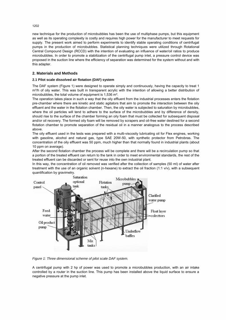
The DAF system (Figure 1) were designed to operate simply and continuously, having the capacity to treat 1 m³/h of oily water. This was built in transparent acrylic with the intention of allowing a better distribution of microbubbles, the total volume of equipment is 1,536 m³. The operation takes place in such a way that the oily effluent from the industrial processes enters the flotation pre-chamber where there are kinetic and static agitators that aim to promote the interaction between the oily effluent and the water in the flotation chamber. Then, the oily water is subjected to saturation by microbubbles, where the oil particles will tend to adhere to the surface of the microbubbles and by difference of density, should rise to the surface of the chamber forming an oily foam that must be collected for subsequent disposal and/or oil recovery. The formed oily foam will be removed by scrapers and oil-free water destined for a second flotation chamber to promote separation of the residual oil in a manner analogous to the process described above. The oily effluent used in the tests was prepared with a multi-viscosity lubricating oil for Flex engines, working with gasoline, alcohol and natural gas, type SAE 20W-50, with synthetic protector from Petrobras. The concentration of the oily effluent was 50 ppm, much higher than that normally found in industrial plants (about 10 ppm on average). After the second flotation chamber the process will be complete and there will be a recirculation pump so that a portion of the treated effluent can return to the tank in order to meet environmental standards, the rest of the treated effluent can be discarded or sent for reuse into the own industrial plant. In this way, the concentration of oil removed was verified after the collection of samples (50 ml) of water after treatment with the use of an organic solvent (n-hexane) to extract the oil fraction (1:1 v/v), with a subsequent quantification by gravimetry.
Figure 1: Three dimensional scheme of pilot scale DAF system.
A centrifugal pump with 2 hp of power was used to promote a microbubbles production, with an air intake controlled by a router in the suction line. This pump has been installed above the liquid surface to ensure a negative pressure at the pump inlet.
1202

It is important to note that it is necessary to prevent excessive entering of air in the the pump, otherwise its efficiency may be reduced due to the accumulation of air inside it. If this occurs, the pump enters the cavitation process and stops the transportation of water. 2.2 Geometry of the centrifugal pump adapter
Figure 2 shows the composition of a set of parts, which was called an adapter. In this assembly, no centrifugal pump suction is introduced, via: a check valve (3), a needle valve (5) and a rotameter (9). The equipment was designed to provide stability to obtain a constant flow of microbubbles during the pump operation. A check valve requires a constant negative pressure, above a set value, for an aspiration necessary to generate the microbubbles. The needle-type valve installed between the rotor and check valve keeps the airflow and float stabilized, which is necessary to establish stable operating conditions.The mentioned components are connected by nipples (2, 4, 6 and 8) and knee (5). The entire assembly is connected to the pump inlet by a union (1).
Figure 2: Detailed diagram of the adapter.
Figures 3 and 4 show the microbubble adapter installed in the suction line of the centrifugal pump used in the microbubble generation of the FAD pilot prototype.
Figure 3: The microbubble production system consisting of the centrifugal pump, rotor and adapter.
1203

Figure 4: Adapter installed at the inlet of the centrifugal pump.
In summary, the device is operated based on the pressure difference within the suction/feed line of the centrifugal pump due to the presence of atmospheric air. The check valve is intended to control the flow of air adhering to the pump, when there is atmospheric air inside the pipeline, there is an increase in the internal pressure, forcing the valve to reduce the air flow so there is a stabilization of the system under cavitation.
2.3 Data analysis
Initially a RCCD 22 was applied to define the operating conditions of the pilot prototype. The independent variables were coded at five levels (-1.41, -1, 0, +1, +1.41). The coded levels of the independent variables used in the response surface methodology (RSM) design are listed in Tables 1 and 2.
Table 1: Experimental range and levels of independent variables for separation efficiency in the pilot scale
DAF system without the adapter.
Test variables
Range and levels -1.41 -1.00 0.00 +1.00 +1.41
Ratio between the air and water flow rates .103, (X1)
0.30
0.50
1.00
1.5
1.71
Ratio between the water and feed oil flow rates .104, (X2)
0.56
0.70
1.05
1.40
1.54
Table 2: Experimental range and levels of independent variables for separation efficiency in the pilot scale
DAF system with the adapter.
Test variables
Range and levels -1.41 -1.00 0.00 +1.00 +1.41
Ratio between the air and water flow rates .103, (X’1)
0.30
0.50
1.00
1.5
1.71
Ratio between the water and feed oil flow rates .104, (X’2)
0.56
0.70
1.05
1.40
1.54
In both RCCD, the factors involving relations between flow rates aimed the use of non-dimension variables, which may facilitate a future correlation with scale-up. The response variable was the separation efficiency of the pilot prototype calculated according to Eq. (1):
𝑌 =𝐶𝐼−𝐶0
𝐶𝐼. 100 % (1)
1204

Where Y is the percent separation efficiency, while CI and CO are the oil concentrations in the inlet and outlet flow in ppm, respectively. ANOVA, the determination of regression coefficients and the construction of graphs were performed using the Statistica® software, version 8.0 (Statsoft Inc, USA).
3. Results and discussion
The data of the responses variable collected according to the RCCD applied to the pilot scale DAF system, with and without the adapter are shown in Table 3. Tables and graphics were obtained to provide a mathematical model to predict the response variable separation efficiency in the pilot prototype as a function of the independent variables adopted.
Tabela 3: Central composite (non-factorial) surface design matrix and experimental values of observed factors
on separation efficiency in the pilot scale DAF system with (Y’) and without (Y) use of the adapter to produce
microbubbles.
Run number Ratio between the air and water flow rates
(X1/X’1).10³
Ratio between the water and feed oil flow rates (X2/X’2).104
Y (%) Y’ (%)
1 0.50(-1) 0.7(-1) 23.40 42.00 2 0.50(-1) 1.4(+1) 71.00 88.30 3 1.50(+1) 0.7(-1) 26.90 44.70 4 1.50(+1) 1.4(+1) 58.50 81.10 5 0.30(-1.41) 1.05(0.0) 44.30 61.50 6 1.71(+1.41) 1.05(0.0) 25.70 45.00 7 1.00(0.0) 0.56(-1.41) 15.00 37.00 8 1.00(0.0) 1.54(+1.41) 62.00 82.60 9 1.00(0.0) 1.05(0.0) 80.00 96.30 10 1.00(0.0) 1.05(0.0) 72.00 98.10 11 1.00(0.0) 1.05(0.0) 65.00 97.90 12 1.00(0.0) 1.05(0.0) 74.00 97.00
The graphical representation provides a method to visualize the relation between the response and experimental levels of each variable, and the type of interactions between test variables in order to deduce the optimum conditions. Figure 5 depicts the three-dimensional plot showing the quadratic effect of X1 and X2 factors. It is observed that the ranges of values were adequately chosen allowing the generation of maximum points (oil separation efficiency of 80% without use and 98% using the adapter).
Figure 5: Three-dimensional surface plot of the combined effect of observed factors on separation efficiency in
the pilot scale DAF system without use (A) and with use of the adapter (B).
1205

It was observed an improvement of about 18.0% in the effluent separation efficiency through the FAD system, where the best results were obtained when the air/water (X1) and water/oil (X2) conditions were found at the central point, meaning that as conditions for the process are X1=1.0 and X2=1.05. Our results are in agreement with the ones described in the literature (Menezes et al., 2011; Watcharasing et al., 2012) though, it is important to note that the works in question have used biosurfactants as collectors in the flotation process aiming to increase efficiency. However, the present work obtained significant results only by adjusting physical and operational parameters of the DAF system.
4. Conclusion
The use of a centrifugal pump for the production of microbubbles using atmospheric air proved to be a very efficient alternative. The results indicated that the FAD process can be very effective with the use of an adapter that allows a control input in the centrifugal pump, allowing the same operation under stabilized operating conditions. The use of the adapter in the suction line of the centrifugal pump caused a significant increase in oil removal in a synthetic effluent from 80.0% to 98.1%. The method of microbubble production proposed in this work constitutes a significant advance in dissolved air flotation technology, mainly for testing, in large part, in small and medium-sized facilities.
Acknowledgments
This study was funded by the Foundation for the Support of Science and Technology of the State of Pernambuco (FACEPE), the Research and Development Program from National Agency of Electrical Energy (ANEEL) and Thermoelectric Candeias Energia (Global Group), the National Council for Scientific and Technological Development (CNPq), and the Coordination for the Improvement of Higher Level Education Personnel (CAPES). The authors are grateful to the laboratories of the Centre for Sciences and Technology of the Universidade Católica de Pernambuco, Brazil.
Reference
Busto Y., Palacios E.W., Ríos L.M., Martín J., Jiménez Y., Pérez H., Yera M., 2016, Economic Feasibility Study on the Wastewater Treatment Plant in Fuel Companies. A Cuban Study Case, Chemical Engineering Transactions, 52, 877-882, DOI: 10.3303/CET1652147.
Menezes, C.T.B.; Banos, E.C.; Rufino, R.D.; Luna, J.M.; Sarubbo, L.A., 2011, Replacing synthetic with microbial surfactants as collectors in the treatment of aqueous effluent produced by acid mme drainage, using the dissolved air flotation technique. Applied Biochemistry and Biotechnology, 163, 540-546, DOI: 10.1007/s12010-010-9060-7.
Rocha e Silva, F. C. P., Rocha e Silva, N. M. P., Moura, A.E., Galdino, R.A.; Luna, J.M.; Rufino, R.D.; Santos, V.A.; Sarubbo, L.A., 2015, Effect of biosurfactant addition in a pilot scale dissolved air flotation system, Separation Science and Technology, 50, 618-625, DOI: 10.1080/01496395.2014.957319.
Rodriguez-Mateus Z., Agualimpia B., Zafra G., 2016, Isolation and Molecular Characterization of Microorganisms with Potential for the Degradation of Oil and Grease from Palm Oil Refinery Wastes, Chemical Engineering Transactions, 49, 517-522, DOI: 10.3303/CET1649087.
Sarubbo, L.A., Luna, J.M., Rufino, R.D., Farias, C.B.B., Santos, V.A., 2012, Production of biosurfactants for application in the removal of hydrophobic contaminants originated by the petroleum industry, Chemical Engineering Transactions, 27, 7-12, DOI: 10.3303/CET1227002.
Watcharasing, S.; Kongkowit, W.; Scamehorn, S., 2009, Motor oil removal from water by continuous froth flotation using extended surfactant: Effects of air bubble parameters and surfactant concentration, Separation and Purification Technology, 70, 179-189, DOI: 10.1016/j.seppur.2009.09.014.
1206