Centrifugal Pump 2
47
-
Upload
franklin-jose-almera-acosta -
Category
Documents
-
view
184 -
download
3
Transcript of Centrifugal Pump 2


2
TABLE OF CONTENTS Introduction ---------------------------------------------------------------------------- 5
General Instructions ------------------------------------------------------------------ 5
Section A: INSTALLATION-------------------------------------------------------- 5
Compatibility ------------------------------------------------------------------------------------5 Location ------------------------------------------------------------------------------------------5 Foundation ---------------------------------------------------------------------------------------5 Alignment ----------------------------------------------------------------------------------------6 Piping---------------------------------------------------------------------------------------------7
SECTION B: PREPARATION FOR OPERATION ----------------------------- 8
Preliminary Lubrication ------------------------------------------------------------------------8 Mechanical Seal Pumps ------------------------------------------------------------------------8 Packed Pumps -----------------------------------------------------------------------------------8 Pump Rotation-----------------------------------------------------------------------------------8 Pump Priming -----------------------------------------------------------------------------------8
SECTION C: OPERATION --------------------------------------------------------- 9
Operating Condition Envelope ----------------------------------------------------------------9 Documentation ----------------------------------------------------------------------------------9
Lubrication--------------------------------------------------------------------------------9 Grease Lubrication for Bearings ----------------------------------------------------- 10 Grease Lubrication for Packing ------------------------------------------------------ 10 Water Lubrication for Packing ------------------------------------------------------- 10
SECTION D: MAINTENANCE--------------------------------------------------- 10
Disassembly ----------------------------------------------------------------------------------- 10 Inspection -------------------------------------------------------------------------------------- 11 Assembly--------------------------------------------------------------------------------------- 12
Shaft and Bearing Sub-Assembly---------------------------------------------------- 12 Power Frame Sub-Assembly --------------------------------------------------------- 13 Stuffing Box and Components ------------------------------------------------------- 14 Fluid End Assembly ------------------------------------------------------------------- 15
General Operating and Storage Instructions----------------------------------------------- 15

3
TABLE OF FIGURES
Figure 1: Offset Alignment with a Dial Indicator .......................................... 6
Figure 2: Angular Alignment with a Dial Indicator ....................................... 6
Figure 3: Offset Alignment with a Straight edge ........................................... 7
Figure 4: Angular Alignment with a Straight edge ........................................ 7
Figure 5: Inboard bearing cover with grease fitting ..................................... 10
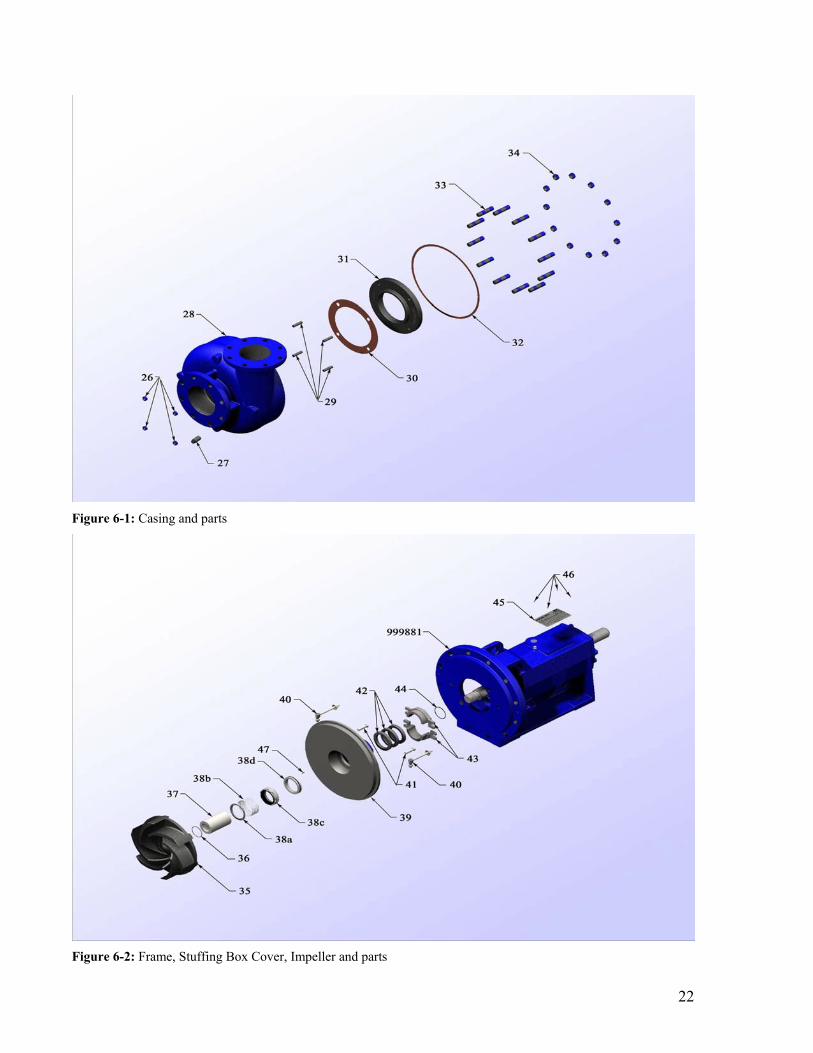
Figure 6-1 Casing and parts .......................................................................... 22
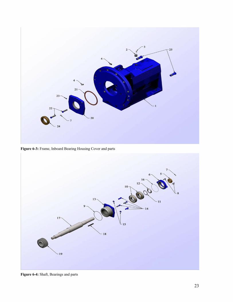
Figure 6-2: Frame, Stuffing Box Cover, Impeller and parts ........................ 22
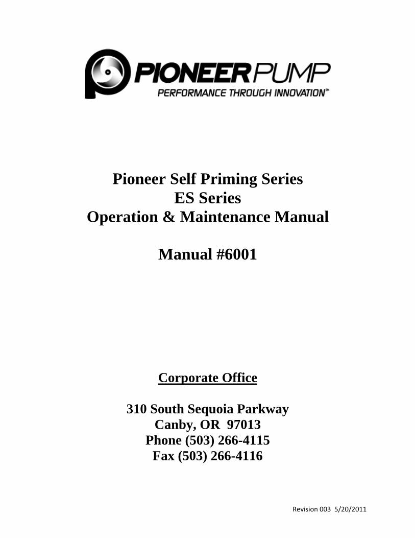
Figure 6-3: Frame, Inboard Bearing Housing Cover and parts .................... 23
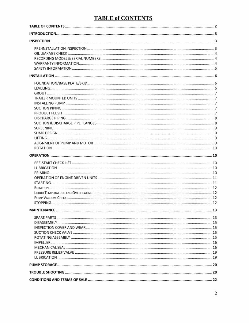
Figure 6-4: Shaft, Bearings and parts ........................................................... 23

4
TABLE OF TABLES
Table 1: Mud Hog Spare Parts List. ............................................................ 18
Table 2: Mud Hog Repair Kits .................................................................... 21

5
Introduction
This manual contains instructions for the installation, operation and maintenance of Baker SPD’s Mud Hog 2.5 Centrifugal Pump. After going through this manual, if you feel that some of your questions or situations that you are dealing with, have not been addressed, please contact your local Baker SPD Distributor or Salesman for further assistance. Baker SPD’s Mud Hog 2.5 is a pump designed to replace some older and existing 2.5” pumps, with a similar but superior product. We have designed this pump keeping in mind a longer life, reliability and easier maintenance. Some of its outstanding features that contribute towards its popularity and success are;
1. Pump casing with a replaceable wear
pad 2. Stainless steel shaft sleeves 3. Stainless steel casing nuts 4. Grease lubricated bearings 5. Leakage and contamination
prevention through labyrinth seals
It is very important to closely follow proper installation, operation and maintenance guidelines in order to ensure a smooth and efficient pumping operation and a longer equipment life.
General Instructions 1. The motor/driver must operate the
pump in a manner that the rotation of the pump impeller when viewed from the suction (front) side of the pump is COUNTER-CLOCKWISE. The pump must not be operated in
the reverse direction if damage to the pump is to be avoided.
2. The suction and discharge valves must not be completely closed when operating the pump.
3. The packing should be adjusted in a manner that a small amount of leakage remains for lubrication and cooling purposes.
4. For drilling mud operations, care must be taken to prevent seepage from the packing to dry out and coagulate in the areas of the front seal and the slinger.
5. Do not operate the pump outside its designed performance envelope.
Section A: INSTALLATION Compatibility
The Mud Hog 2.5 has been designed to ensure that it can replace existing pumps of the same nominal size. To this end, its outside dimensions are guaranteed to match up to the existing bases, piping, couplings etc.
Location To eliminate the need for priming,
the pump suction should be at a lower level than the level of the liquid in the supply tank/reservoir.
Foundation It is recommended to pour a concrete
foundation on a solid base and it should be big enough to support the whole pump unit. The rigidity of the base plate will play an important role in damping out structural vibrations so the foundation must be thick enough to accomplish that. Refer to Hydraulic Institute’s Standard ANSI/HI 1.4-2000 for guidelines on this subject. Care must be taken to level the base plate in a horizontal position. Also, when the

6
application dictates the use of fabricated bases, the foundation design must account for it properly, so that it can effectively dampen the resulting resonant vibrations.
Alignment For any rotating machinery, the
alignment of power transmitting and power consuming parts is critical for its safe and long lasting service. Even if the motor and the pump were aligned before shipping, it is very important to check the alignment after installation to ensure that the arrangement has not moved during transportation or handling. We cannot overemphasize proper alignment since it can mean the difference between a smooth and long lasting pump operation as opposed to high vibrations and even failure of bearings, coupling, pump or the motor. It should be noted that one must not try to align the pump and the motor until its flange and mounting bolts have been tightened.
To perform the coupling alignment
with dial indicators, which are the instruments of choice for such procedures, the dial indicator is attached to one coupling half with the indicator dial button resting on the outside diameter (OD) of the other coupling half. This will give the offset misalignment between the two shafts. In order to find out the angular misalignment, let the dial indicator button ride on the face of the other coupling half, instead of its OD. A TIR of 0.005” or less is usually considered acceptable by most manufacturers. If the TIR is more than that, it can be adjusted by loosening the pump or driver mounting bolts, adding or removing shims accordingly and then
tightening down the bolts again. See Figures 1 & 2 below.
Figure 1: Offset Alignment with a Dial Indicator
Figure 2: Angular Alignment with a Dial Indicator
For situations where a dial indicator is not available, one can use a straight edge to perform a reasonable alignment. This method works better when the coupling has a rubber or a flexible drive element.
To check for offset misalignment,
place the straight edge on the OD of the couplings. If they are aligned there will not be any gaps under the straight edge. A max gap of 1/64” is allowed. This procedure should be repeated for at least one more location on the circumference of the coupling 90 degrees from the first position.
To check for angular misalignment,
the two coupling mating faces should not have a variation in the gap, all around the faces. A maximum variation of 1/64” is permissible.

7
See figures 3 & 4 below.
Figure 3: Offset Alignment with a Straight edge
Figure 4: Angular Alignment with a Straight edge
More information on coupling alignment can be found in the Hydraulic Institute’s Standard ANSI/HI 1.4-2000.
Piping It is important that the piping should
line up to the pump without it having to be drawn closer by tightening the companion flange bolts. Also, the pump should not have to support the weight of the piping. For this to happen, it is better to have the piping anchored independently but as close to the pump as possible. It should also be pointed out that the piping should not be connected to the pump until the grout has hardened and after the motor and pump mounting bolts have been tightened. Suction Piping
Suction piping can not only play a critical role in causing vibration and cavitation in centrifugal pumps, but can also be responsible for causing packing
and mechanical seal failures as well as putting extreme loads on the bearings. It is therefore very important that the size of the suction piping be at least the same or larger than the suction port of the pump.
To eliminate air pockets in the suction line, it is beneficial for the suction line have a gradual slope down to the supply tank or source.
It is recommended that the flow through the pump should not be controlled by adjusting a valve in the suction line. However, this does not preclude the use of a suction line shut off valve to be used when the pump has to be inspected or removed for maintenance purposes.
In order to have a relatively turbulence free flow into the pump, it is good practice to have a straight length of pipe, at least twice its diameter in length e.g. a 6 inch suction pipe should have at least one foot of straight pipe just before the pump.
In situations which might require a flexible hose to be used in the suction line, it is imperative that such a flexible hose be of the non-collapsing type, since it is not uncommon to have suction pressures which are below atmospheric pressure. In such a scenario, there is a real possibility of starving the pump and thus causing it to overheat. Discharge Piping
Like the suction piping, a shut off valve should be used in the discharge piping as well, to enable the removal of the pump for maintenance purposes. A throttle valve can be used in the discharge line to operate the pump at it is design point, if the exact operating conditions are not known.
In case of a closed pressurized loop, it is necessary to have a check valve

8
between the pump and the throttle valve, to prevent the product from flowing back through the pump. In the absence of the check valve, such a circumstance can cause the impeller to come loose and cause damage to the pump and also result in leakage beneath the shaft sleeve.
SECTION B: PREPARATION FOR OPERATION
Before starting the pump, it is good practice to always go through the following simple checks; 1. Check for impeller’s free rotation by
turning the shaft by hand 2. Make sure that the suction line and
the pump are full of fluid and that the suction valve is fully open.
3. Slightly open the discharge valve and then open it fully once the pump is running.
Preliminary Lubrication Our standard pumps come pre
lubricated with grease (oil lubrication is available as an option). The operators / customers do not have to worry about lubricating the pump for the first year of operation. At that time, the pump can be lubricated through the outboard and inboard bearing covers by removing the plugs and replacing them with the appropriate lubrication fittings.
Usually, labyrinth seals are provided at both bearing ends, and they serve to keep the temperature from rising, by also acting as vents. But in cases where the labyrinth seals are not provided, it is recommended to keep the air vent clean.
Mechanical Seal Pumps It is vital that these pumps are never
started dry otherwise it will cause irreparable damage to the seal faces. The
factory installs and adjusts the mechanical seals before shipping the pumps. The seal models currently being provided with the Mud Hog 2.5 do not require external flush.
Pumps with mechanical seals come with 3 rings of backup packing which should be kept completely loose until a seal failure occurs. Only then should they be tightened down to prevent leakage.
Packed Pumps When starting packed pumps, the
packing should be loose and the packing gland nuts should only be hand tight. Once the pump starts running, slowly tighten the packing down. Make sure that there is some leakage through the packing, otherwise it will overheat and fail.
If outside flushing is required on either pump models, the flush lines should be connected and checked for flow through them, before starting the pump
Pump Rotation Before running the pump it is
important to find out the direction of rotation, since starting the Mud Hog 2.5 in the reverse direction can unscrew its impeller and thereby cause damage to the pump and the seal.
The direction of rotation can be checked in two ways. The motor can be uncoupled from the pump and then started to check its direction of rotation. Or a person can start and immediately shut off the coupled motor and pump assembly and have someone else watch as the shafting just turns over.
Pump Priming To prevent damage to the
mechanical seals or packing, there must
9
be liquid in the suction line and the casing, before the pump is started. Fill the suction line with the liquid and vent out any air that might be present in the line. The discharge valve should be barely open when the pump is started and only after the flow and pressure have stabilized that it should be adjusted to the required flow conditions. If the pressure fails to build, close the discharge valve and then reopen it to build discharge pressure. If flow difficulties continue, it may be an indication of improper installation or pump selection.
Operators must not run the pump with the suction valve closed under any circumstances, as it will immediately overheat the pump and cause major damage to various components.
Also, running the pump with the discharge valve closed should be allowed only for short durations as the energy being imparted to the pumped product by the impeller, will raise the temperature. If for some reason there is a need to keep the discharge valve closed for an extended length of time, then it is recommended to run a small (Ø0.25”or Ø0.50”) line, starting between the pump and the discharge valve and going back to the fluid supply tank.
SECTION C: OPERATION Operating Condition Envelope
This section only applies to pumps which do not have any external insulation and are exposed to the room temperature.
The maximum safe working pressure for cast iron is 175 psig at 150°F or 150 psig at 250°F. The conditions in between can be accordingly calculated. Whenever a high temperature (150°F plus) fluid is being pumped, cooling water should be
passed not only through the lantern ring but also over the exposed shaft, so as to dissipate the heat being generated at the labyrinth seal or lip seal and the bearings.
Documentation It is always helpful to maintain a
documentation history of the pump as it can improve our response time to help you. To this end, we provide a nameplate on each pump frame which contains some information which can help us identify the pump quickly. But in addition to that, it would be helpful to keep a record of the following information; 1. Motor horsepower 2. Operation frequency 3. Maintenance records and pertinent
information on any replacement parts.
Lubrication Your Mud Hog comes lubricated
with grease when it is shipped from the factory and it does not need to be lubricated more than once per year. The recommended grease is Lubri Plate 1200-2. When using different types of grease, care should be taken to use only those types of grease which are well suited to operate with each other.
Oil Lubrication for Bearings Oil lubrication for bearings is
available as an option but the pumps must be mounted in a horizontal position for oil lubricated pumps to work. This option is typically exercised when it is desired to lower the bearing temperature and hence reduce its wear.
It is recommended to use 10W30-non detergent motor oil. The oil can be filled through the hole provided on the top of the bearing frame. After removing the plug provided in the side of the frame, oil should be added from the top

10
until it starts to flow out from the side hole. This will indicate that the level of oil is correct. Adding more oil than recommended can actually be harmful to the pump.
Grease Lubrication for Bearings The outboard and inboard bearing
covers are provided with a grease fitting. It is recommended to add five shots of grease through the grease port at least once every six months, after the first year of service.
Figure 5: Outboard and Inboard bearing covers with grease fitting
Grease Lubrication for Packing For packed pumps, the stuffing box
cover comes with a drilled hole for lubricating the packing rings. It is fitted with a grease fitting. It is recommended to lubricate the packing rings at least once a day. Baker SPD offers an optional self lubricating mechanism
which only needs to be filled from time to time.
Grease should be added while turning the shaft. A good indication of the sufficient grease in the packing is that it will start to come out around the packing gland. If the packing rings are worn and/or the leakage is deemed excessive, a more viscous variety of grease like the ones used in water pumps should be used rather than the general purpose grease.
Water Lubrication for Packing It is recommended that whenever
drilling mud is being pumped, water should be fed to the packing through the lantern ring, not only for lubrication purposes but also to prevent fluid being pumped from coming through the packing rings. Such fluids can reduce the life of the packing as well as cause abrasion of the shaft.
SECTION D: MAINTENANCE Refer to Figure 6-1 through 6-4.
Disassembly 1. Remove the packing gland
halves (43) by loosening the packing gland nuts (41) and then swinging the packing gland bolts (40) to the side.
2. Remove the casing (28) after removing the casing nuts (34).
3. Impeller (35) can now be removed as follows; Restrain the shaft rotation near the coupling end and then jam a block of wood against the impeller vanes. Strike the block of wood with a hammer to turn the impeller in the counter clockwise direction, when

11
looking at the pump from the suction end.
4. The stuffing box cover (39) does not need to come off if the mechanical seal does not warrant a replacement. However, if it does, then remove the stuffing box cover bolts (41) and push out the stuffing box cover (39) by hitting on its back side. The packing rings (42) can now be easily removed from the stuffing box bore.
5. The next step is to slide off the shaft sleeve (37), with the help of a wedge, if needed, and taking care not to damage or drop the seal, especially if the seal does not need to be replaced. If the only repair being done is the mechanical seal replacement then this is as far as you need to go in disassembling the pump.
6. The two bolts (14) holding the outboard bearing housing (13) to the frame (1) should be removed.
7. The shaft/bearing assembly can now be removed from the frame.
8. Take out the outboard bearing housing cover (6).
9. The locknut (12) and the lock washer (11) can be removed by bending the tab backwards on the lock washer.
10. Remove the Outboard bearing Housing (13). The outboard bearings (10) can be pressed off the shaft (17) by hitting the key end of the shaft against a wooden floorboard. Similarly, the inboard bearing (19) can be forced off the shaft (17) by hitting its inner race with a pipe of an appropriate size. Applying force against the outer race of the bearings should be avoided.
11. The inboard bearing labyrinth seal (24) and the inboard bearing cover grease plug (23) can be now removed.
Inspection In general, whenever disassembling a pump, always clean the retaining rings, grooves for the O-rings, surfaces of the gaskets, threads and bearings. Impeller: The impeller should be checked for excessive erosion both on the front and back vanes and/or vane breakage and replaced if any of the mentioned conditions exist. Shaft and Shaft Sleeve: A maximum run out of 0.002 is allowed on the shaft and the shaft threads must be in a good condition. The bearing seating surfaces have to be smooth and free of scratches. If any of the above do not seem to be in good condition, the shaft should be replaced. Similarly the surface of the sleeve should be checked for grooves and be replaced if necessary. Mechanical Seal: To prevent excessive leakage, the seal faces, gaskets and shaft sealing members must be checked for their condition and replaced if necessary. Ball Bearings: It is important that the bearings rolling elements be smooth and not worn out. If the bearings make noise when rotated, it is time to replace them. New bearings should not be unpacked until it is time to install them. Gaskets & O-Rings: Short of unavailability of new ones, it is always good practice to replace all the gaskets and O-rings during disassembly.

12
Assembly Refer to Figure 6-1 through 6-4.
Shaft and Bearing Sub-Assembly Note: Installation of the bearings with a press is acceptable in lieu of heating the bearings.
1. Pack the inboard bearing (19) and both outboard bearings (10) with Chevron Duralith EP No. 2 or Lubriplate 1200-2 grease. Heat the inboard bearing (19) and the two outboard bearings (10) to 240° F max.
2. After heating the inboard bearing (19), position it to be installed. Check to see if the marking "5313" is on the bearing. Slip the bearing onto the impeller end of the shaft (17). Shoulder the bearing.
3. Install the outboard bearing housing seal (9) onto the outboard bearing housing (13). Slide the outboard bearing housing (13) onto the shaft (17) from the coupling end of the shaft. The flanged end of the outboard bearing housing (13) should face the coupling end of the shaft (17).
4. After heating one of the outboard bearings (10), position it to be installed. Slip the bearing onto the shaft (17) with the "7311" marking facing the coupling end of the shaft (17). Shoulder the bearing.
5. After heating the other outboard bearing (10), position it to be installed. Slip the bearing onto the shaft (17) with the "7311" marking on this bearing, facing the “7311” marking on the
previously installed bearing and shoulder the bearing. This bearing arrangement is called a "Back-to-back" installation.
6. Check for proper outboard bearing (10) installation. The "7311" markings on both outboard bearings (10) should be facing each other. The balls and races on both bearings should be clearly visible.
7. Install the bearing lock washer (11) onto the shaft (17) with the tabs towards the driven end of the shaft (17).
8. Install the bearing locknut (12) onto the shaft (17) with the bevel towards the bearing lock washer (11). Tighten the bearing locknut (12) with 250 ft/lb of torque. Bend one tab of the bearing lock washer (11) to engage one cutout of the bearing locknut (12). Note: If the tab on the bearing lock washer (11) does not align with a slot directly, loosen the bearing locknut (12) until the closest tab/slot combination is aligned.
9. Lightly grease the outboard bearing (10) outside diameters. Shoulder the outboard bearing housing (13) to the outboard bearings (10).
10. Install the outboard / inboard bearing grease fitting (7) into the outboard bearing cover (6) with the nipple facing towards the outside of the outboard bearing cover (6). Press the outboard bearing labyrinth seal (5) with drain cutout down or rotated 180° from the 1/4" NPT hole in the outboard bearing cover (6) and with the drain on the inside of the outboard bearing cover (6).

13
11. Apply grease to the shaft (17). Assemble the outboard bearing cover (6) to the outboard bearing housing (13). Install the outboard bearing cover bolts (8) and torque to 20 ft-lbs. Caution: Do not over tighten the outboard bearing cover bolts (8). There will be a gap between the outboard bearing housing (13) and the outboard bearing cover (6) with proper installation (.015-.030 in.).
Power Frame Sub-Assembly
1. Install the outboard / inboard bearing grease fitting (7) into the inboard bearing housing (20). Press the inboard bearing labyrinth seal (24) with drain cutout down, 180° from the cast Baker SPD logo and to the inside, into the inboard bearing housing (20). Install the inboard bearing cover grease plug (23) into the inboard bearing housing (20). Place the inboard bearing cover gasket (21) onto the inboard bearing cover (20)
2. Install the inboard bearing cover (20) into the frame (1) with the cast Baker SPD logo up. Install the inboard bearing cover bolts (22) into the frame (1). Stop when two threads of each bolt are still exposed. Note: Do not tighten the bolts at this time.
3. Lightly grease the outboard bearing housing bore and inboard bearing bores in the frame (1). Install the 'shaft / bearing sub-assembly' from the previous section into the frame (1). Leave
1/4" between the outboard bearing housing (13) flange and the frame (1).
4. Install two outboard bearing housing nuts (15) onto two outboard bearing housing bolts (14). Thread the outboard bearing housing bolts (14) / outboard bearing housing nuts (15) into the outboard bearing housing (13) and hand tighten. Thread two outboard bearing housing bolts (14) through the outboard bearing housing (13) and into the frame (1) and hand tighten.
5. Torque the inboard bearing cover bolts (22) to 20 ft-lbs. Note: There will be a gap between the inboard bearing cover (20) and the frame (1) after proper installation (.015-.030)
6. Install two oil plugs (4), the plug for the breather port (3), and the plastic plug (2) into the frame (1). Install the jack bolts (25) into the frame (1).
14
Stuffing Box and Components Mechanical Seal Configuration
1. Install the roll pin (47) into the stuffing box cover (39) from the impeller side.
2. Install the stationary element (38d) into the stuffing box cover (39). Align the slot on the stationary element (38d) with the roll pin (47). Bottom the stationary element (38d). Caution: Do not scratch or damage stationary element (38d) sealing surface; keep the sealing surface clean.
3. Grease the 3-ring packing set (42). Install the 3-ring packing set (42) and the shaft sleeve (37) into the stuffing box cover (39) bore by installing each of the three rings with the skive 180° apart.
4. Install the gland assembly bolts (40) into the stuffing box cover (39) and torque to 20 ft-lbs.
Packing Ring Configuration
1. The packing rings (42) will usually be either of the Teflon or King type.
2. Make sure that the shaft sleeve OD and the stuffing box cover ID are clean, smooth and free of any burrs and scratches.
3. Grease should be applied to all the packing rings.
4. Insert three packing rings, taking care to align skives in the rings 180 degree apart and the skive on the first ring on the bottom side. In case of King packing, install the rings such that their lips are
facing the suction side of the pump.
5. The lantern ring should be installed next, making sure that the split in the lantern ring is oriented vertically.
6. The remaining two rings should now be installed such that the skive in the last ring comes on the bottom side. However, in case of King Packing, the final King ring should be mounted such that the lip is facing the coupling end and it’s skive at the top. The last square ring of packing can then be installed with the skive pointing downwards.
7. The packing gland halves (43) should now be put it place and pressed in slightly by tightening the gland assembly bolts (40). Note: Since packing can burn easily if it is too tight around the rotating element, so once the packing has been pushed and seated in, the gland assembly bolts (40) can be loosened and then hand tightened only. This is the recommended condition to start the pump in. Once the pump has been running for a little while, one should go back in and tighten the gland assembly bolts (40) so that there is only 10-15 drops of leakage per minute.
15
Fluid End Assembly
1. Slip shaft sleeve seal (44) onto the shaft (17) and shoulder.
2. Coat the stuffing box bore in the frame (1) with Baker Seal compound. Install the stuffing box cover (39) into the frame (1) with the word 'Top' towards the lifting eye or up. Install the stuffing box cover bolts (41) and fully tighten to 50 ft-lbs.
3. Apply a coat of grease to the shaft sleeve (37), to the inside of the rubber bellows and to the sealing face of the rotating element (38c). Slip the rotating element (38c) onto the shaft sleeve (37) and contact the stationary ring (38d). Slip the spring (38b) onto the shaft sleeve (37). Install the pressed ring (38a) onto the spring (38b).
4. Grease the impeller seal groove on the impeller (35). Place the impeller seal (36) into the impeller groove in the impeller (35). Screw the impeller (35) onto the shaft (17) and torque to a minimum of 160 ft-lb. Note: Align the spring (38b) on the rotating element (38c) and the impeller (35).
5. Install one gland set (43). Snug the gland set (43) against the 3-ring packing (42) and back off to a hand tight condition.
6. Set the clearance between the stuffing box cover (39) and the impeller (35) to 0.070" – 0.075” by adjusting the outboard bearing housing bolts (14). Tighten the outboard bearing housing nuts (15).
Caution: ensure that the impeller turns freely. Torque the remaining two outboard bearing bolts (14) to 20 ft-lbs.
7. Note: This step not required with 3 X 2 casings. Install wear pad studs (29) into the wear pad (31). Slip wear pad gasket (30) onto wear pad (31). Install wear pad (31) into the casing (28). Install the wear pad nuts (26) onto the wear pad studs (29) and torque to 20 ft-lbs.
8. Install the casing studs (33) into casing (28). Install the casing gasket (32) onto the stuffing box cover (39). Apply Baker Seal compound to the two locating surfaces on the stuffing box cover (39). Install the casing (28) onto the stuffing box cover (39). Install casing stud nuts (34) onto the casing studs (33) and evenly torque to 140 ft-lb.
9. Install casing drain plug (27) into the casing (28).
General Operating and Storage Instructions Some of the important factors to watch for, while operating a pump, are;
1. The packing should not be over tightened as it will become hard and brittle and will fail to perform its function. But it is also important, especially when a water flush system is being employed to lubricate the packing rings, that rings be not too loose. That can result in flush water seeping into the drilling mud and changing its density. This situation can also arise due to a gap between the shaft and the packing, which results due to the whirling of the shaft about its
16
own axis during pump operation and thus causing deformation of the packing. This predicament can be solved by either manually shutting off the water whenever the pump is not running or installing a solenoid valve for this purpose.
2. Another factor that should be controlled to limit the amount of water from getting into the drilling mud is the pressure of water for the flush system. Pressure as small as 5psi is usually enough to provide the required lubrication for the packing rings. A pressure regulator should be preferably incorporated into the water flush system for this purpose.
3. Bearing failure is the biggest contributor to pump maintenance costs. So it is imperative that care be taken not to run the pump if the bearing condition is suspect. A quick check that can be easily performed is to estimate the temperature of the pump housing by placing a hand on it. Usually if a person can comfortably keep his/her hand on the pump housing for a little while then the temperature is not more than 150 º F. If the temperature seems more than that then the chances are either that the bearings have started to fail or that there is a lack of lubrication for them. Replacing bearings at this stage is more cost effective than waiting longer and then having to replace a number of other parts as well.
4. One of the most common reasons for bearing failure is misalignment between the pump
and the motor. Hence it is very important to check alignment not only before starting the pump for the first time but to also do it periodically.
5. Care should be taken not to increase the suction line velocity beyond 10ft/sec because that can result in turbulence as well as cavitation. These conditions will adversely affect the efficiency and the life of the pump, respectively.
6. Perhaps the most important factor for predictable pump performance is the Available Net Positive Suction Head (NPSHA). Simply put, it means that the height of the fluid in the supply tank above the suction level of the pump should be enough to prevent the fluid from entering the pump at a pressure which is below its vapor pressure at that temperature. If such flow conditions cannot be avoided, cavitation occurs which is the boiling of that fluid at the operating temperature and then the bubbles being created during that boiling process implode and damage the various pump and system components. Thus to prolong the life of the pump always ensure that the pump has the recommended NPSHA.
7. In case of indoor storage, it is desirable to avoid temperature extremes, excessive moisture and vibrations.
8. It should be standard procedure to check the resistivity of motor windings at the time of placing them in storage and again when it is time to take the motor out and use it. A difference of more than
17
50% necessitates the drying of these windings before the pumps operation.
9. Whenever pulling the pump and the motor out of storage, it is recommended to remove all the old grease from the bearings and replenish them with fresh new grease.
10. It is also recommended to manually turn the shafts of the motor and the pump at least once every two months.
11. If the pumps are to be stored outdoors for an extended period of time, it is good practice to properly seal off the suction and discharge openings, to prevent rust from attacking the pump casing and impeller. Note: A written record of all the storage procedure and actions should be maintained.
18
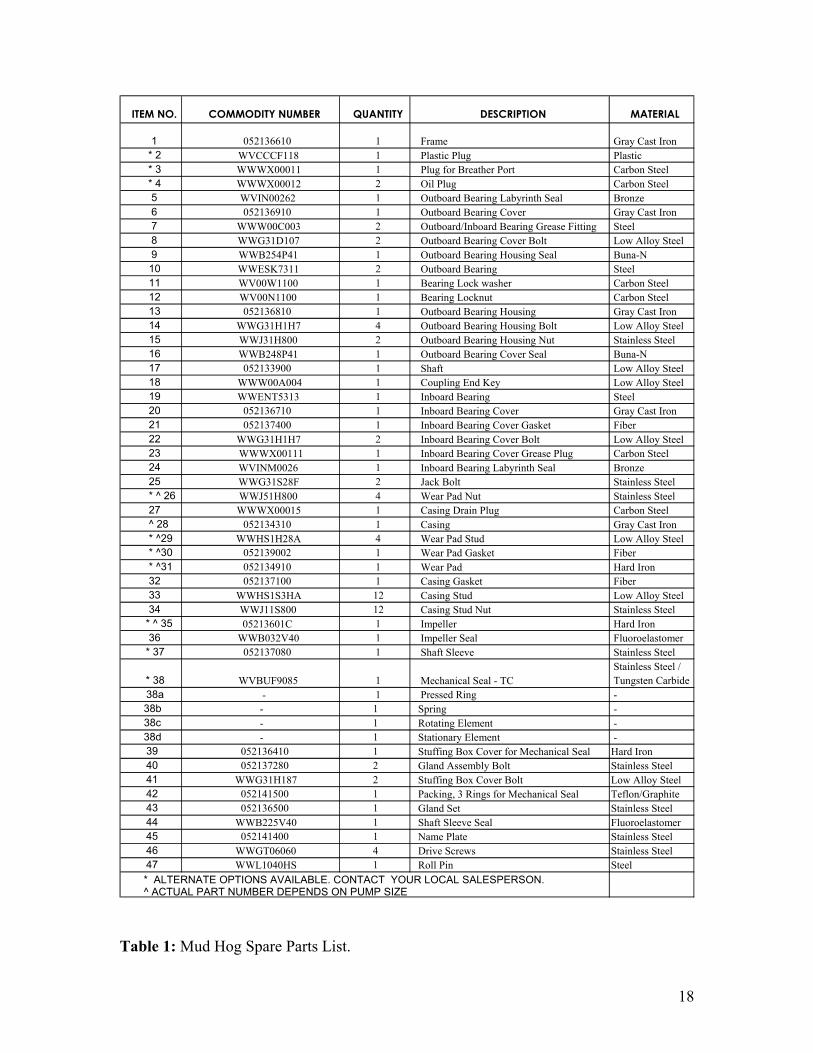
Table 1: Mud Hog Spare Parts List.
ITEM NO. COMMODITY NUMBER QUANTITY DESCRIPTION MATERIAL
1 052136610 1 Frame Gray Cast Iron* 2 WVCCCF118 1 Plastic Plug Plastic * 3 WWWX00011 1 Plug for Breather Port Carbon Steel* 4 WWWX00012 2 Oil Plug Carbon Steel5 WVIN00262 1 Outboard Bearing Labyrinth Seal Bronze 6 052136910 1 Outboard Bearing Cover Gray Cast Iron7 WWW00C003 2 Outboard/Inboard Bearing Grease Fitting Steel 8 WWG31D107 2 Outboard Bearing Cover Bolt Low Alloy Steel9 WWB254P41 1 Outboard Bearing Housing Seal Buna-N 10 WWESK7311 2 Outboard Bearing Steel 11 WV00W1100 1 Bearing Lock washer Carbon Steel12 WV00N1100 1 Bearing Locknut Carbon Steel13 052136810 1 Outboard Bearing Housing Gray Cast Iron14 WWG31H1H7 4 Outboard Bearing Housing Bolt Low Alloy Steel15 WWJ31H800 2 Outboard Bearing Housing Nut Stainless Steel16 WWB248P41 1 Outboard Bearing Cover Seal Buna-N 17 052133900 1 Shaft Low Alloy Steel18 WWW00A004 1 Coupling End Key Low Alloy Steel19 WWENT5313 1 Inboard Bearing Steel 20 052136710 1 Inboard Bearing Cover Gray Cast Iron21 052137400 1 Inboard Bearing Cover Gasket Fiber 22 WWG31H1H7 2 Inboard Bearing Cover Bolt Low Alloy Steel23 WWWX00111 1 Inboard Bearing Cover Grease Plug Carbon Steel24 WVINM0026 1 Inboard Bearing Labyrinth Seal Bronze 25 WWG31S28F 2 Jack Bolt Stainless Steel* ^ 26 WWJ51H800 4 Wear Pad Nut Stainless Steel27 WWWX00015 1 Casing Drain Plug Carbon Steel^ 28 052134310 1 Casing Gray Cast Iron* ^29 WWHS1H28A 4 Wear Pad Stud Low Alloy Steel* ^30 052139002 1 Wear Pad Gasket Fiber * ^31 052134910 1 Wear Pad Hard Iron32 052137100 1 Casing Gasket Fiber 33 WWHS1S3HA 12 Casing Stud Low Alloy Steel34 WWJ11S800 12 Casing Stud Nut Stainless Steel
* ^ 35 05213601C 1 Impeller Hard Iron36 WWB032V40 1 Impeller Seal Fluoroelastomer
* 37 052137080 1 Shaft Sleeve Stainless Steel
* 38 WVBUF9085 1 Mechanical Seal - TCStainless Steel / Tungsten Carbide
38a - 1 Pressed Ring - 38b - 1 Spring - 38c - 1 Rotating Element - 38d - 1 Stationary Element - 39 052136410 1 Stuffing Box Cover for Mechanical Seal Hard Iron 40 052137280 2 Gland Assembly Bolt Stainless Steel41 WWG31H187 2 Stuffing Box Cover Bolt Low Alloy Steel42 052141500 1 Packing, 3 Rings for Mechanical Seal Teflon/Graphite43 052136500 1 Gland Set Stainless Steel44 WWB225V40 1 Shaft Sleeve Seal Fluoroelastomer45 052141400 1 Name Plate Stainless Steel46 WWGT06060 4 Drive Screws Stainless Steel47 WWL1040HS 1 Roll Pin Steel * ALTERNATE OPTIONS AVAILABLE. CONTACT YOUR LOCAL SALESPERSON.^ ACTUAL PART NUMBER DEPENDS ON PUMP SIZE
19
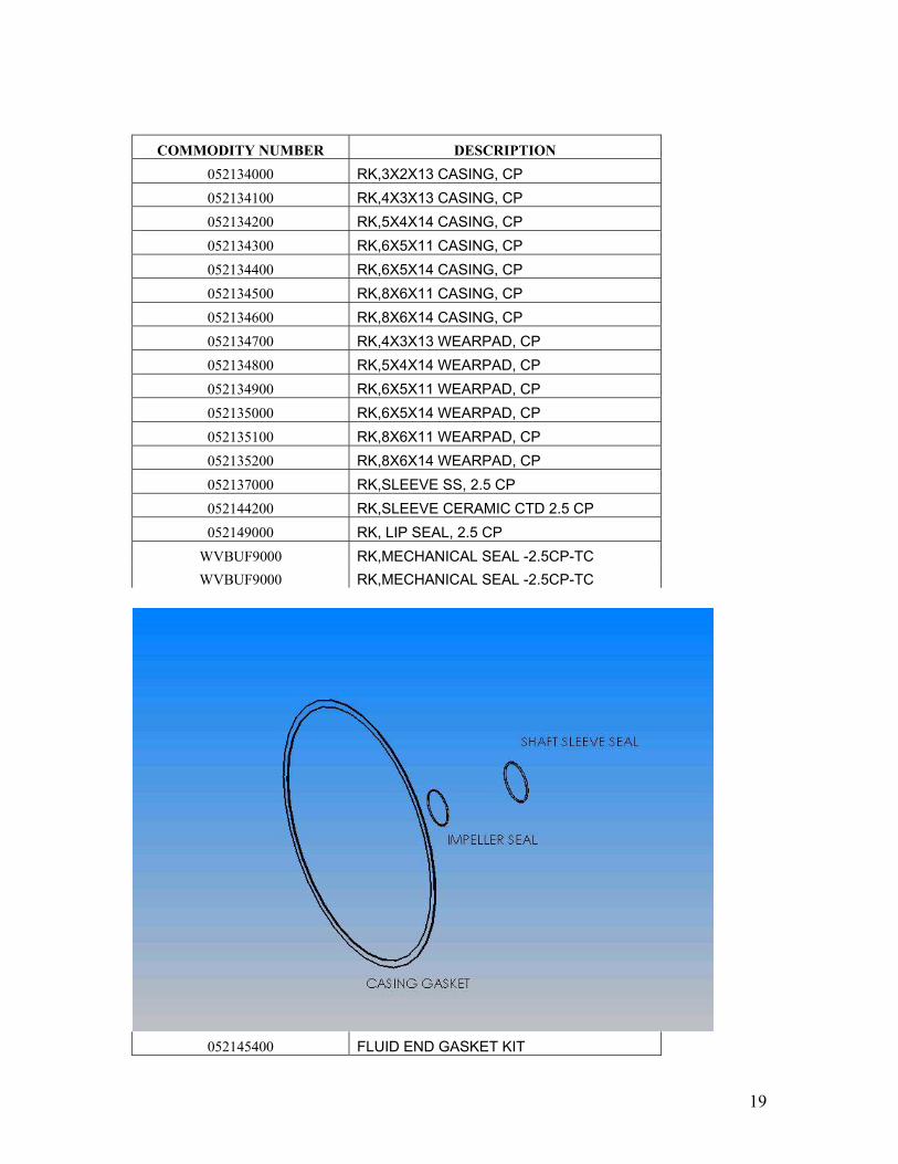
COMMODITY NUMBER DESCRIPTION 052134000 RK,3X2X13 CASING, CP 052134100 RK,4X3X13 CASING, CP 052134200 RK,5X4X14 CASING, CP 052134300 RK,6X5X11 CASING, CP 052134400 RK,6X5X14 CASING, CP 052134500 RK,8X6X11 CASING, CP 052134600 RK,8X6X14 CASING, CP 052134700 RK,4X3X13 WEARPAD, CP 052134800 RK,5X4X14 WEARPAD, CP 052134900 RK,6X5X11 WEARPAD, CP 052135000 RK,6X5X14 WEARPAD, CP 052135100 RK,8X6X11 WEARPAD, CP 052135200 RK,8X6X14 WEARPAD, CP 052137000 RK,SLEEVE SS, 2.5 CP 052144200 RK,SLEEVE CERAMIC CTD 2.5 CP 052149000 RK, LIP SEAL, 2.5 CP
WVBUF9000 RK,MECHANICAL SEAL -2.5CP-TC WVBUF9000 RK,MECHANICAL SEAL -2.5CP-TC
052145400 FLUID END GASKET KIT

20
052145500 POWER END GASKET KIT
052145600 LABYRINTH SEAL REPLACEMENT KIT
21
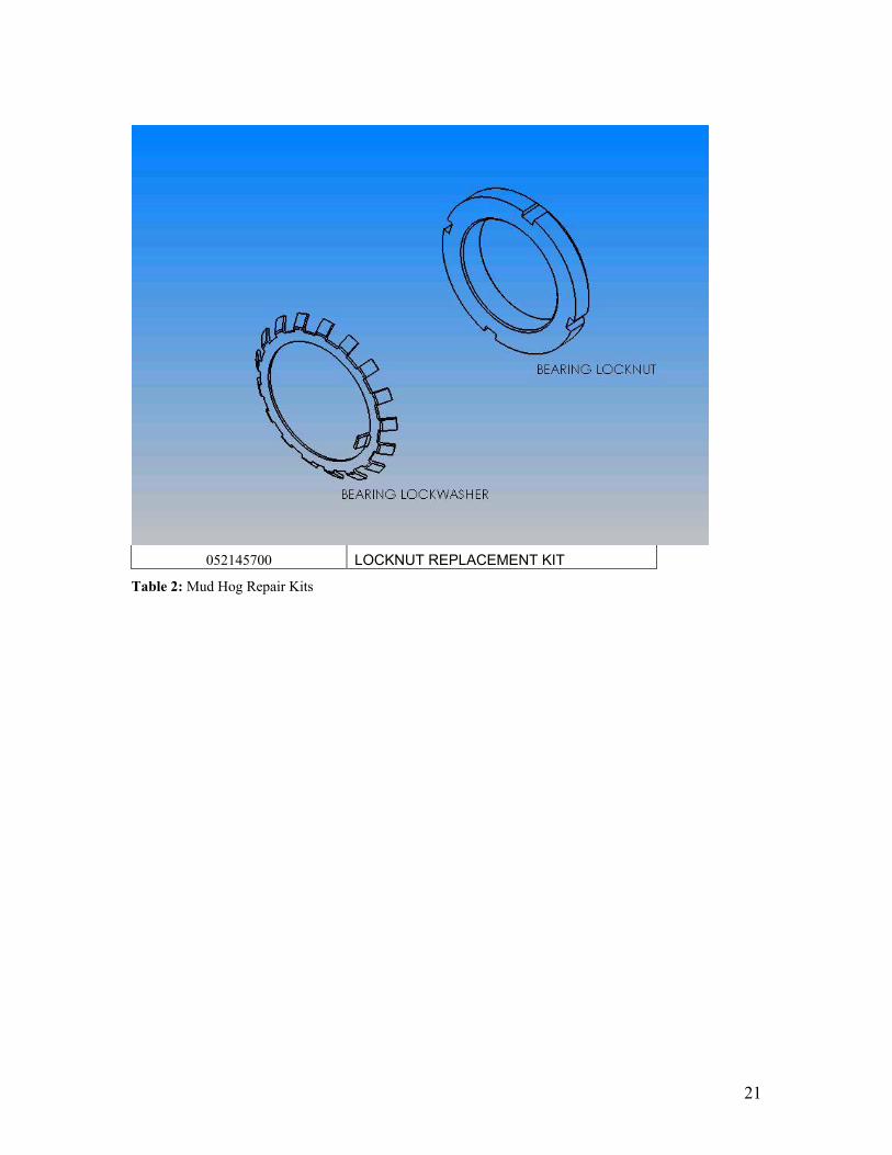
052145700 LOCKNUT REPLACEMENT KIT
Table 2: Mud Hog Repair Kits
22
Figure 6-1: Casing and parts
Figure 6-2: Frame, Stuffing Box Cover, Impeller and parts
23
Figure 6-3: Frame, Inboard Bearing Housing Cover and parts
Figure 6-4: Shaft, Bearings and parts
Revision 003 5/20/2011
Pioneer Self Priming Series ES Series
Operation & Maintenance Manual
Manual #6001
Corporate Office
310 South Sequoia Parkway Canby, OR 97013
Phone (503) 266-4115 Fax (503) 266-4116
2
TABLE of CONTENTS TABLE OF CONTENTS ........................................................................................................................................ 2
INTRODUCTION................................................................................................................................................ 3
INSPECTION ..................................................................................................................................................... 3
PRE‐INSTALLATION INSPECTION ............................................................................................................................ 3 OIL LEAKAGE CHECK ............................................................................................................................................... 4 RECORDING MODEL & SERIAL NUMBERS ............................................................................................................... 4 WARRANTY INFORMATION .................................................................................................................................... 4 SAFETY INFORMATION ........................................................................................................................................... 5
INSTALLATION ................................................................................................................................................. 6
FOUNDATION/BASE PLATE/SKID ............................................................................................................................ 6 LEVELING ................................................................................................................................................................ 6 GROUT ................................................................................................................................................................... 7 TRAILER MOUNTED UNITS ..................................................................................................................................... 7 INSTALLING PUMP ................................................................................................................................................. 7 SUCTION PIPING ..................................................................................................................................................... 7 PRODUCT FLUSH .................................................................................................................................................... 7 DISCHARGE PIPING ................................................................................................................................................. 8 SUCTION & DISCHARGE PIPE FLANGES ................................................................................................................... 8 SCREENING ............................................................................................................................................................. 9 SUMP DESIGN ........................................................................................................................................................ 9 LIFTING ................................................................................................................................................................... 9 ALIGNMENT OF PUMP AND MOTOR ...................................................................................................................... 9 ROTATION ............................................................................................................................................................ 10
OPERATION ................................................................................................................................................... 10
PRE‐START CHECK LIST ......................................................................................................................................... 10 LUBRICATION ....................................................................................................................................................... 10 PRIMING............................................................................................................................................................... 10 OPERATION OF ENGINE DRIVEN UNITS ................................................................................................................ 11 STARTING ............................................................................................................................................................. 11 ROTATION ............................................................................................................................................................... 12 LIQUID TEMPERATURE AND OVERHEATING..................................................................................................................... 12 PUMP VACUUM CHECK .............................................................................................................................................. 12 STOPPING ............................................................................................................................................................. 12
MAINTENANCE .............................................................................................................................................. 13
SPARE PARTS ........................................................................................................................................................ 13 DISASSEMBLY ....................................................................................................................................................... 15 INSPECTION COVER AND WEAR ........................................................................................................................... 15 SUCTION CHECK VALVE ........................................................................................................................................ 15 ROTATING ASSEMBLY .......................................................................................................................................... 15 IMPELLER ............................................................................................................................................................. 16 MECHANICAL SEAL ............................................................................................................................................... 16 PRESSURE RELIEF VALVE ...................................................................................................................................... 19 LUBRICATION ....................................................................................................................................................... 19
PUMP STORAGE ............................................................................................................................................. 20
TROUBLE SHOOTING ...................................................................................................................................... 20
CONDITIONS AND TERMS OF SALE ................................................................................................................. 22
3
INTRODUCTION Thank you for purchasing a Pioneer Elite Series Self-Priming centrifugal pump, complete with integral suction check valve. The pump is designed for handling non-volatile, non-flammable, mild industrial corrosives, residues and slurries containing large entrained solids. The Pioneer Elite Self-Priming Pump series is designed to be a direct bolt in replacement for the Pioneer Self-Priming Pump series.
WARNING!!! This manual provides installation, operation and maintenance instructions for your Pioneer Self-Prime Pump and is intended to make your personnel aware of any procedure that requires special attention because of potential hazards to personnel or equipment. Read all instructions carefully and remember, pump installations are seldom identical. Therefore, this manual cannot possibly provide detailed instructions and precautions for each specific application. Thus, it is the owner/installer’s responsibility to ensure that neither operator safety nor pump integrity are compromised by installations and applications that are not addressed in this manual.
WARNING!!! Centrifugal Pumps are designed for specific service and may or may not be suited for any other service without loss of performance or potential damage to equipment/personnel. If there is ever any doubt about suitability for a specific purpose; contact your Pioneer Pump, Inc. representative or the factory for assistance. Remember: Pump performance may be affected by changes in pumpage such as, specific gravity, viscosity, temperature, operating speed and net positive suction head available (NPSHA).
INSPECTION The pump assembly was inspected and tested before shipment from the factory. Before installation, inspect the pump for damage that may have occurred during shipment. PRE-INSTALLATION INSPECTION Check as follows: Inspect the pump for cracks, dents, damaged threads, and other obvious damage. Check for and tighten loose attaching hardware. Since gaskets tend to shrink after drying, check for loose hardware at mating surfaces. Carefully read all warnings and cautions contained in this manual or affixed to the pump, and perform all duties indicated. Note the direction of rotation indicated on the pump and check that the pump shaft rotates counter-clockwise when standing on the suction side of the pump and facing the impeller.
4
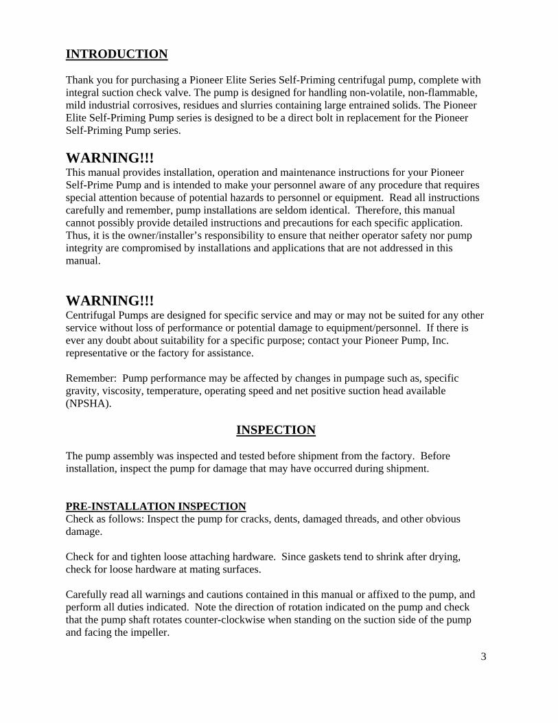
OIL LEAKAGE CHECK The bearing oil and mechanical seal oil are each sealed by a shaft lip seal, and a vent to atmosphere exists between these two lip seals to indicate oil leak from either cavity. If either the bearing oil or mechanical seal oil lip seal leaks, oil will leak from the vent. This vent should be checked for leakage prior to pump operation.
CAUTION!!! If equipment is stored more than twelve (12) months, some of the components or lubricants may have exceeded their maximum shelf life. These must be inspected and replaced as necessary prior to pump operation to ensure proper pump performance. RECORDING MODEL & SERIAL NUMBERS Record the model and serial number for your Pioneer Pump in the spaces provided below. The factory will need this information when you require parts or service.
Pump Model: _______________________________________ Pump Serial Number: ________________________________ Engine/Motor Serial #: _______________________________ Engine/Motor Mgf: __________________________________
WARRANTY INFORMATION Pioneer Pump offers the following limited warranty and method for filing warranty claims. LIMITED WARRANTY Seller warrants for one year from the date of shipment Seller’s manufactured products to the extent that Seller will replace those having defects in materials or workmanship when used for the purpose and in the manner which Seller recommends. If Seller’s examination shall disclose to its satisfaction that the products are defective, and an adjustment is required, the amount of such adjustment shall not exceed the net sales price of the defective products and no allowance will be made for labor or expense of repairing or replacing defective products or workmanship or damage resulting from the same. Seller warrants the products which it sells of other manufacturers to the extent of the warranties of their respective makers. Where engineering design or fabrication work is supplied, buyer’s acceptance of Seller’s design or of delivery of work shall relieve Seller of all further obligation, other than as expressed in Seller’s product warranty. THIS IS SELLER’S SOLE WARRANTY. NO OTHER WARRANTIES, WRITTEN OR ORAL, EXPRESS OR IMPLIED, INCLUDING THE WARRANTIES OF FITNESS FOR A PARTICULAR PURPOSE AND MERCHANTABILITY, ARE MADE OR AUTHORIZED. NO AFFIRMATION OF FACT, PROMISE,
5
DESCRIPTION OF PRODUCT OF USE OR SAMPLE OR MODEL SHALL CREATE ANY WARRANTY FROM MANUFACTURER, UNLESS SIGNED BY THE PRESIDENT OF THE MANUFACTURER. Seller neither assumes, nor authorizes any person to assume for it, any other obligation in connection with the sale of its engineering designs or products. This warranty shall not apply to any products or parts of products which (a) have been repaired or altered outside of Seller’s factory, in any manner; or (b) have been subjected to misuse, negligence or accidents; or (c) have been used in a manner contrary to Seller’s instruction or recommendations. Seller shall not be responsible for design errors due to inaccurate or incomplete information supplied by Buyer or its representative. WARRANTY CLAIMS Contact the factory to file a warranty claim, before shipping parts back. Parts returned to the factory without an RMA number on file will be scrapped upon arrival. SAFETY INFORMATION These warnings apply to Elite Series basic pumps. In many cases, Pioneer Pump, inc. has no control over or particular knowledge of the power source that will be used. Therefore, refer to the manual accompanying the power source before attempting to begin operation.
WARNING!!! Before attempting to open or service the pump:
1. Familiarize yourself with this manual. 2. Disconnect or lock out the power source to ensure that the pump will remain
inoperative. 3. Check the temperature before opening any covers, plates or plugs. 4. Allow the pump to cool if overheated. 5. Close the suction and discharge valves. 6. Vent the pump slowly and cautiously. 7. Drain the Pump.
WARNING!!! This pump is designed to handle mild industrial corrosives, residues and slurries containing large entrained solids. Do not attempt to pump volatile, corrosive, or flammable materials that may damage the pump or endanger personnel as a result of pump failure.
WARNING!!! After the pump has been positioned, make certain that the pump and all piping connections are tight, properly supported and secure before operation. (Refer to Installation section)
DANGER!!! Do not operate the pump without the guards in place over the rotating parts. Exposed rotating parts can catch clothing, fingers, or tools, causing severe injury to personnel.

6
WARNING!!! Do not remove plates, covers, gauges, pipe plugs, or fittings from an overheated pump. Vapor pressure within the pump can cause parts being disengaged to be ejected with great force. Allow the pump to cool before servicing.
WARNING!!! Do not operate the pump against a closed discharge valve for long periods of time. If operated against a closed discharge valve, pump components will deteriorate, and the liquid could come to a boil, build pressure, and cause the pump casing to rupture or explode.
WARNING!!! Remove suction and discharge piping from pump prior to moving. Use lifting and moving equipment with adequate capacity and in good repair.
INSTALLATION Use the following guidelines when installing your new Elite Series Self Priming Pump. WARNING!!! Review safety information in safety information section. This section is intended to outline general recommendations and practices required to position and arrange the pump and piping in static lift situations. If installing the unit in flooded suction applications some of the information will need to be tailored to the specific application. Never exceed the maximum permissible operating pressure of the pump as shown on the pump performance curve. FOUNDATION/BASE PLATE/SKID If using a concrete foundation it should be rigid enough to inhibit vibration. Pour the foundation well in advance of installation of pump equipment to allow time for drying and curing. If the pump is to be mounted on a steel frame, or similar structure, it should be set directly over the supporting beams. These beams and the structure must be rigid enough to prevent distortion and potential misalignment due to movement within the structure or base. The location of this structure should be as close as possible to the pumpage source. Provide adequate space for operation, maintenance and inspection of the pump and equipment. The concrete foundation should be provided with anchor bolts for attachment to the base plate. If required, provide adequate drainage to keep pump and motor dry and clean. Also, provide either leveling nuts or leveling wedges for mounting the base plate to the foundation. LEVELING When mounting the base plate to the foundation use the leveling nuts or wedges to provide a level, flat base plate. Use a machinist's level on the mounting pads and make adjustments as

7
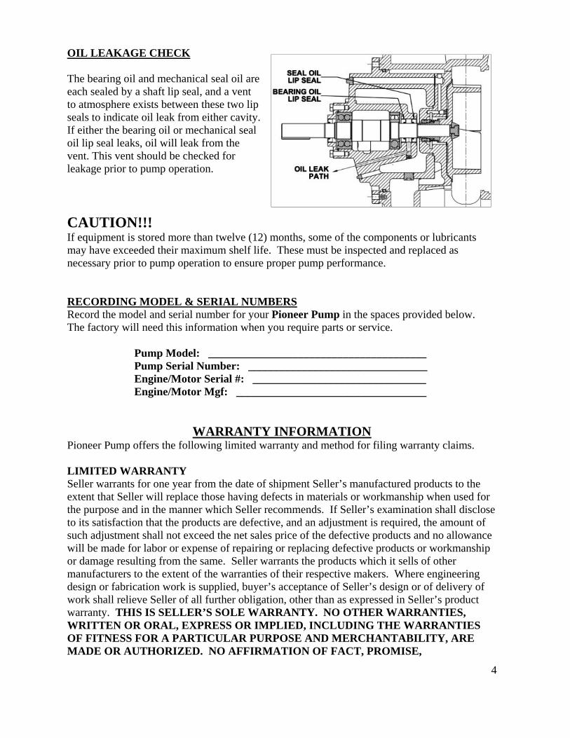
necessary as the anchor bolts are tightened. This will provide the true alignment between the pump and motor. GROUT If this base plate is to be grouted, ensure that you have the mounting surface flat and level for correct alignment of pump and motor. Build a dam around the base plate perimeter that is to be watertight. Use standard grouting practice and be sure to protect (cover) the leveling wedges with caulk or plastic tape if they are to be removed later. After the grout has thoroughly hardened, remove forms. If the wedges are removed, fill holes with grout. Seal grout by covering with a quality paint or sealer. TRAILER MOUNTED UNITS See “OPERATION” section. INSTALLING PUMP Ensure that all foreign material has been removed from the pump before mounting. Be sure to remove all shipping protection prior to operation. NOTE: Many of the bare pumps are shipped with protective guards and coatings. SUCTION PIPING For best performance the suction piping should be at least as large as the pump flange, never smaller. Use an eccentric reducer at the suction flange with the straight side up. The use of flow-retarding fittings is to be avoided and if necessary should never be placed closer to the pump suction than four (4) times the pipe diameter. The pump should be at the highest point of the piping. Slope the piping up to the pump to prevent air pockets and avoid changing pipe size with the exception of the eccentric reducer mentioned above. All suction piping and fittings are to be checked for any foreign material (rocks, bolts, wire, etc.) and also any sharp burrs that could disrupt the flow. PRODUCT FLUSH With the throttle bushing installed, remove the ½ NPT pipe plug above the shaft at the drive end of the bearing housing. Connect a water source to the ½” NPT port that maintains no less than 50% of the discharge pressure. Water will flow through the seal housing into the pumpage to keep it from entering the seal housing.
8
CAUTION!!! The suction and discharge pipe/hose material should be compatible with the liquid being pumped.
CAUTION!!! If hose is used on the suction line it should be of the reinforced type to prevent collapse under suction lift.
DANGER!!! If a manual shut-off valve is installed in the discharge line, it must not be left closed during operation, a closed manual shut off valve will cause overheating and possible explosive rupture of the pump casing. Personnel could be severely injured! DISCHARGE PIPING Use a concentric taper on the discharge side to increase discharge pipe diameters. All valving and additional fittings should be the same size as the discharge main-line. The discharge size should be adequate to maintain reasonable velocities and reduce friction losses. It is strongly recommended that a pressure relief valve is installed on the discharge piping. SUCTION & DISCHARGE PIPE FLANGES All piping is to be supported, braced and lined up square before connection to the pump flanges. A flexible fitting is recommended on both suction and discharge, to eliminate misalignment loads or stresses being transmitted to the pump. NOTE: Flexible pipe couplings must be restrained so as not to transmit any strain to the pump flanges when expanding or contracting under pressure. Unrestrained expansion fittings can transmit enormous forces to the pump flanges.

9
SCREENING Make provisions for the installation of a suction screen or strainer to prevent any debris from clogging the impeller. The open area of the strainer should be equal to at least four (4) times the area of the pipe. The screen should be rigid enough to prevent collapse when flow is reduced due to clogging. SUMP DESIGN The submergence of the suction pipe into the liquid should be at least four (4) to five (5) times the pipe diameter. If this is not possible then provide a baffle or a floating board. This is to prevent any vortex action allowing air into the pipe. For best performance a bell mouth fitting is recommended. Recommended pipe submergences for various flows as well as recommended bell diameters are shown in the table below whose data was taken from ANSI/HI 9.8-1998.
LIFTING Any lifting equipment is to be rated for at least five (5) times the weight of the item being lifted. Use only established methods when lifting or moving any heavy components. ALIGNMENT OF PUMP AND MOTOR Precise alignment is mandatory to achieve correct performance of the system. Every time a component is moved this alignment will have to be checked. The alignment can be checked with a straight edge and an outside caliper, taper thickness gauge, dial indicators, or for best results, use a laser alignment tool. Use the straight edge across the outside diameters of the coupling to ensure that the two halves are concentric and parallel. The outside calipers or the taper thickness gauge is to correct for any angular misalignment and to verify the correct gap between the coupling flanges. Use a laser alignment tool or dial indicators to adjust for concentric and angular displacement. With dial indicators, rotate shafts together and take readings every ninety (90) degrees. Make adjustments by placing shims under the driver, and be sure that the mounting bolts are properly tightened while taking readings and after final adjustment then install coupling guard.
FLOW (GPM) 500 1000 1500 2000 2500 3000 3500 4000 4500
SUBMERGENCE WITH BELL (FT)
Bell Diameter (in) 6.1 8.6 10.6 12.2 13.6 14.9 16.1 17.2 18.3
Submergence (FT) 2.1 2.6 3.0 3.3 3.5 3.7 3.9 4.1 4.3
SUBMERGENCE WITHOUT BELL (FT)
PIPE ID (in)‐ No Bell SUBMERGENCE WITHOUT BELL (FT)
3 4.7
4 3.3 6.3
6 2.1 3.7 5.3
8 1.7 2.8 3.8 4.9 6.0
10 1.6 2.3 3.1 3.8 4.6 5.4 6.1 6.9 7.6
10
ROTATION Before the pump is started correct rotation must be confirmed. If the rotation is not correct then follow the direction given by the driver manufacturer.
OPERATION
Review all safety information in the safety information section, before operating the pump. PRE-START CHECK LIST 1) Verify that rotation is correct and that the shaft rotates freely. 2) Check all piping connections for tightness. 3) Inspect all accessories and make sure they are appropriate for your installation. 4) Verify that the driver and coupling are aligned correctly and that all guards are in place. 5) Ensure that all bearings and grease seals are lubricated. 6) Oil levels should be checked and also, maintained during pump operation. 7) Follow the instruction on all tags, labels and decals attached to the equipment. 8) Review the operations manual furnished with the power source. (Equipment driver)
WARNING!!! This pump is designed to handle most non-volatile, non-flammable liquids containing specified entrained solids and corrosives. Do not attempt to pump volatile, corrosive, or flammable liquids that may damage the pump or endanger personnel as a result of pump failure.
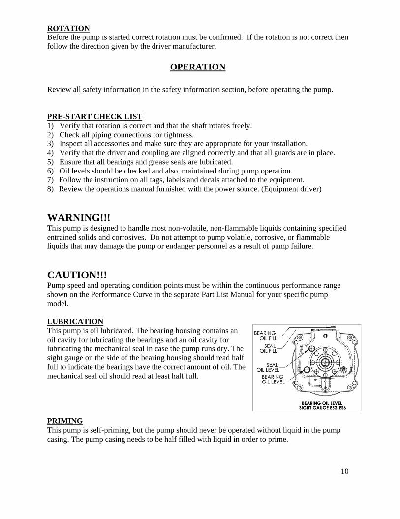
CAUTION!!! Pump speed and operating condition points must be within the continuous performance range shown on the Performance Curve in the separate Part List Manual for your specific pump model. LUBRICATION This pump is oil lubricated. The bearing housing contains an oil cavity for lubricating the bearings and an oil cavity for lubricating the mechanical seal in case the pump runs dry. The sight gauge on the side of the bearing housing should read half full to indicate the bearings have the correct amount of oil. The mechanical seal oil should read at least half full. PRIMING This pump is self-priming, but the pump should never be operated without liquid in the pump casing. The pump casing needs to be half filled with liquid in order to prime.
11
CAUTION!!! The pump will not prime when dry. Extended operation of a dry pump will destroy the seal assembly. Make sure pump casing is half filled with liquid when priming.
Add liquid to the pump casing when: 1. The liquid in the pump casing is low. 2. The pump has not been used to an extended period of time. 3. The pump is being put into service for the first time.
Once the pump casing has been filled, the pump will prime and re-prime as necessary. WARNING!!! Do not attempt to operate the pump unless all connecting piping, fill plug and other fittings are securely installed, failure to do so, could cause liquid pumped to be forced out under pressure causing injury to personnel.
WARNING!!!
Never run the pump with the discharge valve closed for extended periods of time. Never use the suction valve to throttle the flow. Check all suction and discharge piping for leaks. If a suction strainer is installed, check the pressure drop across the strainer. If the differential in pressure exceeds five (5) PSI have the strainer cleaned.
OPERATION OF ENGINE DRIVEN UNITS Review pre-start instructions in the beginning of the Operation section. Before Starting, Check the fuel level and oil levels in the engine.
CAUTION!!! Make sure the pump is level. Lower jack stands and chock the wheels. Use caution when positioning the skid-mounted unit to prevent damage to the fuel tank. Consult the engine operations manual before attempting to start the unit.
WARNING!!! Do not operate the pump without guards in place over the rotating parts. Exposed rotating parts can catch clothing, fingers or tools, causing severe injury to personnel. STARTING Consult the operations manual furnished with the power source.

12
Rotation The correct direction of pump rotation is counter-clockwise when standing on the suction side of the pump and facing the impeller. The pump could be damaged and performance adversely affected by incorrect rotation. If pump performance is not within the specified limits, verify rotation. If necessary, check the connection to the power source, and interchange two leads (three phase power) in order to change rotation. If an electric motor is used to drive the pump, remove V-belts, couplings, or otherwise disconnect the pump from the motor before checking motor rotation. Operate the motor independently while observing the direction of the motor shaft, or cooling fan. If rotation is incorrect consult the power source operation manual. Operation Open all valves in the discharge line and start the power source. Priming is indicated by a positive reading on the discharge pressure gauge or by a quieter operation. The pump may not prime immediately because the suction line must first fill with liquid. If the pump fails to prime within five minutes, stop it and check the suction line for leaks. Liquid Temperature and Overheating The maximum liquid temperature for this pump is 160º F (71º C). Do not apply it at a higher operating temperature. Overheating can occur if operated with the valves in the suction and/or discharge lines closed. Operating against closed valves could bring the liquid to a boil, build pressure, and cause the pump to rupture or explode. If overheating occurs, stop the pump and allow it to cool before servicing it. Refill the pump casing with cool liquid. As a safeguard against rupture or explosion due to heat, this pump is equipped with a pressure relief valve that will open if vapor pressure within the pump casing reaches a critical point. If overheating does occur, stop the pump immediately and allow it to cool before servicing it. Approach any overheated pump cautiously. It is recommended that the pressure relief valve assembly be replaced at each overhaul, or any time the pump casing overheats and activates the valve. Pump Vacuum Check With the pump inoperative, install a vacuum gauge in the system. Make sure the pump is at least half filled with liquid. Block the suction line and start the pump. At operating speed, the pump should pull a vacuum of 20 inches of mercury (508.0 mm) or more. If it does not, check for air leaks at the suction piping gaskets.
STOPPING Never halt the flow of liquid suddenly. If the liquid being pumped is stopped abruptly, damaging shock waves can be transmitted to the pump and piping system. Close all connecting valves slowly.
13
On engine driven pumps, reduce the throttle speed slowly and allow the engine to idle briefly before stopping. Cold Weather Protection If the pump is to remain idle during below freezing conditions, drain the pump to prevent damage from freezing. Also, clean out any solids by flushing with a hose. Bearing Temperature Check Bearings normally run at higher than ambient temperatures because of heat generated by friction. Temperatures up to 160º F (71º C) are considered normal for bearings, and they can operate safely to at least 180º F (82º C).Measure bearing temperature with a contact-type thermometer.
MAINTENANCE
Under normal conditions this pump is designed to run maintenance free, because of its rugged construction, for extended periods of time. However, all centrifugal pumps contain wear parts that will gradually deteriorate, affecting pump performance. This pump does contain wear parts and these parts should be replaced as required to maintain optimum performance. General maintenance can be performed without removing the pump from the driver. The following instructions assume a complete disassembly of the pump is required. The equipment covered in this section is limited to the pump components only. Refer to the applicable vendor's manual for motors, engines and other accessory equipment. This manual also provides a troubleshooting section to diagnose many operational or performance problems. Use the troubleshooting section to help determine the cause of any problems, and only disassemble the pump components required to remedy the problem condition. Drain volute case of pumpage when pumping unit is idle to avoid freezing and possible thermal cracking of pump case. SPARE PARTS Spare parts should be kept on hand to reduce downtime. At a minimum the following parts should be stocked.
Wear Plate All O-rings Set of bearings Mechanical seal Set of grease seals If you have unusual pumping conditions, consult Pioneer Pump, Inc. for additional recommended spare parts. When ordering parts from Pioneer Pump, Inc. please provide the following information: 1) Pump serial number 2) Pump model
14
3) Cross section drawing number 4) Part number from cross section drawing 5) Description of part 6) Quantity required 7) Package Vehicle Identification Number (VIN)
WARNING!!! Before attempting to service this pump, read this manual carefully. Operators and maintenance personnel should have a good understanding of all aspects of this pump and the pumping conditions. Failure of operating personnel to be familiar with all aspects of pump operation outlined in this manual could contribute to equipment damage, bodily injury or possible death.
WARNING!!! Before any servicing: 1) Read this manual carefully. 2) Shut down driver and lock out incoming power to ensure that the pump will remain
inoperative. 3) If the pump or components are hot, allow adequate cooling prior to servicing the unit. 4) Close the suction and discharge valves. 5) Vent the pump slowly and drain completely.
WARNING!!! If this pump is used to handle any hazardous materials that can cause illness, either directly or indirectly, take precautions by wearing approved protective clothing and use appropriate safety equipment.
WARNING!!! Use lifting and moving equipment in good repair and with adequate capacity to prevent injuries to personnel or damage to equipment. When lifting the pump with chains or cable wrapped around the pump, make certain that they are positioned so as not to damage the pump, and so that the load will be balanced. The bail on trailer or skid mounted units is intended for use in lifting the pump assembly only. Suction and discharge hoses and piping must be removed from the pump before lifting.
CAUTION!!! When servicing this pump, use only components provided by Pioneer Pump, Inc. Any use of non-authorized parts could result in sub-standard performance, damage to equipment and possible injury to personnel. Non-authorized parts will also void the warranty. When using this manual any reference to part numbers or names will be directed to the applicable cross section drawing. These parts will also be called out in the bill of materials for full description.
15
WARNING!!! Select a clean suitable location for any required maintenance, and note that all work must be performed by qualified personnel.
DISASSEMBLY Before performing maintenance on your pump, verify the following:
1. Driver is shut down and power is locked out. 2. If pump components are hot, allow to adequately cool. 3. Suction and discharge valves are shut. 4. Drain pump after it has adequately cooled. 5. For power source maintenance refer to power source O & M manual. 6. Review all safety information and follow the instructions in this manual, as well as, all
tags, labels and decals attached to the pump or related equipment.
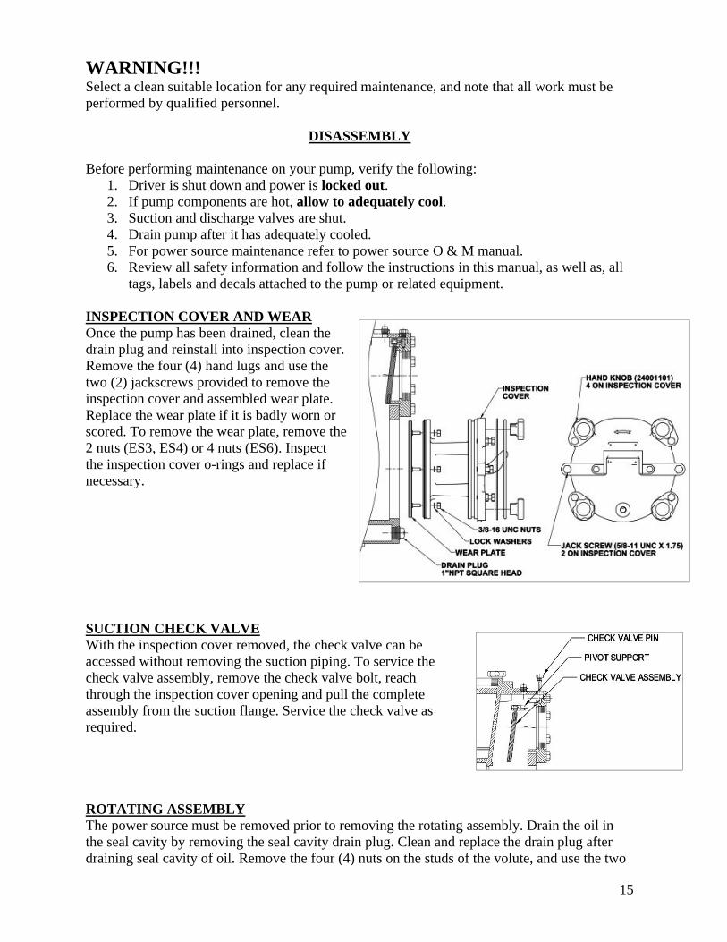
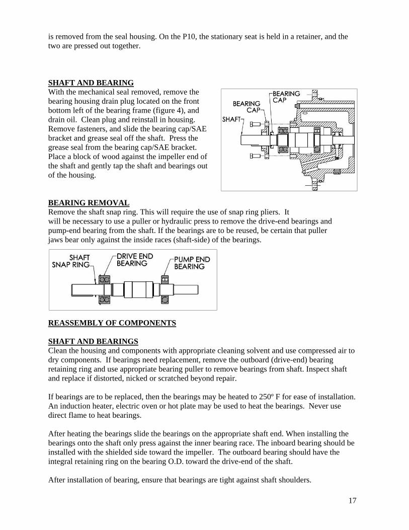
INSPECTION COVER AND WEAR Once the pump has been drained, clean the drain plug and reinstall into inspection cover. Remove the four (4) hand lugs and use the two (2) jackscrews provided to remove the inspection cover and assembled wear plate. Replace the wear plate if it is badly worn or scored. To remove the wear plate, remove the 2 nuts (ES3, ES4) or 4 nuts (ES6). Inspect the inspection cover o-rings and replace if necessary. SUCTION CHECK VALVE With the inspection cover removed, the check valve can be accessed without removing the suction piping. To service the check valve assembly, remove the check valve bolt, reach through the inspection cover opening and pull the complete assembly from the suction flange. Service the check valve as required. ROTATING ASSEMBLY The power source must be removed prior to removing the rotating assembly. Drain the oil in the seal cavity by removing the seal cavity drain plug. Clean and replace the drain plug after draining seal cavity of oil. Remove the four (4) nuts on the studs of the volute, and use the two

16
(2) jackscrews to remove the rotating assembly from the volute. Separate the rotating assembly by pulling straight away from the pump casing.
IMPELLER With the rotating assembly removed from the pump casing, remove the impeller lock screw and unscrew the impeller from the shaft. The impeller was installed at the factory using Loctite® and so may be fairly difficult to unscrew. A propane torch can be used to ease loosening the screw if necessary. Use the impeller removal tool to fix the shaft from rotating, and use a metal bar or piece of wood to rotate the impeller counter-clockwise until it is free of the shaft. It may be necessary to pound the bar with a hammer to loosen the impeller. Inspect the impeller and replace as necessary. Use caution when removing the impeller.
MECHANICAL SEAL With the rotating assembly out of the volute and the impeller removed, slide the shaft sleeve and rotating portion of the seal off of the shaft as one unit (3” to 8” pumps). On the P10 there is no sleeve or sleeve o-ring. Drain the oil in the seal cavity by removing the seal cavity drain plug, located on the bearing housing’s bottom front boss (figure 4). Clean and replace the drain plug after draining seal cavity of oil. Remove the seal housing from the bearing frame, and place it, face down, on a flat surface. With a suitable tool press on the backside of the stationary seat until it
17
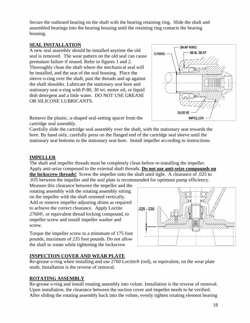
is removed from the seal housing. On the P10, the stationary seat is held in a retainer, and the two are pressed out together. SHAFT AND BEARING With the mechanical seal removed, remove the bearing housing drain plug located on the front bottom left of the bearing frame (figure 4), and drain oil. Clean plug and reinstall in housing. Remove fasteners, and slide the bearing cap/SAE bracket and grease seal off the shaft. Press the grease seal from the bearing cap/SAE bracket. Place a block of wood against the impeller end of the shaft and gently tap the shaft and bearings out of the housing. BEARING REMOVAL Remove the shaft snap ring. This will require the use of snap ring pliers. It will be necessary to use a puller or hydraulic press to remove the drive-end bearings and pump-end bearing from the shaft. If the bearings are to be reused, be certain that puller jaws bear only against the inside races (shaft-side) of the bearings.
REASSEMBLY OF COMPONENTS SHAFT AND BEARINGS Clean the housing and components with appropriate cleaning solvent and use compressed air to dry components. If bearings need replacement, remove the outboard (drive-end) bearing retaining ring and use appropriate bearing puller to remove bearings from shaft. Inspect shaft and replace if distorted, nicked or scratched beyond repair. If bearings are to be replaced, then the bearings may be heated to 250º F for ease of installation. An induction heater, electric oven or hot plate may be used to heat the bearings. Never use direct flame to heat bearings. After heating the bearings slide the bearings on the appropriate shaft end. When installing the bearings onto the shaft only press against the inner bearing race. The inboard bearing should be installed with the shielded side toward the impeller. The outboard bearing should have the integral retaining ring on the bearing O.D. toward the drive-end of the shaft. After installation of bearing, ensure that bearings are tight against shaft shoulders.
18
Secure the outboard bearing on the shaft with the bearing retaining ring. Slide the shaft and assembled bearings into the bearing housing until the retaining ring contacts the bearing housing. SEAL INSTALLATION A new seal assembly should be installed anytime the old seal is removed. The wear pattern on the old seal can cause premature failure if reused. Refer to figures 1 and 2. Thoroughly clean the shaft where the mechanical seal will be installed, and the seat of the seal housing. Place the sleeve o-ring over the shaft, past the threads and up against the shaft shoulder. Lubricate the stationary seat bore and stationary seat o-ring with P-80, 30 wt. motor oil, or liquid dish detergent and a little water. DO NOT USE GREASE OR SILICONE LUBRICANTS. Remove the plastic, u-shaped seal-setting spacer from the cartridge seal assembly. Carefully slide the cartridge seal assembly over the shaft, with the stationary seat towards the bore. By hand only, carefully press on the flanged end of the cartridge seal sleeve until the stationary seat bottoms in the stationary seat bore. Install impeller according to instructions. IMPELLER The shaft and impeller threads must be completely clean before re-installing the impeller. Apply anti-seize compound to the external shaft threads. Do not use anti-seize compounds on the lockscrew threads! Screw the impeller onto the shaft until tight. A clearance of .025 to .035 between the impeller and the seal plate is recommended for optimum pump efficiency. Measure this clearance between the impeller and the rotating assembly with the rotating assembly sitting on the impeller with the shaft oriented vertically. Add or remove impeller adjusting shims as required to achieve the correct clearance. Apply Loctite 2760, or equivalent thread locking compound, to impeller screw and install impeller washer and screw.
Torque the impeller screw to a minimum of 175 foot pounds, maximum of 235 foot pounds. Do not allow the shaft to rotate while tightening the lockscrew INSPECTION COVER AND WEAR PLATE Re-grease o-ring when installing and use 2760 Loctite® (red), or equivalent, on the wear plate studs. Installation is the reverse of removal. ROTATING ASSEMBLY Re-grease o-ring and install rotating assembly into volute. Installation is the reverse of removal. Upon installation, the clearance between the suction cover and impeller needs to be verified. After sliding the rotating assembly back into the volute, evenly tighten rotating element bearing

19
housing fasteners until impeller lightly contacts wear plate. Note: the shaft will not rotate. Tighten bearing housing jack screws until .010” to .020” increase in clearance is achieved. .010” to .020” is the desired clearance between the impeller and wear plate. This can be determined by taking measurements of the gap between the pump casing and the bearing housing when the impeller is making contact with the wear plate, then re-measure the same gap until the above increase in clearance is achieved at each corner of the bearing housing. Rotate shaft, making sure there isn’t any impeller/wear plate contact or rubbing. Tighten the jack screws at each corner of the bearing housing (not too tight), then tighten the jackscrew lock nuts to maintain setting position. Rotate shaft to verify the shaft is free to rotate without the impeller rubbing on the wear plate after adjustment. If the impeller continues to rub on the wear plate, repeat adjustment procedure above until the shaft rotates freely. INSPECTION COVER AND WEAR PLATE ADJUSTMENT (ES3 THROUGH ES6 ) The wear plate clearance can be opened on the ES- series without removing the rotating assembly by loosening the four (4) hand knobs and tightening the four (4) jack screws. Then re-tighten the hand knobs. The adjustment distance can be measured by comparing the before and after gap between the adjustment flange and the volute casing. PRESSURE RELIEF VALVE The suction cover is equipped with a pressure relief valve to provide additional safety for the pump and operator. Make sure the relief valve is set to 80 psi
DANGER!!! It is recommended that the pressure relief valve assembly be replaced at each overhaul, or any time the pump overheats and activates the valve. Periodically, the valve should be removed for inspection and cleaning. LUBRICATION Proper lubrication is essential to maintain performance and to help ensure trouble free operation. Seal Assembly Prior to starting the pump, remove the seal vent plug and fill the seal cavity with approximately 1 quart of ISO VG 32 viscosity grade 32 Turbine oil, so that the oil level is halfway in the level sight gauge.
Bearings The bearing housing was lubricated at the factory and should be maintained at the middle of the sight gauge. Use an ISO viscosity grade 32 Turbine oil and fill through the air vent hole at the
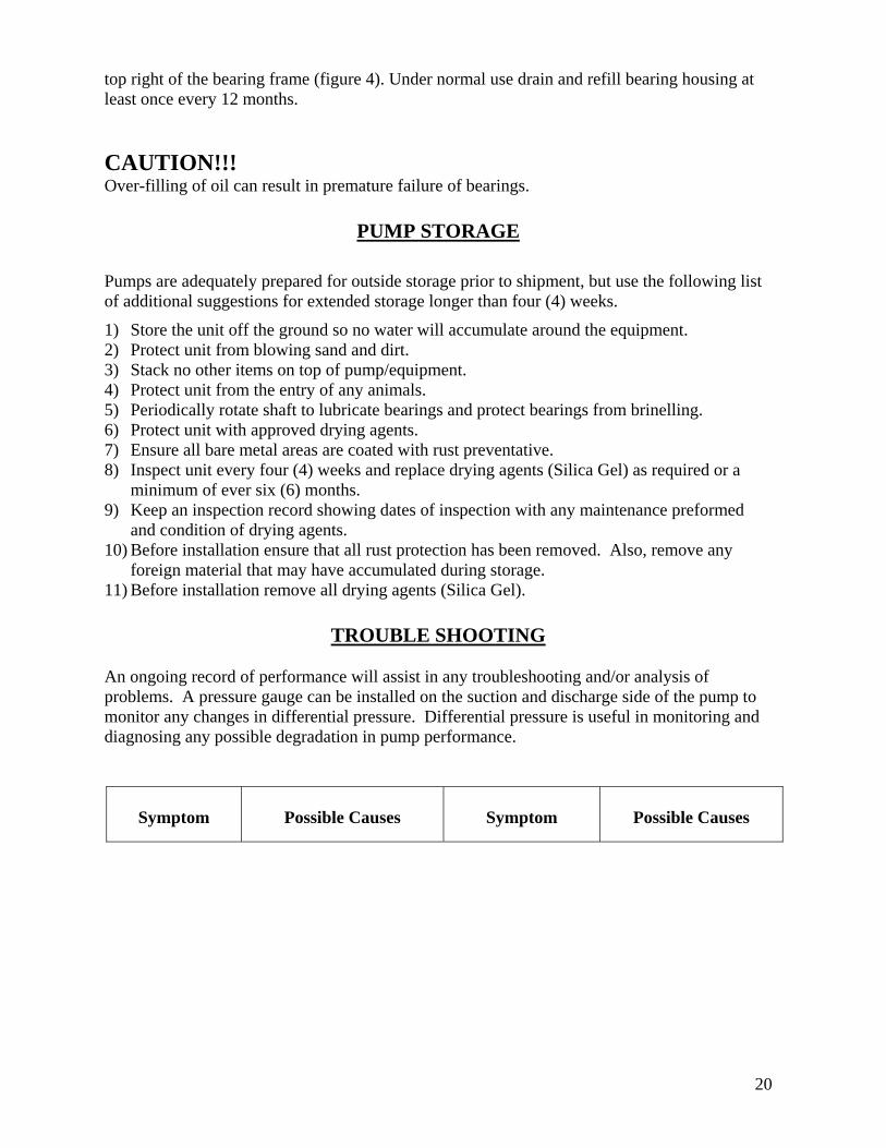
20
top right of the bearing frame (figure 4). Under normal use drain and refill bearing housing at least once every 12 months.
CAUTION!!! Over-filling of oil can result in premature failure of bearings.
PUMP STORAGE
Pumps are adequately prepared for outside storage prior to shipment, but use the following list of additional suggestions for extended storage longer than four (4) weeks.
1) Store the unit off the ground so no water will accumulate around the equipment. 2) Protect unit from blowing sand and dirt. 3) Stack no other items on top of pump/equipment. 4) Protect unit from the entry of any animals. 5) Periodically rotate shaft to lubricate bearings and protect bearings from brinelling. 6) Protect unit with approved drying agents. 7) Ensure all bare metal areas are coated with rust preventative. 8) Inspect unit every four (4) weeks and replace drying agents (Silica Gel) as required or a
minimum of ever six (6) months. 9) Keep an inspection record showing dates of inspection with any maintenance preformed
and condition of drying agents. 10) Before installation ensure that all rust protection has been removed. Also, remove any
foreign material that may have accumulated during storage. 11) Before installation remove all drying agents (Silica Gel).
TROUBLE SHOOTING
An ongoing record of performance will assist in any troubleshooting and/or analysis of problems. A pressure gauge can be installed on the suction and discharge side of the pump to monitor any changes in differential pressure. Differential pressure is useful in monitoring and diagnosing any possible degradation in pump performance.
Symptom
Possible Causes
Symptom
Possible Causes
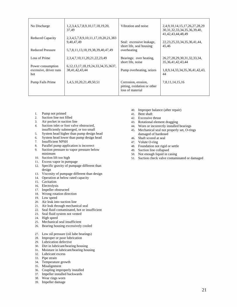
21
No Discharge Reduced Capacity Reduced Pressure Loss of Prime Power consumption excessive, driver runs hot Pump Fails Prime
1,2,3,4,5,7,8,9,10,17,18,19,20, 37,49 2,3,4,5,7,8,9,10,11,17,19,20,21,3839,40,47,49 5,7,8,11,13,18,19,38,39,40,47,49 2,3,4,7,10,11,20,21,22,23,49 6,12,13,17,18,19,24,33,34,35,3637,38,41,42,43,44 1,4,5,10,20,21,49,50,51
Vibration and noise Seal: excessive leakage, short life, seal housing overheating Bearings: over heating, short life, noise Pump overheating, seizes Corrosion, erosion, pitting, oxidation or other loss of material
2,4,9,10,14,15,17,26,27,28,29 30,31,32,33,34,35,36,39,40, 41,42,43,44,48,49 22,23,25,33,34,35,36,41,44, 45,46 26,27,28,29,30,31,32,33,34, 35,36,41,42,43,44 1,8,9,14,33,34,35,36,41,42,43, 44 7,8,11,14,15,16
1. Pump not primed 2. Suction line not filled 3. Air pocket in suction line 4. Suction inlet or foot valve obstructed,
insufficiently submerged, or too small 5. System head higher than pump design head 6. System head lower than pump design head 7. Insufficient NPSH 8. Parallel pump application is incorrect 9. Suction pressure to vapor pressure below
minimum 10. Suction lift too high 11. Excess vapor in pumpage 12. Specific gravity of pumpage different than
design 13. Viscosity of pumpage different than design 14. Operation at below rated capacity 15. Cavitation 16. Electrolysis 17. Impeller obstructed 18. Wrong rotation direction 19. Low speed 20. Air leak into suction line 21. Air leak through mechanical seal 22. Seal fluid contaminated, hot or insufficient 23. Seal fluid system not vented 24. High speed 25. Mechanical seal insufficient 26. Bearing housing excessively cooled
27. Low oil pressure (oil lube bearings) 28. Improper or poor lubrication 29. Lubrication defective 30. Dirt in lubricant/bearing housing 31. Moisture in lubricant/bearing housing 32. Lubricant excess 33. Pipe strain 34. Temperature growth 35. Misalignment 36. Coupling improperly installed 37. Impeller installed backwards 38. Wear rings worn 39. Impeller damage
40. Improper balance (after repair) 41. Bent shaft 42. Excessive thrust 43. Rotational element dragging 44. Worn or incorrectly installed bearings 45. Mechanical seal not properly set, O-rings
damaged of hardened 46. Shaft scored at seal 47. Volute O-ring 48. Foundation not rigid or settle 49. Suction line collapsed 50. Not enough liquid in casing 51. Suction check valve contaminated or damaged
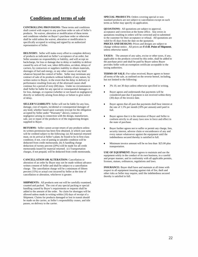
22
Conditions and terms of sale CONTROLLING PROVISIONS: These terms and conditions shall control with respect to any purchase order or sale of Seller’s products. No waiver, alteration or modification of these terms and conditions whether on Buyer’s purchase order or otherwise shall be valid unless the waiver, alteration or modification is specifically accepted in writing and signed by an authorized representative of Seller.
DELIVERY: Seller will make every effort to complete delivery of products as indicated on Seller’s acceptance of an order, but Seller assumes no responsibility or liability, and will accept no backcharge, for loss or damage due to delay or inability to deliver caused by acts of God, war, labor difficulties, accident, delays of carriers, by contractors or suppliers inability to obtain materials, shortages of fuel and energy, or any other causes of any kind whatever beyond the control of Seller. Seller may terminate any contract of sale of its products without liability of any nature, by written notice to Buyer, in the event that the delay in delivery or performance resulting from any of the aforesaid causes shall continue for a period of sixty (60) days. Under no circumstances shall Seller be liable for any special or consequential damages or for loss, damage, or expense (whether or not based on negligence) directly or indirectly arising from delays or failure to give notice of delay. SELLER’S LIABILITY: Seller will not be liable for any loss, damage, cost of repairs, incidental or consequential damages of any kind, whether based upon warranty (except for the obligation accepted by Seller under “Warranty” above), contract or negligence arising in connection with the design, manufacture, sale, use or repair of the products or of the engineering designs supplied to Buyer. RETURNS: Seller cannot accept return of any products unless its written permission has been first obtained, in which case same will be credited subject to the following: (a) All material returned must, on its arrival at Seller’s plant, be found to be in first-class condition; if not, cost of putting in saleable condition will be deducted from credit memoranda. (b) A handling charge deduction of twenty percent (20%) will be made for all credit memoranda issued for material returned. (c) Transportation charges, if not prepaid, will be deducted from credit memoranda.
CANCELLATION OR ALTERATION: Cancellation or alteration of an order by Buyer may not be made without advance written consent of Seller and shall be subject to a cancellation charge. The cancellation charge will be a minimum of fifteen percent (15%) or actual cost incurred by Seller at the time of cancellation or alteration, whichever is greater.
SHIPMENTS: All products sent out will be carefully examined, counted and packed. The cost of any special packing or special handling caused by Buyer’s requirements or requests shall be added to the amount of the order. No claim for shortages will be allowed unless made in writing within (10) days of receipt of a Shipment. Claims for products damaged or lost in transit should be made on the carrier, as Seller’s responsibility ceases, and title passes, on delivery to the carrier.
SPECIAL PRODUCTS: Orders covering special or non-standard products are not subject to cancellation except on such terms as Seller may specify on application. QUOATIONS: All quotations are subject to approval, acceptance and correction at the home office. Any errors in quotations resulting in orders will be corrected and re-submitted to the customer for their acceptance or refusal. All quotations are valid for 45 days from the date on the quotation. PRICES AND DESIGNS: Prices and designs are subject to change without notice. All prices are F.O.B. Point of Shipment, unless otherwise stated. TAXES: The amount of any sales, excise or other taxes, if any, applicable to the products covered by this order, shall be added to the purchase price and shall be paid by Buyer unless Buyer provides Seller with an exemption certificate acceptable to the taxing authorities. TERMS OF SALE: For value received, Buyer agrees to honor all terms of the sale, as outlined on the reverse hereof, including, but not limited to the following: 3% 10, net 30 days unless otherwise specified in writing. Buyer agrees and understands that payments will be
considered past due if payment is not received within thirty (30) days of the invoice date.
Buyer agrees that all past due payments shall bear interest at
the rate of 1.5% per month (18% per annum) until paid in full.
Buyer agrees that it is the intention of Buyer and Seller to
conform strictly to all usury laws now in force and effect in the state of purchase.
Buyer further agrees not to suffer or permit any charge, lien,
security interest, adverse claim or encumbrance of any and every nature whatsoever against the equipment until the indebtedness secured thereby is satisfied in full.
Minimum invoice amount will be no less than $25.00 plus
transportation. USE OF EQUIPMENT: Buyer agrees to maintain and use the equipment solely in the conduct of its own business, in a careful and proper manner, and in conformity with all applicable permits, licenses, statues, ordinances, regulations and laws. INSURANCE: Buyer shall have and maintain at all times with respect to all equipment insuring against risk of fire, theft and other risks as Seller may require, until the indebtedness secured thereby is satisfied in full.
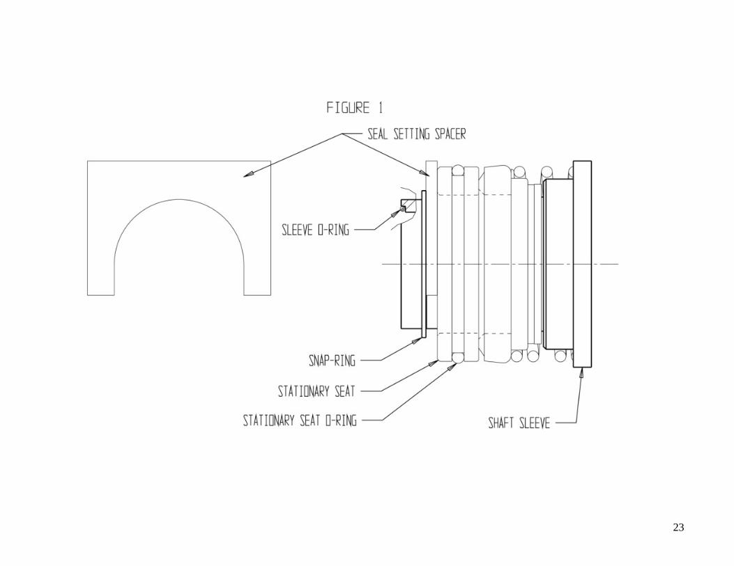
23
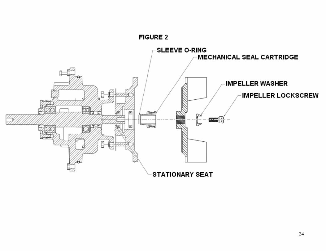
24