Development of a Centralized Electronic Lock...
62
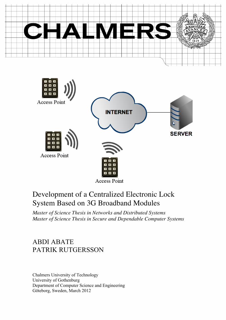
Chalmers University of Technology University of Gothenburg Department of Computer Science and Engineering Göteborg, Sweden, March 2012 Development of a Centralized Electronic Lock System Based on 3G Broadband Modules Master of Science Thesis in Networks and Distributed Systems Master of Science Thesis in Secure and Dependable Computer Systems ABDI ABATE PATRIK RUTGERSSON
Transcript of Development of a Centralized Electronic Lock...
Chalmers University of Technology University of Gothenburg Department of Computer Science and Engineering Göteborg, Sweden, March 2012
Development of a Centralized Electronic Lock System Based on 3G Broadband Modules Master of Science Thesis in Networks and Distributed Systems Master of Science Thesis in Secure and Dependable Computer Systems ABDI ABATE PATRIK RUTGERSSON
The Author grants to Chalmers University of Technology and University of Gothenburg the non-exclusive right to publish the Work electronically and in a non-commercial purpose make it accessible on the Internet. The Author warrants that he/she is the author to the Work, and warrants that the Work does not contain text, pictures or other material that violates copyright law. The Author shall, when transferring the rights of the Work to a third party (for example a publisher or a company), acknowledge the third party about this agreement. If the Author has signed a copyright agreement with a third party regarding the Work, the Author warrants hereby that he/she has obtained any necessary permission from this third party to let Chalmers University of Technology and University of Gothenburg store the Work electronically and make it accessible on the Internet. Development of a Centralized Electronic Lock System Based on 3G Broadband Modules ABDI ABATE PATRIK RUTGERSSON © ABDI ABATE, March 2012. © PATRIK RUTGERSSON, March 2012. Examiner: TOMAS OLOVSSON Chalmers University of Technology University of Gothenburg Department of Computer Science and Engineering SE-412 96 Göteborg Sweden Telephone + 46 (0)31-772 1000 Cover: An overview of the developed system. Department of Computer Science and Engineering Göteborg, Sweden March 2012
Abstract
Ericsson’s 3G Broadband modules are primarly intended for laptops, but they are perfectin terms of size for being used in other electronic devices. Therefore, the purpose of thismaster’s thesis is to develop a demo system for Ericsson’s 3G Broadband modules. Wehave developed an electronic lock system consisting of a large number of access pointstalking to a centralized server. The server handles the access control and is contacted everytime a user wants to get access to an electronic lock. The electronic locks, called accesspoints, need 3G modules to be able to communicate with the server over the Internet.The communication within the system is encrypted with SSH and pin codes are used toidentify different users. The developed system became a well-functional electronic locksystem.
i

Acknowledgements
We would like to thank the employees at Ericsson for the help they have given us. Aspecial thank to our supervisors, Erika Asp and Thorbjörn Larsson, for all feedback andsuggestions throughout the project. We would also like to thank our examiner at ChalmersUniversity of Technology, Tomas Olovsson, for his valuable feedback on the report.
ii
Table of Contents
1 Introduction 11.1 Related Work . . . . . . . . . . . . . . . . . . . . . . . . . . . . . . . . 11.2 Problem Description . . . . . . . . . . . . . . . . . . . . . . . . . . . . 21.3 Limitations . . . . . . . . . . . . . . . . . . . . . . . . . . . . . . . . . 21.4 Outline of the thesis . . . . . . . . . . . . . . . . . . . . . . . . . . . . . 3
2 System Overview 42.1 Access Point . . . . . . . . . . . . . . . . . . . . . . . . . . . . . . . . . 42.2 Server . . . . . . . . . . . . . . . . . . . . . . . . . . . . . . . . . . . . 5
3 Technical Description 73.1 Hardware Related . . . . . . . . . . . . . . . . . . . . . . . . . . . . . . 7
3.1.1 Matrix Keypad . . . . . . . . . . . . . . . . . . . . . . . . . . . 73.1.2 Serial Peripheral Interface (SPI) . . . . . . . . . . . . . . . . . . 8
3.2 Software Related . . . . . . . . . . . . . . . . . . . . . . . . . . . . . . 93.2.1 AT Commands . . . . . . . . . . . . . . . . . . . . . . . . . . . 93.2.2 BuildRoot . . . . . . . . . . . . . . . . . . . . . . . . . . . . . . 93.2.3 Cross-Compiling . . . . . . . . . . . . . . . . . . . . . . . . . . 103.2.4 Model-View-Controller (MVC) . . . . . . . . . . . . . . . . . . 103.2.5 NMEA 0183 . . . . . . . . . . . . . . . . . . . . . . . . . . . . 103.2.6 Protocol Buffers . . . . . . . . . . . . . . . . . . . . . . . . . . 103.2.7 Role-Based Access Control (RBAC) . . . . . . . . . . . . . . . . 113.2.8 Sysfs . . . . . . . . . . . . . . . . . . . . . . . . . . . . . . . . 12
4 Technical Choices 144.1 Development Board . . . . . . . . . . . . . . . . . . . . . . . . . . . . . 144.2 Handling Users . . . . . . . . . . . . . . . . . . . . . . . . . . . . . . . 144.3 Programming Languages . . . . . . . . . . . . . . . . . . . . . . . . . . 154.4 Communication Between Server and Access Points . . . . . . . . . . . . 154.5 SSH vs IPSec . . . . . . . . . . . . . . . . . . . . . . . . . . . . . . . . 164.6 Keypad Construction . . . . . . . . . . . . . . . . . . . . . . . . . . . . 16
5 Hardware 175.1 Ericsson’s 3G Broadband Module . . . . . . . . . . . . . . . . . . . . . 17
5.1.1 AT Commands . . . . . . . . . . . . . . . . . . . . . . . . . . . 185.1.2 Firmware Updates . . . . . . . . . . . . . . . . . . . . . . . . . 18
iii
5.2 Keypad Connection . . . . . . . . . . . . . . . . . . . . . . . . . . . . . 19
6 Configuring the Development Board 216.1 Building a Customized Linux Kernel . . . . . . . . . . . . . . . . . . . . 21
6.1.1 Kernel Patch . . . . . . . . . . . . . . . . . . . . . . . . . . . . 226.1.2 Kernel Configuration . . . . . . . . . . . . . . . . . . . . . . . . 24
6.2 Setting Up an SD Card . . . . . . . . . . . . . . . . . . . . . . . . . . . 256.2.1 Moving files to the SD Card . . . . . . . . . . . . . . . . . . . . 25
6.3 Booting the Kernel Using U-Boot . . . . . . . . . . . . . . . . . . . . . 26
7 Software 277.1 Communication between Server and Access Point . . . . . . . . . . . . . 27
7.1.1 Limit the Traffic in the System . . . . . . . . . . . . . . . . . . . 277.1.2 Protocol Buffers Messages . . . . . . . . . . . . . . . . . . . . . 287.1.3 The Order of the Messages . . . . . . . . . . . . . . . . . . . . . 317.1.4 Sending Subsequent Messages . . . . . . . . . . . . . . . . . . . 317.1.5 Encrypted Communication . . . . . . . . . . . . . . . . . . . . . 327.1.6 Sending Firmware Updates . . . . . . . . . . . . . . . . . . . . . 32
7.2 Access Point Software . . . . . . . . . . . . . . . . . . . . . . . . . . . 327.2.1 Program Flow . . . . . . . . . . . . . . . . . . . . . . . . . . . . 327.2.2 Communicating with 3G Broadband Module . . . . . . . . . . . 337.2.3 Connecting to the Internet . . . . . . . . . . . . . . . . . . . . . 337.2.4 SSH Tunnel . . . . . . . . . . . . . . . . . . . . . . . . . . . . . 347.2.5 Reading User Input From Keypad . . . . . . . . . . . . . . . . . 357.2.6 Access Point Locked or Unlocked . . . . . . . . . . . . . . . . . 377.2.7 Inactivation of the Access Point . . . . . . . . . . . . . . . . . . 377.2.8 Getting and Formatting the GPS Data . . . . . . . . . . . . . . . 377.2.9 Updating the Firmware of a Module . . . . . . . . . . . . . . . . 38
7.3 Server Software . . . . . . . . . . . . . . . . . . . . . . . . . . . . . . . 397.3.1 Application implemented in MVC . . . . . . . . . . . . . . . . . 397.3.2 Using a Database to Save Information . . . . . . . . . . . . . . . 397.3.3 Handling Connections From Access Points . . . . . . . . . . . . 407.3.4 Handling Users and Their Permissions . . . . . . . . . . . . . . . 427.3.5 Firmware Updates . . . . . . . . . . . . . . . . . . . . . . . . . 45
7.4 Software-Based Access Point . . . . . . . . . . . . . . . . . . . . . . . . 45
8 Summary 47
9 Discussion and Conclusions 49
10 Future Work 51
References 52
A AT Commands 55
iv
List of Figures
2.1 An overview of the system. . . . . . . . . . . . . . . . . . . . . . . . . . 42.2 The access point that was developed. . . . . . . . . . . . . . . . . . . . . 5
3.1 A schematic of a keypad. (Figure from [11]) . . . . . . . . . . . . . . . . 73.2 One master is talking to several slave devices over SPI. (Figure from [12]) 8
4.1 BeagleBoard-xM Rev. C. . . . . . . . . . . . . . . . . . . . . . . . . . . 14
5.1 An Ericsson F5521gw module. . . . . . . . . . . . . . . . . . . . . . . . 175.2 A cradle that the 3G Broadband module is placed in. . . . . . . . . . . . 185.3 Connection of keypad to the BeagleBoard through a SPI to GPIO expander. 19
7.1 Illustration of a message and its size in a buffer. . . . . . . . . . . . . . . 317.2 Flowchart explaining the program flow of the access point. . . . . . . . . 337.3 Flowchart explaining how an Internet connection is set up. . . . . . . . . 347.4 How key presses are recognized. In A, no keys are pressed and all column
values are ’1’. In B, key ’1’ is pressed and therefore col 1 gets the valueof row 1. . . . . . . . . . . . . . . . . . . . . . . . . . . . . . . . . . . . 36
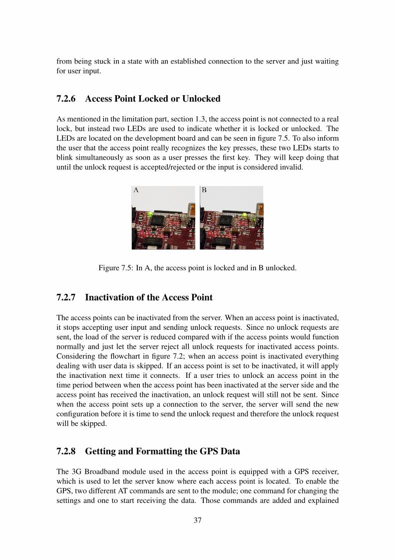
7.5 In A, the access point is locked and in B unlocked. . . . . . . . . . . . . 377.6 Entity-Relation diagram over the database used in the lock system. . . . . 407.7 The GUI that lists all access points within the system. . . . . . . . . . . . 427.8 The GUI for showing more information about a single access point. . . . 427.9 The GUI for editing a user. . . . . . . . . . . . . . . . . . . . . . . . . . 447.10 Changing information about a role is made via this GUI. . . . . . . . . . 447.11 From this graphical interface firmware update can be added/removed or
edited. . . . . . . . . . . . . . . . . . . . . . . . . . . . . . . . . . . . . 457.12 The graphical interface for the software-based access point. . . . . . . . . 46
v
Chapter 1
Introduction
In 1992 the first mobile network, called GSM, which transmitted the voice digitally wasintroduced. Nine years later, year 2001, a new type of mobile network was introduced,which would be called third generation mobile telecommunications or 3G. One majordifference between these two was that GSM focused on voice transmission, while 3Galso had a requirement to provide other digital services [1]. After the introduction of3G, the development of the bandwidth and coverage have continued and been improved.For instance, Telia’s 3G mobile network covers 99% of the Swedish population witha maximum downlink speed of 10-32 Mbit/s [2, 3]. With such a development of themobile networks, it opens up for new products except for just mobile phones. Nowadays3G Broadband modules exist, with the main purpose of providing Internet connectionsthrough the mobile network to laptops. But in terms of size, those modules are perfectfor being used in other electronic devices where an Internet connection is necessary. Anexample of such an area is monitoring or steering devices.
An advantage with using 3G is that an Internet connection is most often available regard-less of where the device is located, as a result of the mobile network’s good coverage. Inmany cases where a cable has been a must before, it can now be replaced with a commu-nication link over 3G. Such an example is an electronic lock that is controlled over theInternet.
1.1 Related Work
The use of mobile communication no longer focus on just the mobile phone market, but isnowadays used in other areas as well. For instance, 3G is built-in into one of Apple’s iPadversions [4]. There are many possibilities and in [5], the authors have written about howthey have developed a system that utilizes 3G to send patients’ physiological parameters,like blood pressure and ECG, to a doctor’s work station. In that way the doctor’s efficiencyis improved and at the same time the parameters of the patients are monitored such thatthey can get treatment in time if it is needed.
Using mobile communication for monitoring is fairly common and Cai et al. [6] have
1
developed a system to supervise sensors over the mobile network from a centralizedplace.
An electronic lock system is something that preferably is centrally controlled. Daradimoset al. [7] have developed a system where electronic locks, called access points, talk to acentral server over an already existing wired network.
However, something that does not seems to exist is a centralized electronic lock systemthat utilizes 3G to communicate. Wireless solutions exists, but they are based on otherwireless technologies. For instance, the communication between the devices in the systemdeveloped by Hwang et al. [9] is based on ZigBee. But a limitation of ZigBee is that thedistance between two adjacent devices cannot be longer than 100 meters [10]. The lackof an electronic lock system based on 3G makes this master’s thesis relevant.
1.2 Problem Description
The purpose of the master’s thesis is to develop a demo system for Ericsson’s 3G Broad-band Modules. The system is an electronic lock system; where remote access pointscommunicate with a centralized server asking for unlock permissions. The requirementson the system are the following:
• The system must be scalable and be able to handle a large number of access points.
• The system needs to handle all access points in a smart way and to prevent themfrom having an established connection to the server at all times.
• The server will keep track of the configuration of each access point.
• New firmware updates are regularly released to the modules. These cannot be man-ually installed on each module, but needs to be remotely distributed.
• Each user that will use the system needs to be recorded in some way and givenproper access rights.
• The user management of the system must be implemented such that it is easy tomaintain when a lot of users use the system.
• All data that will be sent within the system needs to be encrypted to prevent it frombeing eavesdropped.
1.3 Limitations
The scope of this thesis is to develop a lock system that uses 3G Broadband modules tocommunicate with a centralized server. We mainly focus on the software and not as muchon the hardware. Therefore, the access point will be based on a development board toallocate more time to the software implementation.
2
What is special about this system is that it communicates with the server over 3G, andinstead of controlling a real lock from the access point, two LEDs will be used to illustratewhether it is locked or unlocked.
A keypad will be connected to the access point and used to get user input and the userswill interact with the access point by typing their user ids and PIN codes. Already existinglock systems use for instance RFID tags or magnetic cards to avoid people to get accessby just knowing the code. Since we mainly focus on the software, no extra security likethat will be added to our hardware. But right from the moment when the user credentialsare entered, they will be handled with respect to security.
The server application will be written to handle many access points. But due to hardwarelimitations, only one single access point was developed.
1.4 Outline of the thesis
In chapter 2, an overview of the implemented system is given. Chapter 3, gives a descrip-tion of hardware and software related technologies used in this master’s thesis. Chapter 4discusses the techical choices that were made during the project. A hardware descriptionof the access point is found in chapter 5. In chapter 6, the configuration of developmentboard is explained and chapter 7 describes the implementation of the software. In chapter8, 9 and 10 the summary, discussion and conclusions and future work are discussed.
3
Chapter 2
System Overview
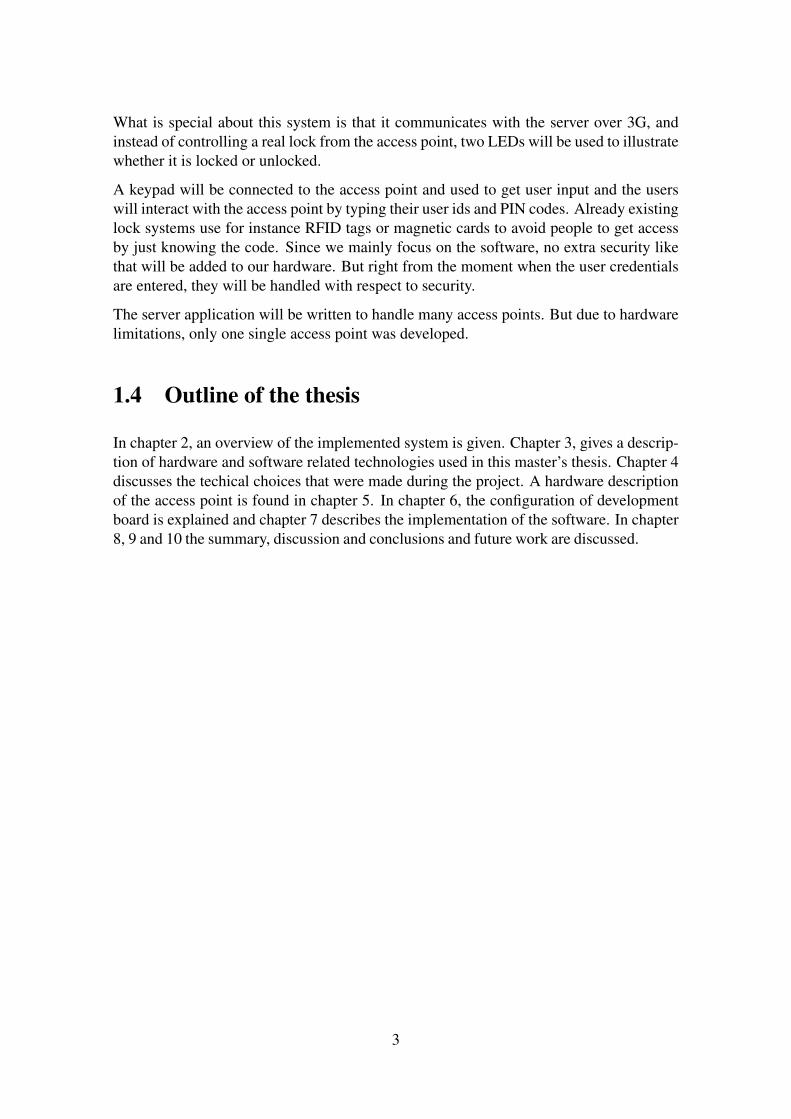
This section gives an overview of how the different parts in the system work together.The lock system consists of a server and a large number of access points, which is illus-trated in figure 2.1. Each access point talks to the server over the Internet to exchangeinformation.
Figure 2.1: An overview of the system.
2.1 Access Point
The implemented access point (AP) is a device that illustrates the functionality of anelectronic lock. An access point is needed at each location, e.g. a door that will beincluded in and controlled by the lock system. The overall functionality of the accesspoint is to collect ids and pin codes from users, ask the server if that user has access tothat specific location and if so let the user in.
4
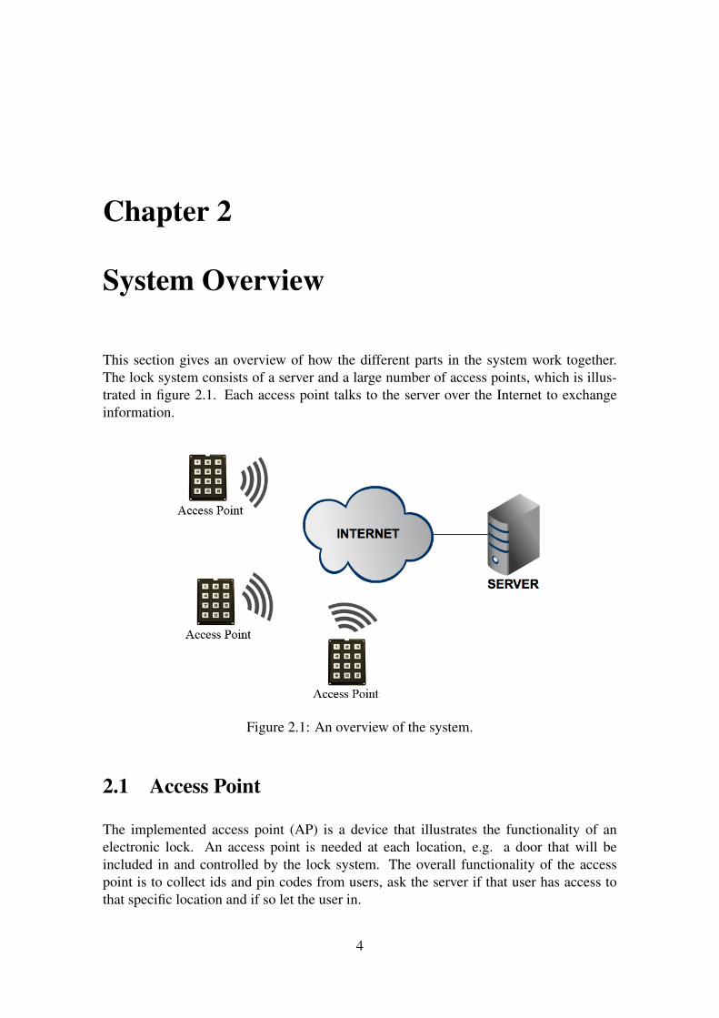
The AP, illustrated in figure 2.2, is based on a development board called BeagleBoard. Thereasons why that board is used are explained in section 4.1. The access point is equippedwith a 3G Broadband module to be able to connect to the Internet and talk to the locksystem server. The module is connected to the access point via one of the BeagleBoard’sUSB ports. In addition to the module, an external keypad is used to get input from theusers. In section 5.2, an explanation of the keypad construction is given.
The functionality of the access point is implemented in a program written in C. The pro-gram handles everything from establishing an Internet connection to recognize individualkey presses on the keypad. The implementation of this program is explained in sec-tion 7.2.
Figure 2.2: The access point that was developed.
2.2 Server
In the system a centralized server is used to handle the connections from all access points.The server controls the accesses of the users and based on their permissions, it accepts orrejects the unlock requests that are sent by the access points. For platform independency,this server application is written in Java and equipped with a graphical user interface toeasily manage the system. Each individual access point is managed from the server andits configuration is stored on the server.
5

Since new firmware is released to the 3G Broadband modules, the system remotely han-dles these updates. When an update is released, it is manually added and controlled fromthe graphical user interface. If the server discovers that an access point needs a firmwareupdate, that access point is informed about it and at what time the update will run. At thattime, the file including the update is distributed from the server.
In section 7.3, the implementation of the server application is explained.
6
Chapter 3
Technical Description
This chapter gives a description of different technologies that have been used in thisproject. Sections from this chapter is recommended to be read when they are referencedfrom other chapters in this report.
3.1 Hardware Related
3.1.1 Matrix Keypad
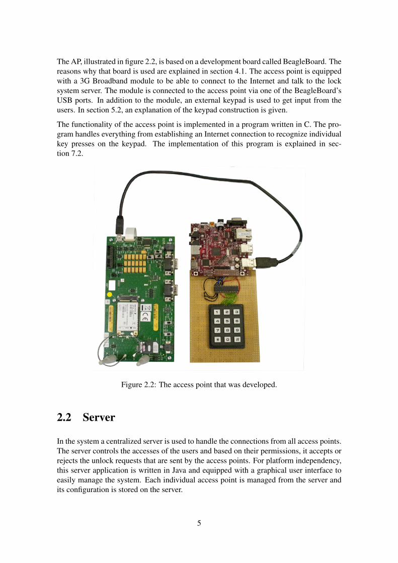
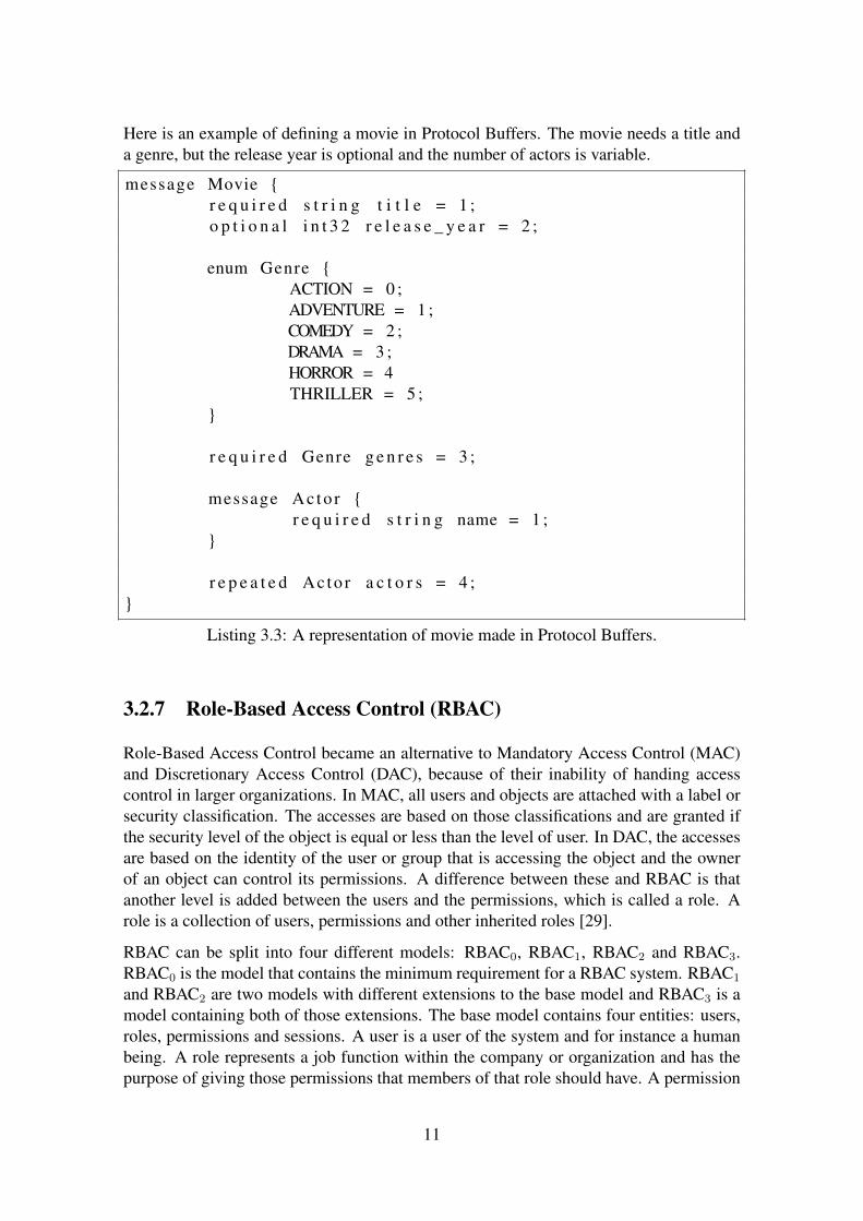
Matrix keypads are used in systems for human interaction. The architecture of a matrixkeypad is very simple and it is easy to use together with a microcontroller. The buttonsare arranged in a matrix, which can be seen in the figure below. The only components arethe buttons that are connected together in rows and columns [11].
Figure 3.1: A schematic of a keypad. (Figure from [11])
7
Since the keypad only contains buttons, which are simple switches, the direction of thesignals does not matter. Either the columns can be connected as output and the rowsas input to the I/O signals on the processor or vice versa. Suppose rows are inputs andcolumns are outputs: when a button is pressed, the column pin of the button has the samesignal value, thus ’0’ or ’1’, as its row pin. For instance, if SW1 in figure 3.1 is pressed,then Col1 has the same signal value as Row1. The value of a column pin is undefined ifno button is pressed within that column. Therefore pull-up (or pull-down) resistors areusually used on the output pins to get a value in those situations.
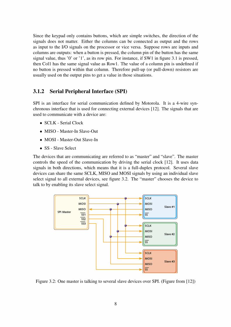
3.1.2 Serial Peripheral Interface (SPI)
SPI is an interface for serial communication defined by Motorola. It is a 4-wire syn-chronous interface that is used for connecting external devices [12]. The signals that areused to communicate with a device are:
• SCLK - Serial Clock
• MISO - Master-In Slave-Out
• MOSI - Master-Out Slave-In
• SS - Slave Select
The devices that are communicating are referred to as “master” and “slave”. The mastercontrols the speed of the communication by driving the serial clock [12]. It uses datasignals in both directions, which means that it is a full-duplex protocol. Several slavedevices can share the same SCLK, MISO and MOSI signals by using an individual slaveselect signal to all external devices, see figure 3.2. The “master” chooses the device totalk to by enabling its slave select signal.
Figure 3.2: One master is talking to several slave devices over SPI. (Figure from [12])
8
3.2 Software Related
3.2.1 AT Commands
The AT commands were first used in modems developed by a company called Hayes in1977. Earlier modems had used two different channels: one for sending and receivingdata and another channel for sending control commands to the modem. However, thismodem only used one channel for both data and control commands. To distinguish be-tween commands, each command sent to the control channel started with the charactersAT, which stands for attention. Because of these two characters, this set of commandsbecame known as AT commands. Other modem manufacturers started to use this set ofcommands because of simplicity [13].
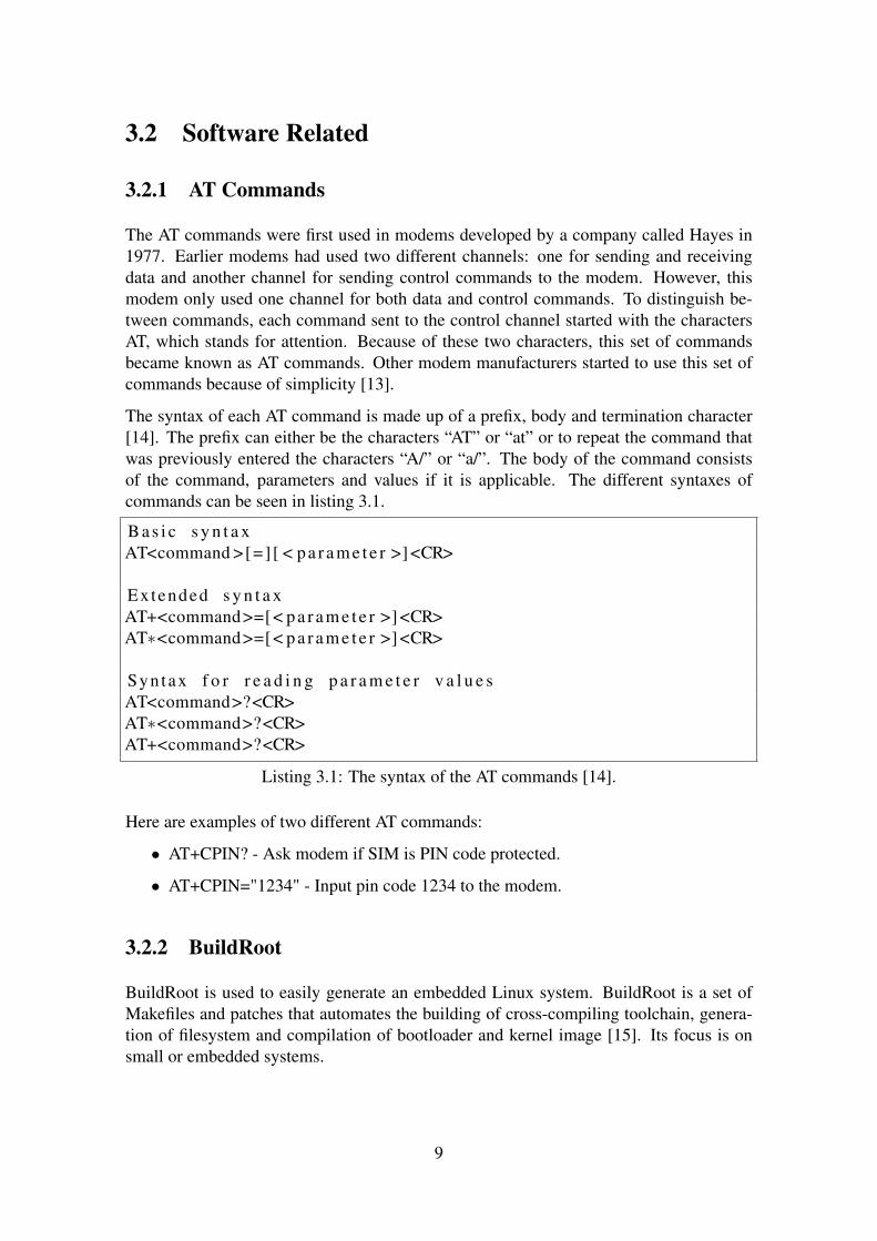
The syntax of each AT command is made up of a prefix, body and termination character[14]. The prefix can either be the characters “AT” or “at” or to repeat the command thatwas previously entered the characters “A/” or “a/”. The body of the command consistsof the command, parameters and values if it is applicable. The different syntaxes ofcommands can be seen in listing 3.1.
B a s i c s y n t a xAT<command >[=] [ < p a r a m e t e r >] <CR>
Extended s y n t a xAT+<command>=[< p a r a m e t e r >] <CR>AT∗<command>=[< p a r a m e t e r >] <CR>
Syntax f o r r e a d i n g p a r a m e t e r v a l u e sAT<command>?<CR>AT∗<command>?<CR>AT+<command>?<CR>
Listing 3.1: The syntax of the AT commands [14].
Here are examples of two different AT commands:
• AT+CPIN? - Ask modem if SIM is PIN code protected.
• AT+CPIN="1234" - Input pin code 1234 to the modem.
3.2.2 BuildRoot
BuildRoot is used to easily generate an embedded Linux system. BuildRoot is a set ofMakefiles and patches that automates the building of cross-compiling toolchain, genera-tion of filesystem and compilation of bootloader and kernel image [15]. Its focus is onsmall or embedded systems.
9
3.2.3 Cross-Compiling
In the compiling process, the terms host and target are used to differentiate between wherethe program is compiled and where the program will be executed, respectively. The com-piler is called native if the host and the target are the same, but it is called a cross-compilerif the host is different from the target machine. Cross-compilation is needed when the tar-get machine cannot run its own compiler, for example if it lacks resources like CPU orRAM capacity [16]. A cross-compiler is also needed to get Linux to run on a new hard-ware platform.
3.2.4 Model-View-Controller (MVC)
The design pattern Model-View-Controller is often used when graphical user interfacesare built. The design pattern consists of three different objects: model, view and con-troller. The model implements the functionality of the application, the view is the vi-sual feedback and the controller takes care of the user input. By following MVC, thecode is better structured, which increases flexibility and the ability to reuse the code [17].Separating the functionality of the program from the user interaction makes it easier tocreate several different views to the same program or use the same view in another pro-gram.
3.2.5 NMEA 0183
The standard NMEA 0183 is a definition of a communication protocol between marineinstrumentation. The data is transmitted in so-called sentences, which are sent betweentalkers and listeners [18]. The format of a sentence can be seen in listing 3.2 below.Each sentence starts with a ’$’ character followed by two characters representing thedevice’s type; for instance “GP” for a GPS receiver. The next three characters specifiesthe sentence identifier. The sentence ends with a number of data fields separated bycommas, a checksum and carriage return/line feed.
$ t t s s s , d1 , d2 , . . . . < CR><LF>
Listing 3.2: The structure of an NMEA 0183 sentence.
3.2.6 Protocol Buffers
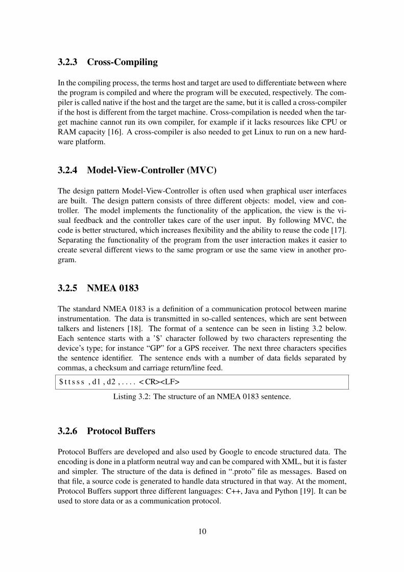
Protocol Buffers are developed and also used by Google to encode structured data. Theencoding is done in a platform neutral way and can be compared with XML, but it is fasterand simpler. The structure of the data is defined in “.proto” file as messages. Based onthat file, a source code is generated to handle data structured in that way. At the moment,Protocol Buffers support three different languages: C++, Java and Python [19]. It can beused to store data or as a communication protocol.
10
Here is an example of defining a movie in Protocol Buffers. The movie needs a title anda genre, but the release year is optional and the number of actors is variable.
message Movie {r e q u i r e d s t r i n g t i t l e = 1 ;o p t i o n a l i n t 3 2 r e l e a s e _ y e a r = 2 ;
enum Genre {ACTION = 0 ;ADVENTURE = 1 ;COMEDY = 2 ;DRAMA = 3 ;HORROR = 4THRILLER = 5 ;
}
r e q u i r e d Genre g e n r e s = 3 ;
message Ac to r {r e q u i r e d s t r i n g name = 1 ;
}
r e p e a t e d Ac to r a c t o r s = 4 ;}
Listing 3.3: A representation of movie made in Protocol Buffers.
3.2.7 Role-Based Access Control (RBAC)
Role-Based Access Control became an alternative to Mandatory Access Control (MAC)and Discretionary Access Control (DAC), because of their inability of handing accesscontrol in larger organizations. In MAC, all users and objects are attached with a label orsecurity classification. The accesses are based on those classifications and are granted ifthe security level of the object is equal or less than the level of user. In DAC, the accessesare based on the identity of the user or group that is accessing the object and the ownerof an object can control its permissions. A difference between these and RBAC is thatanother level is added between the users and the permissions, which is called a role. Arole is a collection of users, permissions and other inherited roles [29].
RBAC can be split into four different models: RBAC0, RBAC1, RBAC2 and RBAC3.RBAC0 is the model that contains the minimum requirement for a RBAC system. RBAC1
and RBAC2 are two models with different extensions to the base model and RBAC3 is amodel containing both of those extensions. The base model contains four entities: users,roles, permissions and sessions. A user is a user of the system and for instance a humanbeing. A role represents a job function within the company or organization and has thepurpose of giving those permissions that members of that role should have. A permission
11
is the same as granted access to an object. Sessions are used to control the permission leveland to just activate those roles that are needed for a specific task. The second model, calledRBAC1, introduces role inheritance into the system, which allows creation of hierarchiesof permissions. By letting roles inherit other roles, more powerful roles can be built uponless powerful roles. The next model, called RBAC2, defines constraints [30]. By havingconstraints in the system, roles can for instance be specified to be mutually exclusive,which means that a user can only be assigned one of those roles.
An advantage with using RBAC compared to other access controls is that permissions thatare assigned to a role tend to be more stable than permissions that are assigned directly tousers [30]. Users’ permissions need to be changed more often due to job function changesetc.
3.2.8 Sysfs
Sysfs is a filesystem and provides a way to manipulate kernel objects from user-space.Users and applications can easily access and control the kernel-space data structures,since the information is strictly organized and most often formatted in ASCII. In theLinux kernel, the kernel objects are represented as directories, object attributes as regu-lar files and the relation between objects with symbolic links. Sysfs is mounted on thedirectory /sys. Under this directory a number of subdirectories are created to representthe different subsystems that are registered with sysfs. These directories are block, bus,class, device, firmware, module and power. The block directory contains all devices thatare block devices that have been discovered. The bus directory contains a directory foreach different type of physical bus available in the system and supported by the kernel. Adirectory for every device class registered with the kernel is added to the class directory.In the device directory, a subdirectory is added for each device that has been discoveredon any bus registered with the kernel. Platform-specific code, like x86 BIOS, can be ma-nipulated or viewed through the interface in the firmware directory. All kernel modulesare added as a directory into the module directory. The last directory, called power, isan interface for controlling states of processes and controlling the method that should beused by the system to suspend to disk [20].
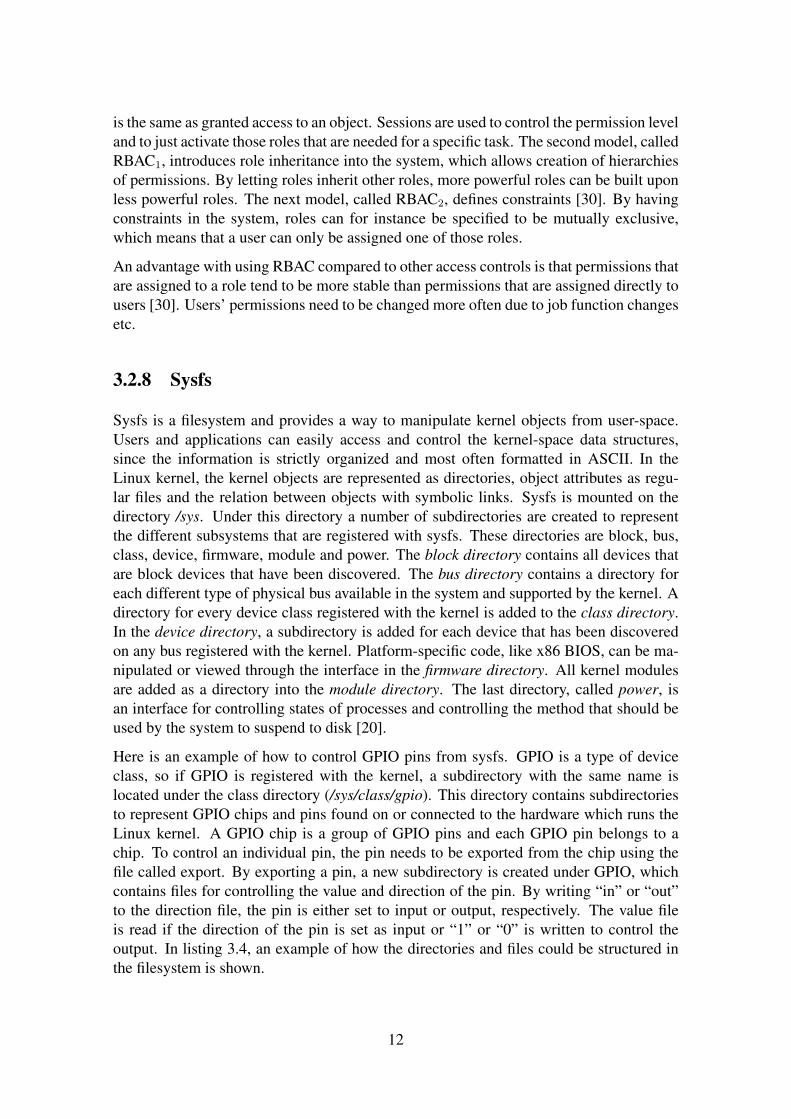
Here is an example of how to control GPIO pins from sysfs. GPIO is a type of deviceclass, so if GPIO is registered with the kernel, a subdirectory with the same name islocated under the class directory (/sys/class/gpio). This directory contains subdirectoriesto represent GPIO chips and pins found on or connected to the hardware which runs theLinux kernel. A GPIO chip is a group of GPIO pins and each GPIO pin belongs to achip. To control an individual pin, the pin needs to be exported from the chip using thefile called export. By exporting a pin, a new subdirectory is created under GPIO, whichcontains files for controlling the value and direction of the pin. By writing “in” or “out”to the direction file, the pin is either set to input or output, respectively. The value fileis read if the direction of the pin is set as input or “1” or “0” is written to control theoutput. In listing 3.4, an example of how the directories and files could be structured inthe filesystem is shown.
12
/ s y s / c l a s s / gp ioe x p o r tgp io243
d e v i c ed i r e c t i o npowersubsys t emu e v e n tv a l u e
g p i o c h i p 2 4 0based e v i c el a b e lngp iopowersubsys t emu e v e n t
u n e x p o r t
Listing 3.4: Gpio pin 243 is exported and controlled through sysfs.
13

Chapter 4
Technical Choices
4.1 Development Board
Right from the start, we decided that the access point will be based on a developmentboard that runs a Linux kernel. The development board that we used is BeagleBoard-xMRev C. Using a development board based on an ARM processor is preferable because itis cheap and well supported by the Linux kernel. The reason for using the BeagleBoard isfirst of all its support for SPI and USB. Secondly, its good specifications: 1 GHz processorand 512 MB of RAM. Thirdly, many others use it and good forums exist. Yet anotheradvantage is that it has an Ethernet port, which is great to have during the developmentprocess. The type of the BeagleBoard used is shown in figure 4.1.
Figure 4.1: BeagleBoard-xM Rev. C.
4.2 Handling Users
The lock system that is developed is designed to handle a large number of access pointsand a lot of users. To properly assign access rights to the user, it is important that the
14
management is made easy. Daradimos et al. [7] have created a system handling usersand access points, but it does not support a way of grouping users and grouping accesspoints and therefore it is not well suited for larger systems. However, their rules are basedon weekly access rights and is well suited for our system. Weekly access rights meanthat the rules are assigned what days and times users and access points should be activeduring a week; which are repeated on a weekly basis. Together with the weekly accessrights, the lock system is based on Role-Based Access Control (RBAC); see section 3.2.7.Popa et al. [8] suggest an access control system based on smart cards which uses RBACfor access control. In RBAC, roles are created based on job functions or tasks performedwithin a company or organization. That is a general way and can therefore be adapted tobasically all places where this lock system can be used.
4.3 Programming Languages
The program for the access point is written in C/C++. The combination of the languagesis used because Protocol Buffers generate C++ code, but the rest of the code is written inC. By using C/C++, the development of the program for the access point could start on aLinux machine before the development board was received.
The server program is written in Java to be able to move the program between differentoperating system. From the beginning it was not known on what operating system theapplication would run and therefore using Java made the program platform independent.In addition, it is easy to create graphical user interfaces and we know how to write Javaprograms. Using a database together with a Java program is also trivial and Java is one ofthe languages that Protocol Buffers support.
4.4 Communication Between Server and Access Points
The data exchanged between the server and the access points is structured in ProtocolBuffer messages; see section 3.2.6. Coming up with a new way of exchanging differenttypes of data takes time, therefore it is better to use a protocol that is tested and used byothers. Protocol Buffers is used because it is well documented, it is simple to use andit works with both Java and C++ [19]. An alternative can be Apache Thrift [21], origi-nally developed by Facebook, which is similar to Google’s Protocol Buffers. However,it is not well documented and has extra functionality that is not needed in this master’sthesis.
There are also other data serialization formats like XML and JSON. Protocol Buffershowever serializes structured data up to 100 times faster than XML [19] and neither XMLnor JSON have elements of raw byte data.
15
4.5 SSH vs IPSec
To prevent PIN codes from being eavesdropped, all data sent within the system is en-crypted. The encryption can either be embedded into the programs or existing third partyimplementations like SSH and IPsec can be used in combination with these programs.Implementing the encryption in the programs opens up for adding extra bugs and alsothat the encryption is not secure enough. Therefore, it is better to use existing SSH orIPsec implementations that are well established and tested. The advantage of using IPsecbetween the server and all access point is that it is a part of the operating system, whichmeans that once it is configured all traffic will automatically be encrypted without con-sidering it in the programs. However, the configuration of IPsec is harder than settingup an SSH tunnel. Since the access points are only talking to the server over one singleport, it is enough to set up one tunnel from each access point to the server to get all dataencrypted. Additionally, adding SSH to the Linux installation on the development boardis easy; just enabling it in the compilation. Therefore, we decided that the lock systemshould use SSH tunnels to encrypt the traffic.
4.6 Keypad Construction
The keypad is constructed to get input from the user. It is connected to the BeagleBoardvia a SPI to GPIO expander circuit. An alternative way is to use a USB keypad, whichis easily supported by Linux. But a USB keypad cannot be used if the extension to thismaster thesis should be possible. The extension is to port the program written for theaccess point to the module and to let it execute directly on its processor. As a result, theBeagleBoard is not needed, but just the 3G module with a keypad connected to it. In thatcase, the keypad is preferably connected to the GPIO pins on the module. Unfortunately,the number of available GPIO pins on the module is limited and not enough to connect akeypad. An alternative is to use a SPI to GPIO expander to get more available GPIO pins.The SPI to GPIO expander circuit used is MCP23S17. It supports 1.8 Volts, which is thevoltage of the pins of both the BeagleBoard and the 3G Broadband module, and there isalso a driver supporting the circuit in Linux.
16
Chapter 5
Hardware
This chapter gives a description of the hardware of the access point. In section 1, the 3GBroadband module used is described. Section 2 gives a detailed description of how thekeypad is connected to the development board.
5.1 Ericsson’s 3G Broadband Module
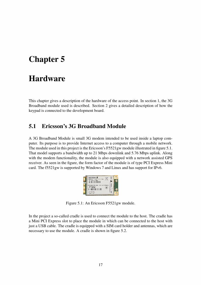
A 3G Broadband Module is small 3G modem intended to be used inside a laptop com-puter. Its purpose is to provide Internet access to a computer through a mobile network.The module used in this project is the Ericsson’s F5521gw module illustrated in figure 5.1.That model supports a bandwidth up to 21 Mbps downlink and 5.76 Mbps uplink. Alongwith the modem functionality, the module is also equipped with a network assisted GPSreceiver. As seen in the figure, the form factor of the module is of type PCI Express Minicard. The f5521gw is supported by Windows 7 and Linux and has support for IPv6.
Figure 5.1: An Ericsson F5521gw module.
In the project a so-called cradle is used to connect the module to the host. The cradle hasa Mini PCI Express slot to place the module in which can be connected to the host withjust a USB cable. The cradle is equipped with a SIM card holder and antennas, which arenecessary to use the module. A cradle is shown in figure 5.2.
17

Figure 5.2: A cradle that the 3G Broadband module is placed in.
5.1.1 AT Commands
The module is managed by sending AT commands from the host. See section 3.2.1 for amore detailed description of AT commands. The AT commands are sent to the module toone of its virtual serial ports that are created when the module is connected. The moduleshandle a large set of different AT commands which can change all of its settings includingto enable it when it is about to be used.
The AT commands used in this master’s thesis are only a subset of those that are available.The AT commands that are needed are used to turn on the module, input PIN code to theSIM card, establish an Internet connection, read GPS coordinates etc. A complete list ofall AT commands and their functionality is given in Appendix A.
5.1.2 Firmware Updates
Firmware updates for Ericsson’s 3G Broadband modules are released to correct bugs andimprove the functionality of the modules. The updates are developed by Ericsson, but areusually released together with updates from the laptop manufacturer that the module isused together with. The updates are installed by running the updater on the host, whichthe module is connected to. The installation of the update takes about 5 minutes anddirectly after its completion the module is ready to be used again.
18

5.2 Keypad Connection
A keypad is used to read input from the users and it is connected to the BeagleBoard’sextension connector. A schematic diagram over the connected components is illustratedin figure 5.3.
Figure 5.3: Connection of keypad to the BeagleBoard through a SPI to GPIO expander.
The component marked with ’1’ in the schematic is a connector that enables a plug inof the BeagleBoard’s extension connector. The extension connector is a 28-pin connec-tor used to externally connect peripherals to add more functionality to the board. In theconnector, I/O pins and different communication interfaces, like SPI and I2C, are avail-able; but also pins connected to ground, 1.8 and 5.0 volts. All pins that are connected tocommunication interfaces or I/O use 1.8 volts [22].
The circuit, called MCP23S17, marked with ’2’ connects the keypad to the BeagleBoard.It is a SPI to GPIO expander, which means that the BeagleBoard is equipped with 16extra GPIO pins by just talking to the circuit through SPI. Several similar I/O expanders
19
are available, but this circuit is used because it works with 1.8 volts and it is available ina DIP package. The pins on the I/O expander circuit marked with A0, A1 and A2 areaddress pins. Up to eight MCP23S17 circuits can be used on the same SPI bus, with thesame chip select signal, and with help of these signals, the hardware address of the circuitis specified [23]. Only one circuit is needed and the address of that one is set to 0x0 (allA-pins connected to ground). See section 6.1.1 to see how the address is configured inthe Linux kernel.
The keypad, marked with ’3’, is connected with seven signals to the MCP23S17 circuit.Four of the signals (ROW1, ROW2, ROW3 and ROW4), routed to the rows of the keypad,are connected as output pins from the expander circuit. The other three signals (COL1,COL2 and COL3), routed to the columns of the keypad, are connected as input to thecircuit.
20
Chapter 6
Configuring the Development Board
This chapter describes how to configure and build a customized Linux kernel for BeagleBoard-xM. The kernel is patched to support SPI and the MCP23S17 circuit. A description isalso given for how the SD card is prepared before it can be used together with the Bea-gleBoard.
6.1 Building a Customized Linux Kernel
Building a Linux kernel is not always needed. Pre-built kernels are available on the Inter-net and there are also webpages that can generate kernels on request. The need of buildinga Linux kernel arises when it has to be customized for a special purpose or for a new hard-ware. BeagleBoard is a type of development board which is commonly used, so there isno problem getting a kernel to work with it. However, using a pre-built kernel does notenable all functionality that is available on the board which is the reason for building acustomized kernel.
Due to hardware limitations of the BeagleBoard, the new kernel cannot be compiled onthe board itself, but has to be cross-compiled (see section 3.2.3) with a cross-compilationtoolchain. There are different ways of cross-compiling a kernel. One is to download apre-built cross-compilation toolchain and use that for compiling the kernel. But a moresuitable way, for this project, is to use BuildRoot, see section 3.2.2 for more informa-tion. In the configuration of BuildRoot, an external cross-compiling toolchain1, Linuxkernel 3.1.4 and a root filesystem is enabled. The BeagleBoard is already shipped with abootloader and therefore BuildRoot does not need to compile another one. To customizethe kernel, a kernel patch and a custom kernel configuration file are also enabled in theBuildRoot configuration.
1The cross-compilation toolchain that BuildRoot compiles uses uClibc, which is a reduced C librarycompared to GNU C Library. The tool for updating the firmware of the 3G Broadband Module is writtenfor the latter and does not support uClibc. Therefore BuildRoot is configured to use an external toolchain.
21
6.1.1 Kernel Patch
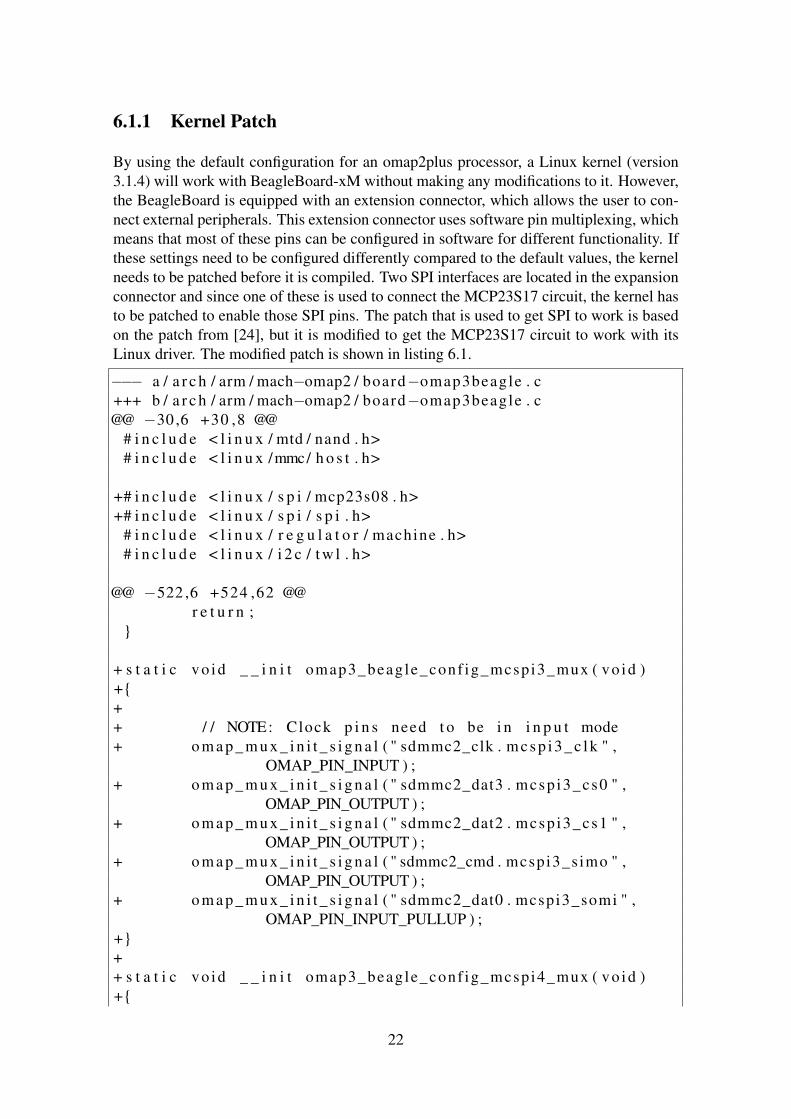
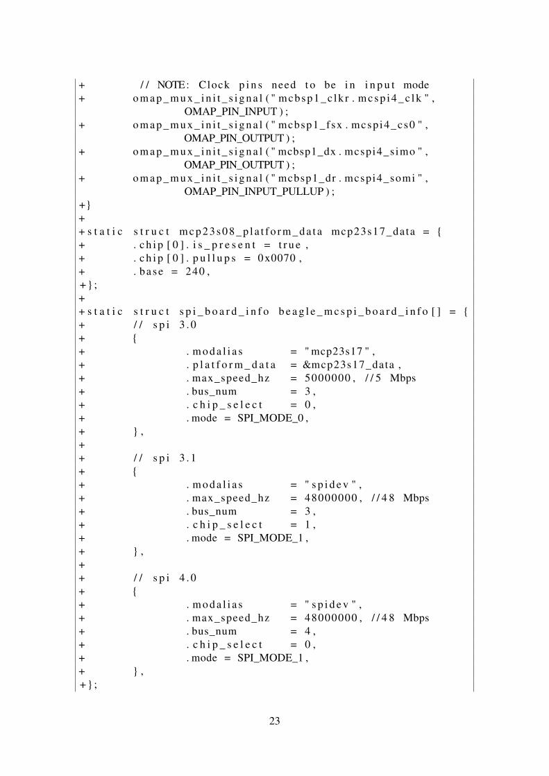
By using the default configuration for an omap2plus processor, a Linux kernel (version3.1.4) will work with BeagleBoard-xM without making any modifications to it. However,the BeagleBoard is equipped with an extension connector, which allows the user to con-nect external peripherals. This extension connector uses software pin multiplexing, whichmeans that most of these pins can be configured in software for different functionality. Ifthese settings need to be configured differently compared to the default values, the kernelneeds to be patched before it is compiled. Two SPI interfaces are located in the expansionconnector and since one of these is used to connect the MCP23S17 circuit, the kernel hasto be patched to enable those SPI pins. The patch that is used to get SPI to work is basedon the patch from [24], but it is modified to get the MCP23S17 circuit to work with itsLinux driver. The modified patch is shown in listing 6.1.
−−− a / a r c h / arm / mach−omap2 / board−omap3beagle . c+++ b / a r c h / arm / mach−omap2 / board−omap3beagle . c@@ −30 ,6 +30 ,8 @@
# i n c l u d e < l i n u x / mtd / nand . h># i n c l u d e < l i n u x /mmc/ h o s t . h>
+# i n c l u d e < l i n u x / s p i / mcp23s08 . h>+# i n c l u d e < l i n u x / s p i / s p i . h>
# i n c l u d e < l i n u x / r e g u l a t o r / machine . h># i n c l u d e < l i n u x / i 2 c / t w l . h>
@@ −522 ,6 +524 ,62 @@r e t u r n ;
}
+ s t a t i c vo id _ _ i n i t omap3_beagle_conf ig_mcspi3_mux ( vo id )+{++ / / NOTE: Clock p i n s need t o be i n i n p u t mode+ o m a p _ m u x _ i n i t _ s i g n a l ( " sdmmc2_clk . m c s p i 3 _ c l k " ,
OMAP_PIN_INPUT ) ;+ o m a p _ m u x _ i n i t _ s i g n a l ( " sdmmc2_dat3 . mcsp i3_cs0 " ,
OMAP_PIN_OUTPUT ) ;+ o m a p _ m u x _ i n i t _ s i g n a l ( " sdmmc2_dat2 . mcsp i3_cs1 " ,
OMAP_PIN_OUTPUT ) ;+ o m a p _ m u x _ i n i t _ s i g n a l ( " sdmmc2_cmd . mcspi3_simo " ,
OMAP_PIN_OUTPUT ) ;+ o m a p _ m u x _ i n i t _ s i g n a l ( " sdmmc2_dat0 . mcspi3_somi " ,
OMAP_PIN_INPUT_PULLUP ) ;+}++ s t a t i c vo id _ _ i n i t omap3_beagle_conf ig_mcspi4_mux ( vo id )+{
22
+ / / NOTE: Clock p i n s need t o be i n i n p u t mode+ o m a p _ m u x _ i n i t _ s i g n a l ( " mcbsp1_c lk r . m c s p i 4 _ c l k " ,
OMAP_PIN_INPUT ) ;+ o m a p _ m u x _ i n i t _ s i g n a l ( " mcbsp1_fsx . mcsp i4_cs0 " ,
OMAP_PIN_OUTPUT ) ;+ o m a p _ m u x _ i n i t _ s i g n a l ( " mcbsp1_dx . mcspi4_simo " ,
OMAP_PIN_OUTPUT ) ;+ o m a p _ m u x _ i n i t _ s i g n a l ( " mcbsp1_dr . mcspi4_somi " ,
OMAP_PIN_INPUT_PULLUP ) ;+}++ s t a t i c s t r u c t m c p 2 3 s 0 8 _ p l a t f o r m _ d a t a mcp23s17_data = {+ . c h i p [ 0 ] . i s _ p r e s e n t = t r u e ,+ . c h i p [ 0 ] . p u l l u p s = 0x0070 ,+ . ba se = 240 ,+} ;++ s t a t i c s t r u c t s p i _ b o a r d _ i n f o b e a g l e _ m c s p i _ b o a r d _ i n f o [ ] = {+ / / s p i 3 . 0+ {+ . m o d a l i a s = " mcp23s17 " ,+ . p l a t f o r m _ d a t a = &mcp23s17_data ,+ . max_speed_hz = 5000000 , / / 5 Mbps+ . bus_num = 3 ,+ . c h i p _ s e l e c t = 0 ,+ . mode = SPI_MODE_0 ,+ } ,++ / / s p i 3 . 1+ {+ . m o d a l i a s = " s p i d e v " ,+ . max_speed_hz = 48000000 , / / 4 8 Mbps+ . bus_num = 3 ,+ . c h i p _ s e l e c t = 1 ,+ . mode = SPI_MODE_1 ,+ } ,++ / / s p i 4 . 0+ {+ . m o d a l i a s = " s p i d e v " ,+ . max_speed_hz = 48000000 , / / 4 8 Mbps+ . bus_num = 4 ,+ . c h i p _ s e l e c t = 0 ,+ . mode = SPI_MODE_1 ,+ } ,+} ;
23

+s t a t i c vo id _ _ i n i t o m a p 3 _ b e a g l e _ i n i t ( vo id ){
omap3_mux_ini t ( board_mux , OMAP_PACKAGE_CBB ) ;@@ −534 ,6 +592 ,11 @@
ARRAY_SIZE( o m a p 3 _ b e a g l e _ d e v i c e s ) ) ;o m a p _ d i s p l a y _ i n i t (& b e a g l e _ d s s _ d a t a ) ;o m a p _ s e r i a l _ i n i t ( ) ;
++ omap3_beagle_conf ig_mcspi3_mux ( ) ;+ omap3_beagle_conf ig_mcspi4_mux ( ) ;+ s p i _ r e g i s t e r _ b o a r d _ i n f o ( b e a g l e _ m c s p i _ b o a r d _ i n f o ,+ ARRAY_SIZE( b e a g l e _ m c s p i _ b o a r d _ i n f o ) ) ;
omap_mux_in i t_gp io ( 1 7 0 , OMAP_PIN_INPUT ) ;
Listing 6.1: Kernel Patch.
The patch contains functions and data structures to enable the SPI on the BeagleBoard.The two functions that are added are executed by the kernel to mux the pins to be usedas SPI interfaces. The structure called “beagle_mcspi_board_info” contains the settingsfor the SPI interfaces. Which can be seen in listing 6.1, SPI interface 3.0 is different frominterface 3.1 and 4.0. The 3.0 interface is modified to use the driver for mcp23s17 circuitinstead of spidev. That driver requires platform data about the circuit, which is given in thestructure called “mcp23s17_data”. By default, all chips in the data structure is disabled, soat the first row the MCP23S17 chip with address 0x0 is enabled, see the description of theaddresses in section 5.2. The pullup resistors that the MCP23S17 circuit is equipped withare enabled for three of the signals from the keypad. The output value from the keypad isundefined if no button is pressed, so pull-up resistors are required on the output pins fromthe keypad. The last row in the structure specifies the base of the circuit. The base tellsthe driver what number the first GPIO pin will be assigned in sysfs (see section 3.2.8).In this case, there are 16 GPIO pins available so the pins will be assigned the numbers240-255 and grouped together as a gpiochip in /sys/class/gpio.
6.1.2 Kernel Configuration
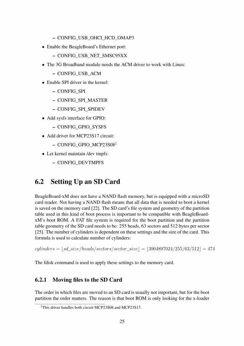
In the kernel source tree, there is a default configuration, called “omap2plus_defconfig”,that works with BeagleBoard-xM. However, this configuration does not enable everythingon the board that is needed and the drivers for the module and the MCP23S17 circuit arenot included. Here are those configs that are enabled in the kernel configuration:
• Enable the BeagleBoard’s USB ports:
– CONFIG_USB_EHCI_HCD
– CONFIG_USB_EHCI_HCD_OMAP
– CONFIG_USB_OHCI_HCD
24
– CONFIG_USB_OHCI_HCD_OMAP3
• Enable the BeagleBoard’s Ethernet port:
– CONFIG_USB_NET_SMSC95XX
• The 3G Broadband module needs the ACM driver to work with Linux:
– CONFIG_USB_ACM
• Enable SPI driver in the kernel:
– CONFIG_SPI
– CONFIG_SPI_MASTER
– CONFIG_SPI_SPIDEV
• Add sysfs interface for GPIO:
– CONFIG_GPIO_SYSFS
• Add driver for MCP23S17 circuit:
– CONFIG_GPIO_MCP23S082
• Let kernel maintain /dev tmpfs:
– CONFIG_DEVTMPFS
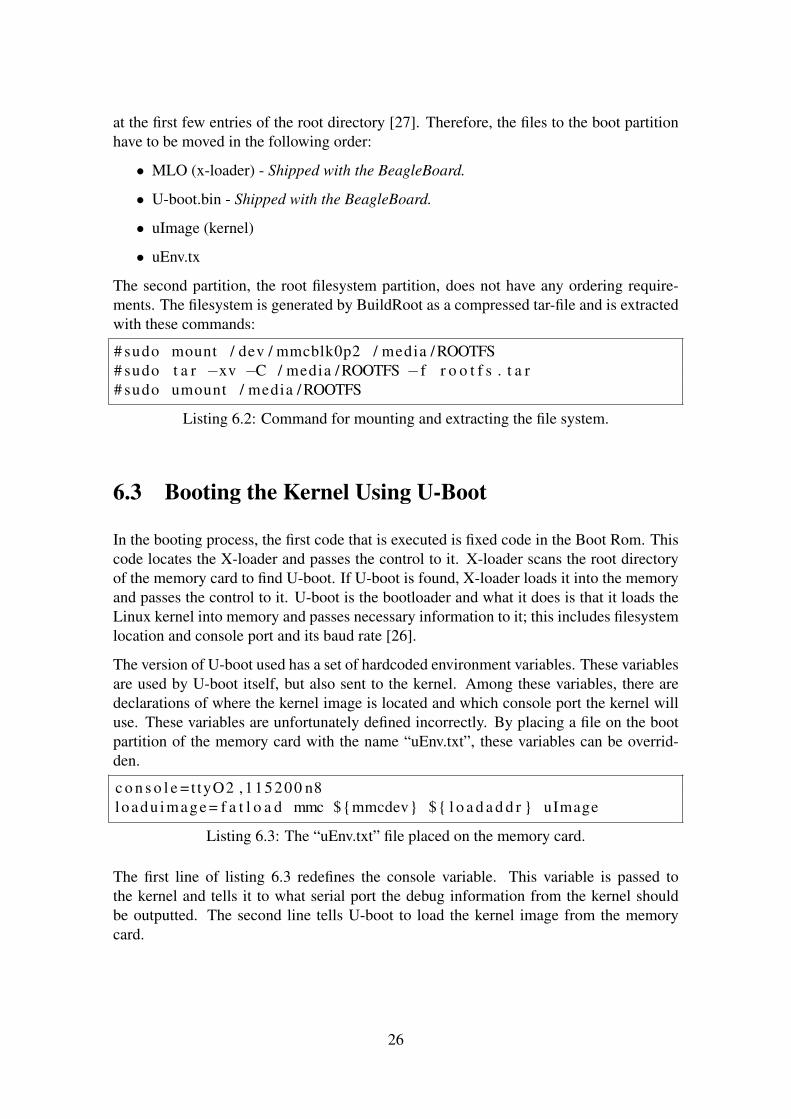
6.2 Setting Up an SD Card
BeagleBoard-xM does not have a NAND flash memory, but is equipped with a microSDcard reader. Not having a NAND flash means that all data that is needed to boot a kernelis saved on the memory card [22]. The SD card’s file system and geometry of the partitiontable used in this kind of boot process is important to be compatible with BeagleBoard-xM’s boot ROM. A FAT file system is required for the boot partition and the partitiontable geometry of the SD card needs to be: 255 heads, 63 sectors and 512 bytes per sector[25]. The number of cylinders is dependent on these settings and the size of the card. Thisformula is used to calculate number of cylinders:
cylinders = bsd_size/heads/sectors/sector_sizec = b3904897024/255/63/512c = 474
The fdisk command is used to apply these settings to the memory card.
6.2.1 Moving files to the SD Card
The order in which files are moved to an SD card is usually not important, but for the bootpartition the order matters. The reason is that boot ROM is only looking for the x-loader
2This driver handles both circuit MCP23S08 and MCP23S17.
25
at the first few entries of the root directory [27]. Therefore, the files to the boot partitionhave to be moved in the following order:
• MLO (x-loader) - Shipped with the BeagleBoard.
• U-boot.bin - Shipped with the BeagleBoard.
• uImage (kernel)
• uEnv.tx
The second partition, the root filesystem partition, does not have any ordering require-ments. The filesystem is generated by BuildRoot as a compressed tar-file and is extractedwith these commands:
# sudo mount / dev / mmcblk0p2 / media / ROOTFS# sudo t a r −xv −C / media / ROOTFS −f r o o t f s . t a r# sudo umount / media / ROOTFS
Listing 6.2: Command for mounting and extracting the file system.
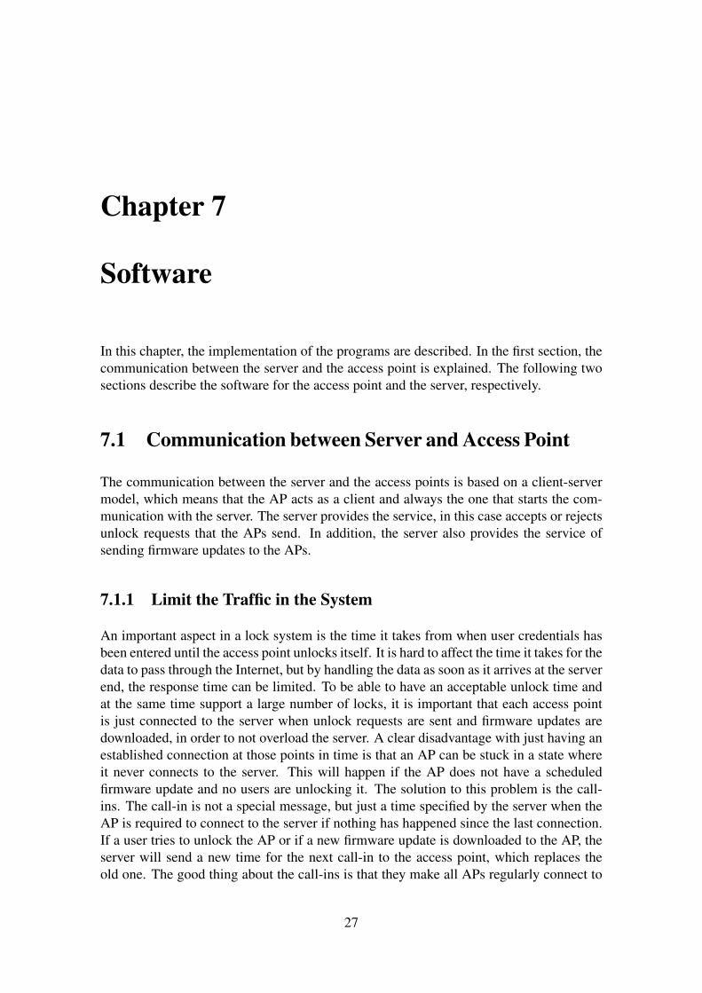
6.3 Booting the Kernel Using U-Boot
In the booting process, the first code that is executed is fixed code in the Boot Rom. Thiscode locates the X-loader and passes the control to it. X-loader scans the root directoryof the memory card to find U-boot. If U-boot is found, X-loader loads it into the memoryand passes the control to it. U-boot is the bootloader and what it does is that it loads theLinux kernel into memory and passes necessary information to it; this includes filesystemlocation and console port and its baud rate [26].
The version of U-boot used has a set of hardcoded environment variables. These variablesare used by U-boot itself, but also sent to the kernel. Among these variables, there aredeclarations of where the kernel image is located and which console port the kernel willuse. These variables are unfortunately defined incorrectly. By placing a file on the bootpartition of the memory card with the name “uEnv.txt”, these variables can be overrid-den.
c o n s o l e = t tyO2 ,115200 n8loadu image = f a t l o a d mmc ${mmcdev} ${ l o a d a d d r } uImage
Listing 6.3: The “uEnv.txt” file placed on the memory card.
The first line of listing 6.3 redefines the console variable. This variable is passed tothe kernel and tells it to what serial port the debug information from the kernel shouldbe outputted. The second line tells U-boot to load the kernel image from the memorycard.
26
Chapter 7
Software
In this chapter, the implementation of the programs are described. In the first section, thecommunication between the server and the access point is explained. The following twosections describe the software for the access point and the server, respectively.
7.1 Communication between Server and Access Point
The communication between the server and the access points is based on a client-servermodel, which means that the AP acts as a client and always the one that starts the com-munication with the server. The server provides the service, in this case accepts or rejectsunlock requests that the APs send. In addition, the server also provides the service ofsending firmware updates to the APs.
7.1.1 Limit the Traffic in the System
An important aspect in a lock system is the time it takes from when user credentials hasbeen entered until the access point unlocks itself. It is hard to affect the time it takes for thedata to pass through the Internet, but by handling the data as soon as it arrives at the serverend, the response time can be limited. To be able to have an acceptable unlock time andat the same time support a large number of locks, it is important that each access pointis just connected to the server when unlock requests are sent and firmware updates aredownloaded, in order to not overload the server. A clear disadvantage with just having anestablished connection at those points in time is that an AP can be stuck in a state whereit never connects to the server. This will happen if the AP does not have a scheduledfirmware update and no users are unlocking it. The solution to this problem is the call-ins. The call-in is not a special message, but just a time specified by the server when theAP is required to connect to the server if nothing has happened since the last connection.If a user tries to unlock the AP or if a new firmware update is downloaded to the AP, theserver will send a new time for the next call-in to the access point, which replaces theold one. The good thing about the call-ins is that they make all APs regularly connect to
27
the server, including the APs which are not often unlocked by users. By knowing that allAPs regularly connect allows the server to centrally store each access point’s settings andmake changes to them.
7.1.2 Protocol Buffers Messages
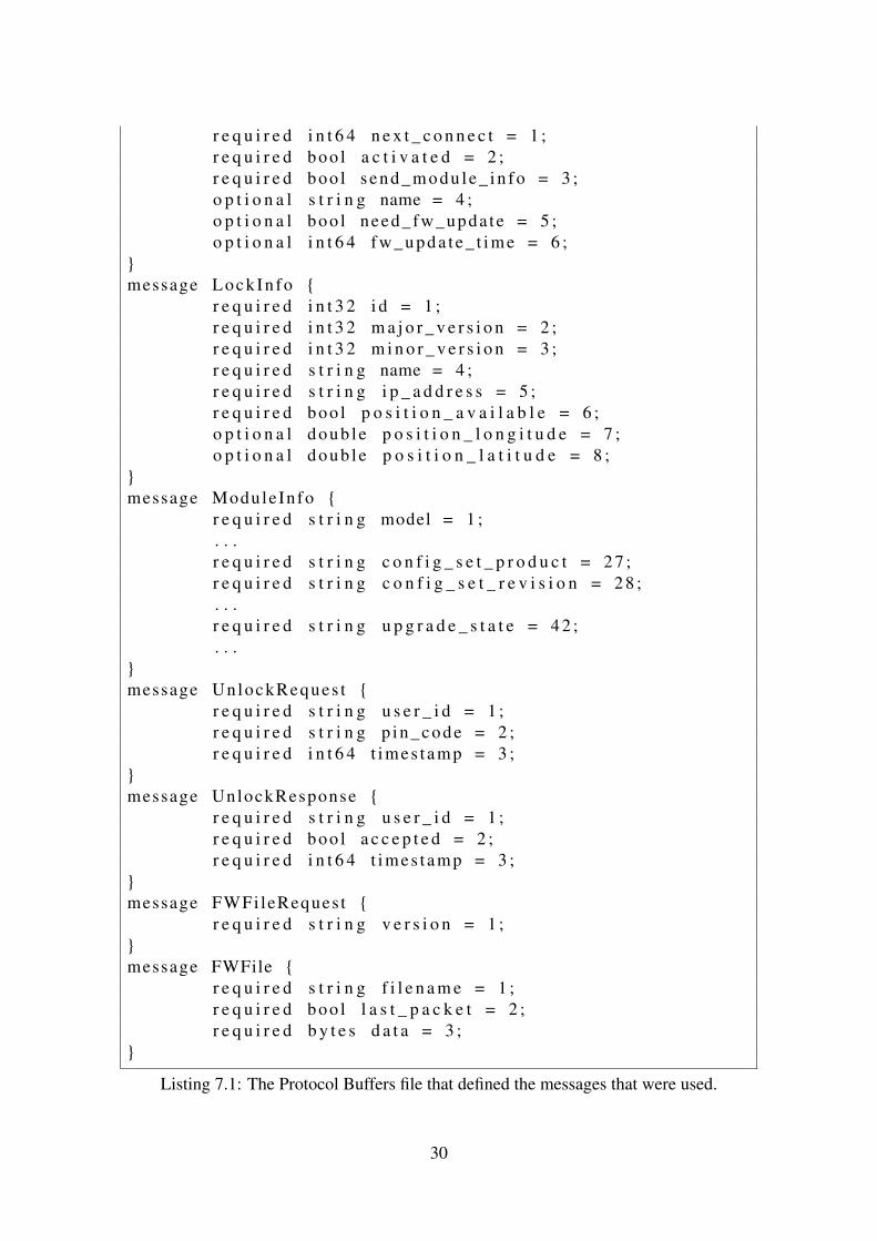
The data that is exchanged between the server and the access points is structured in Proto-col Buffers messages, see section 3.2.6 for more information. Using this flexible protocolmakes it easy to exchange information and at the same time make changes during thedevelopment phase if it is needed. The information to be exchanged is divided into sev-eral messages; one message is used for each stage in the communication. A messageis sent by first serializing it and then outputting it to the stream. At the destination, thedata received from the input stream is first stored into a buffer and then parsed back in amessage with help of Protocol Buffers’ function. That function needs to know what mes-sage it is parsing, because that cannot be distinguished from the data itself. Therefore, amessage is used as an envelope to carry the rest of the messages. That message is called“LockMessage” and consists of a message type and several different nested messages.The receiver always parses the received data in this message and by looking at the type,it knows whether an optional message is included or not. In listing 7.1, all messages usedin the communication are shown. Here follows an explanation of each message and whatit is used for:
• LockMessage - This message is sent every time data is sent between the serverand the access point. The functionality can be likened with an envelope, thus usedfor holding the messages that are sent. For the receiver to know what is includedinside this message, a type is always required. Depending on the type, one or zerooptional messages can be included. Some of the types do not need to add an optionalmessage; for example the type “DISCONNECT” which is used to inform the serverthat the access point is about to disconnect and no more information is needed.
• LockInfo - The access point uses this message when opening a new connection tothe server. This message has fields for specifying the lock id, name etc., which isused by the server to identify the access point.
• ServerInfo - This message is sent as a response to the “LockInfo” message. Itincludes some information about the server and also a “LockInfoUpdate” messageto the access point.
• LockInfoUpdate - This message includes updates to the AP. It specifies at whattime the lock is required to call-in next time, whether the lock is activated or inacti-vated, if the server needs new 3G module information and an option describing thename of the access point. There are also options that tell if firmware updates areavailable, and if so, when it will occur.
• ModuleInfo - This message is used to update the server about the 3G BroadbandModule that the access point is using. This information can be requested by theserver via the “LockInfoUpdate” message or sent by the AP after a firmware update.
28
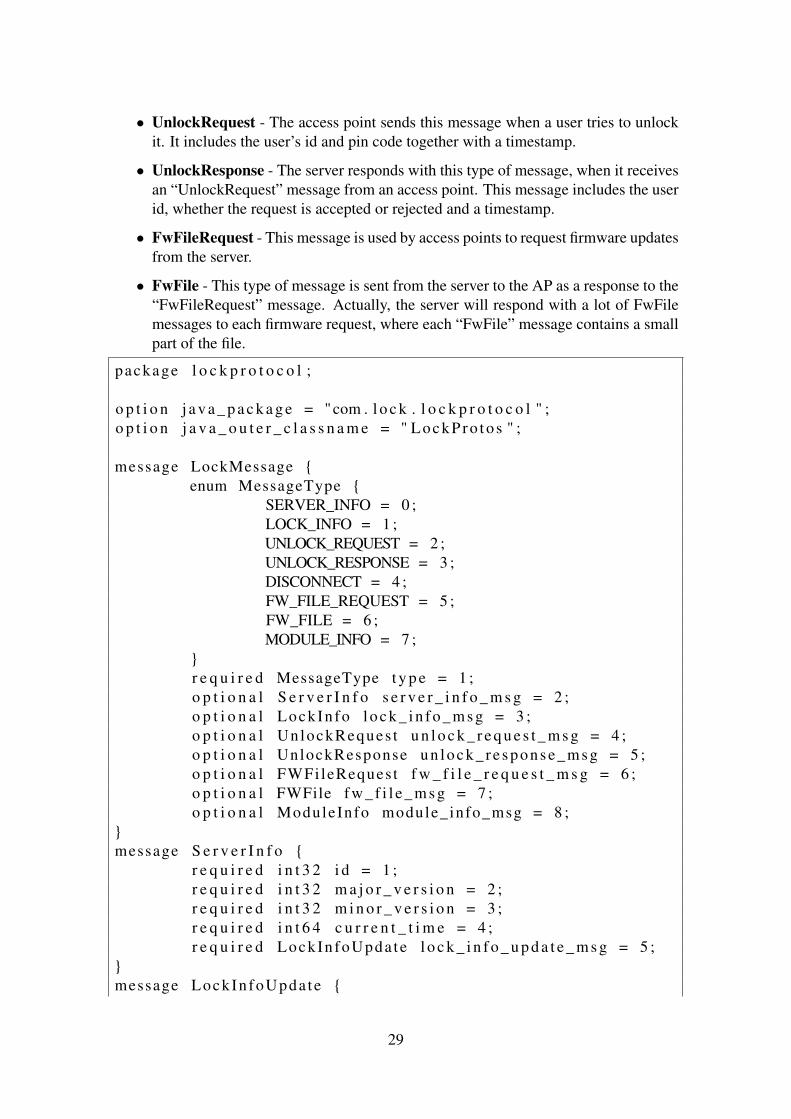
• UnlockRequest - The access point sends this message when a user tries to unlockit. It includes the user’s id and pin code together with a timestamp.
• UnlockResponse - The server responds with this type of message, when it receivesan “UnlockRequest” message from an access point. This message includes the userid, whether the request is accepted or rejected and a timestamp.
• FwFileRequest - This message is used by access points to request firmware updatesfrom the server.
• FwFile - This type of message is sent from the server to the AP as a response to the“FwFileRequest” message. Actually, the server will respond with a lot of FwFilemessages to each firmware request, where each “FwFile” message contains a smallpart of the file.
package l o c k p r o t o c o l ;
o p t i o n j a v a _ p a c k a g e = "com . l o c k . l o c k p r o t o c o l " ;o p t i o n j a v a _ o u t e r _ c l a s s n a m e = " L o c k P r o t o s " ;
message LockMessage {enum MessageType {
SERVER_INFO = 0 ;LOCK_INFO = 1 ;UNLOCK_REQUEST = 2 ;UNLOCK_RESPONSE = 3 ;DISCONNECT = 4 ;FW_FILE_REQUEST = 5 ;FW_FILE = 6 ;MODULE_INFO = 7 ;
}r e q u i r e d MessageType t y p e = 1 ;o p t i o n a l S e r v e r I n f o s e r v e r _ i n f o _ m s g = 2 ;o p t i o n a l LockIn fo l o c k _ i n f o _ m s g = 3 ;o p t i o n a l UnlockReques t u n l o c k _ r e q u e s t _ m s g = 4 ;o p t i o n a l UnlockResponse un lo c k_ re s po ns e _m sg = 5 ;o p t i o n a l FWFileReques t f w _ f i l e _ r e q u e s t _ m s g = 6 ;o p t i o n a l FWFile f w _ f i l e _ m s g = 7 ;o p t i o n a l ModuleInfo module_info_msg = 8 ;
}message S e r v e r I n f o {
r e q u i r e d i n t 3 2 i d = 1 ;r e q u i r e d i n t 3 2 m a j o r _ v e r s i o n = 2 ;r e q u i r e d i n t 3 2 m i n o r _ v e r s i o n = 3 ;r e q u i r e d i n t 6 4 c u r r e n t _ t i m e = 4 ;r e q u i r e d LockIn foUpda te l o c k _ i n f o _ u p d a t e _ m s g = 5 ;
}message LockIn foUpda te {
29
r e q u i r e d i n t 6 4 n e x t _ c o n n e c t = 1 ;r e q u i r e d boo l a c t i v a t e d = 2 ;r e q u i r e d boo l s e n d _ m o d u l e _ i n f o = 3 ;o p t i o n a l s t r i n g name = 4 ;o p t i o n a l boo l need_fw_upda te = 5 ;o p t i o n a l i n t 6 4 f w _ u p d a t e _ t i m e = 6 ;
}message LockIn fo {
r e q u i r e d i n t 3 2 i d = 1 ;r e q u i r e d i n t 3 2 m a j o r _ v e r s i o n = 2 ;r e q u i r e d i n t 3 2 m i n o r _ v e r s i o n = 3 ;r e q u i r e d s t r i n g name = 4 ;r e q u i r e d s t r i n g i p _ a d d r e s s = 5 ;r e q u i r e d boo l p o s i t i o n _ a v a i l a b l e = 6 ;o p t i o n a l d ou b l e p o s i t i o n _ l o n g i t u d e = 7 ;o p t i o n a l d ou b l e p o s i t i o n _ l a t i t u d e = 8 ;
}message ModuleInfo {
r e q u i r e d s t r i n g model = 1 ;. . .r e q u i r e d s t r i n g c o n f i g _ s e t _ p r o d u c t = 2 7 ;r e q u i r e d s t r i n g c o n f i g _ s e t _ r e v i s i o n = 2 8 ;. . .r e q u i r e d s t r i n g u p g r a d e _ s t a t e = 4 2 ;. . .
}message UnlockReques t {
r e q u i r e d s t r i n g u s e r _ i d = 1 ;r e q u i r e d s t r i n g p i n _ c o d e = 2 ;r e q u i r e d i n t 6 4 t imes t amp = 3 ;
}message UnlockResponse {
r e q u i r e d s t r i n g u s e r _ i d = 1 ;r e q u i r e d boo l a c c e p t e d = 2 ;r e q u i r e d i n t 6 4 t imes t amp = 3 ;
}message FWFileReques t {
r e q u i r e d s t r i n g v e r s i o n = 1 ;}message FWFile {
r e q u i r e d s t r i n g f i l e n a m e = 1 ;r e q u i r e d boo l l a s t _ p a c k e t = 2 ;r e q u i r e d b y t e s d a t a = 3 ;
}
Listing 7.1: The Protocol Buffers file that defined the messages that were used.
30

7.1.3 The Order of the Messages
As described above, the “LockMessage” is always sent between the server and the APsand can be considered as an “envelope” to the other messages. The messages describedhere are the messages included inside the “envelope”.
The access point starts the communication by sending the “LockInfo” message to theserver. This message contains enough information about the AP for the server to knowwhom it is talking to. Based on that information, the server makes the decision whetherto continue the communication or not. If the server accepts the connection, the serverresponds with a “ServerInfo” message to the AP. If the server is requesting 3G moduleinformation or if the firmware has been updated or access point restarted since the lastconnection, the AP now sends a “ModuleInfo” message to the server. The AP checks ifuser data is available and in that case sends an “UnlockRequest” message to the server.The server responds to the AP with an “UnlockResponse”, where the decision of therequest is included. If the server has indicated, in an earlier message, that a firmwareupdate is available and the time when this should happen is fulfilled, the access pointwill now send “FwFileRequest” to request the file from the server. The server sends thefile, which is divided into several “FwFile” messages. Regardless of what has been doneduring the connection, the AP will end the communication by sending a message of type“DISCONNECT”.
7.1.4 Sending Subsequent Messages
Protocol Buffers does not have the functionality to know when a message ends. Sincemessages are frequently sent between the server and the access points, situations whereseveral messages are stored in the same buffer at the same time occurs. In those situations,the functions for parsing the messages will parse all messages in the buffer as one messageand then report an error. In the suggested solution by [28] and in the way it is handled,the size of the upcoming message is first sent to the stream and then the message itself.This is illustrated in figure 7.1. At the receiving end, the size is first read and given as anargument to the Protocol Buffers functions to parse the message.
Figure 7.1: Illustration of a message and its size in a buffer.
31
7.1.5 Encrypted Communication
In a lock system like this, it is important that the communication is encrypted to preventsensitive information from being eavesdropped and unlock requests from being insertedinto communication. If information would leak or if unlock requests would be inserted,it can have devastating consequences and let unauthorized persons into rooms or buildingthat they usually do not have access to. To prevent this from happening all informationsent between the server and the access points is encrypted with SSH. The lock systemserver runs an SSH server and each access point sets up and pipes all traffic through anSSH tunnel. The server does not accept access points that do not encrypt the traffic.
7.1.6 Sending Firmware Updates
The firmware updates are sent from the server to the access points to be able to remotelyupdate each 3G Broadband Module. The file used to update the module is a rather bigfile, about 20 MB. Therefore it is required to split it up, because Protocol Buffers cannothandle messages that big. The message used to send each piece is the “FwFile” messageas described above. No messages are used to acknowledge each piece, because that wouldslow down the transfer. Instead the server sends all pieces directly after each other withoutwaiting for a response from the access point. TCP is used in the communication and sinceit guarantees data delivery, acknowledgements are not actually needed.
7.2 Access Point Software
This section describes how the program written for the access point is implemented. Theprogram reads user input from the keypad, sets up an Internet connection through the 3GBroadband module and encrypts the traffic over an SSH tunnel etc.
7.2.1 Program Flow
The functionality of the access point program is implemented in a while-loop. The pro-gram connects to the server if user data is available, if it is time for a call-in or a firmwareupdate is scheduled. A more detailed description of the program flow is given in fig-ure 7.2.
32

Figure 7.2: Flowchart explaining the program flow of the access point.
7.2.2 Communicating with 3G Broadband Module
When the module is connected to the development board, the ACM driver enabled in thecustomized kernel is loaded. Three different virtual serial ports, “ttyACM0”, “ttyACM1”and “ttyACM2”, are created under “/dev” in the file system. The interaction with themodule is done through AT commands, which are sent to those serial ports. To send theAT commands and receive results from the module, the ports are opened as regular files,commands are written and results are read as in usual Linux file I/O.
7.2.3 Connecting to the Internet
To connect to the Internet through the module, a subset of AT commands are sent inthe order explained in figure 7.3. Instead of giving the name of the AT commands, thefunctionality of them is explained. All AT commands are given in Appendix A.
33
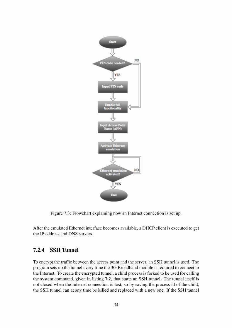
Figure 7.3: Flowchart explaining how an Internet connection is set up.
After the emulated Ethernet interface becomes available, a DHCP client is executed to getthe IP address and DNS servers.
7.2.4 SSH Tunnel
To encrypt the traffic between the access point and the server, an SSH tunnel is used. Theprogram sets up the tunnel every time the 3G Broadband module is required to connect tothe Internet. To create the encrypted tunnel, a child process is forked to be used for callingthe system command, given in listing 7.2, that starts an SSH tunnel. The tunnel itself isnot closed when the Internet connection is lost, so by saving the process id of the child,the SSH tunnel can at any time be killed and replaced with a new one. If the SSH tunnel
34

is not killed when the Internet connection is closed, the local port will be reserved untilthe development board has been restarted. Replacing the tunnel is a requirement, becausethe module always gets a new IP address when it reconnects.
s s h p1@p2 −L p3 : l o c a l h o s t : p4 −Np1 : username of a u s e r on t h e remote machinep2 : IP a d d r e s s o r DNS name of t h e remote machinep3 : p o r t on t h e l o c a l machinep4 : p o r t t o which t r a f f i c i s t u n n e l l e d
Listing 7.2: SSH Command.
7.2.5 Reading User Input From Keypad
The reading of user input is divided into two different threads. One thread for readingindividual key presses and the other thread for analysing the input and accept it if it isin the expected format. The expected format of the user input is the user id followedby the ’*’ character and then the pin code followed by the ’#’ character, as shown inlisting 7.3. As soon as input is found in that format, that thread will make it available tothe main thread, which forms an unlocks request as soon as possible and sends it to theserver.
1234∗0000#−1234 : u s e r i d−0000 : p i n code
Listing 7.3: An example of correctly entered user data.
The keypad is connected to seven pins of the MCP23S17 circuit, which in turn is con-nected to the BeagleBoard as described in section 5.2. The Linux kernel is configuredto use the driver available for that circuit, which means that all GPIO pins available willbe exported via the virtual file system, sysfs, to the directory /sys/class/gpio. Reading orchanging the value of such a pin is just as simple as reading or writing to a file, respec-tively. The structure of the keypad is formed as a matrix, as described in section 3.1.1, andfinding out which keys are pressed is done one key at a time. The scanning of the keys isdone in a loop in the first thread described above, which is running constantly to discoverkey presses as soon as they appear. Four of the seven pins on the keypad are connected tothe rows and used as inputs to the keypad while the remaining three are connected to thecolumns and used as outputs from the keypad. If no keys are pressed, the output signalsare by default ’1’ due to pull-up resistors. Pressing a key gives the output signal the valueof the input signal for the specific key. To find out if and which keys are pressed, all inputpins to the keypad are initially set to ‘1’. Changing the input pins, one at a time, to thevalue ‘0’ and at the same time checking the output pins, all keys are covered and keypresses can be discovered. In figure 7.4, it is illustrated how the program distinguished ifa key is pressed or not.
35
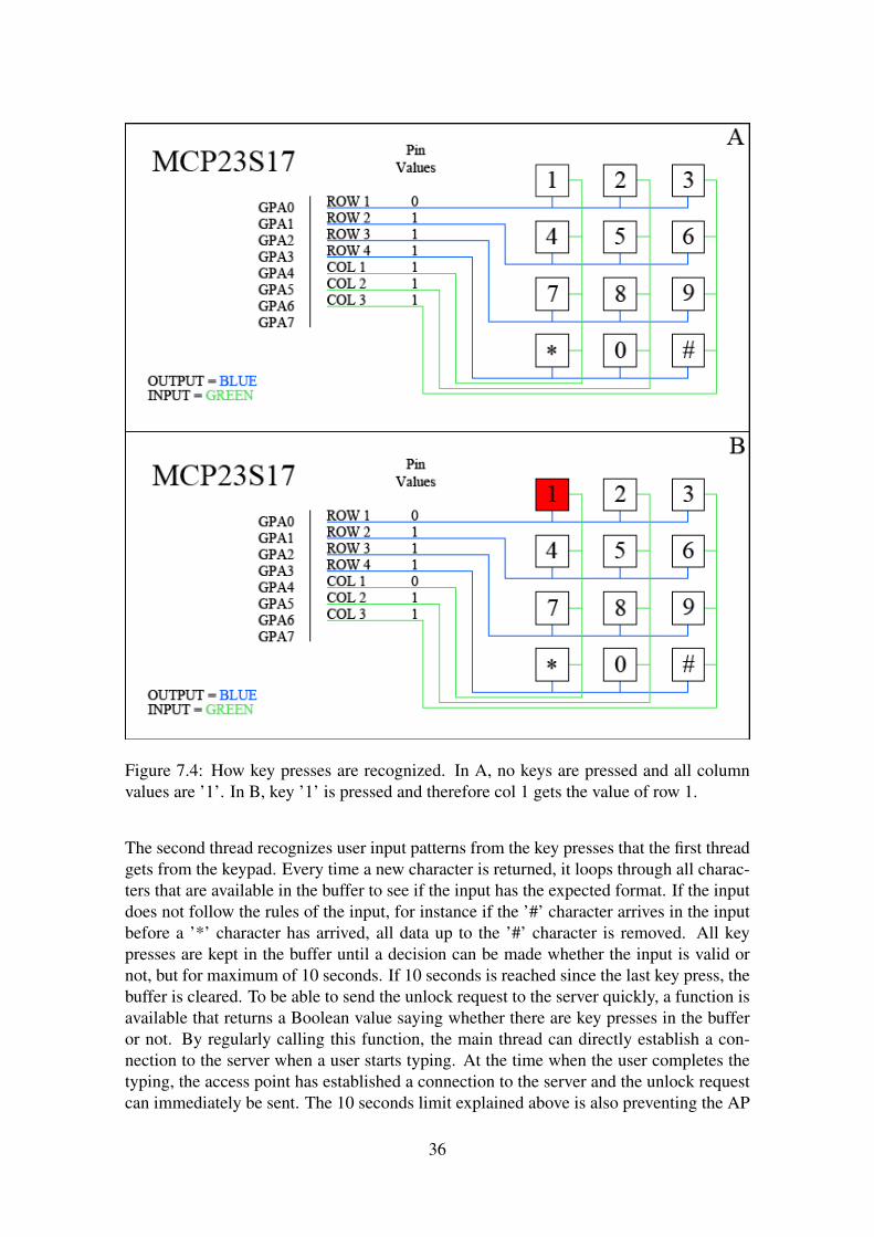
Figure 7.4: How key presses are recognized. In A, no keys are pressed and all columnvalues are ’1’. In B, key ’1’ is pressed and therefore col 1 gets the value of row 1.
The second thread recognizes user input patterns from the key presses that the first threadgets from the keypad. Every time a new character is returned, it loops through all charac-ters that are available in the buffer to see if the input has the expected format. If the inputdoes not follow the rules of the input, for instance if the ’#’ character arrives in the inputbefore a ’*’ character has arrived, all data up to the ’#’ character is removed. All keypresses are kept in the buffer until a decision can be made whether the input is valid ornot, but for maximum of 10 seconds. If 10 seconds is reached since the last key press, thebuffer is cleared. To be able to send the unlock request to the server quickly, a function isavailable that returns a Boolean value saying whether there are key presses in the bufferor not. By regularly calling this function, the main thread can directly establish a con-nection to the server when a user starts typing. At the time when the user completes thetyping, the access point has established a connection to the server and the unlock requestcan immediately be sent. The 10 seconds limit explained above is also preventing the AP
36
from being stuck in a state with an established connection to the server and just waitingfor user input.
7.2.6 Access Point Locked or Unlocked
As mentioned in the limitation part, section 1.3, the access point is not connected to a reallock, but instead two LEDs are used to indicate whether it is locked or unlocked. TheLEDs are located on the development board and can be seen in figure 7.5. To also informthe user that the access point really recognizes the key presses, these two LEDs starts toblink simultaneously as soon as a user presses the first key. They will keep doing thatuntil the unlock request is accepted/rejected or the input is considered invalid.
Figure 7.5: In A, the access point is locked and in B unlocked.
7.2.7 Inactivation of the Access Point
The access points can be inactivated from the server. When an access point is inactivated,it stops accepting user input and sending unlock requests. Since no unlock requests aresent, the load of the server is reduced compared with if the access points would functionnormally and just let the server reject all unlock requests for inactivated access points.Considering the flowchart in figure 7.2; when an access point is inactivated everythingdealing with user data is skipped. If an access point is set to be inactivated, it will applythe inactivation next time it connects. If a user tries to unlock an access point in thetime period between when the access point has been inactivated at the server side and theaccess point has received the inactivation, an unlock request will still not be sent. Sincewhen the access point sets up a connection to the server, the server will send the newconfiguration before it is time to send the unlock request and therefore the unlock requestwill be skipped.
7.2.8 Getting and Formatting the GPS Data
The 3G Broadband module used in the access point is equipped with a GPS receiver,which is used to let the server know where each access point is located. To enable theGPS, two different AT commands are sent to the module; one command for changing thesettings and one to start receiving the data. Those commands are added and explained
37
in Appendix A. The GPS data from this receiver is formatted in NMEA 0183 applica-tion layer protocol, which is explained in section 3.2.5. Each fix received from the GPSreceiver contains the position together with several other values. Those different valuesare:
• $GPGSV - GPS Satellites in View
• $GPGLL - Geographical Position, Latitude/Longitude
• $GPGGA - Global Positioning System Fix Data
• $GPGSA - GPS DOP and Active Satellites
• $GPGST - GPS Pseudorange Noise Statistics
• $GPRMC - Recommended Minimum Specific GPS/TRANSIT Data
What the server is interested in is the geographic position, which is a part of the $GPGLLrow above. An example of a $GPGLL row is given in listing 7.4.
$GPGLL, 5 7 4 2 . 3 1 9 7 ,N, 1 1 5 6 . 5 0 8 1 , E , 1 2 5 6 1 3 ,A∗1F
Listing 7.4: Latitude/Longitude position given in NMEA format.
The row in listing 7.4 contains the following: $GPGLL, latitude position, north or south,longitude position, east or west, time when fix is taken, data validity and a checksum.However, that row contains the position in NMEA format and not in decimal. Therefore,a conversion is required. To convert from NMEA to decimal the following formula isused:
toDecimal(x) = bx/100c+ ((x− (bx/100c ∗ 100))/60)
Here is an example when the NMEA data above is converted into decimal:
NMEA DecimalLatitude 5742.3197 N 57 + (42.3197 / 60) N = 57.705328 N = 57.705328Longitude 1156.5081 E 11 + (56.5081 / 60) E = 11.941801 E = 11.941801
In the example above, the latitude position is North and longitude is East. Those directionsdo not affect the decimal conversion. But if latitude would be South or longitude wouldbe West, the decimal representation is negative.
7.2.9 Updating the Firmware of a Module
When a firmware update is added to the system, the server decides when each accesspoint will be updated by sending the time to it. At the given time, the access point sendsa request to the server and the server starts to send the file to the access point. After acompleted file transmission, the access point first starts with closing the connection to theserver, closes the SSH tunnel and disconnects from the Internet. Updating the modulemeans that the connection to the Internet is lost, so at least closing the SSH tunnel is
38
important to be able to start it again after the update. Having everything closed, theupdate of the module is started and will be completed within 5 minutes.
7.3 Server Software
The server plays a crucial role in the system. It handles user authentication, firmwareupdates of the 3G Broadband Modules and also gives the administrator of the systema good overview of all access points. The server application is written in Java with agraphical user interface. This section gives a description of how the server application isimplemented.
7.3.1 Application implemented in MVC
Since the server application is developed with a graphical user interface, it follows themodel-view-controller design pattern, see section 3.2.4, to get well-structured code. Thefunctionality of the server is implemented in the model part, thus handling the connectionwith the access points, user authentication and the firmware updates. The windows arepart of the view and the controller handles the key presses and the mouse clicks made bythe user.
The communication between the model and the view is implemented with the Observer/Ob-servable interface available in the Java framework. When information is changed in themodel, the view is informed through the interface and can request new information fromthe model.
The controller is implemented as an action listener and is informed about the user interac-tion that is made in the view. When an event occurs, the controller calls the correspondingfunction in the model that will handle the required changes for that particular event.
The model is split into several classes to separate functionality; the view is split intoseveral classes to separate different parts of the view; the controller is split into severalclasses to just handle parts of the view.
7.3.2 Using a Database to Save Information
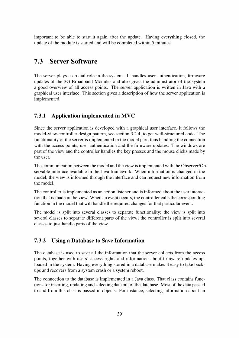
The database is used to save all the information that the server collects from the accesspoints, together with users’ access rights and information about firmware updates up-loaded in the system. Having everything stored in a database makes it easy to take back-ups and recovers from a system crash or a system reboot.
The connection to the database is implemented in a Java class. That class contains func-tions for inserting, updating and selecting data out of the database. Most of the data passedto and from this class is passed in objects. For instance, selecting information about an
39
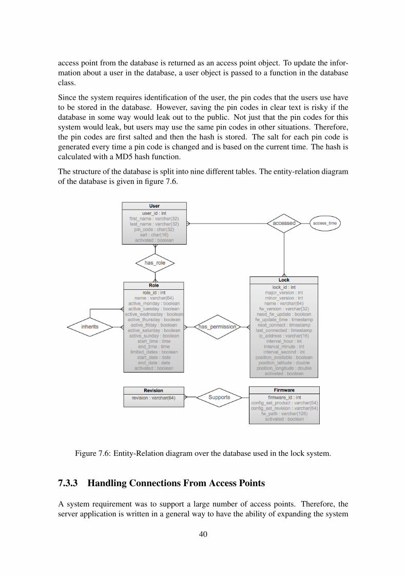
access point from the database is returned as an access point object. To update the infor-mation about a user in the database, a user object is passed to a function in the databaseclass.
Since the system requires identification of the user, the pin codes that the users use haveto be stored in the database. However, saving the pin codes in clear text is risky if thedatabase in some way would leak out to the public. Not just that the pin codes for thissystem would leak, but users may use the same pin codes in other situations. Therefore,the pin codes are first salted and then the hash is stored. The salt for each pin code isgenerated every time a pin code is changed and is based on the current time. The hash iscalculated with a MD5 hash function.
The structure of the database is split into nine different tables. The entity-relation diagramof the database is given in figure 7.6.
Figure 7.6: Entity-Relation diagram over the database used in the lock system.
7.3.3 Handling Connections From Access Points
A system requirement was to support a large number of access points. Therefore, theserver application is written in a general way to have the ability of expanding the system
40
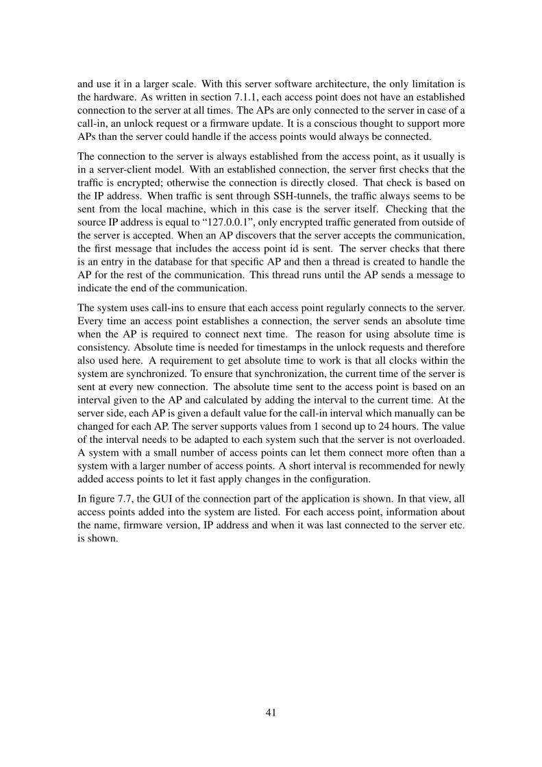
and use it in a larger scale. With this server software architecture, the only limitation isthe hardware. As written in section 7.1.1, each access point does not have an establishedconnection to the server at all times. The APs are only connected to the server in case of acall-in, an unlock request or a firmware update. It is a conscious thought to support moreAPs than the server could handle if the access points would always be connected.
The connection to the server is always established from the access point, as it usually isin a server-client model. With an established connection, the server first checks that thetraffic is encrypted; otherwise the connection is directly closed. That check is based onthe IP address. When traffic is sent through SSH-tunnels, the traffic always seems to besent from the local machine, which in this case is the server itself. Checking that thesource IP address is equal to “127.0.0.1”, only encrypted traffic generated from outside ofthe server is accepted. When an AP discovers that the server accepts the communication,the first message that includes the access point id is sent. The server checks that thereis an entry in the database for that specific AP and then a thread is created to handle theAP for the rest of the communication. This thread runs until the AP sends a message toindicate the end of the communication.
The system uses call-ins to ensure that each access point regularly connects to the server.Every time an access point establishes a connection, the server sends an absolute timewhen the AP is required to connect next time. The reason for using absolute time isconsistency. Absolute time is needed for timestamps in the unlock requests and thereforealso used here. A requirement to get absolute time to work is that all clocks within thesystem are synchronized. To ensure that synchronization, the current time of the server issent at every new connection. The absolute time sent to the access point is based on aninterval given to the AP and calculated by adding the interval to the current time. At theserver side, each AP is given a default value for the call-in interval which manually can bechanged for each AP. The server supports values from 1 second up to 24 hours. The valueof the interval needs to be adapted to each system such that the server is not overloaded.A system with a small number of access points can let them connect more often than asystem with a larger number of access points. A short interval is recommended for newlyadded access points to let it fast apply changes in the configuration.
In figure 7.7, the GUI of the connection part of the application is shown. In that view, allaccess points added into the system are listed. For each access point, information aboutthe name, firmware version, IP address and when it was last connected to the server etc.is shown.
41
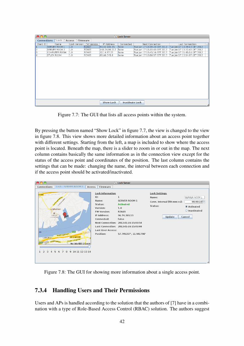
Figure 7.7: The GUI that lists all access points within the system.
By pressing the button named “Show Lock” in figure 7.7, the view is changed to the viewin figure 7.8. This view shows more detailed information about an access point togetherwith different settings. Starting from the left, a map is included to show where the accesspoint is located. Beneath the map, there is a slider to zoom in or out in the map. The nextcolumn contains basically the same information as in the connection view except for thestatus of the access point and coordinates of the position. The last column contains thesettings that can be made: changing the name, the interval between each connection andif the access point should be activated/inactivated.
Figure 7.8: The GUI for showing more information about a single access point.
7.3.4 Handling Users and Their Permissions
Users and APs is handled according to the solution that the authors of [7] have in a combi-nation with a type of Role-Based Access Control (RBAC) solution. The authors suggest
42
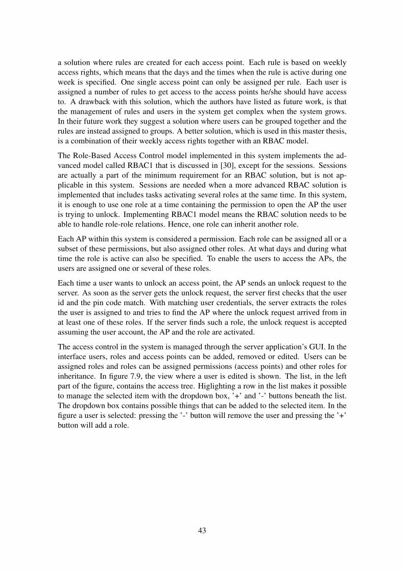
a solution where rules are created for each access point. Each rule is based on weeklyaccess rights, which means that the days and the times when the rule is active during oneweek is specified. One single access point can only be assigned per rule. Each user isassigned a number of rules to get access to the access points he/she should have accessto. A drawback with this solution, which the authors have listed as future work, is thatthe management of rules and users in the system get complex when the system grows.In their future work they suggest a solution where users can be grouped together and therules are instead assigned to groups. A better solution, which is used in this master thesis,is a combination of their weekly access rights together with an RBAC model.
The Role-Based Access Control model implemented in this system implements the ad-vanced model called RBAC1 that is discussed in [30], except for the sessions. Sessionsare actually a part of the minimum requirement for an RBAC solution, but is not ap-plicable in this system. Sessions are needed when a more advanced RBAC solution isimplemented that includes tasks activating several roles at the same time. In this system,it is enough to use one role at a time containing the permission to open the AP the useris trying to unlock. Implementing RBAC1 model means the RBAC solution needs to beable to handle role-role relations. Hence, one role can inherit another role.
Each AP within this system is considered a permission. Each role can be assigned all or asubset of these permissions, but also assigned other roles. At what days and during whattime the role is active can also be specified. To enable the users to access the APs, theusers are assigned one or several of these roles.
Each time a user wants to unlock an access point, the AP sends an unlock request to theserver. As soon as the server gets the unlock request, the server first checks that the userid and the pin code match. With matching user credentials, the server extracts the rolesthe user is assigned to and tries to find the AP where the unlock request arrived from inat least one of these roles. If the server finds such a role, the unlock request is acceptedassuming the user account, the AP and the role are activated.
The access control in the system is managed through the server application’s GUI. In theinterface users, roles and access points can be added, removed or edited. Users can beassigned roles and roles can be assigned permissions (access points) and other roles forinheritance. In figure 7.9, the view where a user is edited is shown. The list, in the leftpart of the figure, contains the access tree. Higlighting a row in the list makes it possibleto manage the selected item with the dropdown box, ’+’ and ’-’ buttons beneath the list.The dropdown box contains possible things that can be added to the selected item. In thefigure a user is selected: pressing the ’-’ button will remove the user and pressing the ’+’button will add a role.
43
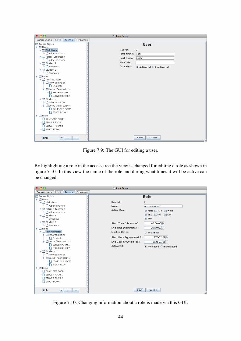
Figure 7.9: The GUI for editing a user.
By highlighting a role in the access tree the view is changed for editing a role as shown infigure 7.10. In this view the name of the role and during what times it will be active canbe changed.
Figure 7.10: Changing information about a role is made via this GUI.
44
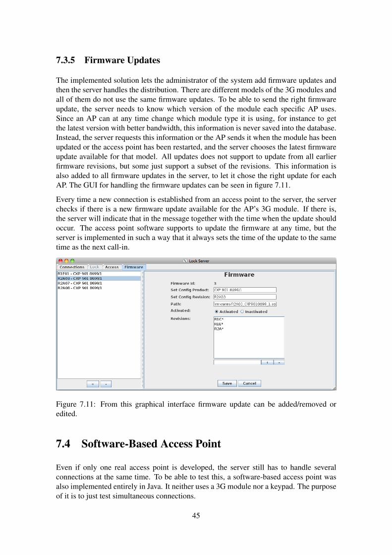
7.3.5 Firmware Updates
The implemented solution lets the administrator of the system add firmware updates andthen the server handles the distribution. There are different models of the 3G modules andall of them do not use the same firmware updates. To be able to send the right firmwareupdate, the server needs to know which version of the module each specific AP uses.Since an AP can at any time change which module type it is using, for instance to getthe latest version with better bandwidth, this information is never saved into the database.Instead, the server requests this information or the AP sends it when the module has beenupdated or the access point has been restarted, and the server chooses the latest firmwareupdate available for that model. All updates does not support to update from all earlierfirmware revisions, but some just support a subset of the revisions. This information isalso added to all firmware updates in the server, to let it chose the right update for eachAP. The GUI for handling the firmware updates can be seen in figure 7.11.
Every time a new connection is established from an access point to the server, the serverchecks if there is a new firmware update available for the AP’s 3G module. If there is,the server will indicate that in the message together with the time when the update shouldoccur. The access point software supports to update the firmware at any time, but theserver is implemented in such a way that it always sets the time of the update to the sametime as the next call-in.
Figure 7.11: From this graphical interface firmware update can be added/removed oredited.
7.4 Software-Based Access Point
Even if only one real access point is developed, the server still has to handle severalconnections at the same time. To be able to test this, a software-based access point wasalso implemented entirely in Java. It neither uses a 3G module nor a keypad. The purposeof it is to just test simultaneous connections.
45

The software-based access point was developed early in the project which turned out to begood. It was advantageous to use the software-based access point in situations when thedevelopment of the server and the access point programs were independent, for instancethe user management for the server and getting the module to work with the access pointprogram. The development of these programs were made in parallel and therefore it wasnot always possible to test the functionality of the server with the physical access point,since required functionality was not implemented yet. A graphical user interface was alsodeveloped for the software-based access point to easily demonstrate the system. The GUIcan be seen in figure 7.12.
However, the software-based access point does not implement the full functionality thatthe physical access point does. Since the software-based access point does not use a 3Gmodule, there was no reason of implementing this functionality in the program.
Figure 7.12: The graphical interface for the software-based access point.
46
Chapter 8
Summary
The server application is programmed according to the Model-View-Controller designpattern to separate the view from the code that handles the server’s internal functionality.From the graphical user interface the whole functionality of the server can be seen andhandled; getting an overview of all access points and add new firmware and new users tothe system. To be able to handle a larger set of users, the management of the users andtheir access rights is based on Role-Based Access Control. Each user can be given a name,a pin code and whether the user is activated or inactivated. To assign permissions to theusers, each user is also given different roles. For each role, times and days are specifiedto configure when it will be active along with the permissions (access points) that areincluded. A role can inherit the permissions of other roles as well. A functionality thathandles the firmware updates is added to be able to update the 3G Broadband modules andit is implemented to support future 3G Broadband modules. The server has the firmwareupdates and which one it chooses to send is based on the information that each accesspoint sends to the server about its module. The server makes the decision if and when anaccess point will be updated and in such a situation the file is distributed in pieces fromthe server to the access point.
The access point is based on a development board called BeagleBoard-xM that runs aLinux kernel. It gets its Internet connection from a 3G Broadband module connected viaUSB and uses a keypad, which is connected via SPI, to get user input. The access pointestablishes a connection to the server only when information is exchanged; i.e. whenunlock requests are sent, a firmware update is needed or it is time for a call-in. A call-in isa time given by the server that defines when the access point is required to connect to theserver if nothing has happened since the last connection. The access point uses two LEDsto indicate whether it is unlocked or locked, instead of using a real lock. When the accesspoint receives a response from an unlock request, it indicates the result by lightning theLED that represents the outcome of the unlock request.
When the user starts to type on the keypad, the access point establishes an encryptedconnection to the server. This is done to minimize the time to get back the result from anunlock request. The average time it takes from the point when the user has finished typinguntil the access point shows the result of the unlock request is about one second.
47

The implemented system is a well functional electronic lock system based on 3G Broad-band modules. The central server is able to handle many concurrent access points. Theserver has the information of where and when users have access to the different locations,so at every unlock request the server is contacted to make the decision whether to unlockthe access point or not. The system uses 3G to get an Internet connection and that worksvery well. The connection does not have any negative effects on the functionality andworks at least as good as a wired connection.
48
Chapter 9
Discussion and Conclusions
In this chapter we discuss the results of this master thesis and how some parts of imple-mentation could have been done differently.
As mentioned in the summary chapter, the average time for an unlock request was aboutone second. Depending on situation, one second can be considered too long and alsoannoying. In this solution, the user id and pin code is sent to the server at the same time.When the server has received the user credentials, the server checks if it is correct and ifthe user has access to that access point. To minimize the time, the user id can instead besent as soon as the user has entered it. The server prepares the unlock response by lookingat the access rights of the user to decide whether to accept or reject it and then waits forthe pin code. If the received pin code matches the one stored in the system, the serverwill respond with the prepared result, otherwise the unlock request is rejected. Whenthe server decides whether an unlock request is accepted or rejected, it loops through theuser’s roles and tries to find a role including the access point. Hence, this operation isheavier for users with a large number of roles than users with a small number. In thisalternative solution, this operation is done when the user id is received instead of doing itafter when the pin code is received, which means that the biggest response time reductionwould be seen for users with a large number of roles.
Testing of the physical access point was only done at the office, where full 3G coveragewas available, which means that no testing was done when the access point was connectedto the Internet with just EDGE or GPRS coverage. However, the relevance of testing thetime it would take with EDGE or GPRS coverage can be discussed since the coverage isimproved all the time.
The testing of the server was done with just one single real access point. A software-based access point was implemented to be able to test the most crucial part of the serverwith several access points; not including the firmware update functionality. If 3G moduleinformation would have been simulated in the software-based access point, even tests ofthe sending the firmware updates could have been done more thoroughly. The systemworked well for updating one access point with new firmware, but the system should alsobe tested with simultaneous transfers.
The encryption between the access points and the server was based on SSH tunnels. There
49

was one single drawback with using SSH and that was when access points were added.When using SSH, host keys are preferably used to connect to the remote machine. Addinga new access point means that a key also has to be installed on the server side. This processis currently not automated, since there is no good way of knowing if the key belongs tothe right access point. At the moment, there is also no connection between the ID of anaccess point and the key installed at the server side. But it is hard to tell if access pointsshould be automatically added to the system or not? Maybe it is good enough to manuallyadd access points to be sure they are legitimate.
Overall, the system works well and the issues discussed above are actually small problemsthat do not really affect the result of the demo system. Those things would have been fixedif more time were available or if a real product would be produced.
50
Chapter 10
Future Work
A further extension to this master thesis and to the access point used in this system willbe to port the application to the 3G Broadband module. That means to eliminate thedevelopment board and run the access point program directly on the module’s processorand to decrease the physical size and reduce costs and power consumption of the accesspoint. As it is now, the firmware of the 3G Broadband module is updated externally fromthe development board to the module via USB and the update is only installed by themodule if it is signed by Ericsson. But executing a program on the same processor as themodule’s firmware introduces a code separation problem; the ported application cannotinterfere with the execution of the firmware.
Considering the hardware, the access point should in the future be equipped with anRFID- or magnetic card reader to improve the security. At the moment, knowing theuser id and pin code is enough to get access. If the user is also given a physical badge or acard, it is not enough to just steal someone’s code to get access. Having a physical objectalso makes it easier to discover a loss than to discover that someone knows the pin code.Preferably, the access point can also be equipped with an LCD to easily inform the userabout the access point status.
The access points are only connected to the server when data is exchanged to easen theburden on the server and at the same time support more access points. As it is imple-mented, the time when the access point should connect next time is sent from the server.Every time an access point connects, it gets a new time that is only based on current timeplus the interval given to that access point. To get a better distribution over time, the servershould be able to schedule every call-in the access points do instead of just using an in-terval. Additionally, the server should implement a separate scheduling for the firmwareupdates. As it is now, the server only gives the access point an absolute time, which is thesame time as the next call-in. The scheduling of the updates should be done in such a waythat they do not occur at the same time and the time of the update could be adjusted suchthat it occurs when the access point is used the least.
51
Bibliography
[1] Nationalencyklopedi. mobiltelefoni. Swedish. Available at URL:www.ne.se/lang/mobiltelefoniAccessed January 7, 2012.
[2] Telia.se - Telias och Tele2s gemensamma turbo-3G nät bäst i test. Swedish.Available at URL:http://nyheter.telia.se/2176/telias-och-tele2s-gemensamma-turbo-3g-nat-bast-i-test/Accessed January 7, 2012
[3] Telia.se - Täckningskarta. Swedish. Available at URL:http://www.telia.se/privat/mobilt-bredband/merom/tackningskarta/tackningskarta.pageAccessed January 7, 2012
[4] Apple.com - iPad Technical Specifications. Available at URL:http://www.apple.com/ipad/specs/Accessed January 7, 2012
[5] Li Ping, Liao Jingsheng, Hu Chao, Yin Yong, Meng Max Q.-H. Design of MedicalRemote Monitoring System Base on Embedded Linux. Proceeding of the IEEE Inter-national Conference on Information and Automation. June 2011; Shenzhen, China;pp. 590-594.
[6] Cai Li, Zhang Wenya, Li En, Liang Zize, Hou Zeng-Guang, Tan Min. Design and Im-plementation of a CDMA-Based Remote Monitoring and Controlling System. SICEAnnual Conference 2007. Sept. 17-20, 2007; Kagawa, Japan; pp. 2445-2450.
[7] Daradimos Ilias, Papadopoulos Konstantinos, Stavrakas Ilias, Kaitsa Maria, Konto-giannis Theophanis, Triantis Dimos. A Physical Access Control System that utilizesexisting networking and computer infrastructure. EUROCON 2007: The InternationalConference on "Computer as a Tool". Sept. 9-12, 2007; Warsaw, Poland. pp. 501-504.
[8] Popa M., Popa S., Marcu M.. A Distributed Smart Card Based Access Control Sys-tem. SISY 2010: IEEE 8th International Symposium on Intelligent Systems and In-formatics. Sept. 10-11, 2010. Subotica, Serbia. pp. 341-346.
[9] Hwang Il-Kyu, Baek Jin-Wook. Wireless Access Monitoring and Control Systembased on Digital Door Lock. IEEE Transactions on Consumer Electronics, Vol. 53,No. 4. Nov, 2007; pp. 1724-1730.
52
[10] ZigBee - Specifications. Available at URL:http://www.zigbee.org/Specifications/ZigBee/FAQ.aspxAccessed January 7, 2012.
[11] Bhargav Ajay. Martix Keypad Interfacing with Microcontrollers: Introduction.Available at URL:http://www.8051projects.net/keypad-interfacing/introduction.phpAccessed January 14, 2012.
[12] Kalinsky David, Kalinsky Roee. Introduction to Serial Peripheral Interface.Available at URL:http://www.eetimes.com/discussion/beginner-s-corner/4023908/Introduction-to-Serial-Peripheral-InterfaceAccessed January 14, 2012.
[13] Bies, Lammert. Hayes modem AT command set. Available at URL:http://www.lammertbies.nl/comm/info/hayes-at-commands.htmlAccessed January 22, 2012
[14] AT Command Manual. Ericsson. 2009.
[15] BuildRoot - About. Available at URL:http://buildroot.uclibc.org/about.htmlAccessed January 14, 2012.
[16] Introduction to cross-compiling for Linux. Available at URL:http://landley.net/writing/docs/cross-compiling.htmlAccessed January 14, 2012.
[17] Model/View Programming. Available at URL:http://developer.qt.nokia.com/doc/qt-4.8/model-view-programming.htmlAccessed January 21, 2012.
[18] Betke, Klaus. The NMEA 0183 Protocol. May 2000. Available at URL:www.tronico.fi/OH6NT/docs/NMEA0183.pdfAccessed January 21, 2012.
[19] Protocol Buffers - Developers Guide. Available at URL:http://code.google.com/intl/sv-SE/apis/protocolbuffers/docs/overview.htmlAccessed October, 2011.
[20] Mochel Patrick, The sysfs Filesystem. Available at URL:www.kernel.org/pub/linux/kernel/people/mochel/doc/papers/ols-2005/mochel.pdfAccessed January 21, 2012
[21] Apache.org - Thrift. Available at URL: http://thrift.apache.orgAccessed October, 2011.
[22] BeagleBoard-xM System Rev C Reference Manual Revision 1.0.beagleboard.org. 2010.
[23] Datasheet for MCP23S17. Microship Technology Inc. 2007.
53
[24] eLinux.org - BeagleBoard/SPI/Patch-2.6.32. Available at URL:http://elinux.org/BeagleBoard/SPI/Patch-2.6.32Accessed November 7, 2011.
[25] SD/MMC format for OMAP3 boot. Available at URL:http://processors.wiki.ti.com/index.php?title=MMC_Boot_FormatAccessed October 25, 2011.
[26] Boot Sequence. Available at URL:http://processors.wiki.ti.com/index.php/Boot_SequenceAccessed October 25, 2011.
[27] TI AM/OMAP Booting and Flash Recovery. Available at URL:http://community.qnx.com/sf/wiki/do/viewPage/projects.bsp/wiki/AM_OMAP_boot_resourcesAccessed October 25, 2011.
[28] Protocol Buffers - Techniques. Available at URL:http://code.google.com/intl/sv-SE/apis/protocolbuffers/docs/techniques.htmlAccessed October, 2011.
[29] Belokosztolszki, András. Role-based access control policy administration. 2004.
[30] Sandhu Ravi S., Coyne Edward J., Feinstein Hal L.. Role-Based Access ControlModels. Computer, Vol. 29 Issue 2. Feb, 1996; pp. 38-47.
54
Appendix A
AT Commands
• AT+CPIN? - This command checks whether the SIM card is protected by a PINcode or not. The return value says READY if it is not protected and otherwise whattype of code that needs to be input; PIN, PUK etc.
• AT+CPIN - This command is used to unlock the SIM card by sending the PIN orPUK code to it.
• AT+CFUN - This command is used to turn on the module. There are differentmodes for the module: fully functional mode, energy-saving mode etc. The modeis given as a parameter to the command.
• AT+CGDCONT - Used to configure the Access Point Name (APN) of the module.
• AT*ENAP - The USB Ethernet Emulation is enabled or disabled with this com-mand.
• AT*ENAP? - This command is used to check the status of the connection. Whichis disconnected, connected or connection in progress.
• AT*E2GPSCTL - Command used for enabling or disabling the GPS receiver. Asa parameter the command is given an interval for how often gps positions will bereturned.
• AT*E2GPSNPS - With this command a virtual USB COM port is activated forGPS (NMEA) output.
• AT*EEVINFO - A call to this command returns information about the module.
• AT*CGPADDR - This command returns the IP address of the module.
55