DEVELOPMENT AND CHARACTERIZATION BETWEEN POLYETHERSULFONE...
25
DEVELOPMENT AND CHARACTERIZATION BETWEEN POLYETHERSULFONE/POLYSULFONE (PES/PSF) MICIBLE BLEND WITH PRIMARY POLYMER (PES AND PSF) MEBRANE FOR O 2 /N 2 SEPARATION SUFINAH BT YUSSOF A thesis submitted in fulfillment of the requirements for the award of the Degree of Bachelor of Chemical Engineering (Gas Technology) Faculty of Chemical & Natural Resources Engineering Universiti Malaysia Pahang DECEMBER 2010
Transcript of DEVELOPMENT AND CHARACTERIZATION BETWEEN POLYETHERSULFONE...

DEVELOPMENT AND CHARACTERIZATION BETWEEN
POLYETHERSULFONE/POLYSULFONE (PES/PSF) MICIBLE BLEND WITH
PRIMARY POLYMER (PES AND PSF) MEBRANE FOR O2/N2 SEPARATION
SUFINAH BT YUSSOF
A thesis submitted in fulfillment
of the requirements for the award of the Degree of
Bachelor of Chemical Engineering (Gas Technology)
Faculty of Chemical & Natural Resources Engineering
Universiti Malaysia Pahang
DECEMBER 2010

v
ABSTRACT
Membrane technology becomes more interesting in industrial level for gas
separation and purification. Main problem in membrane technology industries is hard
to find membrane that high performance both in selectivity and permeability.
Membrane that provide high permeability offered low selectivity and vice versa.
Therefore, blend polymer is introduced to overcome this problem. Means that,
beneficial properties of polymers are combining in one single material. In this study,
four difference compositions of dope solutions have prepared which are 25%
polyethersulfone (PES), 25% polysulfone (PSF), 20% polyethersulfone 5%
polysulfone (PES/PSF) and 5% polyethersulfone 20% polysulfone (PES/PSF) in
order to prepared the asymmetric membrane. The membrane was fabricated by using
dry/wet phase inversion technique. Two type of membrane were produced from each
of the sample membrane which are coated and uncoated membrane. The coating
membrane was coated by coating agent, polydimethylsiloxane (PDMS). The
performance of the membrane was evaluated by gas permeation unit with pure
oxygen (O2) and nitrogen (N2) as a test gaseous. From the result, PES/PSF blend
polymers show the best result compared the others, where the permeability value for
O2 is about 19.93 GPU and N2 is 14.95 GPU whereas the selectivity of O2/N2 is 1.33.
The lowest selectivity can be achieved by using primary polymer dope solution of
PES and the selectivity for O2/N2 is 1.12 where the permeability of O2 is 91.84 GPU
and N2 is 82.07 GPU. At 25% total polymer show not many difference to the
selectivity. This is because only small amount of second polymer was added in order
to blend the polymer. Then, the membrane morphology was characterized by
Scanning Electron Microscopy (SEM) for identified the surface structure and cross
section of the membrane. Cross section for blend polymer show the pore is smallest
than primary polymer while surface structure for coated membrane is smooth as
compared to uncoated membrane. From this study, by blending two type of polymer
increase the performance of the membrane.

vi
ABSTRAK
Teknologi membran menjadi sangat terkenal di peringkat industri dalam
proses pemisahan dan penulinan gas. Masalah utama dalam teknologi membran ialah
sukar untuk mendapatkan membran yang berprestasi tinggi iaitu membran yang
mempunyai kadar pemisahan yang tinggi dan kadar pemilihan yang tinggi dalam
masa yang sama. Ini kerana membran yang mmpunyai kadar pemisahan yang tinggi
akan mempunyai kadar pemilihan yang rendah dan begitulah sebaliknya. Oleh
kerana itu, polimer campuran diperkenalkan bagi menagatasi masalah tersebut.
Dalam kaedah ini, kebaikan yang ada pada dua polimer digabungkan menjadi dalam
satu bahan. Dalam kajian ini, empat larutan pekat yang berbeza iaitu 25%
polyethersulfone (PES), 25% polysulfone (PSF), 20% polyethersulfone 5%
polysulfone (PES/PSF) dan 5% polyethersulfone 20% polysulfone (PES/PSF)
disediakan untuk menyediakan asymmetric membran. Teknik yang digunakan ialah
pembalikan fasa kering/basah. Dua jenis membran dihasilkan daripada semua sampel
membran iaitu bersalut dengan agen salutan polydimethylsiloxane (PDMS) dan tidak
bersalut. Prestasi semua membran diuji dengan alat penyerapan gas menggunakan
gas oksigen (O2) dan nitrogen (N2) tulen. Daripada keputusan yang diperolehi,
campuran polymer PES/PSF menunjukkan keputusan yang baik daripada yang lain,
dimana kadar serapan untuk O2 ialah 19.93 GPU dan N2 ialah 14.95 GPU manakala
kadar pemilihan O2/N2 ialah 1.33. Kadar pemilihan yang rendah diperolehi dengan
menggunakan larutan pekat primary polymer PES dan kadar pemilihan O2/N2 ialah
1.12 dimana kadar pemisahan untuk O2 ialah 91.84 GPU dan N2 ialah 82.07 GPU.
Kadar pemilihan mununjukkan tidak banyak perbezaan pada jumlah polymer 25%.
Hanya jumlah yang kecil untuk polymer yang kedua ditambahkan kepada polymer
yang pertama untuk menghasilkan campuran polymer. Hasil membran kemudiannya
akan dianalisa untuk mengenal pasti struktur permukaan dan keratan rentas membran
tersebut dengan menggunakan Scanning Electron Microscopy (SEM). Keratan rentas
menunjukkan liang bagi campuran polymer adalah kecil berbanding primary polymer
manakala struktur permukaan membran yang bersalut adalah lebih licin berbanding
yang tidak bersalut. Daripada kajian ini, didapati campuran dua jenis polymer
menunjukkan peningkatan terhadap prestasi membran.

vii
TABLE OF CONTENTS
CHAPTER TITLE PAGE
DECLARATION ii
DEDICATION iii
ACKNOWLEDGEMENT iv
ABSRTACT v
ABSTRAK vi
TABLE OF CONTENT vii
LIST OF TABLES xi
LIST OF FIGURES xii
LIST OF SYMBOLS xv
LIST OF ABBREVIATIONS xvi
1 INTRODUCTION
1.1 Background of the Study 1
1.2 Problem Statement 3
1.3 Objective of the Study 4

viii
1.4 Scope of the Study 4
2 LITERATURE REVIEW
2.1 Definition of Membrane 5
2.2 History of Gas Separation 6
2.3 Membrane Modules 7
2.3.1 Plate-and Frame Modules 7
2.3.2 Spiral Wound Modules 8
2.3.3 Hollow Fiber Modules 9
2.3.4 Tubular Modules 11
2.4 Membrane Materials 12
2.4.1 Polymeric Membranes 12
2.4.2 Ceramic and Zeolite Membrane 13
2.5 Type of Membrane 14
2.6 Advantages and Disadvantages Polymer Membrane 15
2.6.1 Advantages of Membrane Technology 15
2.6.2 Disadvantages of Polymer Membrane 16
2.7 Oxygen/Nitrogen for Membrane Separation 16
2.8 Parameter in Gas Separation System 17
2.8.1 Permeability of the Membrane 17
2.8.2 Selectivity of the Membrane 18
2.9 Polymer Blend 18

ix
2.9.1 Effect of Blending Polymer to the Membrane 18
3 METHODOLOGY
3.1 Research Design 20
3.2 Materials 21
3.2.1 Polysulfone (PSF) 21
3.2.2 Polyethersulfone (PES) 22
3.2.3 N-Methyl-2-Pyrrolidone (NMP) 23
3.2.4 Water 24
3.2.5 Methanol 25
3.2.6 Polydimethylsiloxane (PDMS) 26
3.2.7 N-hexane as Coating Agent Solvent 27
3.2.8 Oxygen and Nitrogen as Test Gas 28
3.3 Preparation of Dope Formulation 29
3.4 Turbidity Titration Test 30
3.5 Preparation of Membrane Casting 31
3.6 Membrane Coating 32
3.7 Membrane Characterization 32
3.7.1 Membrane Testing Using Gas Permeation Unit 32
3.7.2 Morphology of Membrane Using Scanning
Electron Microscopy (SEM)
34

x
4 RESULT AND DISCUSSION
4.1 Turbidity Titration for Dope Formulation 35
4.2 Effect of Different Polymer Concentration on Uncoated
Membrane for O2/N2 Separation
37
4.3 Effect of Different Polymer Concentration on Coated
Membrane for O2/N2 Separation
44
5 CONCLUSION AND RECOMMENDATION
5.1 Conclusion 51
5.2 Recommendation 52
REFERANCES 54
APPENDICES
Appendix A1 57
Appendix A2 58
Appendix A3 59
Appendix A4 60
Appendix A5 61

xi
LIST OF TABLES
TABLE NO. TITLE PAGE
3.1 Physical properties of polysulfone 21
3.2 Physical properties of water 24
3.3 Physical properties of methanol 25
3.4 Physical properties of polydimethylsiloxane (PDMS) 26
3.5 Physical properties of n-hexane 27
3.6 Physical properties of oxygen and nitrogen 28
4.1 Comparison of dope formulation before and after turbidity
titration test
36
4.2 Performance of uncoated membrane for O2/N2 separation 37
4.3 Performance of coated membrane for O2/N2 separation 44

xii
LIST OF FIGURES
FIGURE NO. TITLE PAGE
2.1 Schematic diagram permeation of membrane 5
2.2 Schematic drawing of plate and frame module 8
2.3 Schematic drawing of spiral wound module 9
2.4 Illustrated design of hollow fiber module, shell side feed 10
2.5 Illustrated design of hollow fiber module bore side feed 11
2.6 Typical tubular module design 11
2.7 Schematic drawing of defect sealing on selective layer 12
2.8 Schematic drawing of two layer composite membrane 13
2.9 Illustrated of cross sections of asymmetric membrane 14
2.10 Illustrated of cross sections for asymmetric membrane 15
3.1 Research design 20
3.2 Polysulfone structure 21
3.3 Polyethersulfone structure 22
3.4 N-Methyl-2-pyrrolidone structure 23
3.5 Water structure 24
3.6 Methanol structure 25
3.7 Polydimethylsiloxane (PDMS) structure 26
3.8 N-hexane structure 27
3.9 Dope solution preparation vessel 30
3.10 Membrane casting unit 31
3.11 Gas permeation unit 33
4.1 Selectivity versus pressure of uncoated membrane for
O2/N2 separation
38

xiii
4.2 Permeability versus pressure of uncoated membrane for
O2/N2 separation
38
4.3 Image of cross section for uncoated primary polymer
membrane 25% PES
40
4.4 Image of cross section for uncoated primary polymer
membrane 25% PSF
40
4.5 Image of cross section for uncoated blend polymer
membrane contain of 20% PES + 5% PSF
41
4.6 Image of cross section for uncoated blend polymer
membrane contain of 20% PSF + 5% PES
41
4.7 Image of surface structure for uncoated primary
polymer membrane 25% PES
42
4.8 Image of surface structure for uncoated membrane for
primary polymer membrane 25% PSF
42
4.9 Image of surface structure for uncoated blend polymer
membrane contains of 20% PES + 5% PSF
43
4.10 Image of surface structure for uncoated blend polymer
membrane contains of 20% PSF + 5% PES
43
4.11 Selectivity versus pressure of coated membrane for
O2/N2 separation
45
4.12 Permeability versus pressure of uncoated membrane for
O2/N2 separation
46
4.13 Image of cross section for coated primary polymer
membrane 25% PES
47
4.14 Image of cross section for coated primary polymer
membrane 25% PSF
47
4.15 Image of cross section for coated blend polymer
membrane contain of 20% PES + 5% PSF
48
4.16 Image of cross section for coated blend polymer
membrane contain of 20% PES + 5% PSF
48
4.17 Image of surface structure for coated primary polymer
membrane 25% PES
49
xiv
4.18 Image of surface structure for coated primary polymer
membrane 25% PSF
50
4.19 Image of surface structure for uncoated blend polymer
membrane contains of 20% PES + 5% PSF
50
4.20 Image of surface structure for uncoated blend polymer
membrane contains of 20% PSF + 5% PES
51

xv
LIST OF SIMBOLS
Q -Flowrate of supplied gas
A -Area
P -Trans membrane pressure
α -Selectivity
-Permeability of O2
-Permeability of N2

xvi
LIST OF ABBREVIATIONS
PES Polyethersulfone
PSF Polysulfone
PVDF Polyvinylidene diflofide
PP Polypropylene
PI Polyimide
NMP N-Methyl-2-Pyrrolidone
PDMS Polydimethylsiloxane
GPU Gas Permeation Unit
O2 Oxygen
N2 Nitrogen
SEM Scanning Electron Microscopy

CHAPTER 1
INTRODUCTION
1.1 Background of Study
Nowadays, membrane technology for gas separation and purification process
has been interesting. This is mainly due to relatively higher reliability, energy
efficiency and lower capital cost than other conventional gas separation process (Paul
et al and Stern, 1994).
Enriched nitrogen production from air, hydrogen separation in ammonia
plants and refineries, removal of carbon dioxide from natural gas, removal of volatile
organic compound such as ethylene or propylene from mixture with light gases such
as nitrogen in polyolefin purge gas purification and water vapor removal from air are
the most widely practice separations (Baker, 2000; Ghosal et al, 1994; Zolandz et al,
1992).
Membranes have a small footprint where space is limit or where portability.
These make them ideal for use in application on offshore platforms, aboard aircraft
and refrigerated shipping containers (Baker, 2000).

2
Many commercial polymeric membrane materials that have good chemical,
thermal and mechanical stability is such as polysulfone (PSF), polyethersulfone
(PES), polyvinylidene diflofide (PVDF), polypropylene (PP) and nylon
Polymeric materials such as polysulfone (PSF), polyethersulfone (PES) and
polyimide (PI) gives high selectivity coefficient and acceptable permeability value
for separation of gas mixture (Vu, 2001).
The permeability coefficient will vary from one gas to the next depends on a
given polymer and its property that allows the polymer to separate gas mixture.
Oxygen (O2) is always more permeable than nitrogen (N2) in all polymers.
Ratio of O2 to N2 permeability, the selectivity varies from 1.6 to 7.8 with given
materials. As the permeability of polymer to oxygen increase, its selectivity will be
decrease (Freemen, 1999; Robeson, 1991).
One of the methods to improve the properties of a polymer is by blending
with another polymer those posses some desired physical and chemical properties.
By using this blending polymer method give ideal separation factor for O2/N2 (Ismail
et al, 2008). Polymer blending method establish as excellent candidate membrane for
separation of gaseous mixture in industrial level. Thus, this method can develop in
perspective for future commercial application (Kapantaidakis et al, 2002).
3
1.2 Problem Statement
Gas separation with polymer membrane is rapidly becoming a mainstream
technology. The main problem in membrane technology is hard to find high
performances with both selectivity and permeability. Most of membranes selectivity
is inversely proportional with permeability.
PSF and PES are high performance engineering polymer. It has good
stability, permeability, selectivity, high critical pressure of plasticization and low cost
(Ding et al and Ismail et al, 2008; Li et al, 2004; Kapantaidakis et al, 2002).
Polymers with higher gas permeability have lower selectivity (Kapantaidakis,
1999; Robeson, 1991). This fact becomes a factor for looking towards polymer
blending methods to combine the properties of different materials and as versatile
tool to combine the beneficial properties of two or more components in one single
material (Li et al, 2001; Park et al, 2000).
Therefore, to overcome the problem, by blending the polymer is one of the
attractive of tuning the performance of a membrane to achieve the desire for
selectivity and permeability of polymer membrane.

4
1.3 Objective of the Study
Based on problem statement, the objectives of this study are listed as
following:
1. To develop asymmetric membrane for O2/N2 separation.
2. To compare the membrane performance of difference polymer loading in
casting solution.
1.4 Scope of the Study
Several scopes that have been outlined in order to achieve the objective of
this study are as following:
1. Make a performance comparison between primary polymers with blended
polymer using permeability test.
2. Test the performance of uncoated and coated membrane using O2 and N2
gases as a test gas.
3. Characterize the membrane morphology using Scanning Electron Microscopy
(SEM).
CHAPTER 2
LITERATURE REVIEW
2.1 Definition of Membrane
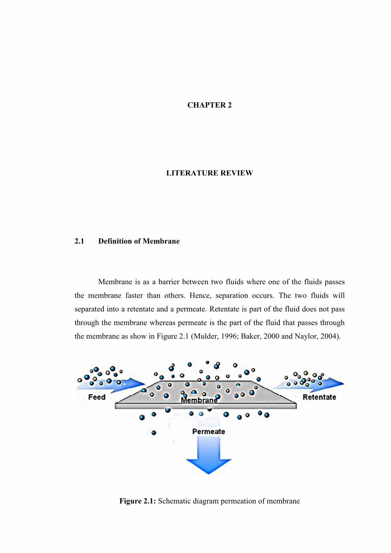
Membrane is as a barrier between two fluids where one of the fluids passes
the membrane faster than others. Hence, separation occurs. The two fluids will
separated into a retentate and a permeate. Retentate is part of the fluid does not pass
through the membrane whereas permeate is the part of the fluid that passes through
the membrane as show in Figure 2.1 (Mulder, 1996; Baker, 2000 and Naylor, 2004).
Figure 2.1: Schematic diagram permeation of membrane

6
2.2 History of Gas Separation
Study of gas separation has a long history but it has become major industrial
application of membrane technology only during the past 20 years (Baker, 2000). On
1866, Thomas Graham gave first description of the solution-diffusion model by
which the penetrant first dissolve in the membrane and then diffused through by the
same process as that occurring in liquids. He demonstrated that atmospheric air could
be enriched from 21 % and 41 % oxygen using a natural rubber membrane. He also
showed that the permeation rate will effect by the thickness where permeation rate of
the gas decrease as the film thickness increase. His work on porous membrane led to
Graham’s law of diffusion (Baker, 2000 and Naylor, 2004).
Gas separation by polymer was observed by Mitchell in 1891 who found
India rubber films permeated CO2 faster than hydrogen (Naylor, 2004). End of
nineteenth and early twentieth century’s, the ability of gas to permeate membrane has
no industrial or commercial use but the concept is used as theoretical tool to develop
physical and chemical theories such as Maxwell’s kinetic theory of gas (Baker,
2000).
From 1943 to 1945, for the first time Graham’s law of diffusion is used for
separation of uranium gas isotopes for uranium enrichment. U235
F6 is separate from
U238
F6. This project is part of Manhattan project (Baker, 2000 and Naylor, 2004).
The separation plant, the first large scale membrane that use for gas separation built
in Knoxville, Tennessee and for the next 40 years become world largest membrane
separation plant (Baker,2000).
In 1940 to 1950, the foundation of modern theories of gas permeation is laid
by Barrer, van Amerongen, Stren, Meares and others academic studies (Baker, 2000
and Naylor, 2004). The previous law, Graham’s law of diffusion is still accepted for
gas transport through membrane. Despite the availability of interesting polymer, to
make useful separation membrane systems from these polymers, membrane
fabrication technology is not sufficiently advance at that time (Baker, 2000).

7
Late 1960, techniques developed to produce high flux anisotropic, large
surface area, thin and defect free polymeric membrane for reverse osmosis and
provided the basis for modern membrane gas separation technology early 1970
(Baker, 2000 and Naylor, 2004). Cellulose acetate for gas dehydration and gas
separation are the first polymer to be commercialized. The problem to commercial
the gas separation membrane is to economically package large area of membrane.
Bray and Westmoreland provided a solution in 1968 the development for reverse
osmosis of the spiral wound module. Led to the large scale introduction of gas
separation process is due to the development of hollow fibres by Dow and DuPont in
between 1968 to 1971. General Electric developed polycarbonate/silicon rubber
copolymer was developed for oxygen enrichment of air (Naylor, 2004).
In 1980, Masanto has led to the recent world wide surge in interest in gas
separation systems by success in commercializing its Prism membrane which
polysulphone with a sealing layer of polydimethylsiloxane for hydrogen sepration
(Baker, 2000 and Naylor, 2004). Membrane plant to remove carbon dioxide from
methane was built in mid 1980 by Cynara, Separex and Gas Membrane Systems.
Although need to face low natural gas price in the 1990, this application grown over
the years. At the same time, Dow launched Generon, the first commercial membrane
system for nitrogen separation from air. Dow, Ube and DuPont develop materials
with improved selectivities since made membrane produce nitrogen was cost
competitive (Baker, 2000).
2.3 Membrane Modules
2.3.1 Plate-and-Frame Modules
Plate-and frame modules are one of the earliest modules of membrane
system. Membrane, feed spacers and product are layered together between two end

8
plates. The feed mixture is forced across the surface of the membrane. A portion
passes through membrane, enters the permeate channel, and makes its way to a
central permeate collection manifold (Baker, 2000 and Naylor, 2004). Figure 2.2
show schematic drawing of plate and frame module.
Figure 2.2: Schematic drawing of plate and frame module
2.3.2 Spiral Wound Modules
The spiral wound modules is the next logical step from flat membrane. It is in
fact a plate-and frame system wrapped around a central collection pipe, in a similar
fashion to a sandwich roll. Membrane and permeate side spacer material are then
glued along three edges to built a membrane envelope. The feed side spacer
separating the top layer of the two flat membranes also acts as a turbulence promoter
(Baker, 2000 and Naylor, 2004). This module is shown schematically in Figure 2.3.

9
Figure 2.3: Schematic drawing of spiral wound module
2.3.3 Hollow Fiber Modules
Hollow fiber membrane modules are formed in two basic geometries. The
first is the shell side feed design illustrated in Figure 2.4. A loop or a closed bundle
of fibers in contained in a pressure vessel. The system is pressurized from the shell
side. Permeate passes through the fiber wall and exits through the open fiber ends.
This design is easy to make and allows very large membrane areas to be contained in
an economical system. Because the fiber wall must support considerable hydrostatic
pressure, the fibers usually have small diameters and thick walls, typically 50 m
internal diameter and 100 to 200 m outer diameter (Baker, 2000 and Naylor, 2004).

10
Figure 2.4: Illustrated design of hollow fiber module, shell side feed
The second type of hollow fiber module is the bore side feed type illustrated
in Figure 2.5. The fibers in this type of unit are open at both ends, and the feed fluid
is circulated through the bore of the fibers. To minimize pressure drop inside the
fibers, the diameter are usually larger than those of the fine fibers used in the shell
side feed system and are generally made by solution spinning. These called capillary
fibers that used in ultrafiltration, pervaporation and some low to medium pressure
gas application. Feed pressures are usually limited to below 150 psig (Baker, 2000
and Naylor, 2004).
11
Figure 2.5: Illustrated design of hollow fiber module bore side feed
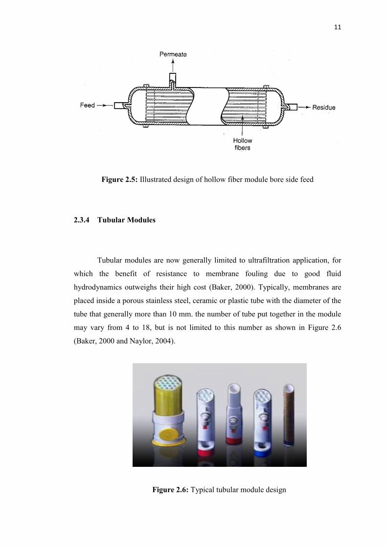
2.3.4 Tubular Modules
Tubular modules are now generally limited to ultrafiltration application, for
which the benefit of resistance to membrane fouling due to good fluid
hydrodynamics outweighs their high cost (Baker, 2000). Typically, membranes are
placed inside a porous stainless steel, ceramic or plastic tube with the diameter of the
tube that generally more than 10 mm. the number of tube put together in the module
may vary from 4 to 18, but is not limited to this number as shown in Figure 2.6
(Baker, 2000 and Naylor, 2004).
Figure 2.6: Typical tubular module design

12
2.4 Membrane Materials
2.4.1 Polymeric Membrane
Most gas separation processes require that the selective membrane layer be
extremely thin to achieve economical flux. Typical membrane thicknesses are less
than 0.5 m and often less than 0.1 m. Early gas separation membranes were
adapted from the cellulose acetate membrane for reverse osmosis (Baker, 2000).
Gas separation membranes are sensitive to minor defect shown in Figure 2.7,
such as pinholes in the selective membrane layer, than membranes used in reverse
osmosis or ultrafiltration. Small defect can highly decrease the selectivity of gas
separation membranes. For early developer, the sensitivity of gas separation
membranes to defects becomes a serious problem. Moreover, few defects are very
difficult to avoid during membrane preparation and module formation. So that,
coating is the solution to plugged membrane defect by apply thin layer of coating
agent such as silicon rubber to the membranes (Baker, 2000).
Figure 2.7: Schematic drawing of defect sealing on selective layer