Developing a Visualization Tool for Mobile Software...
5
Developing a Visualization Tool for Mobile Software Testing Keunsang Yi 1 , Hyun Seung Son 1 , R. Young Chul Kim 1* 1 SELab., Dept. of Computer and Information Communication, Hongik University, Sejong, Korea [email protected] Abstract— Android platform applications are developed with two ways: UI design and Source code implementation. How to analyze mobile SW complexity? It is difficult to do with the previous measuring elements of SW complexity such as module, class, and package units. To solve this problem, we suggest to visualize an activity call graph between activities as the basic unit of android platform, and measure the complexity between intents for analysis of code complexity of mobile software. For code visualization, we develop the open source based Tool-Chain like a static analysis tool. By inputting mobile source code into this tool, we can build and analyze an activity call graph. We can see inner code structure through this visualization, which then diagnose to cause some complex code to potentially occur malfunction of android mobile codes. Keywords-Code Visualization; Mobile Based Testing; Complexity; SW Quality; SW Visualization in Nipa‟s Software engineering Center; I. INTRODUCTION In these days, mobile SW is required to be developed for works on various mobile platforms with original functions which are developed in the existing development environment. These mobile SW need highly advanced and efficient resources. Especially poor optimization of advanced smart devices may make it difficult to develop mobile SW. The more code complexity becomes increased, the worse it leads to an increase in SW defects of devices. Android mobile applications are developed with both UI code and the core code apart. For a static analysis, our Tool-Chain also visualizes source code based on the existing SW visualization [1-2]. But it‟s impossible to visualize mobile SW code expressing interactions between activities by intent on Android. We reinforce visualization for the internal code structure of mobile application SW through intent between android activities. With this visualized structure, we diagnose the causes of Bad-smell structure for refactoring, and finally suggest an automatic static analysis for mobile application SW. Therefore, it is organized as follows: Chapter 2 describes mobile application testing technique as related research, Chapter 3 shows automatic static analysis mechanism, and Chapter 4 mentions our enhanced Tool-Chain for a static analysis of mobile application code. Chapter 5 describes conclusion. II. RELATED RESEARCH 2.1 Mobile Applications Testing Technique Since mobile applications work in various platform environments, mobile application testing is different from the existing SW testing. To meet requirements of mobile application testing, it carries out testing activities and objectives like functional and behavior testing, interoperability testing, usability testing, and so on. In order to test mobile SW accurately, each application on various platform devices would run. However, testing all the devices would take great expense. Mobile application testing includes Emulation-based Testing, Device-based Testing, Cloud Testing and Crowd-based Testing [3]. 2.1.1 Emulation based Testing Figure 1. Emulation-based testing Emulation based testing carries out tests actual device environments using a virtual environment emulator. With emulation based testing as shown in Figure 1, it is difficult to test behavior that occurs in an application due to a difference in memory and speed from actual device. 2.1.2 Device-based Testing Figure 2 shows a device based testing structure. It has virtues in that it can test all scenarios using an actual device. It can also grasp problems on an actual device which cannot be measured in an emulation based test. Figure 2. Device-based testing International Journal of Applied Engineering Research, ISSN 0973-4562 Vol. 10 No.90 (2015) © Research India Publications; http/www.ripublication.com/ijaer.htm 287
-
Upload
duonghuong -
Category
Documents
-
view
221 -
download
3
Transcript of Developing a Visualization Tool for Mobile Software...
Developing a Visualization Tool for Mobile
Software Testing
Keunsang Yi1, Hyun Seung Son
1, R. Young Chul Kim
1*
1 SELab., Dept. of Computer and Information Communication, Hongik University, Sejong, Korea
Abstract— Android platform applications are developed with two ways: UI design and Source code implementation. How to analyze mobile SW complexity? It is difficult to do with the previous measuring elements of SW complexity such as module, class, and package units. To solve this problem, we suggest to visualize an activity call graph between activities as the basic unit of android platform, and measure the complexity between intents for analysis of
code complexity of mobile software. For code visualization, we develop the open source based Tool-Chain like a static analysis tool. By inputting mobile source code into this tool, we can build and analyze an activity call graph. We can see inner code structure through this visualization, which then diagnose to cause some complex code to potentially occur malfunction of android mobile codes.
Keywords-Code Visualization; Mobile Based Testing; Complexity;
SW Quality; SW Visualization in Nipa‟s Software engineering Center;
I. INTRODUCTION
In these days, mobile SW is required to be developed for
works on various mobile platforms with original functions which are developed in the existing development environment. These mobile SW need highly advanced and efficient resources. Especially poor optimization of advanced smart devices may make it difficult to develop mobile SW. The more code complexity becomes increased, the worse it leads to an increase in SW defects of devices.
Android mobile applications are developed with both UI code and the core code apart. For a static analysis, our Tool-Chain also visualizes source code based on the existing SW visualization [1-2]. But it‟s impossible to visualize mobile SW code expressing interactions between activities by intent on Android. We reinforce visualization for the internal code structure of mobile application SW through intent between android activities. With this visualized structure, we diagnose the causes of Bad-smell structure for refactoring, and finally suggest an automatic static analysis for mobile application SW.
Therefore, it is organized as follows: Chapter 2 describes mobile application testing technique as related research, Chapter 3 shows automatic static analysis mechanism, and Chapter 4 mentions our enhanced Tool-Chain for a static analysis of mobile application code. Chapter 5 describes conclusion.
II. RELATED RESEARCH
2.1 Mobile Applications Testing Technique
Since mobile applications work in various platform environments, mobile application testing is different from the existing SW testing. To meet requirements of mobile application testing, it carries out testing activities and objectives like functional and behavior testing, interoperability testing, usability testing, and so on. In order to test mobile SW accurately, each application on various platform devices would run. However, testing all the devices would take great expense. Mobile application testing includes Emulation-based Testing, Device-based Testing, Cloud Testing and Crowd-based Testing [3].
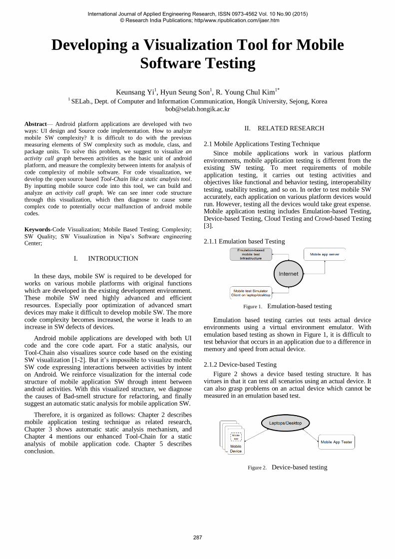
2.1.1 Emulation based Testing
Figure 1. Emulation-based testing
Emulation based testing carries out tests actual device environments using a virtual environment emulator. With emulation based testing as shown in Figure 1, it is difficult to test behavior that occurs in an application due to a difference in memory and speed from actual device.
2.1.2 Device-based Testing
Figure 2 shows a device based testing structure. It has virtues in that it can test all scenarios using an actual device. It can also grasp problems on an actual device which cannot be measured in an emulation based test.
Figure 2. Device-based testing
International Journal of Applied Engineering Research, ISSN 0973-4562 Vol. 10 No.90 (2015) © Research India Publications; http/www.ripublication.com/ijaer.htm
287

However, a device-based testing technique requires great expenses in comparison to other testing methods due to purchase of an actual device. Although mobile service companies purchase a mobile device for testing, it has difficulties in terms of test quality and efficiency.
2.1.3 Cloud-based Testing
Cloud based testing implements existing testing techniques in cloud service environment. Currently, the cloud based mobile test supporting tool is Keynote, Although there is a demand for testing cloud based mobile applications and services, development and support for it are in short supply.
2.1.4 Crowd-based Testing
Figure 3 shows an implementation of testing multiple clients that possess a broad range of mobile devices of various types for cloud testing.
Figure 3. Crowd-based Testing
Cloud testing can reduce cost required for developing mobiles. Especially, as it can discover errors of mobile applications in a short period of time, it is utilized by such companies as eBay, Amazon, GE, Microsoft, Google, and Facebook. However, with diverse App testing techniques that we have examined thus far, a large-scale testing is difficult since there is a shortage of automated infrastructure for integrated testing among heterogeneous platforms. Especially, we are in need of standardization of script solutions that can provide support for integration and interoperability among mobile applications testing tools.
2.2 Software Visualization
In order to develop good software, it is essential to manage the process of software development and implement tests. In this, mobile applications development is no exception. Furthermore, quality of software can be enhanced through such engineering certification of software as SP (Software Process) and GS (Good Software) of Korea, CMMI (Capability Maturity Model Integration) from abroad, or TMMI (Test Maturity Model Integration) which is based on CMMI.
However, due to difficulty involved in manpower and cost, 1-person companies of mobile software, venture companies, and SMBs are pursuing coding-oriented development rather than engineering-oriented quality control. To detect and manage SW changes in temporal perspective, Christian Collberg [4] used control-flow graphs, call graphs, and inheritance graphs. However, it is difficult to grasp information on diverse changes at once using this approach due to shortage of visual function. Michele Lanza [5] tested SW using diverse metrics (class, special feature). Although possible to see
diverse information on each element, this approach does not allow a bird‟s eye view of program flow and SW architecture.
In order to solve these problems, an effort was made in this research to present a visualization of object-oriented SW structure and related processes through SW visualization and to study procedures for quality improvement of coupling based software [6]. Reverse Engineering technique is used to grasp the structure of SW that have been developed already through separation of code-oriented development process and to discern interrelationship among software components (modules), which allows a higher level representation [7].
2.3 Construction of Tool-Chain for statically analyzing Mobile
software applications
Static analysis of mobile applications consists of three stages such that 1) at the first stage, program sources are analyzed (using a parser or analyzer), at the second stage the analyzed information are transformed into a database, and at the third stage with information contained in DB, a structural analysis is carried out and visualized inner code structure. We do then refactoring to reduce complexity with quality metrics implemented on visualization [8]. Figure 4 shows the Tool-Chain mechanism.
Figure 4. The previous Tool-Chain mechanism
For parsing or analysis, Source Navigator (SN) [9] is used, and the tool chain is included to link DOT script and SQLite [10].
Step 1: The code of a mobile App is analyzed using SN. General information on App source code such as class, inheritance relationship, local variable, global variable, and parameter are extracted.
Step 2: SN DB files which are extracted in binary format in Step 1 are converted to texts stored in SQLite DB, and are stored in each table of the database.
Step 3: The association relationships with module units are defined, and each level of couplings is recognized as extracting with queries for quantitative metric scoring.
International Journal of Applied Engineering Research, ISSN 0973-4562 Vol. 10 No.90 (2015) © Research India Publications; http/www.ripublication.com/ijaer.htm
288
Step 4: Based on defining the quality metrics it is created DOT script with extracted information with queries. Then a graph is visualized with DOT script on DOT tool.
III. AUTOMATIC STATIC ANALYSIS MECHANISM
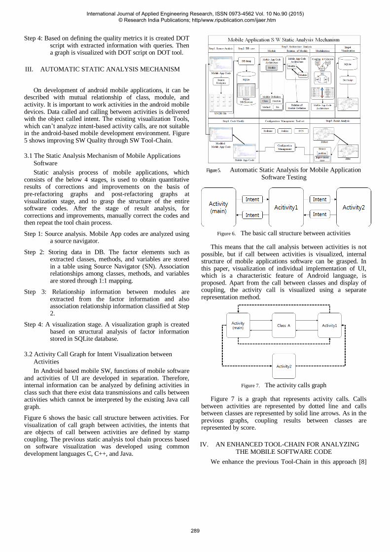
On development of android mobile applications, it can be described with mutual relationship of class, module, and activity. It is important to work activities in the android mobile devices. Data called and calling between activities is delivered with the object called intent. The existing visualization Tools, which can‟t analyze intent-based activity calls, are not suitable in the android-based mobile development environment. Figure 5 shows improving SW Quality through SW Tool-Chain.
3.1 The Static Analysis Mechanism of Mobile Applications
Software
Static analysis process of mobile applications, which consists of the below 4 stages, is used to obtain quantitative results of corrections and improvements on the basis of pre-refactoring graphs and post-refactoring graphs at visualization stage, and to grasp the structure of the entire software codes. After the stage of result analysis, for corrections and improvements, manually correct the codes and then repeat the tool chain process.
Step 1: Source analysis. Mobile App codes are analyzed using a source navigator.
Step 2: Storing data in DB. The factor elements such as extracted classes, methods, and variables are stored in a table using Source Navigator (SN). Association relationships among classes, methods, and variables are stored through 1:1 mapping.
Step 3: Relationship information between modules are extracted from the factor information and also association relationship information classified at Step 2.
Step 4: A visualization stage. A visualization graph is created based on structural analysis of factor information stored in SQLite database.
3.2 Activity Call Graph for Intent Visualization between
Activities
In Android based mobile SW, functions of mobile software and activities of UI are developed in separation. Therefore, internal information can be analyzed by defining activities in class such that there exist data transmissions and calls between activities which cannot be interpreted by the existing Java call graph.
Figure 6 shows the basic call structure between activities. For visualization of call graph between activities, the intents that are objects of call between activities are defined by stamp coupling. The previous static analysis tool chain process based on software visualization was developed using common development languages C, C++, and Java.
Figure 5. Automatic Static Analysis for Mobile Application Software Testing
Figure 6. The basic call structure between activities
This means that the call analysis between activities is not possible, but if call between activities is visualized, internal structure of mobile applications software can be grasped. In this paper, visualization of individual implementation of UI, which is a characteristic feature of Android language, is proposed. Apart from the call between classes and display of coupling, the activity call is visualized using a separate representation method.
Figure 7. The activity calls graph
Figure 7 is a graph that represents activity calls. Calls between activities are represented by dotted line and calls between classes are represented by solid line arrows. As in the previous graphs, coupling results between classes are represented by score.
IV. AN ENHANCED TOOL-CHAIN FOR ANALYZING THE MOBILE SOFTWARE CODE
We enhance the previous Tool-Chain in this approach [8]
International Journal of Applied Engineering Research, ISSN 0973-4562 Vol. 10 No.90 (2015) © Research India Publications; http/www.ripublication.com/ijaer.htm
289
such as Parser (Source Navigator (SN) 6.0), Database (SQLite), and View Composer (DOT). We used the Use Case Diagram Drawing Tool based on JAVA.
4.1 Analysis of SN DB FILE Schema
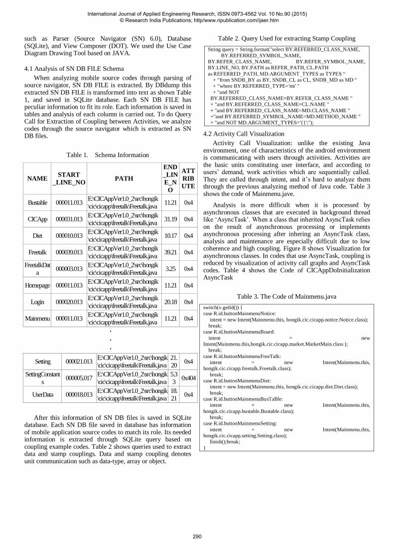
When analyzing mobile source codes through parsing of source navigator, SN DB FILE is extracted. By DBdump this extracted SN DB FILE is transformed into text as shown Table 1, and saved in SQLite database. Each SN DB FILE has peculiar information to fit its role. Each information is saved in tables and analysis of each column is carried out. To do Query Call for Extraction of Coupling between Activities, we analyze codes through the source navigator which is extracted as SN DB files.
Table 1. Schema Information
NAME START
_LINE_NO PATH
END
_LIN
E_N
O
ATT
RIB
UTE
Bustable 000011.013 E:\CICAppVer1.0_2\src\hongik
\cic\cicapp\freetalk\Freetalk.java 11.21 0x4
CICApp 000031.013 E:\CICAppVer1.0_2\src\hongik
\cic\cicapp\freetalk\Freetalk.java 31.19 0x4
Diet 000010.013 E:\CICAppVer1.0_2\src\hongik
\cic\cicapp\freetalk\Freetalk.java 10.17 0x4
Freetalk 000039.013 E:\CICAppVer1.0_2\src\hongik
\cic\cicapp\freetalk\Freetalk.java 39.21 0x4
FreetalkDat
a 000003.013
E:\CICAppVer1.0_2\src\hongik
\cic\cicapp\freetalk\Freetalk.java 3.25 0x4
Homepage 000011.013 E:\CICAppVer1.0_2\src\hongik
\cic\cicapp\freetalk\Freetalk.java 11.21 0x4
Login 000020.013 E:\CICAppVer1.0_2\src\hongik
\cic\cicapp\freetalk\Freetalk.java 20.18 0x4
Mainmenu 000011.013 E:\CICAppVer1.0_2\src\hongik
\cic\cicapp\freetalk\Freetalk.java 11.21 0x4
∙
∙
∙
Setting 000021.013 E:\CICAppVer1.0_2\src\hongik
\cic\cicapp\freetalk\Freetalk.java
21.
20 0x4
SettingConstant
s 000005.017
E:\CICAppVer1.0_2\src\hongik
\cic\cicapp\freetalk\Freetalk.java
5.3
3 0x404
UserData 000018.013 E:\CICAppVer1.0_2\src\hongik
\cic\cicapp\freetalk\Freetalk.java
18.
21 0x4
After this information of SN DB files is saved in SQLite database. Each SN DB file saved in database has information of mobile application source codes to match its role. Its needed information is extracted through SQLite query based on coupling example codes. Table 2 shows queries used to extract data and stamp couplings. Data and stamp coupling denotes unit communication such as data-type, array or object.
Table 2. Query Used for extracting Stamp Coupling
String query = String.format("select BY.REFERRED_CLASS_NAME,
BY.REFERRED_SYMBOL_NAME,
BY.REFER_CLASS_NAME, BY.REFER_SYMBOL_NAME,
BY.LINE_NO, BY.PATH as REFER_PATH, CL.PATH
as REFERRED_PATH, MD.ARGUMENT_TYPES as TYPES “
+ "from SNDB_BY as BY, SNDB_CL as CL, SNDB_MD as MD “
+ "where BY.REFERRED_TYPE='mi' "
+ "and NOT
BY.REFERRED_CLASS_NAME=BY.REFER_CLASS_NAME "
+ "and BY.REFERRED_CLASS_NAME=CL.NAME "
+ "and BY.REFERRED_CLASS_NAME=MD.CLASS_NAME "
+"and BY.REFERRED_SYMBOL_NAME=MD.METHOD_NAME "
+ "and NOT MD.ARGUMENT_TYPES='{}';");
4.2 Activity Call Visualization
Activity Call Visualization: unlike the existing Java environment, one of characteristics of the android environment is communicating with users through activities. Activities are the basic units constituting user interface, and according to users‟ demand, work activities which are sequentially called. They are called through intent, and it‟s hard to analyze them through the previous analyzing method of Java code. Table 3 shows the code of Mainmenu.jave.
Analysis is more difficult when it is processed by asynchronous classes that are executed in background thread like „AsyncTask‟. When a class that inherited AsyncTask relies on the result of asynchronous processing or implements asynchronous processing after inhering an AsyncTask class, analysis and maintenance are especially difficult due to low coherence and high coupling. Figure 8 shows Visualization for asynchronous classes. In codes that use AsyncTask, coupling is reduced by visualization of activity call graphs and AsyncTask codes. Table 4 shows the Code of CICAppDoInitialization AsyncTask
Table 3. The Code of Mainmenu.java
switch(v.getId()) {
case R.id.buttonMainmenuNotice:
intent = new Intent(Mainmenu.this, hongik.cic.cicapp.notice.Notice.class);
break;
case R.id.buttonMainmenuBoard:
intent = new
Intent(Mainmenu.this,hongik.cic.cicapp.market.MarketMain.class );
break;
case R.id.buttonMainmenuFreeTalk:
intent = new Intent(Mainmenu.this,
hongik.cic.cicapp.freetalk.Freetalk.class);
break;
case R.id.buttonMainmenuDiet:
intent = new Intent(Mainmenu.this, hongik.cic.cicapp.diet.Diet.class);
break;
case R.id.buttonMainmenuBusTaBle:
intent = new Intent(Mainmenu.this,
hongik.cic.cicapp.bustable.Bustable.class);
break;
case R.id.buttonMainmenuSetting:
intent = new Intent(Mainmenu.this,
hongik.cic.cicapp.setting.Setting.class);
finish();break;
}
International Journal of Applied Engineering Research, ISSN 0973-4562 Vol. 10 No.90 (2015) © Research India Publications; http/www.ripublication.com/ijaer.htm
290

Table 4. The Code of CICAppDoInitialization AsyncTask
V. CONCLUSION AND FUTURE RESEARCH
This study suggests building up automatic static analysis
mechanism for mobile application SW testing, and methods to
reduce defects of mobile application SW through visualizing
activity call graph. A static analysis oriented Tool-Chain
process is suggested, and it can work quality control and
visualization enhanced by the previous static analysis of SW
code.
Figure 8: Visualization for asynchronous classes with
dotted hexagon
Android codes are divided into internal function and UI. When
the existing Tool-Chain process analyzes android mobile application SW, it is important to call and transfer data between
activities as the basic unit of android UI that can‟t be analyzed
and visualized. We suggest setting up the static analysis
mechanism, and an activity call graph of android mobile SW
application. This reduced coupling of mobile application SW,
and removed unnecessary calls and data transmission by
visualizing calls between activities. For future study, we are
still keeping activity-related UI design, and reducing McCabe‟s
cyclomatic complexity of coupling & cohesion.
ACKNOWLEDGMENT This work was supported by 2014 Hongik University Research Fund and Basic
Science Research Program through the National Research Foundation of Korea
(NRF) funded by the Ministry of Education (NRF-2013R1A1A2011601).
REFERENCES [1] Park, B.K., Kwon, H.E., Yang, H.S., Moon, S.Y., Kim, Y.S. and Kim, R.
Y.C., 2014, “A Study on Tool-Chain for statically analyzing Object
Oriented Code,” Proc. of Korea Computer Congress 2014, pp. 463-465.
[2] National IT Industry Promotion Agency (NIPA), http://www.nipa.kr
[3] Gao, J., Bai, X., Tsai, W. T. and Uehara, T., 2014, “Mobile Application
Testing: A Tutorial,” Computer, 47(2), pp. 46-55.
[4] Collberg, C., Kobourov, S., Nagra, J., Pitts, J. and Wampler, K., 2003,
“A System for Graph-Based Visualization of the Evolution of
Software,” Proc. of The SoftVis '03 ACM symposium on Software
visualization, pp. 77-86.
[5] Lanza, M., 2001, “The Evolution Matrix: Recovering Software
Evolution using Software Visualization Techniques,” Proc. of The
IWPSE '01, pp. 37-42.
[6] Kang, G.H., Yi, K.S., Kim, D.H., Hwang, J.S., Kim, Y.S., Park, Y.B.
and Kim, R. Y.C., 2014, “A Practical Study on Tool Chain for Code
Static Analysis on Procedural Language,” Proc. of Korea Computer
Congress 2014, pp. 559-561.
[7] Kwon, H.E., Park, B.K., Yi, K.S., Park, Y.B., Kim, Y.S and Kim, R.
Y.C., 2014, “Applying Reverse Engineering through extracting Models
from Code Visualization,” The 2014 Fall Conference of the KIPS, 21(2),
pp. 650-653.
[8] Kang, G.H., Kim, R. Y.C., Yi, K.S., Kim, Y.S., Park, Y.B. and Son,
H.S., 2015, “A Practical Study on Code Static Analysis through Open
Source based Tool Chains,” KIISE Transactions on Computing Practices,
21(2), pp. 148-153.
[9] SN group, Source Navigator User Guide [Online], Available:
http://sourcenav.sourceforge.net/
[10] SQLite, About SQLite [Online], Available: https://www.sqlite.org
class DoInitialization extends AsyncTask<Void, String, Void> {
protected void onPreExecute() { super.onPreExecute(); } protected Void doInBackground(Void... arg0) {
try { URL url = new URL("http://cic.hongik.ac.kr/_android/freetalk_select.php"); HttpURLConnection conn = (HttpURLConnection) url.openConnection(); . . . //Send to Server StringBuffer buffer = new StringBuffer(); . . . //XmlPullParser Instance Object Creat for Recive Talk List . . . //XmlPullParsing Start . . .; String tag; FreetalkData data = new FreetalkData(); while((parserEvent = xpp.next()) != XmlPullParser.END_DOCUMENT) {
switch(parserEvent) { case XmlPullParser.START_TAG:
.. case XmlPullParser.END_TAG: . . . f(inTitle2) {
data.setText(xpp.getText()); . . . if(data.getId().equals(user.getId(
))) { publishProgress(null,
data.getText(), null, "0"); } else {
publishProgress(data.getId(),data.getText(),data.getName(),"1");
} } break;
} } conn.disconnect();
} catch (IOException e) { e.printStackTrace();} catch (XmlPullParserException e) {
e.printStackTrace(); } return null; }
}
International Journal of Applied Engineering Research, ISSN 0973-4562 Vol. 10 No.90 (2015) © Research India Publications; http/www.ripublication.com/ijaer.htm
291