
Determination of dynamic stress in fibre reinforced ...
7
267 Determination of dynamic stress in fibre reinforced materials under impact load D.H. Müller, Th. Franz and A. Tenzler Bremer Institut für Konstruktionstechnik (BIK), University of Bremen, 28359 Bremen, Germany Tel.: +49 421 2184262; Fax: +49 421 2184263; E-mail: [email protected] Received 5 December 1995 Revised 27 July 1998 The investigations reported in this paper are intended to ob- tain knowledge about stress concentrations within fibre re- inforced plastics due to impact loadings below the damage threshold of the anisotropic material. The paper focuses on presenting the application of a dynamic photoelastic tech- nique more than on providing extensive and detailed experi- mental data. Thus, a brief summary of the experimental part is given. The potential value of the developed experimental method is demonstrated exemplary for an arbitrary compos- ite. 1. Introduction The mechanical properties and the behaviour of fibre-reinforced plastic (FRP) have been studied espe- cially for static loading of machine parts. The prob- lem of determining the distribution of stresses and/or strains in a two-dimensional FRP-specimen subjected to an impact type of loading is difficult to solve mathe- matically. Therefore, experimental means are essential and, sometimes, indispensable. Fibre-reinforced com- posites are mainly used when high accelerations and velocities take place. Then, composites offer a high po- tential to reduce the kinetic energy. As a consequence, these parts very often have a high impact endanger- ing. The reinforcement of the composites is a major pa- rameter to reduce the material stress not only for static loadings but also when impact loadings take place. In the case of an impact loading, the viscoelasticity of the plastic matrix has to be considered. The photoelastic- ity offers an appropriate method for the investigation of impact stresses in reinforced materials, especially for stress concentrations due to complex shapes like notches or holes. 2. Experimental impact simulation There are big differences regarding the stresses be- tween static, quasi-static and impact loading. An im- pact is effected when the contact time is short com- pared to the time of wave pass through the part or spec- imen. If an impact loading is subjected to a structure, it is accelerated with the consequence that inertia forces are produced. Therefore, there is no linearity between the impact force and the stresses. The experimental simulation of an impact requires the control of three characteristics: impact force F (t), contact time and impulse. Within the loading device (Fig. 1), the impact is created by a steel projectile pneu- matically accelerated in a pipe. The projectile veloc- ity can be changed by altering the pneumatic pres- sure. A typical impact force history of the loadings ap- plied during the experiments reported here is shown in Fig. 2. The contact time of about 10 to 20 μs is reason- able short to generate impact waves. Fig. 1. Loading device. Shock and Vibration 5 (1998) 267–272 ISSN 1070-9622 / $8.00 1998, IOS Press. All rights reserved
Transcript of Determination of dynamic stress in fibre reinforced ...
267
Determination of dynamic stress in fibrereinforced materials under impact load
D.H. Müller, Th. Franz and A. TenzlerBremer Institut für Konstruktionstechnik (BIK),University of Bremen, 28359 Bremen, GermanyTel.: +49 421 2184262; Fax: +49 421 2184263;E-mail: [email protected]
Received 5 December 1995
Revised 27 July 1998
The investigations reported in this paper are intended to ob-tain knowledge about stress concentrations within fibre re-inforced plastics due to impact loadings below the damagethreshold of the anisotropic material. The paper focuses onpresenting the application of a dynamic photoelastic tech-nique more than on providing extensive and detailed experi-mental data. Thus, a brief summary of the experimental partis given. The potential value of the developed experimentalmethod is demonstrated exemplary for an arbitrary compos-ite.
1. Introduction
The mechanical properties and the behaviour offibre-reinforced plastic (FRP) have been studied espe-cially for static loading of machine parts. The prob-lem of determining the distribution of stresses and/orstrains in a two-dimensional FRP-specimen subjectedto an impact type of loading is difficult to solve mathe-matically. Therefore, experimental means are essentialand, sometimes, indispensable. Fibre-reinforced com-posites are mainly used when high accelerations andvelocities take place. Then, composites offer a high po-tential to reduce the kinetic energy. As a consequence,these parts very often have a high impact endanger-ing. The reinforcement of the composites is a major pa-rameter to reduce the material stress not only for staticloadings but also when impact loadings take place. Inthe case of an impact loading, the viscoelasticity of theplastic matrix has to be considered. The photoelastic-ity offers an appropriate method for the investigationof impact stresses in reinforced materials, especiallyfor stress concentrations due to complex shapes likenotches or holes.
2. Experimental impact simulation
There are big differences regarding the stresses be-tween static, quasi-static and impact loading. An im-pact is effected when the contact time is short com-pared to the time of wave pass through the part or spec-imen. If an impact loading is subjected to a structure, itis accelerated with the consequence that inertia forcesare produced. Therefore, there is no linearity betweenthe impact force and the stresses.
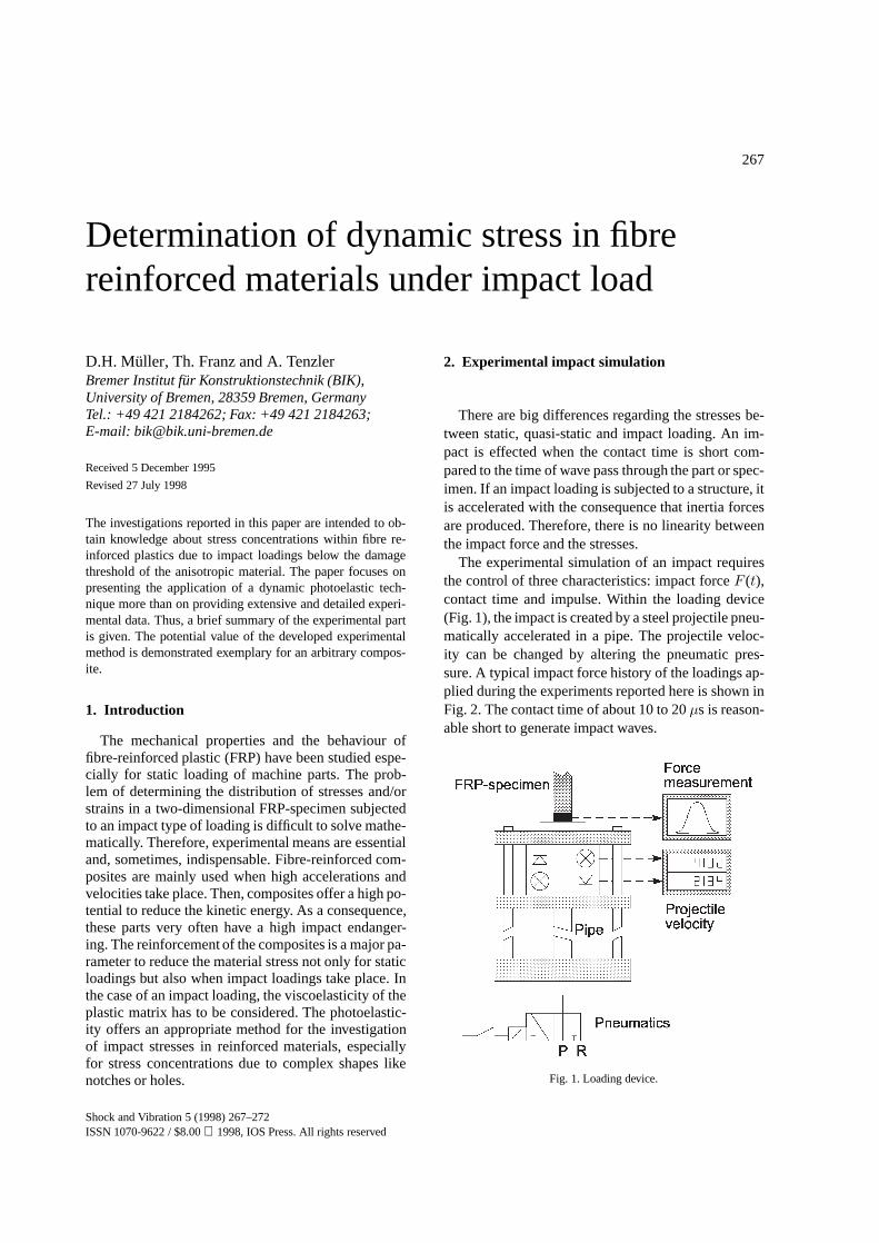
The experimental simulation of an impact requiresthe control of three characteristics: impact forceF (t),contact time and impulse. Within the loading device(Fig. 1), the impact is created by a steel projectile pneu-matically accelerated in a pipe. The projectile veloc-ity can be changed by altering the pneumatic pres-sure. A typical impact force history of the loadings ap-plied during the experiments reported here is shown inFig. 2. The contact time of about 10 to 20µs is reason-able short to generate impact waves.
Fig. 1. Loading device.
Shock and Vibration 5 (1998) 267–272ISSN 1070-9622 / $8.00 1998, IOS Press. All rights reserved

268 D.H. Müller et al. / Determination of dynamic stress in fibre reinforced materials under impact load
Fig. 2. Impact force history.
3. Experimental analysis of stress concentration
The stress analysis along a notch or hole contourrequires a whole-field stress analysis method. In ad-dition, the investigation of wave propagation due toimpact loadings requires a technique with high timeresolution. Therefore, the photoelastic stress coatingmethod is employed in a single-flash operation mode.The experimental set-up derived from the reflectionpolariscope is depicted in Fig. 3. The exposure time isfixed to 500 ns by the Xenon flash-lights. Using a re-tarder, the delay of the shot time after the impact load-ing can be chosen independently in steps of 1µs. Thereproducibility of both the loading and the optical set-up was proved in preliminary tests. The experimentaltechnique has been described detailed elsewhere [3].
The unidirectional reinforcement was used as astandard [2] for the determination of material char-acteristics. The material investigated were unidirec-tional glass-fibre reinforced epoxy resin (GRP). Be-cause of the fibre reinforcement, it is not possible to usethe photoelastic effect of a birefringent matrix resin.Thus, a photoelastic coating is bonded to the com-posite with a reflecting cement. The specimens were200 mm× 200 mm× 3 mm with an centric circu-lar opening of 16 mm. The stress coating were PS-1B(Measurements Group), 1.96 mm, thick with a fringeconstantf = 980µε/fringe. The specimen geometry isshown in Fig. 4.
The strains of the specimen are transmitted via thebonded surface to the photoelastic coating. When thecircularly polarised light passes the coating, it is re-flected by the cement or reflecting backing of the coat-ing, and passes the coating a second time. The isochro-
Fig. 3. Experimental set-up.
Fig. 4. FRP-specimen.
matic fringes increase linearly with the deformationof the specimen. The fringe pattern is recorded witha CCD-video camera. The image information of thecoloured isochromatic fringes is transferred to a framecapture board of a computer. The fringe order along thenotch edge can be automatically calculated using a dig-ital image processing developed to specify the isochro-matic order using the fringe colours [4].
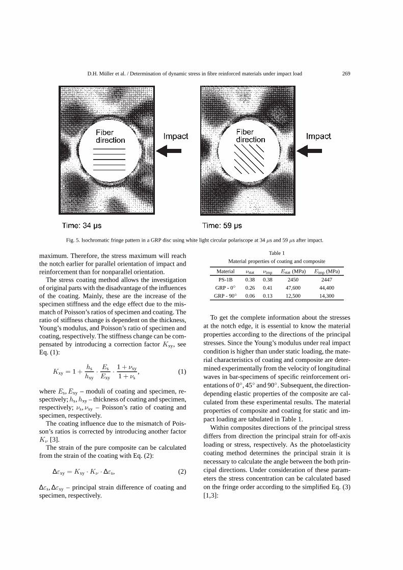
Figure 5 shows the isochromatic fringe patterns ofthe notch area of two specimens. The left image wasrecorded 34µs after the impact from a specimen withfibre reinforcement parallel with the impact direction.The right image was recorded 59µs after the impactfrom a specimen with a reinforcement orientation of45◦ to the impact direction.
If the reinforcement and the impact direction arecongruent the Young’s modulus in impact directionand the propagation velocity of the impact wave are
D.H. Müller et al. / Determination of dynamic stress in fibre reinforced materials under impact load 269
Fig. 5. Isochromatic fringe pattern in a GRP disc using white light circular polariscope at 34µs and 59µs after impact.
maximum. Therefore, the stress maximum will reachthe notch earlier for parallel orientation of impact andreinforcement than for nonparallel orientation.
The stress coating method allows the investigationof original parts with the disadvantage of the influencesof the coating. Mainly, these are the increase of thespecimen stiffness and the edge effect due to the mis-match of Poisson’s ratios of specimen and coating. Theratio of stiffness change is dependent on the thickness,Young’s modulus, and Poisson’s ratio of specimen andcoating, respectively. The stiffness change can be com-pensated by introducing a correction factorKxy, seeEq. (1):
Kxy = 1 +hs
hxy· Es
Exy· 1 + νxy
1 + νs, (1)
whereEs,Exy – moduli of coating and specimen, re-spectively;hs,hxy – thickness of coating and specimen,respectively;νs,νxy – Poisson’s ratio of coating andspecimen, respectively.
The coating influence due to the mismatch of Pois-son’s ratios is corrected by introducing another factorKν [3].
The strain of the pure composite can be calculatedfrom the strain of the coating with Eq. (2):
∆εxy = Kxy ·Kν · ∆εs, (2)
∆εs, ∆εxy – principal strain difference of coating andspecimen, respectively.
Table 1
Material properties of coating and composite
Material νstat νimp Estat (MPa) Eimp (MPa)
PS-1B 0.38 0.38 2450 2447
GRP - 0◦ 0.26 0.41 47,600 44,400
GRP - 90◦ 0.06 0.13 12,500 14,300
To get the complete information about the stressesat the notch edge, it is essential to know the materialproperties according to the directions of the principalstresses. Since the Young’s modulus under real impactcondition is higher than under static loading, the mate-rial characteristics of coating and composite are deter-mined experimentally from the velocity of longitudinalwaves in bar-specimens of specific reinforcement ori-entations of 0◦, 45◦ and 90◦. Subsequent, the direction-depending elastic properties of the composite are cal-culated from these experimental results. The materialproperties of composite and coating for static and im-pact loading are tabulated in Table 1.
Within composites directions of the principal stressdiffers from direction the principal strain for off-axisloading or stress, respectively. As the photoelasticitycoating method determines the principal strain it isnecessary to calculate the angle between the both prin-cipal directions. Under consideration of these param-eters the stress concentration can be calculated basedon the fringe order according to the simplified Eq. (3)[1,3]:
270 D.H. Müller et al. / Determination of dynamic stress in fibre reinforced materials under impact load
σ1 =Kν ·Kxy · f ·N
(1 + νxy) ·√
(S′11− S′12)2 + S
′216
(3)
with
S′11 =1Exy
, S′12 =νxy
Exy,
S′16 = (cos3 θ · sinθ − sin2 θ · cosθ)
×(
2EL
+2νLT
ET− 1GLT
),
whereσ1 – principal stress at the notch edge,N –fringe order,f – fringe constant of the stress coating,Exy – Young’s modulus in principal stress direction,EL,ET – Young’s modulus in and perpendicular to the
reinforcement direction, respectively,νxy,νLT – Pois-son’s ratio in principal stress and reinforcement direc-tion, respectively,GLT – shear modulus in reinforce-ment direction,θ – angle between reinforcement direc-tion and principal stress direction.
4. Stress along the hole contour
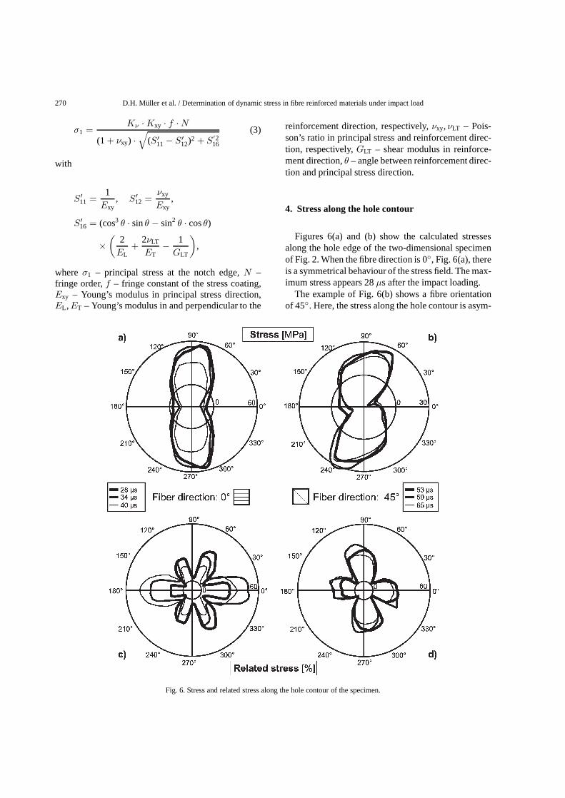
Figures 6(a) and (b) show the calculated stressesalong the hole edge of the two-dimensional specimenof Fig. 2. When the fibre direction is 0◦, Fig. 6(a), thereis a symmetrical behaviour of the stress field. The max-imum stress appears 28µs after the impact loading.
The example of Fig. 6(b) shows a fibre orientationof 45◦. Here, the stress along the hole contour is asym-
Fig. 6. Stress and related stress along the hole contour of the specimen.
D.H. Müller et al. / Determination of dynamic stress in fibre reinforced materials under impact load 271
metrically. The time dependency of the stresses is sim-ilar to that of the fibre direction of 0◦.
Comparing both diagrams it can be stated that thereinforcement direction largely influences the shockwave propagation, especially the maximum propaga-tion velocity and the maximum stress. When the fibrereinforcement is orientated under 45◦ to the impact di-rection the time dependency is much lower.
In dimensioning parts, it has usually to be assuredthat the internal stress does not exceed the strength ofthe material to resist failure. When the used materialis anisotropic the strength depends on the direction.Therefore, the notch stress calculated with Eq. (3) hasto be compared with the direction-depending strengthof the composite.
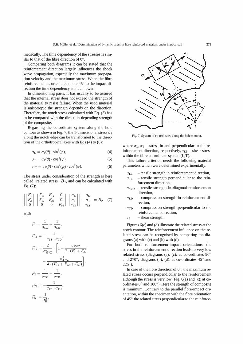
Regarding the co-ordinate system along the holecontour as shown in Fig. 7, the 1-dimensional stressσ1
along the notch edge can be transformed to the direc-tion of the orthotropical axes with Eqs (4) to (6):
σL = σ1(θ) · sin2(ϕ), (4)
σT = σ1(θ) · cos2(ϕ), (5)
τLT = σ1(θ) · sin2(ϕ) · cos2(ϕ). (6)
The stress under consideration of the strength is herecalled “related stress”Bσ, and can be calculated withEq. (7):∣∣∣∣∣∣∣∣∣∣F1
F2
0
∣∣∣∣∣ ·∣∣∣∣∣F11 F12 0F12 F22 00 0 F66
∣∣∣∣∣ ·∣∣∣∣∣ σL
σT
τLT
∣∣∣∣∣∣∣∣∣∣ ·∣∣∣∣∣ σL
σT
τLT
∣∣∣∣∣ = Bσ (7)
with
F1 =1σLZ
+1σLD
,
F11 = − 1σLZ · σLD
,
F12 =2
σ245◦Z
·[1− σ45◦Z
2 · (F1 + F2)
− σ245◦Z
4 · (F11 + F22 + F66)
],
F2 =1σTZ
+1σTD
,
F22 = − 1σTZ · σTD
,
F66 =1τ2
B,
Fig. 7. System of co-ordinates along the hole contour.
whereσL ,σT – stress in and perpendicular to the re-inforcement direction, respectively,τLT – shear stresswithin the fibre co-ordinate system (L,T).
This failure criterion needs the following materialparameters which were determined experimentally:
σLZ – tensile strength in reinforcement direction,σTZ – tensile strength perpendicular to the rein-
forcement direction,σ45◦Z – tensile strength in diagonal reinforcement
direction,σLD – compression strength in reinforcement di-
rection,σTD – compression strength perpendicular to the
reinforcement direction,τB – shear strength.
Figures 6(c) and (d) illustrate the related stress at thenotch contour. The reinforcement influence on the re-lated stress can be recognised by comparing the dia-grams (a) with (c) and (b) with (d).
For both reinforcement-impact orientations, thestress in the reinforcement direction leads to very lowrelated stress (diagrams (a), (c): at co-ordinates 90◦
and 270◦; diagrams (b), (d): at co-ordinates 45◦ and225◦).
In case of the fibre direction of 0◦, the maximum re-lated stress occurs perpendicular to the reinforcementalthough the stress is very low (Fig. 6(a) and (c): at co-ordinates 0◦ and 180◦). Here the strength of compositeis minimum. Contrary to the parallel fibre-impact ori-entation, within the specimen with the fibre orientationof 45◦ the related stress perpendicular to the reinforce-

272 D.H. Müller et al. / Determination of dynamic stress in fibre reinforced materials under impact load
ment is almost minimum (Fig. 6(d): at co-ordinates135◦ and 315◦). Here, the maximum related stress oc-curs under approximate 45◦ to the reinforcement at theco-ordinates 90◦ and 270◦, Fig. 6(d).
5. Conclusions
The experimental method presented here has provedto be good to visualise and analyse wave propaga-tion and stress concentrations within impact loaded fi-bre reinforced composites. Moreover, the results clar-ify the dependence of wave propagation and spatialdistribution of notch stresses on both reinforcement di-rection and time after impact. The investigations ofuni-directional reinforced composite have shown thatthe maximum related stress does not generally occurperpendicular to the reinforcement direction. The di-rection of the maximum related stress varies within arange of 45◦ to the reinforcement direction. Further-
more, the amount of the related stress depends on theorientation of the reinforcement to the impact direc-tion. Therefore, the maximum related stress after animpact loading can be minimised by an adequate fibreorientation.
References
[1] W. Hufenbach, M. Schäfer and A.S. Herrmann, Photoelastis-che Dehnungsmessung und Spannungsverteilung an faserver-stärkten Bauteilen,Kunststoffe, 1991.
[2] K. Moser, Faser-Kunststoff-Verbund, VDI Verlag, Düsseldorf,1992.
[3] A. Tenzler, Entwicklung einer Methode zur Ermittlung vonKerbwirkungen an impactbeanspruchten Faserverbundwerk-stoffen, VDI Verlag, Düsseldorf, 1994.
[4] A. Tenzler and D.H. Müller, Rechnergestütztes Verfahren zurBestimmung farbiger Isochromatenordnungen in der Span-nungsoptik,Vision & Voice Magazine7(1) (1993), 34–39.

International Journal of
AerospaceEngineeringHindawi Publishing Corporationhttp://www.hindawi.com Volume 2010
RoboticsJournal of
Hindawi Publishing Corporationhttp://www.hindawi.com Volume 2014
Hindawi Publishing Corporationhttp://www.hindawi.com Volume 2014
Active and Passive Electronic Components
Control Scienceand Engineering
Journal of
Hindawi Publishing Corporationhttp://www.hindawi.com Volume 2014
International Journal of
RotatingMachinery
Hindawi Publishing Corporationhttp://www.hindawi.com Volume 2014
Hindawi Publishing Corporation http://www.hindawi.com
Journal ofEngineeringVolume 2014
Submit your manuscripts athttp://www.hindawi.com
VLSI Design
Hindawi Publishing Corporationhttp://www.hindawi.com Volume 2014
Hindawi Publishing Corporationhttp://www.hindawi.com Volume 2014
Shock and Vibration
Hindawi Publishing Corporationhttp://www.hindawi.com Volume 2014
Civil EngineeringAdvances in
Acoustics and VibrationAdvances in
Hindawi Publishing Corporationhttp://www.hindawi.com Volume 2014
Hindawi Publishing Corporationhttp://www.hindawi.com Volume 2014
Electrical and Computer Engineering
Journal of
Advances inOptoElectronics
Hindawi Publishing Corporation http://www.hindawi.com
Volume 2014
The Scientific World JournalHindawi Publishing Corporation http://www.hindawi.com Volume 2014
SensorsJournal of
Hindawi Publishing Corporationhttp://www.hindawi.com Volume 2014
Modelling & Simulation in EngineeringHindawi Publishing Corporation http://www.hindawi.com Volume 2014
Hindawi Publishing Corporationhttp://www.hindawi.com Volume 2014
Chemical EngineeringInternational Journal of Antennas and
Propagation
International Journal of
Hindawi Publishing Corporationhttp://www.hindawi.com Volume 2014
Hindawi Publishing Corporationhttp://www.hindawi.com Volume 2014
Navigation and Observation
International Journal of
Hindawi Publishing Corporationhttp://www.hindawi.com Volume 2014
DistributedSensor Networks
International Journal of