CAE Support to the Designn of Parts made ofn of Parts made ...
Upload
ivan-fanelliCategory
view
228download
0
8/3/2019 Designn and Performance of a Innovative Electrically Driven Charging System
http://slidepdf.com/reader/full/designn-and-performance-of-a-innovative-electrically-driven-charging-system 1/20
Dr. S. Münz1, Dr. M. Schier 2, H. P.Schmalzl1, Dr. Th. Bertolini2
eBooster
Design and performance of ainnovative electrically drivencharging system
1 BorgWarner Turbo Systems GmbHMarnheimer Straße 85/87
Academy
67292 Kirchheimbolanden2 ebm Werke GmbH & Co.KG
Bachmühle 274671 Mulfingen
eBooster
Design and performance of a innovative electrically driven
charging system
8/3/2019 Designn and Performance of a Innovative Electrically Driven Charging System
http://slidepdf.com/reader/full/designn-and-performance-of-a-innovative-electrically-driven-charging-system 2/20
1. Introduction
A result of the combustion of fuels obtained from fossil fuel deposits is an increase in theconcentration of carbon dioxide in the atmosphere. It has been proven that this contributes ina substantial manner to a change in the radiation balance of the Earth with the associated
effects on the global climate. Furthermore, oil is an important resource in many areas of human activity and the amount of oil that is available in economically extractable deposits islimited. In the year 2000, the worldwide confirmed crude oil reserves that can beeconomically exploited using today's technology is 139,707 million tons with a worldwideproduction of 3354.8 million tons. Although production increased between 1999 and 2000 by3.7%, the crude oil reserves could only be increased by 1.2% [1]. From today's point of view,the economically exploitable crude oil reserves are sufficient for several decades andpossibly beyond the year 2050 [11] if the appropriate measures are taken. This problemurges us to reduce consumption as well as to reduce the emissions of combustion productsas much as possible. Since carbon dioxide is an end product of complete combustion, areduction in the fuel consumption is synonymous with a reduction in CO2 emissions.
In Germany in the year 2000, driven by the replacements of older vehicles by vehicles withredesigned, lower consumption engines, by the increase in the percentage of dieselautomobiles and, last but not least, by a change in attitude of the end customers, 4.3% lessgasoline was sold than in the year before. Sales of diesel fuel in this period only increased by0.3% for the reasons stated above, although the increase was partially compensated for byengines with lower fuel consumption [1]. This change in Germany, which is a positive changein terms of environment protection, is not representative for the situation worldwide.
In this context, though, the obligation made by the European Automobile ManufacturersAssociation to reduce the average carbon dioxide emissions to 140 g CO2 / km by the year 2008 represents a major contribution. 140 g CO2 / km means a fuel consumption of 6.0 l /100 km for gasoline engines and of 5.3 l / 100 km for diesel engines. Compared to the
situation today, the decision of the automobile manufacturers and suppliers represents agreat challenge.
A pioneering innovation is the reduction of the displacement of the combustion engine and areduction in the number of cylinders. This innovation has definite advantages in terms of fuelefficiency and emissions. The advantage for the customer over a larger displacement engine,in addition to a reduction in mechanical losses, was gained because the motor is operatedcloser to its design point more often on average, i.e. closer to its operating point of optimumefficiency. At least from the point of view of the end customer the demand for drivingperformance and driving comfort will stay the same. This means that the displacement canbe reduced, but only if the characteristics - steady-state and transient - of the largedisplacement engine are maintained. However, the torque produced by a small engine ispronouncedly less than that of a large engine at low engine speeds. One solution for compensating for the lower torque is the use of a suitable, high-performance chargingsystem in conjunction with other measures.
1
8/3/2019 Designn and Performance of a Innovative Electrically Driven Charging System
http://slidepdf.com/reader/full/designn-and-performance-of-a-innovative-electrically-driven-charging-system 3/20
2. Motivation behind electrically driven charging systems
While only the performance in the upper engine speed ranges can be positively influencedwith unregulated turbochargers, the integration of a bypass unit (waste gate) in theturbocharger permitted the design to be a compromise between performance in the ratedrange and high torque in the middle speed range (taking the mechanical boundary conditionsof the engine and turbocharger into account). After all, this integrated design is the basicprerequisite for the success of the turbocharger as a standard turbocharging unit today.
Additional improvements in the dynamics of the combustion engine while simultaneouslyreducing the exhaust back-pressure were achieved through the introduction of variablegeometries on the turbine intake. While this type of charger is increasingly replacing chargerswith simpler bypass valves in diesel engines and is considered to be the standard chargingdevice for diesel engines, the waste gate turbocharger is still the state of the art for production gasoline engines due to the high exhaust temperatures of up to 1050°C.
An interesting way to significantly improve the steady-state and transient performance
characteristics is to connect two differently sized turbochargers in series with integratedmeasures to regulate the system, also referred to as "RS2" two-stage regulated charging byBorgWarner Turbo Systems [2], [3], [4].
0
5
10
15
20
25
0 1000 2000 3000 4000
Motordrehzahl [U/min]
p e f f [ b
a r ]
55 kW/l, stationäre Vollast
55 kW/l, Beschleunigung 2. Gang
65 kW/l, stationäre Vollast
65 kW/l, Beschleunigung 2. Gang
Quelle : FORD Forschungszentrum Aachen GmbH
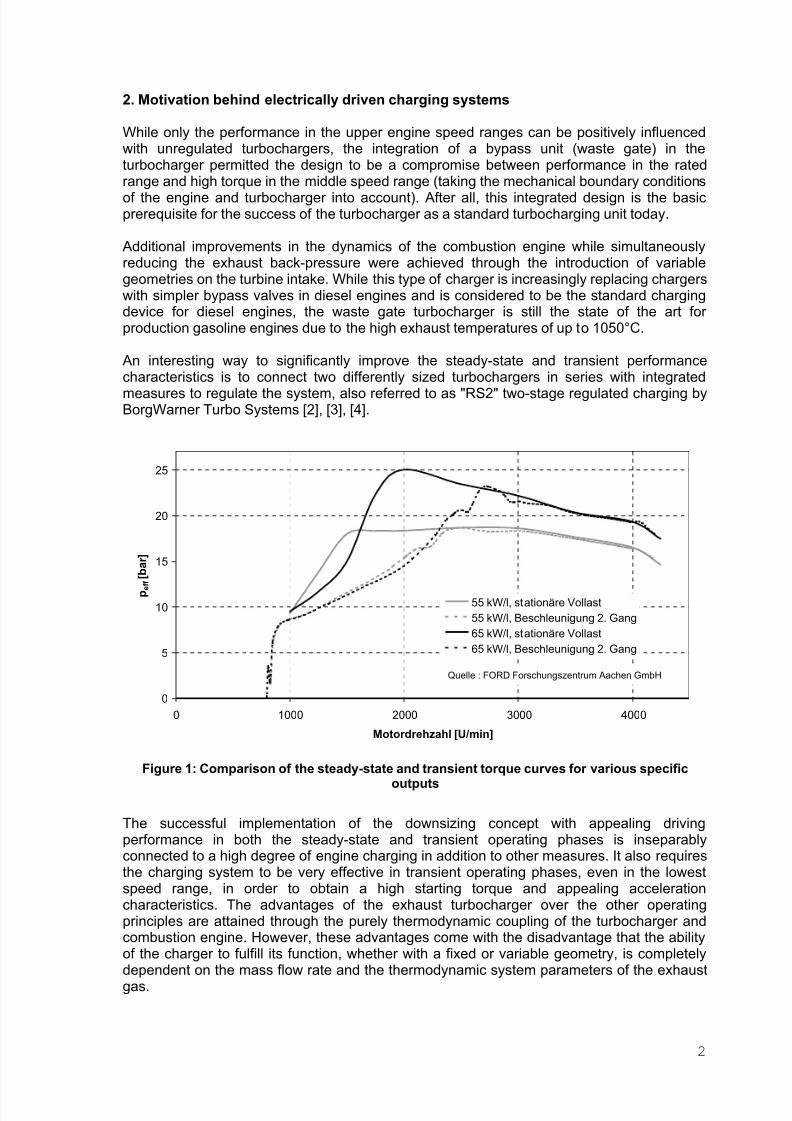
Figure 1: Comparison of the steady-state and transient torque curves for various specificoutputs
The successful implementation of the downsizing concept with appealing drivingperformance in both the steady-state and transient operating phases is inseparablyconnected to a high degree of engine charging in addition to other measures. It also requiresthe charging system to be very effective in transient operating phases, even in the lowestspeed range, in order to obtain a high starting torque and appealing accelerationcharacteristics. The advantages of the exhaust turbocharger over the other operatingprinciples are attained through the purely thermodynamic coupling of the turbocharger andcombustion engine. However, these advantages come with the disadvantage that the ability
of the charger to fulfill its function, whether with a fixed or variable geometry, is completelydependent on the mass flow rate and the thermodynamic system parameters of the exhaustgas.
2
8/3/2019 Designn and Performance of a Innovative Electrically Driven Charging System
http://slidepdf.com/reader/full/designn-and-performance-of-a-innovative-electrically-driven-charging-system 4/20
To more clearly demonstrate this fact, Figure 1 graphs the effective middle pressure of modern diesel engines against the engine speed for various specific outputs, i.e. for anincreasing degree of charging. It becomes clear that the discrepancy between the steady-state and transient response becomes greater with increasing per liter output even withoptimized motor and charger designs, i.e. when the vehicle is accelerated, the steady-statefull-capacity curve is reached at increasingly higher engine speeds as the per liter outputincreases. Currently, this discrepancy can only be overcome using additional charging [5] inwhich the drive energy is independent from the operating state of the combustion engine.
Since mechanically driven auxiliary units need some of the extra energy supplied for their own drive due to their link to the crankshaft, their potential is limited. Hydraulically drivensystems require an accumulator with the corresponding pump. This variant is still problematicin spite of the high power density of the hydromotor in terms of availability (speed andresponse) and the increasing tendency to reduce the size of the oil system. Due to its basicavailability in the vehicle and the known capabilities for producing, storing and routing of electrical energy, the concept of supplying electrical power to the drive of the additional
charging unit is an important implementation concept.It must be remembered that the development of an electrically driven charging system mustmatch the capabilities and remain within the limits of the electrical vehicle electrical system.Since the introduction of a 42 V vehicle electrical system with an increased capacity hasbeen delayed for various reasons and, when introduced in production models, will probablybe seen first in the top class of vehicles, most effort has been concentrated on a modifiedand higher performance 12 V vehicle electrical system. However, this development work isnot only being promoted rapidly for its potential use for electrically driven charging devices,but also for other electricity- consuming devices as well. If you take a look at the capacity of vehicle electrical systems today and reflect on the new capabilities of a 12V-based system,then it becomes clear that electrical power support primarily only comes into question for the
transient operating states of the combustion engine. This is due to the electrical outputrequired for the charging device, the additional output available from the vehicle electricalsystem and the load on the vehicle electrical system.
3. Ways of providing additional electrical power for charging
Various ways of providing the additional electrical power and accomplishing the charginghave been suggested and engineered. These include machines based on the displacementor flow principle, for example, which utilize the impulse of the flowing column of gas.
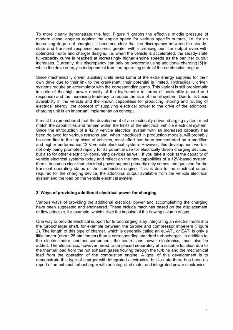
One way to provide electrical support for turbocharging is by integrating an electric motor into
the turbocharger shaft, for example between the turbine and compressor impellers (Figure2). The length of this type of charger, which is generally called an eu-ATL or EAT, is only alittle longer (about 25 mm longer) than a corresponding standard turbocharger. In addition tothe electric motor, another component, the control and power electronics, must also beadded. The electronics, however, need to be placed separately at a suitable location due tothe thermal load from the hot exhaust gases flowing through the turbine and the mechanicalload from the operation of the combustion engine. A goal of this development is todemonstrate this type of charger with integrated electronics, but to date there has been noreport of an exhaust turbocharger with an integrated motor and integrated power electronics.
3
8/3/2019 Designn and Performance of a Innovative Electrically Driven Charging System
http://slidepdf.com/reader/full/designn-and-performance-of-a-innovative-electrically-driven-charging-system 5/20
E l e k t
r o n i k
Ladeluftkühler
Motor
B y p a s s
euATLM
Turbine Verdichter
e-Motor
Figure 2: Diagram of the electrically driven exhaust turbocharger
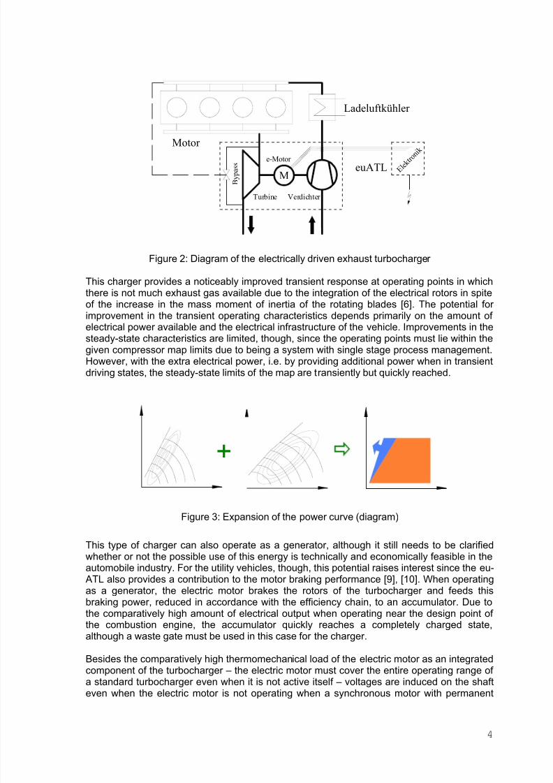
This charger provides a noticeably improved transient response at operating points in whichthere is not much exhaust gas available due to the integration of the electrical rotors in spiteof the increase in the mass moment of inertia of the rotating blades [6]. The potential for improvement in the transient operating characteristics depends primarily on the amount of electrical power available and the electrical infrastructure of the vehicle. Improvements in thesteady-state characteristics are limited, though, since the operating points must lie within thegiven compressor map limits due to being a system with single stage process management.However, with the extra electrical power, i.e. by providing additional power when in transientdriving states, the steady-state limits of the map are transiently but quickly reached.
+
Figure 3: Expansion of the power curve (diagram)
This type of charger can also operate as a generator, although it still needs to be clarifiedwhether or not the possible use of this energy is technically and economically feasible in theautomobile industry. For the utility vehicles, though, this potential raises interest since the eu-ATL also provides a contribution to the motor braking performance [9], [10]. When operatingas a generator, the electric motor brakes the rotors of the turbocharger and feeds thisbraking power, reduced in accordance with the efficiency chain, to an accumulator. Due tothe comparatively high amount of electrical output when operating near the design point of the combustion engine, the accumulator quickly reaches a completely charged state,although a waste gate must be used in this case for the charger.
Besides the comparatively high thermomechanical load of the electric motor as an integrated
component of the turbocharger – the electric motor must cover the entire operating range of a standard turbocharger even when it is not active itself – voltages are induced on the shafteven when the electric motor is not operating when a synchronous motor with permanent
4

8/3/2019 Designn and Performance of a Innovative Electrically Driven Charging System
http://slidepdf.com/reader/full/designn-and-performance-of-a-innovative-electrically-driven-charging-system 6/20
magnets is used. This has a negative effect on the operation of the turbocharger. Based onthe results of a comparative system study, emphasis is being placed on pursuing another electrically driven charging system at BorgWarner Turbo Systems due to its advantages [2],[8] :
This system is based on the use of a flow compressor driven by an electric motor and iscalled the "eBooster" by BorgWarner Turbo Systems. The component is designed to beplaced before or after a standard turbocharger (Figure 4, Figure 5). In contrast to electricallydriven turbochargers, it operates as a two-stage system of two turbomachines connected inseries, i.e. the pressure ratios of the two charging units are multiplied. Through the use of two flow compressors it is possible to match the two units and/or to optimize them for theparticular application and expand the power curve of the charging system (Figure 3), whichalso is of particular interest for providing extra steady-state electrical power. The eBooster and exhaust turbocharger represent separate units connected by hoses. This results inadditional advantages since the electrical and electronic components are smaller than for theelectrically driven charger when the thermomechanical load is positioned similarly. It ispossible without too much effort to integrate the power and control, which would yield
advantages in terms of the electromagnetic compatibility. If the cooling system cannot beused or there is not enough space, this challenge could still be solved using alternativeschemes.
M
Ladeluftkühler
V e n t i l
Motor
B y p a s s
Turbine
Verdichter
e-Motor
E l e k t
r o n i k
Verdichter
Figure 4: eBooster charging system, eBooster before the turbocharger
5
8/3/2019 Designn and Performance of a Innovative Electrically Driven Charging System
http://slidepdf.com/reader/full/designn-and-performance-of-a-innovative-electrically-driven-charging-system 7/20
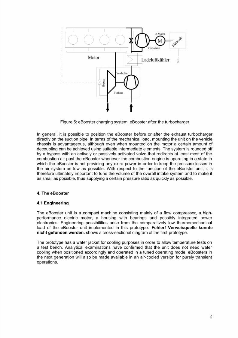
Figure 5: eBooster charging system, eBooster after the turbocharger
In general, it is possible to position the eBooster before or after the exhaust turbocharger directly on the suction pipe. In terms of the mechanical load, mounting the unit on the vehiclechassis is advantageous, although even when mounted on the motor a certain amount of decoupling can be achieved using suitable intermediate elements. The system is rounded off by a bypass with an actively or passively activated valve that redirects at least most of thecombustion air past the eBooster whenever the combustion engine is operating in a state inwhich the eBooster is not providing any extra power in order to keep the pressure losses inthe air system as low as possible. With respect to the function of the eBooster unit, it is
therefore ultimately important to tune the volume of the overall intake system and to make itas small as possible, thus supplying a certain pressure ratio as quickly as possible.
4. The eBooster
4.1 Engineering
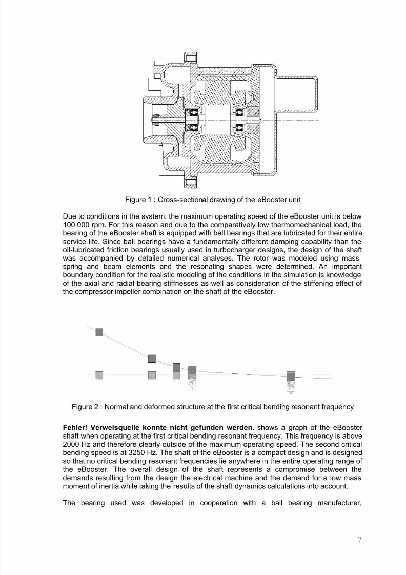
The eBooster unit is a compact machine consisting mainly of a flow compressor, a high-performance electric motor, a housing with bearings and possibly integrated power electronics. Engineering possibilities arise from the comparatively low thermomechanicalload of the eBooster unit implemented in this prototype. Fehler! Verweisquelle konnte
nicht gefunden werden. shows a cross-sectional diagram of the first prototype.
The prototype has a water jacket for cooling purposes in order to allow temperature tests ona test bench. Analytical examinations have confirmed that the unit does not need water cooling when positioned accordingly and operated in a tuned operating mode. eBoosters inthe next generation will also be made available in an air-cooled version for purely transientoperations.
6
8/3/2019 Designn and Performance of a Innovative Electrically Driven Charging System
http://slidepdf.com/reader/full/designn-and-performance-of-a-innovative-electrically-driven-charging-system 8/20
Figure 1 : Cross-sectional drawing of the eBooster unit
Due to conditions in the system, the maximum operating speed of the eBooster unit is below100,000 rpm. For this reason and due to the comparatively low thermomechanical load, thebearing of the eBooster shaft is equipped with ball bearings that are lubricated for their entireservice life. Since ball bearings have a fundamentally different damping capability than theoil-lubricated friction bearings usually used in turbocharger designs, the design of the shaftwas accompanied by detailed numerical analyses. The rotor was modeled using mass,spring and beam elements and the resonating shapes were determined. An importantboundary condition for the realistic modeling of the conditions in the simulation is knowledgeof the axial and radial bearing stiffnesses as well as consideration of the stiffening effect of
the compressor impeller combination on the shaft of the eBooster.
Figure 2 : Normal and deformed structure at the first critical bending resonant frequency
Fehler! Verweisquelle konnte nicht gefunden werden. shows a graph of the eBooster shaft when operating at the first critical bending resonant frequency. This frequency is above2000 Hz and therefore clearly outside of the maximum operating speed. The second criticalbending speed is at 3250 Hz. The shaft of the eBooster is a compact design and is designedso that no critical bending resonant frequencies lie anywhere in the entire operating range of the eBooster. The overall design of the shaft represents a compromise between thedemands resulting from the design the electrical machine and the demand for a low massmoment of inertia while taking the results of the shaft dynamics calculations into account.
The bearing used was developed in cooperation with a ball bearing manufacturer,
7
8/3/2019 Designn and Performance of a Innovative Electrically Driven Charging System
http://slidepdf.com/reader/full/designn-and-performance-of-a-innovative-electrically-driven-charging-system 9/20
accompanied by numerical calculations. Depending on the mounting position of theeBooster, the bearings are loaded radially by the weight of the shaft and possibly by aresidual imbalance. In contrast to standard turbochargers the thrust generated by theoperation of the compressor is not partially compensated. The load is distributed axially onthe bearing. Due to the operating principle of the eBooster, all forces except for the inherentweight of the shaft appear transiently. The shaft of the eBooster is accelerated in the shortestpossible time from a complete stop or from a base idling speed to its final speed. The ballsand bearing retainer are subject during this time to heavy strain. Classic methods for calculating bearing design durability can only provide partially qualified results for thecumulative load demonstrated in this case during high rpm speeds.
The bearing of the eBooster shaft is produced using hybrid bearings. These bearings arecharacterized by metallic rolling rings and ceramic bearing balls. Hybrid bearings expand thelimits of applicability of metallic ball bearings, especially with respect to speed. Due to thelower density of the ceramic bearing ball material, smaller dynamic forces are applied to theset of bearing balls at the same boundary conditions. The bearings are filled with a suitablegrease that lubricates the bearing for the entire service life of the machine. The functionality
and durability of this grease must be guaranteed for a comparatively wide temperature rangeand is therefore subject at each start-up to a substantial shearing load.
Important for the functionality of the bearing is that the sizes of the bearing seats on thehousing and shaft are matched. The bearings are preloaded axially by a defined load and aretherefore always subject to a minimum load. On the one hand, this guarantees that thermaldifferential expansion can be withstood within certain limits, and on the other hand that thebearings never have any axial play in any operating state, which would in turn result insignificant degradation of the service life.
4.2 Voltage levels
In addition to the examinations related to the technical advantages of the eBooster system inthe vehicle in terms of thermodynamics and combustion, the interaction and the integration of the system in an automobile electrical system must also be examined. If the energyconsumption is relatively low during a boosting phase, that is at only a few kJ, then the short-term energy extraction during kW range consumption periods can be considered a challengefor a modern vehicle electrical system. The load placed on the vehicle electrical systemduring a boost phase is about the same as when starting. Since the vehicle electrical systemof today is designed so that the one-time start-up procedure (especially when performed atlow temperatures and when followed by a short driving period) almost reaches theperformance capability limits of an electrical system battery, then frequent loading of thevehicle electrical system on this order places the usefulness of such a system in question.
A promising idea arising in previous years was the idea of introducing a higher-capacityvehicle electrical system with a higher voltage called the 36V (or, during the rechargingphase, the 42V) vehicle electrical system. During this time it was decided to design theeBoosters of the first and second generation for an operating voltage of 42V. In themeantime, however, automobile manufacturers have shied away from introducing the 42Velectrical system for reasons of component availability, compatibility with the current vehicleelectrical system and the substantial cost as well. Development work is therefore beingconcentrated again on higher-performance 12V electrical systems.
In this case there are several possibilities that are primarily concerned with providing highperformance quickly with the help of additional intermediate electrical storage with higher power densities than commercial lead acid batteries. In such systems the use of theeBooster also makes sense for existing vehicle platforms. Current ideas tend towards the
8
8/3/2019 Designn and Performance of a Innovative Electrically Driven Charging System
http://slidepdf.com/reader/full/designn-and-performance-of-a-innovative-electrically-driven-charging-system 10/20
integration of the system in the existing 12V electrical system without negatively affecting theperformance or, in particular, the stability of the voltage.
4.3 Electric motor
The design and engineering of a suitable drive motor is also based in this application on thedemands resulting from the torque requirement of the compressor impeller as well as on theextremely short startup time, which results in an additional, considerable torque requirementto accelerate the rotating masses. Emphasis is also placed on the demand for a robust aswell as economical design.
An electric motor with mechanical commutation, which is generally used as an economicalalternative in each vehicle for most drive applications, cannot be used in this case due to thehigh speeds and the associated dwindling reliability of the commutator/brush system. For thisreason, only electronically commuted motors can be used, i.e. permanent magnet-excitedsynchronous machines (SYM), reluctance machines (switched reluctance machine, SRM) or
asynchronous machines (ASM) (Figure 6) with the appropriate electronics.The most attractive solution without any doubt initially appears to be the SYM due to its loss-free provision of the excited magnetic field, the high efficiency generally resulting from thisfact and its insensitivity to the design size of the air gap. One problem with this solution,though, is the limited tensile strength of the permanent magnet material, which can only becompensated for through additional design measures such as straps, for example.Furthermore, the constant excitement creates interference, even when there is no load andthe machine is turning and the hysteresis and eddy current losses created in the ironproduce a braking moment of inertia. The SYM requires a rotor position detector.
The SRM is interesting from a manufacturing point of view. Its stator coils are easy to
manufacture and can be pushed through the hole in the stator and stuck on the teeth of thestator. The rotor has an especially low mass moment of inertia due to its characteristic toothcontour. The coil-end face of the rotor is covered so that the rotor itself does not generate toomany losses due to friction with the air. This machine also requires a device to detect theposition of the rotor, and this device must also be able to precisely detect the rotor angle.
The ASM design with the cast aluminum rotor cage is considered to be especially robust, iswell-known in the field of manufacturing technology and can be operated without a specialrotor position detector. It has one disadvantage in that heat that needs to be drawn off isgenerated in the rotor due to the currents in the aluminum cage. In terms of the complexity of the coils, the SYM coils are as complex as a coil for three-phase current with three windings.
The samples of the first and second generation were equipped with an ASM, and the highspeeds were reached using it in the prescribed time without any problem. A simple speedsensor allowed us to check the current speed on the test bench. The machine acceleratesaccording to a predefined speed ramp given by the control electronics software that dependson the compressor impeller used. Regulation of the slip ensures that no undefined statesarise when the load changes. The thermal stresses that arise only permit periodic duty for such a small motor. With additional temperature sensors for monitoring purposes, morerobust operation was made possible on the internal combustion engine test bench as well asin the vehicle.
9

8/3/2019 Designn and Performance of a Innovative Electrically Driven Charging System
http://slidepdf.com/reader/full/designn-and-performance-of-a-innovative-electrically-driven-charging-system 11/20
Figure 6:
Figure 8 : Permanent magnet-excited synchronous machine (SYM), reluctance machine(switched reluctance machine, SRM), asynchronous machine (ASM).
4.4 Power electronics
After basic proof of the functionality was attained with the first eBooster generation,emphasis was placed in the second generation on a robust electronic control systemdesigned to be as flexible as possible. With this control system it was possible on the internalcombustion engine test bench as well as in the vehicle to determine the requirements profilenecessary to create detailed technical specifications.
The electronic components are subject to high loads when used in internal combustionengine applications. This applies to the temperature range as well as to the high currents andthe electromagnetic compatibility to be attained. In addition, there are the strains resultingfrom the frequent mounting and removal of the unit in the course of the test phases. While itshould be considered a goal to integrate the power electronics in the eBooster housing, it ismostly an advantage when the electronics are protected from accidental, improper operationor incorrect connections during the first system tests on the test bench. For this reason thesamples were equipped with a polarity reversal protection device in spite of the high currentlevels. In this case there is potential for improvement with respect to the achievableefficiency. The temperature of the power electronics is monitored separately from thetemperature of the engine and is installed in a housing available as a mass-producedcomponent. "Robust" operation is therefore possible.
There are three main control signals used to control the eBooster. Two of them control thestartup and final speed, respectively, and the third controls the acceleration time. Theelectronics output a speed signal for control purposes, but also to permit pressure control,and have a second operating mode that permits continuous adjustment of the compressor impeller speed.
The circuits of the power transistors allow a regulated current to be applied to the coils of thethree-phase electric machine in both directions. There is also an operating mode that permitspulse width modulated power curves for the continuous adjustment of the speed and asquare-shaped curve for fast control and low losses in the electronics. Since the size of theelectric machine is about the same as that of a 30 W machine operating in the system atroom temperature, continuous operation at higher performance levels is impossible due to
the thermal load. That is why there is no power feedback, especially considering the fact thatintervention in the energy balance has not been sufficiently examined in terms of thethermodynamics or the electric system.
10

8/3/2019 Designn and Performance of a Innovative Electrically Driven Charging System
http://slidepdf.com/reader/full/designn-and-performance-of-a-innovative-electrically-driven-charging-system 12/20
5. Results
While emphasis was placed during the first development phase on the basic functionality of the eBooster unit [8], emphasis was placed during the second phase on demonstratingreliable prototypes to prove the effectiveness of the eBooster charging system on thecombustion engine in test bench operations as well as in vehicle tests. The developmentstatus will be discussed in the following based on experimental and numerical results.
5.1 Numerical results
After the first numerical tests using suitable procedures were performed externally on theeBooster in close cooperation with a technology institute [13, 14], BorgWarner TurboSystems used the interim period to garner expertise in numerical simulation relating toturbocharger design and provision of direct support to the development work [12]. The GTPower computer program, often used by customers due to its high performance and synergyeffects with development departments, was used. The program can model transient
processes in addition to the steady-state response, which is especially important for theeBooster charging system.
One requirement for the realistic modeling of the transient processes is the calibration of thecalculated model based on the data obtained from the steady-state experiments conductedon the corresponding combustion engine and the input of additional parameters thatdetermine the transient response (for example, the mass moment of inertia of the rotatingblades).
Due to the increase in charging pressure achievable even at low engine speeds, it is possibleto improve the dynamic driving response. The driving response improves noticeably due tothe fact that the charging pressure is built up quickly and the resulting torque is higher. In the
simulation the influence of other compressors on the start-up response of the eBooster andits effect on the combustion engine can be estimated quickly and easily. The mass momentof inertia of the rotor increases unproportionally as the rotor diameter increases. The designof the eBooster compressor impeller represents a compromise between a high pressure ratioat the lowest possible speed (which means a large diameter wheel) and the lowest possiblemass moment of inertia (which demands a small diameter wheel) in order to reach this speedin the shortest time possible.
Figure 7 shows the build-up of the charging pressure with and without the eBooster for a loadchange at 2000 rpm. The torque of the engine increases according to the charging pressure.The transient calculation with the integrated version of the eBooster shows a dramaticallyimproved dynamic response. The results of the simulation closely mirror the measurements
taken on the motor test bench. In terms of the location of the charging system, considerableadvantages were detected in the case examined in the simulation when the eBooster wasplaced after the turbocharger compressor.
0,00
0,50
1,00
1,50
2,00
2,50
L
a d e d r u c k [ m b a r ]
mit eBooster
ohne eBooster
11
8/3/2019 Designn and Performance of a Innovative Electrically Driven Charging System
http://slidepdf.com/reader/full/designn-and-performance-of-a-innovative-electrically-driven-charging-system 13/20
0
50
100
150
200
250
300
350
1 2 3 4 5 6 7
Zeit [s]
D r e h
m o m e n t [ N m ]
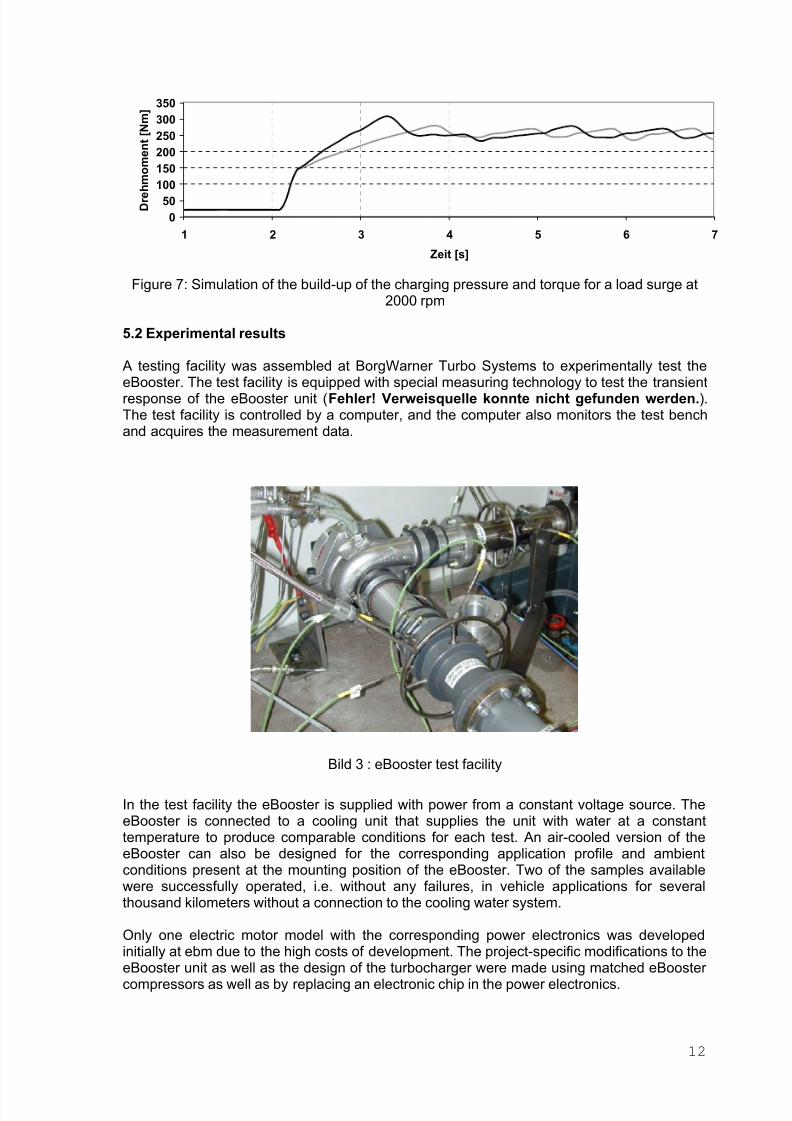
Figure 7: Simulation of the build-up of the charging pressure and torque for a load surge at
2000 rpm
5.2 Experimental results
A testing facility was assembled at BorgWarner Turbo Systems to experimentally test the
eBooster. The test facility is equipped with special measuring technology to test the transientresponse of the eBooster unit (Fehler! Verweisquelle konnte nicht gefunden werden.).The test facility is controlled by a computer, and the computer also monitors the test benchand acquires the measurement data.
Bild 3 : eBooster test facility
In the test facility the eBooster is supplied with power from a constant voltage source. TheeBooster is connected to a cooling unit that supplies the unit with water at a constanttemperature to produce comparable conditions for each test. An air-cooled version of theeBooster can also be designed for the corresponding application profile and ambientconditions present at the mounting position of the eBooster. Two of the samples availablewere successfully operated, i.e. without any failures, in vehicle applications for severalthousand kilometers without a connection to the cooling water system.
Only one electric motor model with the corresponding power electronics was developed
initially at ebm due to the high costs of development. The project-specific modifications to theeBooster unit as well as the design of the turbocharger were made using matched eBooster compressors as well as by replacing an electronic chip in the power electronics.
12
8/3/2019 Designn and Performance of a Innovative Electrically Driven Charging System
http://slidepdf.com/reader/full/designn-and-performance-of-a-innovative-electrically-driven-charging-system 14/20
In addition to several eBooster-specific compressors, models 1870 EAA and 2075 ECD havebeen used to date. Due to the low mass moment of inertia, acceleration times are about 0.2 sfaster and higher speeds are reached with the 1870 EAA compressor for a lower power requirement. The pressure and mass flow remain below those of the 2075 ECD inaccordance with the compressor maps.
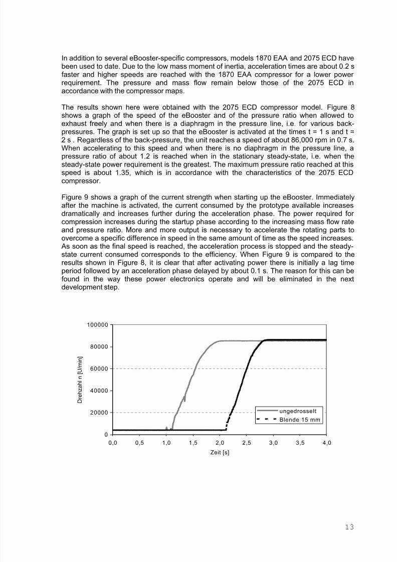
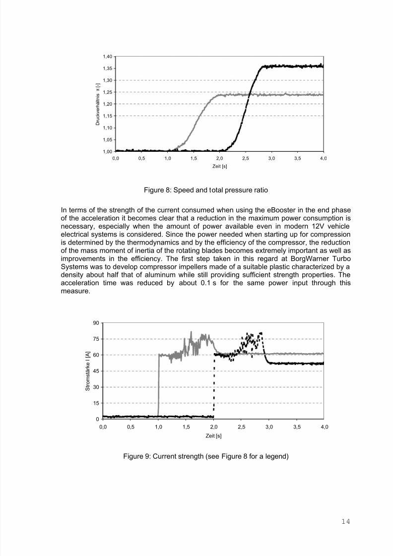
The results shown here were obtained with the 2075 ECD compressor model. Figure 8shows a graph of the speed of the eBooster and of the pressure ratio when allowed toexhaust freely and when there is a diaphragm in the pressure line, i.e. for various back-pressures. The graph is set up so that the eBooster is activated at the times t = 1 s and t =2 s . Regardless of the back-pressure, the unit reaches a speed of about 86,000 rpm in 0.7 s.When accelerating to this speed and when there is no diaphragm in the pressure line, apressure ratio of about 1.2 is reached when in the stationary steady-state, i.e. when thesteady-state power requirement is the greatest. The maximum pressure ratio reached at thisspeed is about 1.35, which is in accordance with the characteristics of the 2075 ECDcompressor.
Figure 9 shows a graph of the current strength when starting up the eBooster. Immediatelyafter the machine is activated, the current consumed by the prototype available increasesdramatically and increases further during the acceleration phase. The power required for compression increases during the startup phase according to the increasing mass flow rateand pressure ratio. More and more output is necessary to accelerate the rotating parts toovercome a specific difference in speed in the same amount of time as the speed increases.As soon as the final speed is reached, the acceleration process is stopped and the steady-state current consumed corresponds to the efficiency. When Figure 9 is compared to theresults shown in Figure 8, it is clear that after activating power there is initially a lag timeperiod followed by an acceleration phase delayed by about 0.1 s. The reason for this can befound in the way these power electronics operate and will be eliminated in the next
development step.
0
20000
40000
60000
80000
100000
0,0 0,5 1,0 1,5 2,0 2,5 3,0 3,5 4,0
Zeit [s]
D r e h z a h
l n [ U / m i n ]
ungedrosselt
Blende 15 mm
13
8/3/2019 Designn and Performance of a Innovative Electrically Driven Charging System
http://slidepdf.com/reader/full/designn-and-performance-of-a-innovative-electrically-driven-charging-system 15/20
1,00
1,05
1,10
1,15
1,20
1,25
1,30
1,35
1,40
0,0 0,5 1,0 1,5 2,0 2,5 3,0 3,5 4,0
Zeit [s]
D r u c k v e r h ä l t n i s
π
[ - ]
Figure 8: Speed and total pressure ratio
In terms of the strength of the current consumed when using the eBooster in the end phaseof the acceleration it becomes clear that a reduction in the maximum power consumption isnecessary, especially when the amount of power available even in modern 12V vehicleelectrical systems is considered. Since the power needed when starting up for compressionis determined by the thermodynamics and by the efficiency of the compressor, the reductionof the mass moment of inertia of the rotating blades becomes extremely important as well asimprovements in the efficiency. The first step taken in this regard at BorgWarner TurboSystems was to develop compressor impellers made of a suitable plastic characterized by adensity about half that of aluminum while still providing sufficient strength properties. The
acceleration time was reduced by about 0.1 s for the same power input through thismeasure.
0
15
30
45
60
75
90
0,0 0,5 1,0 1,5 2,0 2,5 3,0 3,5 4,0
Zeit [s]
S t r o m
s t ä r k e I [ A ]
Figure 9: Current strength (see Figure 8 for a legend)
14
8/3/2019 Designn and Performance of a Innovative Electrically Driven Charging System
http://slidepdf.com/reader/full/designn-and-performance-of-a-innovative-electrically-driven-charging-system 16/20
6. Outlook and additional procedures
The goal of this prototype was to prove the effectiveness of the eBooster in conjunction withthe turbocharger on the combustion engine in test bench operations and vehicle tests as wellas to prove its reliability and robustness. This effectiveness was demonstrated in severalprojects conducted in close cooperation with the customer for gasoline engines and dieselengines.
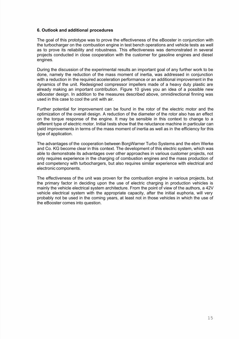
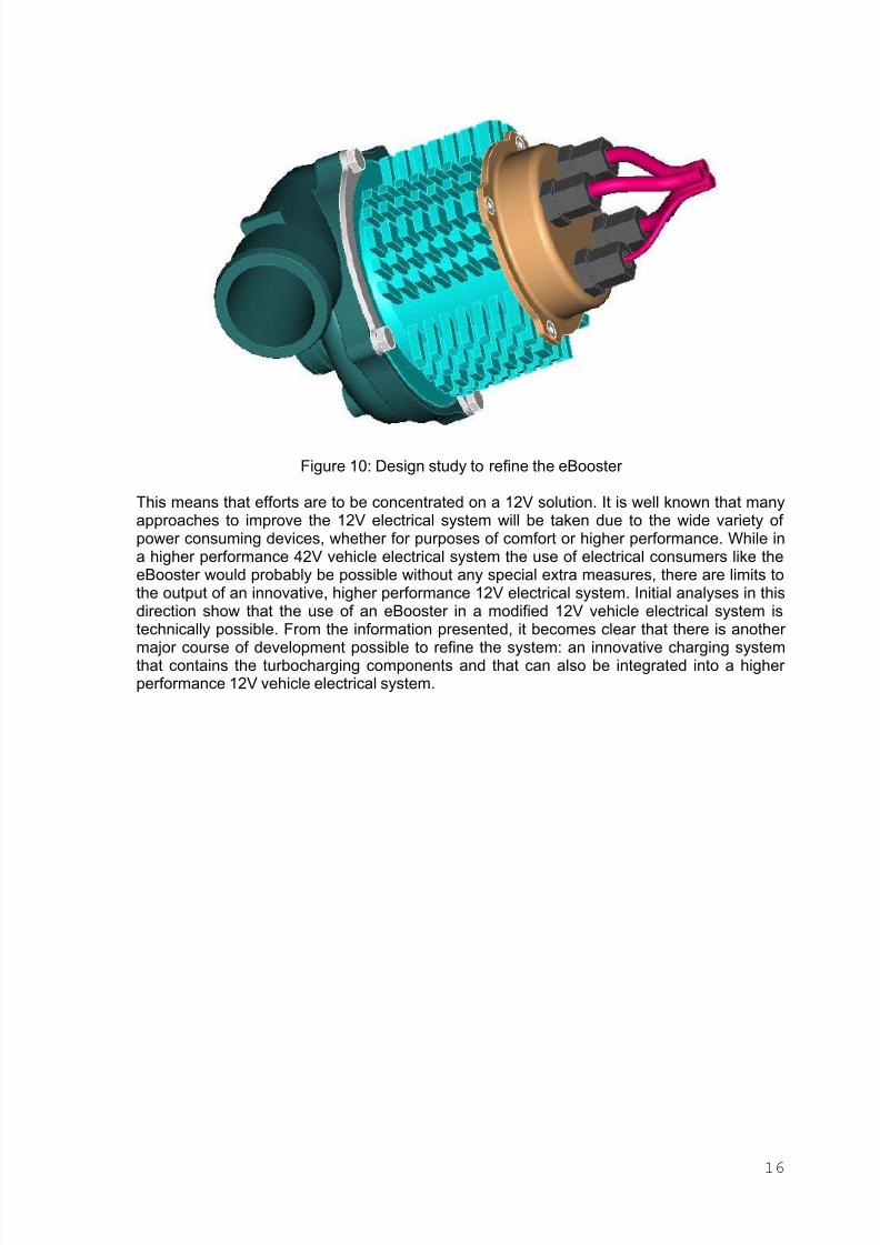
During the discussion of the experimental results an important goal of any further work to bedone, namely the reduction of the mass moment of inertia, was addressed in conjunctionwith a reduction in the required acceleration performance or an additional improvement in thedynamics of the unit. Redesigned compressor impellers made of a heavy duty plastic arealready making an important contribution. Figure 10 gives you an idea of a possible neweBooster design. In addition to the measures described above, omnidirectional finning wasused in this case to cool the unit with air.
Further potential for improvement can be found in the rotor of the electric motor and the
optimization of the overall design. A reduction of the diameter of the rotor also has an effecton the torque response of the engine. It may be sensible in this context to change to adifferent type of electric motor. Initial tests show that the reluctance machine in particular canyield improvements in terms of the mass moment of inertia as well as in the efficiency for thistype of application.
The advantages of the cooperation between BorgWarner Turbo Systems and the ebm Werkeand Co. KG become clear in this context. The development of this electric system, which wasable to demonstrate its advantages over other approaches in various customer projects, notonly requires experience in the charging of combustion engines and the mass production of and competency with turbochargers, but also requires similar experience with electrical andelectronic components.
The effectiveness of the unit was proven for the combustion engine in various projects, butthe primary factor in deciding upon the use of electric charging in production vehicles ismainly the vehicle electrical system architecture. From the point of view of the authors, a 42Vvehicle electrical system with the appropriate capacity, after the initial euphoria, will veryprobably not be used in the coming years, at least not in those vehicles in which the use of the eBooster comes into question.
15
8/3/2019 Designn and Performance of a Innovative Electrically Driven Charging System
http://slidepdf.com/reader/full/designn-and-performance-of-a-innovative-electrically-driven-charging-system 17/20
Figure 10: Design study to refine the eBooster
This means that efforts are to be concentrated on a 12V solution. It is well known that manyapproaches to improve the 12V electrical system will be taken due to the wide variety of power consuming devices, whether for purposes of comfort or higher performance. While ina higher performance 42V vehicle electrical system the use of electrical consumers like theeBooster would probably be possible without any special extra measures, there are limits tothe output of an innovative, higher performance 12V electrical system. Initial analyses in thisdirection show that the use of an eBooster in a modified 12V vehicle electrical system istechnically possible. From the information presented, it becomes clear that there is another major course of development possible to refine the system: an innovative charging systemthat contains the turbocharging components and that can also be integrated into a higher performance 12V vehicle electrical system.
16

8/3/2019 Designn and Performance of a Innovative Electrically Driven Charging System
http://slidepdf.com/reader/full/designn-and-performance-of-a-innovative-electrically-driven-charging-system 18/20
Bibliography
[1] Schult-Bornemann, K.-H.Mineralölwirtschaft-Der internationale RohölmarktBWK-Das Energie-Fachmagazin, Springer VDI Verlag, Ausgabe 4 / 2001
[2] Hoecker, P.; Pflüger, F.; Jaisle, J. W.; Münz, S.Moderne Aufladekonzepte für PKW Dieselmotoren7. Aufladetechnische Konferenz, Dresden, 28. – 29. September 2000
[3] Oberholz, G.; Pflüger, F.Downsizing- Aufladekonzepte für OttomotorenKonferenz „Downsizingkonzepte für Otto- und Dieselfahrzeugmotoren“, München26.- 27. Juni. 2000
[4] Pflüger, F.Regulated two-stage tur bocharging - KKK’s new charging system for commercial
diesel engines6th International Conference on Turbocharging and Air Management Systems,LondonImechE Conference Transactions, 1998
[5] Krieger K.„Es ist viel besser, Emissionen zu vermeiden, als sie mit Abgasnachbehandlung zusenken“Interview mit K. Krieger, MTZ 4 / 2002, 63. Jahrgang
[6] Shahed, S.M.; Allen, W. ; Lin, E.; Barrios, K.; Birch, K.Elektrisch unterstützte Turboladersysteme für konventionelle, Hybrid- und
BrennstoffzellenantriebeWiener Motorensymposium, Wien, 2000
[7] Kreuter, P.; Bey, R.; Wensing, M.Impulslader für Otto- und DieselmotorenFortschritt-Berichte VDI, Reihe 12, Nr. 455
[8] Hoecker, P.; Jaisle, J.W.; Münz, S.Der eBooster – Schlüsselkomponente eines neuen Aufladesystems von BorgWarner Turbo Systems für PersonenkraftwagenFortschritt-Berichte VDI, Reihe 12, Nr. 455
[9] Zellbeck, H.; Friedrich, J.; Berger, C.Die elektrisch unterstützte Abgasturboaufladung als neues AufladekonzeptMTZ Motortechnische Zeitschrift 60 (1999)
[10] Huber, G.Elektrisch unterstützte ATL-Aufladung (euATL), Schaffung eines neuenFreiheitsgrades bei der motorischen Verbrennung6. Aufladetechnische Konferenz, Dresden, 1. – 2. Oktober 1997
[11] Warnecke, W.„In der Übergangszeit auf fossile Brennstoffe konzentrieren“Interview mit W. Warnecke, MTZ 6 / 2002, 63. Jahrgang
17

8/3/2019 Designn and Performance of a Innovative Electrically Driven Charging System
http://slidepdf.com/reader/full/designn-and-performance-of-a-innovative-electrically-driven-charging-system 19/20
18
[12] Gabriel, H.; Schmitt, F.; Weber, M.; Lingenauber, R.; Schmalzl, H.P.Neue Erkenntnisse bei der variablen Turbinen- und Verdichtergeometrie für dieAnwendung in Turboladern für Pkw-MotorenFortschritt-Berichte VDI, Reihe 12, Nr. 490
[13] Zellbeck, H.; Friedrich, J.Simulation des Beschleunigungsverhaltens von PKW-Ottomotoren mit neuenAufladeverfahrenWiener Motorensymposium, Wien , 1999
[14] Zellbeck, H.; Friedrich, J.Optimierung des dynamischen Verhaltens aufgeladener Verbrennungsmotoren7. Aufladetechnische Konferenz, Dresden, 28. – 29. September 2000

8/3/2019 Designn and Performance of a Innovative Electrically Driven Charging System
http://slidepdf.com/reader/full/designn-and-performance-of-a-innovative-electrically-driven-charging-system 20/20
BorgWarner Turbo SystemsWorlwide Headquarters GmbHMarnheimer Strasse 8867292 Kirchheimbolanden / GermanyPhone: ++49 (0)6352 75 33 0Fax: ++49 (0)6352 75 33 99
BorgWarner Turbo Systems GmbHMarnheimer Strasse 85/8767292 Kirchheimbolanden / GermanyPhone: ++49 (0)6352 403 0Fax: ++49 (0)6352 403 1866
BorgWarner Ltd.
Euroway Industrial EstateBradford BD4 6SEWest Yorkshire / UKPhone: ++44 1274 684 915Fax: ++44 1274 689 671
BorgWarner Turbo SystemsPO Box 15075Asheville, NC 28813/USAPhone: 001 828 684 4000Fax: 001 828 684 4114
BorgWarner Brasil Ltda.Estrada da Rhodia Km 15P.O. Box 654013084-970 Campinas-SP / BrasilPhone: ++55 19 3787 5700Fax: ++55 19 3787 5701
Hitachi Warner Turbo Systems Ltd.3085-5 Higashi Ishikawa Saikouchi, Hitachinaka-shi
Ibaraki-ken312-0052, JapanPhone: +81 (0) 29-276-9388Fax: +81 (0) 29-276-9397
www.turbos.bwauto.com