
Rapid Prototyping of Electrically Small Spherical Wire...
5
General rights Copyright and moral rights for the publications made accessible in the public portal are retained by the authors and/or other copyright owners and it is a condition of accessing publications that users recognise and abide by the legal requirements associated with these rights. • Users may download and print one copy of any publication from the public portal for the purpose of private study or research. • You may not further distribute the material or use it for any profit-making activity or commercial gain • You may freely distribute the URL identifying the publication in the public portal If you believe that this document breaches copyright please contact us providing details, and we will remove access to the work immediately and investigate your claim. Downloaded from orbit.dtu.dk on: Apr 22, 2018 Rapid Prototyping of Electrically Small Spherical Wire Antennas Kim, Oleksiy S. Published in: I E E E Transactions on Antennas and Propagation Link to article, DOI: 10.1109/TAP.2014.2317489 Publication date: 2014 Document Version Early version, also known as pre-print Link back to DTU Orbit Citation (APA): Kim, O. S. (2014). Rapid Prototyping of Electrically Small Spherical Wire Antennas. I E E E Transactions on Antennas and Propagation, 62(7), 3839-3842. DOI: 10.1109/TAP.2014.2317489
Transcript of Rapid Prototyping of Electrically Small Spherical Wire...
General rights Copyright and moral rights for the publications made accessible in the public portal are retained by the authors and/or other copyright owners and it is a condition of accessing publications that users recognise and abide by the legal requirements associated with these rights.
• Users may download and print one copy of any publication from the public portal for the purpose of private study or research. • You may not further distribute the material or use it for any profit-making activity or commercial gain • You may freely distribute the URL identifying the publication in the public portal
If you believe that this document breaches copyright please contact us providing details, and we will remove access to the work immediately and investigate your claim.
Downloaded from orbit.dtu.dk on: Apr 22, 2018
Rapid Prototyping of Electrically Small Spherical Wire Antennas
Kim, Oleksiy S.
Published in:I E E E Transactions on Antennas and Propagation
Link to article, DOI:10.1109/TAP.2014.2317489
Publication date:2014
Document VersionEarly version, also known as pre-print
Link back to DTU Orbit
Citation (APA):Kim, O. S. (2014). Rapid Prototyping of Electrically Small Spherical Wire Antennas. I E E E Transactions onAntennas and Propagation, 62(7), 3839-3842. DOI: 10.1109/TAP.2014.2317489
1
Rapid prototyping of electrically small spherical
wire antennas
Oleksiy S. Kim
Abstract—It is shown how modern rapid prototyping tech-nologies can be applied for quick and inexpensive, but stillaccurate, fabrication of electrically small wire antennas. A wellknown folded spherical helix antenna and a novel sphericalzigzag antenna have been fabricated and tested, exhibiting theimpedance and radiation characteristics in close agreement withthose predicted numerically.
Index Terms—electrically small antennas, spherical antennas,rapid prototyping, 3D printing, selective laser sintering, nanocrys-taline copper
I. INTRODUCTION
A spherical antenna is one of the fundamental concepts in
the theory of electrically small antennas. The concept was
introduced by Chu in [1], where he considered an imaginary
sphere of radius a with no fields inside (except those needed
to make an antenna self-resonant). By evaluating the stored
energy external to the sphere, he derived a lower bound on the
radiation quality factor Q, which is expressed as [2]
QChu =1
(ka)3+
1
(ka)(1)
where k is the free space propagation constant.
Subsequently, lower bounds for Q were derived for vanish-
ingly small spherical antennas with magnetodielectric cores [3],
for arbitrary size spherical antennas with air core [4], for
arbitrary size spherical magnetic dipole antennas with solid
magnetodielectric cores [5], as well as it was shown that the
Chu lower bound could be approached by both electric and
magnetic dipole spherical antennas of arbitrary size using metal
cores coated with a highly permeable magnetic material [6],
[7]. The latter two combined in a dual-mode configuration form
an antenna that is self-resonant with the Q approximately half
of the Chu lower bound [8].
Numerous practical configurations of spherical antennas
have been proposed and tested against the bounds, e.g. [9]–[11].
Most of these antennas were of wire type, and it was natural
to try to fabricate them using conductig wires. This required
substantial skills in handwork, while satisfactory results were
not guaranteed. Moreover, the repetability was very poor.
More controllable methods include printing on planar [10]
and curved [12], [13] substrates, direct transfer patterning [14],
and even injection of liquid metal alloy into an inflatable
substrate [15]. All these techniques rely on sophisticated tech-
nology and equipment, which is not readily available; and
they require some kind of dielectric substrate, which always
increases the Q [16].
On the other hand, the recent decade’s explosive growth of
rapid prototyping (RP) techniques has made them available to
O. S. Kim is with the Department of Electrical Engineering, Section forElectromagnetics, Technical University of Denmark, Kgs. Lyngby, Denmarke-mail: [email protected] received December xx, 2013; revised February xx, 2014.
an ordinary consumer. These are stereolithography (SLA), se-
lective laser sintering (SLS), three-dimensional printing (3DP),
fused deposition modeling (FDM) just to mention a few [17].
Nowadays, RP technology is not limited to prototype building;
it is also widely used for fabrication of final products and its
parts.
In this paper, it is shown how a rapid prototyping technique
can be applied for fabrication of electrically small spherical
wire antennas. The approach is exemplified by a well-known
folded spherical helix antenna and a novel spherical zigzag
antenna; both are of the electric dipole type. Printed in dielec-
tric, the antennas are subsequently coated with a conductive
layer. A good conductivity of the latter is crititcal for achieving
a high radiation efficiency of electrically small antennas, as
discussed in Section II. The measured impedance and radiation
characteristics of the fabricated antennas are presented in
Section III. Concluding remarks are given in Section IV.
II. ANTENNAS TO PRINT
Among a variety of configurations, two spherical wire anten-
nas have been selected for testing the RP technology. A folded
spherical helix antenna was selected as the most well-known
spherical wire antenna, which is often used as a reference for
new antenna designs as well as a test object for new fabrication
techniques. The second antenna was a spherical zigzag antenna,
a modification of a spherical meander antenna first presented
in [18]. The design needed experimental validation and the RP
testing offered such an opportunity.
1) Folded Spherical Helix Antenna: consists of a number of
identical wire helices wound on a spherical surface of radius
r0 [9]. One of the helices is attached, through a metal ground
plane, to the inner conductor of a coaxial feeding cable. The
resonance frequency is adjusted by the number of turns in the
helices, whereas the input resistance at the resonance takes
discrete values with changing the number of helices. The radius
of the antenna was selected to be r0 = 25 mm with the radius
of the wires w = 0.64 mm. A configuration of four helices
with 0.95 turns in each exhibits 50 ohms input impedance at
the resonance frequency of 750 MHz. The resulting electrical
size of the antenna is ka = k(r0 + w) = 0.4.
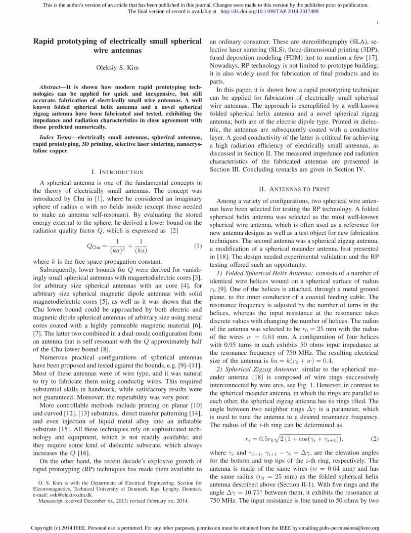
2) Spherical Zigzag Antenna: similar to the spherical me-
ander antenna [18] is composed of wire rings successively
interconnected by wire arcs, see Fig. 1. However, in contrast to
the spherical meander antenna, in which the rings are parallel to
each other, the spherical zigzag antenna has its rings tilted. The
angle between two neighbor rings ∆γ is a parameter, which
is used to tune the antenna to a desired resonance frequency.
The radius of the i-th ring can be determined as
ri = 0.5r0√
2 (1 + cos(γi + γi+1)), (2)
where γi and γi+1, γi+1 − γi = ∆γ, are the elevation angles
for the bottom and top tips of the i-th ring, respectively. The
antenna is made of the same wires (w = 0.64 mm) and has
the same radius (r0 = 25 mm) as the folded spherical helix
antenna described above (Section II-1). With five rings and the
angle ∆γ = 10.75◦ between them, it exhibits the resonance at
750 MHz. The input resistance is fine tuned to 50 ohms by two
This is the author's version of an article that has been published in this journal. Changes were made to this version by the publisher prior to publication.The final version of record is available at http://dx.doi.org/10.1109/TAP.2014.2317489
Copyright (c) 2014 IEEE. Personal use is permitted. For any other purposes, permission must be obtained from the IEEE by emailing [email protected].
2
r0
coaxial feed
(a)
γiγi+1
∆γ
r0
coaxial feed
(b)
Fig. 1. Cross sections of spherical meander antenna (a) and spherical zigzagantenna (b), both fed by a coaxial cable through a ground plane. A 3D viewof each antenna is shown in the respective inset.
shorting pins placed symmetrically opposite to the excitation
pin, in a way described in [18].
Tilting of the rings affects negligibly the far-field radiation;
the radiation pattern of the spherical meander and zigzag anten-
nas is that of an electrically small electric dipole (or monopole,
in a ground plane is utilized) with the cross-polarization
(according to Ludwig’s second definition [19]) generated by
the TE11 spherical mode excited by the antennas. The cross-
polarization is zero in the XZ-plane (Fig. 2b), because this
is a symmetry plane for the antenna geometry. This property
distinguishes the spherical meander and zigzag antennas from
the folded spherical helix antenna, whose cross-polarization is
omnidirectional (Fig. 2a).
Tilted rings give the zigzag antenna a clear advantage over
its meander counterpart in terms of the radiation efficiency,
when the conductivity of the wires, the antennas are made of, is
finite. This is illustrated in Fig. 3, where the radiation efficiency
computed with CST is plotted for the spherical meander and
zigzag antennas, as well as for the folded spherical helix an-
tenna, versus the conductivity of the wires. As the conductivity
decreases, the radiation efficiency drops for all antennas, but
at different rates. The degradation is slowest for the folded
spherical helix antenna, while the fastest deterioration of the
efficiency occurs for the spherical zigzag antenna. Nevertheless,
for good conductivity, the spherical zigzag antenna outperforms
not only the spherical meander antenna, but also the folded
spherical helix antenna, when the conductivity approaches the
value for copper. The reason is that electric currents on all parts
of the zigzag antenna — including the tilted rings — contribute
to the far-field radiation, whereas in the meander antenna, the
far-field is due to the vertical segments, while the parallel rings
contribute mainly to the reactive near-field, leading to increased
losses.
(a)
(b)
Fig. 2. Cross-polarization radiation pattern of the folded spherical helixantenna (a), and the spherical meander and zigzag antennas (b).
70
75
80
85
90
95
100
105
106
107
108
Rad
iati
on e
ffic
iency
, %
Conductivity, S/m
folded spherical helix
spherical meander antenna
spherical zigzag antenna
Fig. 3. Computed radiation efficiency versus the conductivity of the wires.The conductivity for copper (5.96 · 10
7 S/m) is marked by a vertical dottedline.
This result, besides confirming a high sensitivity of elec-
trically small antennas to conductive losses, shows that in
different ranges of the attained conductivity, different antennas
This is the author's version of an article that has been published in this journal. Changes were made to this version by the publisher prior to publication.The final version of record is available at http://dx.doi.org/10.1109/TAP.2014.2317489
Copyright (c) 2014 IEEE. Personal use is permitted. For any other purposes, permission must be obtained from the IEEE by emailing [email protected].
3
perform better than others. When moderate to good conduc-
tivity (better than 3 · 106 S/m) is expected to be achieved in
fabrication, the folded spherical helix antenna and the spherical
zigzag antenna are the antennas of choice.
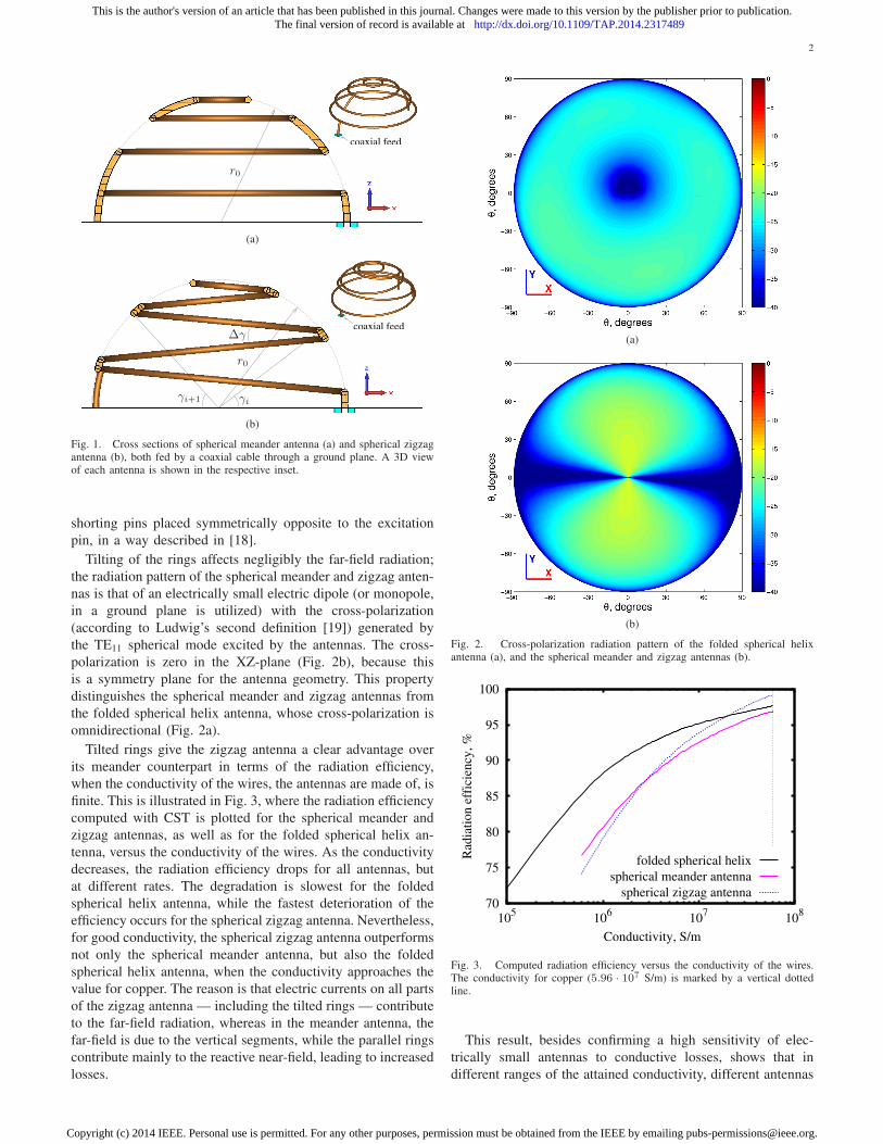
III. FABRICATION AND MEASUREMENTS
A solid CAD model for each of the antennas to be printed
using SLS technique consisted of the corresponding wire
structure and a solid cylindrical pedestal with a hole for an
SMA connector. To counteract gravity induced deformations
experienced during the first attempt of fabricating the folded
spherical helix antenna with an RP technology [20], the wire
structure was reinforced with thin supporting arcs.
Printed in dielectric, the antenna prototypes required conduc-
tive coating. In [20], it was done with copper paint; however,
the results were not satisfactory, as measurements showed
radiation efficiency of only 80%. Therefore, an alternative
conductive coating technique was utilized — coating with poly-
crystalline copper. By this technique, conductivities comparable
to bulk copper of the corresponding thickness can be achieved
on a dielectric surface, or on a part of it, as the coating
can be deposited selectively. Such conductivity is about two
orders of magnitude better than that of the copper paint used
in [20]. The process is relatively cheap and has been already
commercialized. The entire structure including the pedestal,
but excluding the supporting arcs, was coated in both antenna
prototypes. The central pin of an SMA connector was attached
to the wire structure with a conductive glue. Finally, the printed
and coated structures were embedded in a circular aluminum
ground plane of 770 mm in diameter. The resulting prototypes
of the folded spherical helix and spherical zigzag antennas are
shown in Fig. 4.
Input impedance measurements showed that both antennas
were well matched in vicinity of the expected resonance
frequency of 750 MHz (Fig. 5). The radiation efficiency at
the resonance, measured by the Wheeler cap method, is 94%
and 90% for the folded spherical helix antenna and spherical
zigzag antenna, respectively1. Although the obtained efficiency
is much better than that of the first prototype coated with copper
paint [20], it still does not reach the maximum values predicted
for the antennas made of solid copper wires (Fig. 5), indicating
that the efficiency can be further improved by increasing the
thickness and/or conductivity of the conductive coating.
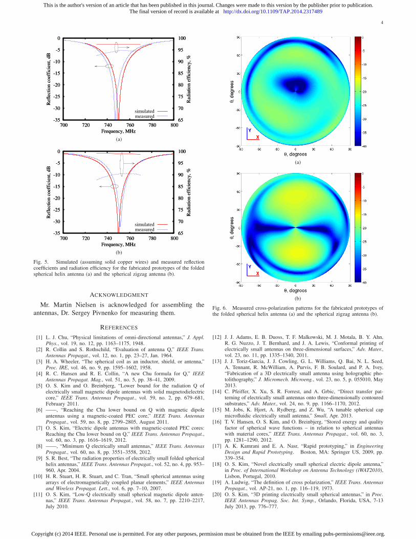
The radiation measurements were carried out at the DTU-
ESA Spherical Near-Field Antenna Test Facility. In particular,
the interest was to see if the antennas exhibited the expected
cross-polarization radiation patterns. It is observed in Fig. 6a
and 6b, where the measured cross-polarization component of
the respective radiation patterns for the folded spherical helix
antenna and spherical zigzag antenna are plotted, that the cross-
polarization for the former is omnidirectional, whereas the
latter yields a null in the XZ-plane, in full agreement with
the predictions (Fig. 2).
1These efficiencies can be obtained in simulations for antennas made of solidmetal wires with conductivity of about 5 · 10
6 S/m (Fig. 3). In this region ofconductivities, the spherical helix antenna is more efficient than the sphericalzigzag antenna.
supporting arcs
(a)
supporting arcs
(b)
Fig. 4. Fabricated prototypes of the folded spherical helix antenna (a) andthe spherical zigzag antenna (b). Supporting arcs are not coated with copper.
IV. CONCLUSION
A novel electrically small spherical zigzag antenna is pre-
sented and investigated both numerically and experimentally.
The antenna is of the electric dipole type, i.e., it radiates the
TM10 spherical mode, with characteristics very similar to those
of the well-known folded spherical helix antenna. The main
difference is in the cross-polarization pattern, which exhibits a
null in the antenna symmetry plane.
It is also shown that the modern rapid prototyping tech-
nology can be successfully applied for quick fabrication of
electrically small wire antennas. The test results presented
for the folded spherical helix antenna and spherical zigzag
antenna illustrate that the selective laser sintering is able to
reproduce fine wire structures with sufficient accuracy. The
subsequent conductive coating of the printed dielectric models
requires special attention, as electrically small antennas are
very sensitive to the dissipation losses in their structures. It
was found that coating with polycrystalline copper resulted in
a much better radiation efficiency of the antennas compared to
coating with conductive copper paint. The measurement results
for both fabricated antenna prototypes are in good agreement
with the predictions.
This is the author's version of an article that has been published in this journal. Changes were made to this version by the publisher prior to publication.The final version of record is available at http://dx.doi.org/10.1109/TAP.2014.2317489
Copyright (c) 2014 IEEE. Personal use is permitted. For any other purposes, permission must be obtained from the IEEE by emailing [email protected].
4
-35
-30
-25
-20
-15
-10
-5
0
700 720 740 760 780 800 65
70
75
80
85
90
95
100
Ref
lect
ion
co
effi
cien
t, d
B
Rad
iati
on
eff
icie
ncy
, %
Frequency, MHz
simulatedmeasured
-35
-30
-25
-20
-15
-10
-5
0
700 720 740 760 780 800 65
70
75
80
85
90
95
100
Ref
lect
ion
co
effi
cien
t, d
B
Rad
iati
on
eff
icie
ncy
, %
Frequency, MHz
(a)
-35
-30
-25
-20
-15
-10
-5
0
700 720 740 760 780 800 65
70
75
80
85
90
95
100
Ref
lect
ion
co
effi
cien
t, d
B
Rad
iati
on
eff
icie
ncy
, %
Frequency, MHz
simulatedmeasured
-35
-30
-25
-20
-15
-10
-5
0
700 720 740 760 780 800 65
70
75
80
85
90
95
100
Ref
lect
ion
co
effi
cien
t, d
B
Rad
iati
on
eff
icie
ncy
, %
Frequency, MHz
(b)
Fig. 5. Simulated (assuming solid copper wires) and measured reflectioncoefficients and radiation efficiency for the fabricated prototypes of the foldedspherical helix antenna (a) and the spherical zigzag antenna (b).
ACKNOWLEDGMENT
Mr. Martin Nielsen is acknowledged for assembling the
antennas, Dr. Sergey Pivnenko for measuring them.
REFERENCES
[1] L. J. Chu, “Physical limitations of omni-directional antennas,” J. Appl.
Phys., vol. 19, no. 12, pp. 1163–1175, 1948.[2] R. Collin and S. Rothschild, “Evaluation of antenna Q,” IEEE Trans.
Antennas Propagat., vol. 12, no. 1, pp. 23–27, Jan. 1964.[3] H. A. Wheeler, “The spherical coil as an inductor, shield, or antenna,”
Proc. IRE, vol. 46, no. 9, pp. 1595–1602, 1958.[4] R. C. Hansen and R. E. Collin, “A new Chu formula for Q,” IEEE
Antennas Propagat. Mag., vol. 51, no. 5, pp. 38–41, 2009.[5] O. S. Kim and O. Breinbjerg, “Lower bound for the radiation Q of
electrically small magnetic dipole antennas with solid magnetodielectriccore,” IEEE Trans. Antennas Propagat., vol. 59, no. 2, pp. 679–681,February 2011.
[6] ——, “Reaching the Chu lower bound on Q with magnetic dipoleantennas using a magnetic-coated PEC core,” IEEE Trans. Antennas
Propagat., vol. 59, no. 8, pp. 2799–2805, August 2011.[7] O. S. Kim, “Electric dipole antennas with magnetic-coated PEC cores:
Reaching the Chu lower bound on Q,” IEEE Trans. Antennas Propagat.,vol. 60, no. 3, pp. 1616–1619, 2012.
[8] ——, “Minimum Q electrically small antennas,” IEEE Trans. Antennas
Propagat., vol. 60, no. 8, pp. 3551–3558, 2012.[9] S. R. Best, “The radiation properties of electrically small folded spherical
helix antennas,” IEEE Trans. Antennas Propagat., vol. 52, no. 4, pp. 953–960, Apr. 2004.
[10] H. R. Stuart, H. R. Stuart, and C. Tran, “Small spherical antennas usingarrays of electromagnetically coupled planar elements,” IEEE Antennas
and Wireless Propagat. Lett., vol. 6, pp. 7–10, 2007.[11] O. S. Kim, “Low-Q electrically small spherical magnetic dipole anten-
nas,” IEEE Trans. Antennas Propagat., vol. 58, no. 7, pp. 2210–2217,July 2010.
(a)
(b)
Fig. 6. Measured cross-polarization patterns for the fabricated prototypes ofthe folded spherical helix antenna (a) and the spherical zigzag antenna (b).
[12] J. J. Adams, E. B. Duoss, T. F. Malkowski, M. J. Motala, B. Y. Ahn,R. G. Nuzzo, J. T. Bernhard, and J. A. Lewis, “Conformal printing ofelectrically small antennas on three-dimensional surfaces,” Adv. Mater.,vol. 23, no. 11, pp. 1335–1340, 2011.
[13] J. J. Toriz-Garcia, J. J. Cowling, G. L. Williams, Q. Bai, N. L. Seed,A. Tennant, R. McWilliam, A. Purvis, F. B. Soulard, and P. A. Ivey,“Fabrication of a 3D electrically small antenna using holographic pho-tolithography,” J. Micromech. Microeng., vol. 23, no. 5, p. 055010, May2013.
[14] C. Pfeiffer, X. Xu, S. R. Forrest, and A. Grbic, “Direct transfer pat-terning of electrically small antennas onto three-dimensionally contouredsubstrates,” Adv. Mater., vol. 24, no. 9, pp. 1166–1170, 2012.
[15] M. Jobs, K. Hjort, A. Rydberg, and Z. Wu, “A tunable spherical capmicrofluidic electrically small antenna,” Small, Apr. 2013.
[16] T. V. Hansen, O. S. Kim, and O. Breinbjerg, “Stored energy and qualityfactor of spherical wave functions – in relation to spherical antennaswith material cores,” IEEE Trans. Antennas Propagat., vol. 60, no. 3,pp. 1281–1290, 2012.
[17] A. K. Kamrani and E. A. Nasr, “Rapid prototyping,” in Engineering
Design and Rapid Prototyping. Boston, MA: Springer US, 2009, pp.339–354.
[18] O. S. Kim, “Novel electrically small spherical electric dipole antenna,”in Proc. of International Workshop on Antenna Technology (iWAT2010),Lisbon, Portugal, 2010.
[19] A. Ludwig, “The definition of cross polarization,” IEEE Trans. Antennas
Propagat., vol. AP-21, no. 1, pp. 116–119, 1973.[20] O. S. Kim, “3D printing electrically small spherical antennas,” in Proc.
IEEE Antennas Propag. Soc. Int. Symp., Orlando, Florida, USA, 7-13July 2013, pp. 776–777.
This is the author's version of an article that has been published in this journal. Changes were made to this version by the publisher prior to publication.The final version of record is available at http://dx.doi.org/10.1109/TAP.2014.2317489
Copyright (c) 2014 IEEE. Personal use is permitted. For any other purposes, permission must be obtained from the IEEE by emailing [email protected].