Designing Solar Thermal Systems for Selected Industrial ... · The SO-PRO Design Guide Structure...
21
© Fraunhofer ISE Designing Solar Thermal Systems for Selected Industrial Applications Stefan Hess Fraunhofer Institute for Solar Energy Systems ISE International Training Seminar Solar Process Heat (So-Pro) Intersolar Europe, 9 June 2011 www.ise.fraunhofer.de © Fraunhofer ISE Agenda Background and motivation The SO-PRO Design Guide Structure and application of the guide Important terms and values Holistic planning approach Example: System design for a washing process Pre-dimensioning with rules of thumb Making use of simulated nomograms Explanation of the other system designs and processes Exercises: Teamwork and discussion of results Summary 2
Transcript of Designing Solar Thermal Systems for Selected Industrial ... · The SO-PRO Design Guide Structure...

© Fraunhofer ISE
Designing Solar Thermal Systems for Selected Industrial Applications
Stefan Hess
Fraunhofer Institute for Solar Energy Systems ISE
International Training Seminar Solar Process Heat (So-Pro)Intersolar Europe, 9 June 2011
www.ise.fraunhofer.de
© Fraunhofer ISE
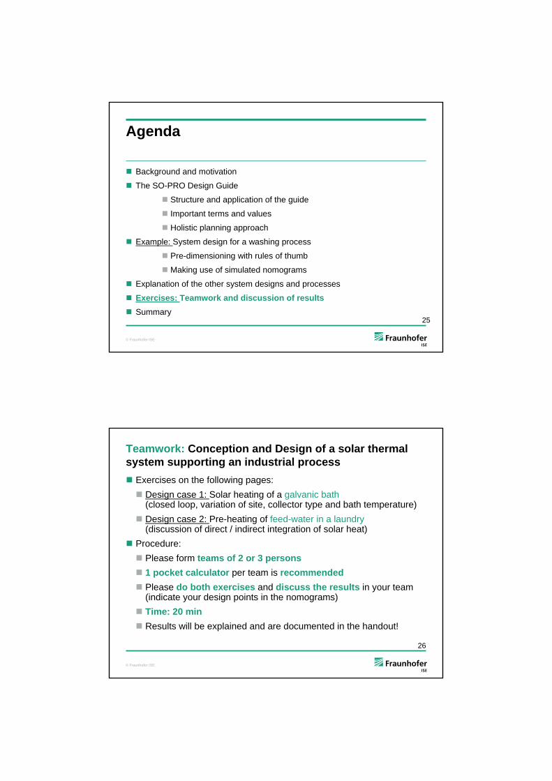
Agenda
Background and motivation
The SO-PRO Design Guide
Structure and application of the guide
Important terms and values
Holistic planning approach
Example: System design for a washing process
Pre-dimensioning with rules of thumb
Making use of simulated nomograms
Explanation of the other system designs and processes
Exercises: Teamwork and discussion of results
Summary2

© Fraunhofer ISE
Agenda
Background and motivation
The SO-PRO Design Guide
Structure and application of the guide
Important terms and values
Holistic planning approach
Example: System design for a washing process
Pre-dimensioning with rules of thumb
Making use of simulated nomograms
Explanation of the other system designs and processes
Exercises: Teamwork and discussion of results
Summary3
© Fraunhofer ISE
Industrial process heat: demand and potential
Demand per temperature range (Germany) [1]
Industrial process heat accounts for more than 20 % of the final energy demand (in Germany, similar for EU 25)
A significant share of 33 % is needed at temperatures below 150 °C
Huge potential:
Germany: ca. 16 TWh(3,1 % of industrial heat demand) = 36 Mio. m2 (450 kWh / (m2*a)) [1]
EU 25: ca. 70 TWh= 155 Mio. m2 [1](overall installed collector area in EU 27, 2009: ca. 46 Mio. m2 [2])
unter 100°C
23%
100°C..150°C
10%
150°C..250°C5%
über 250°C
62%
[1] C. Lauterbach et al. 2010: Potential of Solar Process Heat in Germany. Uni Kassel[2] W. Weiß et al., 2011: Solar Heat Worldwide Report 2009. AEE INTEC 4

© Fraunhofer ISE
Obstacles:
Financial restrictions (payback < 5 years)
Complex system integration, high planning effort, lack of standardized solutions, “missing links” between industrial process planners, energy consultants and solar companies
Priority of energy efficiency measures
Reality and obstacles
In 2010 only about 200 solar process heat systems ( ca. 42 MWth or 60.000 m2) in operation were reported worldwide (incl. space heating) [3].
But solar thermal process heat shows remarkable growth rates especially in China, India, Middle East and Austria [2].
Source: Sotec Solar, Germany
[3] W. Weiß, 2010: Speech at Intersolar Conference Solar Process Heat. IEA Task 33/IV and research of AEE INTEC 5
© Fraunhofer ISE
Agenda
Background and motivation
The SO-PRO Design Guide
Structure and application of the guide
Important terms and values
Holistic planning approach
Example: System design for a washing process
Pre-dimensioning with rules of thumb
Making use of simulated nomograms
Explanation of the other system designs and processes
Exercises: Teamwork and discussion of results
Summary6

© Fraunhofer ISE
[4] S. Heß et al. 2010: www.solar-process-heat.eu/guide
SO-PRO Design Guide [4]
Objective: provide „missing links“between process planners, energy consultants and solar companies
Design principles for four selected applications:
Heating of hot water for washing or cleaning
Heating of make-up water for open steam networks
Heating of baths or vessels
Convective drying with hot air
Holistic planning approach with consecutive steps
7
© Fraunhofer ISE
Important terms and values
Heat demand:
Thermal load: demand per day or year
Load profile: daily, weekly and annual variation of the heat demand
Available temperature level: temperature level at the heat integration point (low temperatures are often favorable)
Support of open or closed processes: A process is open, if the medium to be heated is not circulated.
Directly or indirectly heated processes: Heat supply to the process via heat exchanger is indirect. The supply is direct, when the heat carrier is consumed by the process.
Integration on process- or supply level: On the process level the solar heat is supporting a process, on the supply level the ST-system is supporting a hot water or steam network.
8
Source: Fraunhofer ISE
© Fraunhofer ISE
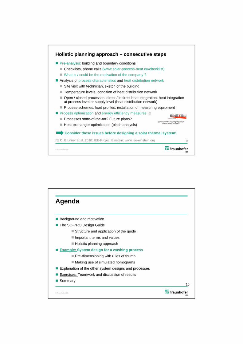
Holistic planning approach – consecutive steps
Pre-analysis: building and boundary conditions
Checklists, phone calls (www.solar-process-heat.eu/checklist)
What is / could be the motivation of the company ?
Analysis of process characteristics and heat distribution network
Site visit with technician, sketch of the building
Temperature levels, condition of heat distribution network
Open / closed processes, direct / indirect heat integration, heat integration at process level or supply level (heat distribution network)
Process-schemes, load profiles, installation of measuring equipment
Process optimization and energy efficiency measures [5]
Processes state-of-the-art? Future plans?
Heat exchanger optimization (pinch analysis)
Consider these issues before designing a solar thermal system!
[5] C. Brunner et al. 2010: IEE-Project Einstein: www.iee-einstein.org 9
© Fraunhofer ISE
Agenda
Background and motivation
The SO-PRO Design Guide
Structure and application of the guide
Important terms and values
Holistic planning approach
Example: System design for a washing process
Pre-dimensioning with rules of thumb
Making use of simulated nomograms
Explanation of the other system designs and processes
Exercises: Teamwork and discussion of results
Summary10

© Fraunhofer ISE
a) Heating of water for washing or cleaning
Exemplary system concept for pre-heating of hot water
cold water supply 15 °C
hot water 60 °Csolar thermal system
backup heating
tanksolar buffer
storage tank
boiler
11
© Fraunhofer ISE
Thermal load profile
Example for the discontinuous load profile of the hot water demand for cleaning of production equipment in a medium-sized company.
Two shifts (5:30 am to 10 pm)
High demand within the last two hours
No work at weekends, company holidays in summer and around the turn of the year
working day
0
20
40
60
80
100
120
0 2 4 6 8 10 12 14 16 18 20 22 24time of day
he
at d
em
an
d [
% ]
working week
0
20
40
60
80
100
120
0 1 2 3 4 5 6 7day of week
he
at d
em
an
d [
% ]
year
0
20
40
60
80
100
120
0 5 10 15 20 25 30 35 40 45 50week of year
he
at d
em
an
d [
% ]
12

© Fraunhofer ISE
Example: thermal load and annual heat demand
For a measured demand of 10 m3 hot water per working day the heat demand Qworking day can be calculated (simplified):
The load profile shows, that between 05:30 and 20:00 the hot water demand is about 408 l / h. Within the last two hours it is 2040 l / h.
Weekends and company holidays (235 working days out ot 365) lead to a mean daily demand of 6,44 m3 per day and an annual energy demand of thisprocess of 122,8 MWhth / year.
Which part of this annual demand can be covered by solar thermal in a reasonable way?
kWhkWh
kJK
Kkg
kJkgTcmQ pdayWorkingdayWorking 5.5223600/)4518.4000,10(
13
© Fraunhofer ISE
Pre-dimensioning (rules of thumb for Central Europe)
Aperture area AAp:
Method a): Roof area available as collector aperture area multiplied by estimated solar gains of 500 kWh / (year * m2
Ap)
Method b): Annual thermal energy demand of the processes to be supported by solar multiplied by a solar fraction of 40 %, divided by 500 kWh / (year * m2
Ap)
Storage volume VSto:
As a first indication, 50 lSto / m2Ap can be assumed:
222 100500/)4.08.122(500/)4.0( ApApAp
YearAp mm
kWhMWh
m
kWhQA
32
22 55010050 m
m
lm
m
lAV
ApApApSto
14
© Fraunhofer ISE
Simulated nomograms for system design
0
10
20
30
40
50
60
70
80
0 25 50 75 100 125 150 175 200
utilisation ratio [liter cleaning water / (day * m2Ap)]
sola
r fr
act
ion
[%]
0
100
200
300
400
500
600
700
800
sola
r sy
ste
m g
ain
s [k
Wh
/ (y
ear*
m2 A
p)]
10 liter storage vol. / m²Ap
30 liter storage vol. / m²Ap
50 liter storage vol. / m²Ap
70 liter storage vol. / m²Ap
Würzburg:Total horizontal radiation = 1090 kWh / (year* m²)
solar fractionsolar gains
36
515
Discont. load profile slide 13, 15 °C to 60 °C, flat-plate stratified storage, collector slope 35 °
15
Small systemsLarge systems
© Fraunhofer ISE
Results for this green design:
Calculation of the resulting collector aperture area by using the utilization ratio of 75 l hot water per day and m2
Ap:
The resulting solar system gains are valid for a storage volume of:
Calculation of the annual solar gains of this system by using:
specific system gains:
solar fraction:
22 86)
*75(/)440,6( Ap
ApAp m
mday
WWl
day
WWlA
lmm
lV Ap
ApSto 300,486*50 2
2
year
MWhm
myear
kWhE Ap
Apyear 3.4486*
*515 2
2
year
MWh
year
MWhE year 2.44%36*8.122
16
© Fraunhofer ISE
Variation: A “smaller” system?
0
10
20
30
40
50
60
70
80
0 25 50 75 100 125 150 175 200
utilisation ratio [liter cleaning water / (day * m2Ap)]
sola
r fr
act
ion
[%]
0
100
200
300
400
500
600
700
800
sola
r sy
ste
m g
ain
s [k
Wh
/ (y
ear*
m2 A
p)]
10 liter storage vol. / m²Ap
30 liter storage vol. / m²Ap
50 liter storage vol. / m²Ap
70 liter storage vol. / m²Ap
Würzburg:Total horizontal radiation = 1090 kWh / (year* m²)
solar fractionsolar gains
Discont. load profile slide 13, 15 °C to 60 °C, flat-plate stratified storage, collector slope 35 °
36
515
530
27
86 m2 64 m2
Example: demand = 6,440 l / day
17
© Fraunhofer ISE
0
10
20
30
40
50
60
70
80
90
100
0 25 50 75 100 125 150 175 200
utilisation ratio [liter cleaning water / (day * m2Ap)]
sola
r fr
act
ion
[%]
200
400
600
800
1000
1200
sola
r sy
ste
m g
ain
s [k
Wh
/ (y
ear*
m2 A
p)]
10 liter storage vol. / m²Ap 30 liter storage vol. / m²Ap
50 liter storage vol. / m²Ap 70 liter storage vol. / m²Ap
Madrid:Total horizontal radiation = 1615 kWh / (year* m²)
solar fractionsolar gains
Location Madrid
53
1015
64 m2
Example: demand = 6,440 l / day
18
© Fraunhofer ISE
Agenda
Background and motivation
The SO-PRO Design Guide
Structure and application of the guide
Important terms and values
Holistic planning approach
Example: System design for a washing process
Pre-dimensioning with rules of thumb
Making use of simulated nomograms
Explanation of the other system designs and processes
Exercises: Teamwork and discussion of results
Summary19
© Fraunhofer ISE
b) Pre-heating of make-up water
High solar gains because of low temperature level
System concept very similar to conventional systems for hot water
Only applicable to (partly) open steam networks
Heat recovery has to be analyzed (available temperature can rise)
demineralized cold water 20 °C
steam to processes
condensate return flow
steam for degasifi-cation
solar thermal system
storage
steam boiler
feed water
feed water tank 90 °C
solar buffer
storage tank
make-up water
Exemplary system concept for pre-heating the make-up water of a steam process
20

© Fraunhofer ISE
Thermal load profile
working day
0
20
40
60
80
100
120
0 2 4 6 8 10 12 14 16 18 20 22 24time of day
he
at
dem
an
d [ %
]
working week
0
20
40
60
80
100
120
0 1 2 3 4 5 6 7day of week
hea
t de
ma
nd
[ %
]
year
0
20
40
60
80
100
120
0 5 10 15 20 25 30 35 40 45 50
week of year
hea
t de
man
d [
% ]
Example for the make-up water consumption profile of a partly open steam network in a small laundry.
Two shifts (5:30 am to 10 pm), weekend, no company holidays
The fill-level control of the feed-water tank opens for intervals of 30 min
21
© Fraunhofer ISE
c) Heating of baths and vessels
Closed process: Economics highly depend on the bath temperature
Heat recovery from baths with higher temperatures checked?
Regular refill favorable
Small buffer storage volume possible (bath can act as a storage)
Exemplary system concept for the solar heating of an industrial bath. Direct heating of the bath possible by bypassing the storage. The electrical heater is used for temperature control.
raw parts
convective heat losses
65 °C
solar thermal system
storage
boiler
outlet 70 °C
inlet 90 °C
heater
solar buffer
storage tank
treated parts
22

© Fraunhofer ISE
Thermal load profile
Example for the continuous heat demand of an galvanic bath in a smaller company
Electrolyte has to be kept at a certain temperature all the time
Heat demand at night and at weekends to compensate heat losses
No work at weekends, no company holidays
working day
0
20
40
60
80
100
120
0 2 4 6 8 10 12 14 16 18 20 22 24time of day
he
at d
em
an
d [
% ]
working week
0
20
40
60
80
100
120
0 1 2 3 4 5 6 7day of week
he
at d
em
an
d [
% ]
year
0
20
40
60
80
100
120
0 5 10 15 20 25 30 35 40 45 50week of year
he
at d
em
an
d [
% ]
23
© Fraunhofer ISE
d) Convective drying with hot air
No storage necessary
Continuous heat demand favorable
Efficiency of air collectors decreases with decreasing mass flow
Exemplary system concept of an open drying process. The open air collector system is serially supported by a boiler (solar fan left, conventional fan right)
ambient air
hot air for drying 40 °C
air collector array
air / water heat exchanger
boilerboiler
24
© Fraunhofer ISE
Agenda
Background and motivation
The SO-PRO Design Guide
Structure and application of the guide
Important terms and values
Holistic planning approach
Example: System design for a washing process
Pre-dimensioning with rules of thumb
Making use of simulated nomograms
Explanation of the other system designs and processes
Exercises: Teamwork and discussion of results
Summary25
© Fraunhofer ISE
Teamwork: Conception and Design of a solar thermal system supporting an industrial process
Exercises on the following pages:
Design case 1: Solar heating of a galvanic bath (closed loop, variation of site, collector type and bath temperature)
Design case 2: Pre-heating of feed-water in a laundry (discussion of direct / indirect integration of solar heat)
Procedure:
Please form teams of 2 or 3 persons
1 pocket calculator per team is recommended
Please do both exercises and discuss the results in your team (indicate your design points in the nomograms)
Time: 20 min
Results will be explained and are documented in the handout!
26

© Fraunhofer ISE
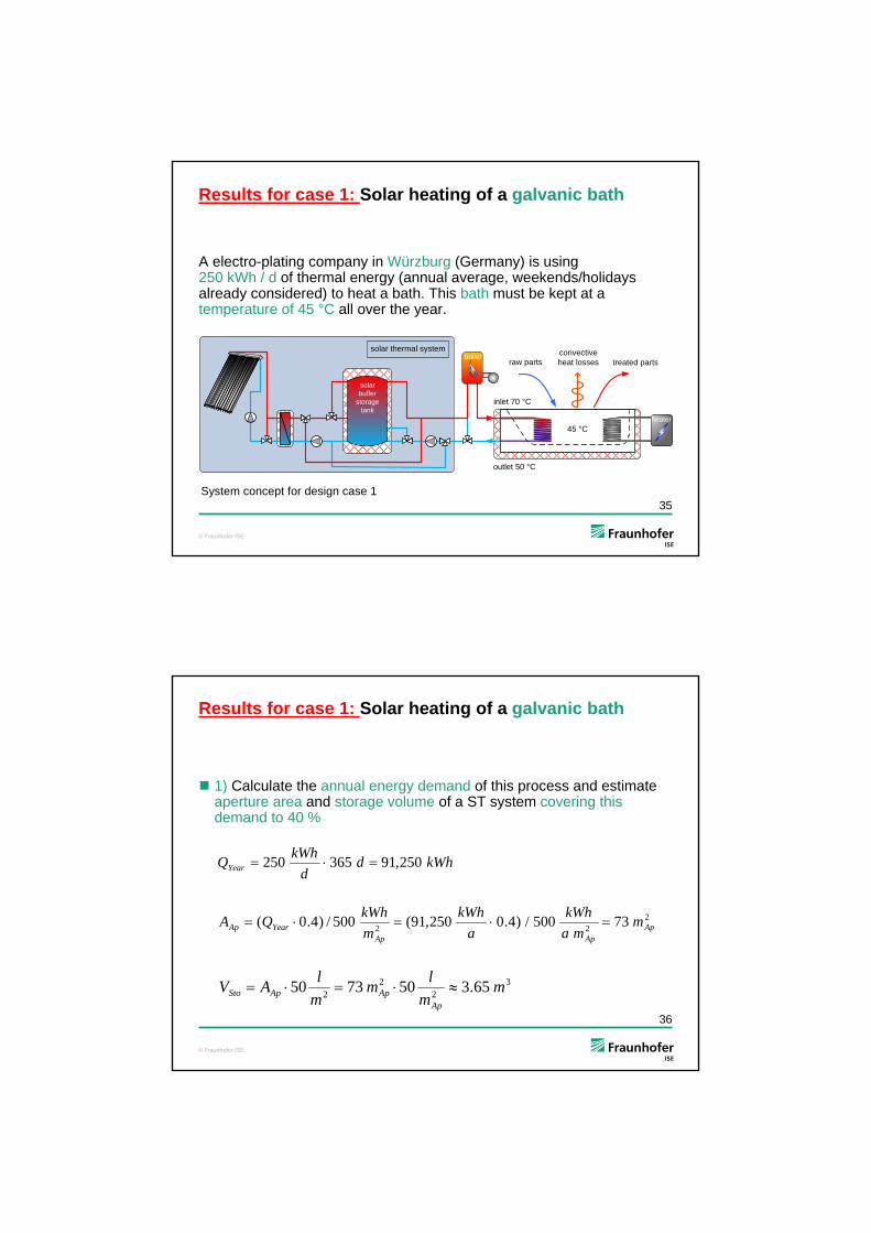
Design case 1: Solar heating of a galvanic bath
27
A electro-plating company in Würzburg (Germany) is using 250 kWh / d of thermal energy (annual average, weekends/holidays already considered) to heat a bath. This bath must be kept at a temperature of 45 °C all over the year.
raw partsconvective heat losses
45 °C
solar thermal system
storage
boiler
outlet 50 °C
inlet 70 °C
heater
solar buffer
storage tank
treated parts
System concept for design case 1
© Fraunhofer ISE
Design case 1: Solar heating of a galvanic bath
1) Calculate the annual energy demand of this process and estimate aperture area and storage volume of a ST system covering this demand to 40 % (compare slide 14)
222 73500/)4.0250,91(500/)4.0( ApApAp
YearAp mma
kWh
a
kWh
m
kWhQA
32
22 65.3507350 m
m
lm
m
lAV
ApApApSto
kWhdd
kWhQYear 250,91365250
28

© Fraunhofer ISE
Design case 1: Solar heating of a galvanic bath
2) Do a more accurate dimensioning of aperture area and storage volume based on the simulation results in the following nomogram. Apply vacuum tube collectors and 50 l / m2 storage. Which solar fraction should be selected?
0
10
20
30
40
50
60
70
80
90
100
0 1 2 3 4 5
specific thermal energy demand of bath [kWh / (day * m2Ap)]
sola
r fr
act
ion
[%]
0
100
200
300
400
500
sola
r sy
ste
m g
ain
s [k
Wh
/ (y
ear*
m2 A
p )]
50 liter storage vol. / m²Ap, flat-plate
70 liter storage vol. / m²Ap, flat-plate
50 liter storage vol. / m²Ap, evacuated-tube
70 liter storage vol. / m²Ap, evacuated-tube
Würzburg:Total horizontal radiation = 1090 kWh / (year*m²)
solar fractionsolar gains
%40solf
2
2
100
5.2
250
m
mdkWh
dkWh
AAp
3
22
5
50100
m
m
lmVSto
Bath temp.: 45 °C
29
© Fraunhofer ISE
0
10
20
30
40
50
60
70
80
90
100
0 1 2 3 4 5
specific thermal energy demand of bath [kWh / (day * m2Ap)]
sola
r fr
act
ion
[%]
0
100
200
300
400
500
sola
r sy
ste
m g
ain
s [k
Wh
/ (y
ear*
m2 A
p)]
30 liter storage vol. / m²Ap
50 liter storage vol. / m²Ap
70 liter storage vol. / m²Ap
Würzburg:Total horizontal radiation = 1090 kWh / (year*m²)
solar fractionsolar gains
Design case 1: Solar heating of a galvanic bath
3) How would you assess the same system with a bath temperature of 65 °C ? What is the main reason for the low solar gains? Look at the system concept on slide 22!
Reason: Available temperature level: 70 °C %25solf
2
2
100
5.2
250
m
mdkWh
dkWh
AAp
3
22
5
50100
m
m
lmVSto
Bath temp.: 65 °C, evacuated tubes
30
© Fraunhofer ISE
Design case 1: Solar heating of a galvanic bath
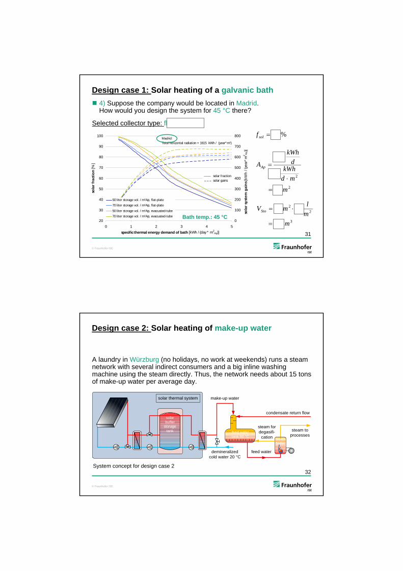
4) Suppose the company would be located in Madrid. How would you design the system for 45 °C there?
Selected collector type: flat-plate
%56solf
2
2
83
3
250
m
mdkWh
dkWh
AAp
3
22
8.5
7083
m
m
lmVSto
20
30
40
50
60
70
80
90
100
0 1 2 3 4 5
specific thermal energy demand of bath [kWh / (day * m2Ap)]
sola
r fr
act
ion
[%]
0
100
200
300
400
500
600
700
800
sola
r sy
ste
m g
ain
s [k
Wh
/ (y
ear*
m2 A
p )]
50 liter storage vol. / m²Ap, flat-plate
70 liter storage vol. / m²Ap, flat-plate
50 liter storage vol. / m²Ap, evacuated-tube
70 liter storage vol. / m²Ap, evacuated-tube
Madrid:Total horizontal radiation = 1615 kWh / (year*m²)
solar fractionsolar gains
Bath temp.: 45 °C
31
© Fraunhofer ISE
Design case 2: Solar heating of make-up water
A laundry in Würzburg (no holidays, no work at weekends) runs a steam network with several indirect consumers and a big inline washingmachine using the steam directly. Thus, the network needs about 15 tons of make-up water per average day.
32
demineralized cold water 20 °C
steam to processes
condensate return flow
steam for degasifi-cation
solar thermal system
storage
steam boiler
feed water
feed water tank 90 °C
solar buffer
storage tank
make-up water
System concept for design case 2

© Fraunhofer ISE
0
10
20
30
40
50
60
70
80
0 25 50 75 100 125 150 175 200
utilisation ratio [liter make-up water / (day * m2Ap)]
sola
r fr
act
ion
[%]
0
100
200
300
400
500
600
700
800
sola
r sy
ste
m g
ain
s [k
Wh
/ (y
ear*
m2 A
p)]
30 liter storage vol. / m²Ap
50 liter storage vol. / m²Ap
70 liter storage vol. / m²Ap
Würzburg:Total horizontal radiation = 1090 kWh / (year*m²)
solar fractionsolar gains
Design case 2: Solar heating of make-up water
1) Fill in the characteristic values for a medium-sized solar thermal system supporting this process (see indicated design)
%25solf
2
2
200
75
15000
m
mdl
dl
AAp
3
22
10
50200
m
m
lmVSto
33
flat plate collectors
© Fraunhofer ISE
Design case 2: Solar heating of make-up water
2) What is the difference in the recommended solar fraction and the solar system gains between make-up water (slide 33, load profile slide 21) and cleaning water (slide 15, load profile slide 12)?
a) Recommended solar fraction:
25 % for make-up water and 36 % for cleaning water
b) Solar system gains:
570 kWh / m2 for make-up water and 515 kWh / m2 for cleaning water
34
4) Which are the two main reasons for the different solar system gains?
a) The load profile for cleaning shows company holidays.
b) Solar gains above 60 °C can not be used for the cleaning water.
3) What is the reason for the different solar fraction?
The thermal load is defined up to 60 °C for cleaning water, but up to 90 °C for make-up water.
© Fraunhofer ISE
Results for case 1: Solar heating of a galvanic bath
35
A electro-plating company in Würzburg (Germany) is using 250 kWh / d of thermal energy (annual average, weekends/holidays already considered) to heat a bath. This bath must be kept at a temperature of 45 °C all over the year.
raw partsconvective heat losses
45 °C
solar thermal system
storage
boiler
outlet 50 °C
inlet 70 °C
heater
solar buffer
storage tank
treated parts
System concept for design case 1
© Fraunhofer ISE
Results for case 1: Solar heating of a galvanic bath
1) Calculate the annual energy demand of this process and estimate aperture area and storage volume of a ST system covering this demand to 40 %
222 73500/)4.0250,91(500/)4.0( ApApAp
YearAp mma
kWh
a
kWh
m
kWhQA
32
22 65.3507350 m
m
lm
m
lAV
ApApApSto
kWhdd
kWhQYear 250,91365250
36
© Fraunhofer ISE
Results for case 1: Solar heating of a galvanic bath
2) Do a more accurate dimensioning of aperture area and storage volume based on the simulation results in the following nomogram. Apply vacuum tube collectors and 50 l / m2 storage. Which solar fraction should be selected?
0
10
20
30
40
50
60
70
80
90
100
0 1 2 3 4 5
specific thermal energy demand of bath [kWh / (day * m2Ap)]
sola
r fr
act
ion
[%]
0
100
200
300
400
500
sola
r sy
ste
m g
ain
s [k
Wh
/ (y
ear*
m2 A
p )]
50 liter storage vol. / m²Ap, flat-plate
70 liter storage vol. / m²Ap, flat-plate
50 liter storage vol. / m²Ap, evacuated-tube
70 liter storage vol. / m²Ap, evacuated-tube
Würzburg:Total horizontal radiation = 1090 kWh / (year*m²)
solar fractionsolar gains
%40solf
2
2
100
5.2
250
m
mdkWh
dkWh
AAp
3
22
5
50100
m
m
lmVSto
Bath temp.: 45 °C
37
© Fraunhofer ISE
0
10
20
30
40
50
60
70
80
90
100
0 1 2 3 4 5
specific thermal energy demand of bath [kWh / (day * m2Ap)]
sola
r fr
act
ion
[%]
0
100
200
300
400
500
sola
r sy
ste
m g
ain
s [k
Wh
/ (y
ear*
m2 A
p)]
30 liter storage vol. / m²Ap
50 liter storage vol. / m²Ap
70 liter storage vol. / m²Ap
Würzburg:Total horizontal radiation = 1090 kWh / (year*m²)
solar fractionsolar gains
Results for case 1: Solar heating of a galvanic bath
3) How would you assess the same system with a bath temperature of 65 °C ? What is the main reason for the low solar gains? Look at the system concept on slide 22!
Reason: Available temperature level: 70 °C %25solf
2
2
100
5.2
250
m
mdkWh
dkWh
AAp
3
22
5
50100
m
m
lmVSto
Bath temp.: 65 °C, evacuated tubes
38

© Fraunhofer ISE
Results for case 1: Solar heating of a galvanic bath
4) Suppose the company would be located in Madrid. How would you design the system for 45 °C there?
Selected collector type: flat-plate
%56solf
2
2
83
3
250
m
mdkWh
dkWh
AAp
3
22
8.5
7083
m
m
lmVSto
20
30
40
50
60
70
80
90
100
0 1 2 3 4 5
specific thermal energy demand of bath [kWh / (day * m2Ap)]
sola
r fr
act
ion
[%]
0
100
200
300
400
500
600
700
800
sola
r sy
ste
m g
ain
s [k
Wh
/ (y
ear*
m2 A
p )]
50 liter storage vol. / m²Ap, flat-plate
70 liter storage vol. / m²Ap, flat-plate
50 liter storage vol. / m²Ap, evacuated-tube
70 liter storage vol. / m²Ap, evacuated-tube
Madrid:Total horizontal radiation = 1615 kWh / (year*m²)
solar fractionsolar gains
Bath temp.: 45 °C
39
© Fraunhofer ISE
Results for case 2: Solar heating of make-up water
A laundry in Würzburg (no holidays, no work at weekends) runs a steam network with several indirect consumers and a big inline washingmachine using the steam directly. Thus, the network needs about 15 tons of make-up water per average day.
40
demineralized cold water 20 °C
steam to processes
condensate return flow
steam for degasifi-cation
solar thermal system
storage
steam boiler
feed water
feed water tank 90 °C
solar buffer
storage tank
make-up water
System concept for design case 2

© Fraunhofer ISE
0
10
20
30
40
50
60
70
80
0 25 50 75 100 125 150 175 200
utilisation ratio [liter make-up water / (day * m2Ap)]
sola
r fr
act
ion
[%]
0
100
200
300
400
500
600
700
800
sola
r sy
ste
m g
ain
s [k
Wh
/ (y
ear*
m2 A
p)]
30 liter storage vol. / m²Ap
50 liter storage vol. / m²Ap
70 liter storage vol. / m²Ap
Würzburg:Total horizontal radiation = 1090 kWh / (year*m²)
solar fractionsolar gains
Results for case 2: Solar heating of make-up water
1) Fill in the characteristic values for a medium-sized solar thermal system supporting this process (see indicated design)
%25solf
2
2
200
75
15000
m
mdl
dl
AAp
3
22
10
50200
m
m
lmVSto
41
flat plate collectors
© Fraunhofer ISE
Results for case 2: Solar heating of make-up water
2) What is the difference in the recommended solar fraction and the solar system gains between make-up water (slide 33, load profile slide 21) and cleaning water (slide 15, load profile slide 12)?
a) Recommended solar fraction:
25 % for make-up water and 36 % for cleaning water
b) Solar system gains:
570 kWh / m2 for make-up water and 515 kWh / m2 for cleaning water
42
4) Which are the two main reasons for the different solar system gains?
a) The load profile for cleaning shows company holidays.
b) Solar gains above 60 °C can not be used for the cleaning water.
3) What is the reason for the different solar fraction?
The thermal load is defined up to 60 °C for cleaning water, but up to 90 °C for make-up water.