Tools for Designing Thermal Management of … for Designing Thermal Management of Batteries in...
31
NREL is a national laboratory of the U.S. Department of Energy, Office of Energy Efficiency and Renewable Energy, operated by the Alliance for Sustainable Energy, LLC. Tools for Designing Thermal Management of Batteries in Electric Drive Vehicles Ahmad Pesaran, Ph.D. Matt Keyser, Gi-Heon Kim, Shriram Santhanagopalan, Kandler Smith National Renewable Energy Laboratory Golden, Colorado Presented at the Large Lithium Ion Battery Technology & Application Symposia Advanced Automotive Battery Conference Pasadena, CA • February 4-8, 2013 NREL/PR-5400-57747
Transcript of Tools for Designing Thermal Management of … for Designing Thermal Management of Batteries in...

NREL is a national laboratory of the U.S. Department of Energy, Office of Energy Efficiency and Renewable Energy, operated by the Alliance for Sustainable Energy, LLC.
Tools for Designing Thermal Management of Batteries in Electric Drive Vehicles
Ahmad Pesaran, Ph.D. Matt Keyser, Gi-Heon Kim, Shriram Santhanagopalan, Kandler Smith National Renewable Energy Laboratory Golden, Colorado
Presented at the Large Lithium Ion Battery Technology & Application Symposia
Advanced Automotive Battery Conference Pasadena, CA • February 4-8, 2013
NREL/PR-5400-57747

2
Battery Temperature in xEVs • Lithium-ion battery (LIB) technology is expected to be the
energy storage of choice for electric drive vehicles (xEVs) in the coming years
• Temperature has a significant impact on life, performance, safety, and cost of LIBs
Dictates power capability through cold cranking
Also limits the electric driving range
Dictates the size depending on the power and energy
fade rate
Limiting power to reduced T increase and
degradation
Kandler Smith, NREL Milestone Report, 2008
Desired Operating
Temperature

3
Battery Thermal Management for xEVs • Higher temperatures degrade LIBs more quickly, while low
temperatures reduce power and energy capabilities, resulting in cost, reliability, safety, range, or drivability implications
• Therefore, battery thermal management is needed for xEVs to: o Keep the cells in the desired temperature range o Minimize cell-to-cell temperature variations o Prevent the battery from going above or below acceptable limits o Maximize useful energy from cells and pack o Use little energy for operation
• However, a battery thermal management systems (BTMS) could: o Increase complexity o Add cost o Reduce reliability o Consume energy for operation o …

4
Battery Thermal Management System
• Most in the xEV battery community agree that the value that a BTMS provides in increasing battery life and improving performance outweighs its additional cost and complexity
• However, the BTMS needs to be designed appropriately with the right tools
• The National Renewable Energy Laboratory has been a leader in battery thermal analysis and characterization for aiding industry to design improved BTMSs
• This presentation describes the tools that NREL has used and that we believe are needed to design properly sized BTMSs
5
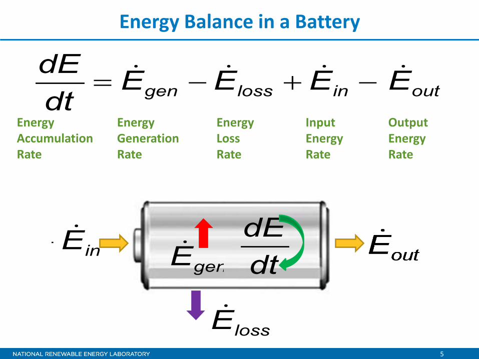
Energy Balance in a Battery
outinlossgen EEEEdtdE −+−=
Energy Accumulation Rate
Energy Generation Rate
Energy Loss Rate
Input Energy Rate
Output Energy Rate
inE+genE dt
dE
lossE−

6
Heat Transfer in a Battery (Assumption: isothermal ~ very high thermal conductivity)
• Electrochemical reactions • Phase changes • Mixing effects • Joule heating
conductionExtasasgensp QTTAeTThAHeat
dtdTmC _
44 )()( −−−−−= δ
Rate of Temp Change
Rate of Internal Heat Generation
Convection Heat Rate
Radiation Heat Rate
Conduction Heat Rate
conductionExtasas QTTAeTThA _44 )()( +−+− δ
genHeatsp
dtdTmC
Heat generated ( ) in a battery consists of:
Method of heat rejection/addition for thermal control a
s
TT = Battery Temp
= Ambient Temp
genHeat

7
Heat Generation Rate and Specific Heat Impact Battery Temperature Rise
0
2
4
6
8
10
12
14
16
0 400 800 1200 1600 2000
Time (seconds)
Tem
pera
ture
Ris
e (D
egre
e C
)
2C Rate (4.45 W/cell) Cp=1019 J/kg/CC/1Rate (1.33 W/Cell) Cp = 1019 J/kg/C2C Rate (4.45 W/Cell) Cp = 707 J/kg/C
Slow discharge
Fast discharge
Assuming uniform battery temperature and the same heat transfer coefficient for three cases

8
Lnt
THCTTeTThnnk
.0
BBBp,B
44ssn )()( )T( =
∞∞ ∂∂
+−+−=∂
∂− ρδ
Heat Transfer in a Battery (Non-isothermal; case and core regions)
Core region
Case or boundary region
TkHeattTC genp ∇⋅∇+=∂∂ρ
tyconductivithermalk :
Heat flux from the core
Convection from various case surfaces
Radiation from various case surfaces
Heat accumulation in the case

9
Case + Core Example: T Distribution in a Module
Air CooledQ = 5 W/cellTt=0 = 30 oCTair = 25 oChair = 18 W/m2K
30
35
40
45
50
55
Max
. Cel
l Tem
pera
ture
[o C
]
0 10 20 30 40 50 60
Time [min]
Top
Middle
Bottom
Ttop,SS = 54 oC
Air-cooled 5 W/cell
h = 18 W/Km2
TSS= 54°C
A. Pesaran, A. Vlahinos, S. Burch. Proceedings of the 14th Electric Vehicle Symposium, December 1997

10
What Information is Needed to Design a BTMS? • Acceptable temperature range for cell components at all times, i.e.,
active material, binders, separators, electrolyte, etc. • Acceptable temperature difference within cells and from cell to cell,
depending on the chemistry and management system • Maximum and minimum temperature limits for life specifications,
performance ratings, and safety considerations • Thermo-physical properties of cells or components (density, specific
heat, directional thermal conductivities) • Heat generation rate under average and aggressive drive profiles and
loads for the specific electric drive • Heat rejection rate depending on thermal management strategy
o Fluid heat transfer coefficients or sink conductance o Cooling fluid flow rate and sink temperature
• Configurations and dimensions of cells and proposed BTMS • Parasitic power needed to push fluids/cooling through BTMS

11
Tools for Designing BTMS
• Experimental Tools o Isothermal calorimeters and battery testers o Infrared thermal imaging o Thermal conductivity meters o Heat transfer characterization setup o Battery thermal testing loop
• Modeling Tools
o First-order/lumped capacitance thermal and fluid models o 1-D and 2-D thermal and fluid-flow performance models o 1-D vehicle integrated thermal-flow models o 3-D electro-thermal models o 3-D electrochemical-thermal model o Computer-aided engineering software

12
Isothermal Battery Calorimeters • We use a single-ended (one test chamber) conduction
calorimeter to measure specific heat and heat generation at various current rates, temperatures, and states of charge (SOCs)
Sample/Module
Battery Tester
Initially fabricated by Calorimetry Sciences Corporation; later improved by NREL. A. Pesaran, M. Keyser, D. Russell, J. Crawford, E. Lewis. Presented at the Long Beach Battery Conference, January 1998

13
Heat
Rat
e (W
atts
)
Time (Hours)
NREL’s First Isothermal Battery Calorimeter • Heat flux measured between the sample and a heat sink using
heat flux gauges • The heat sink is kept at a constant temperature with a precise
isothermal bath
• Max module that could be tested: 21 cm x 20 cm x 32 cm • Heat rate detection: 0.015 W to 100 W • Minimum detectable heat effect: 15 J (at 25°C) • Baseline stability: ±10 mW • Temperature range: -30°C to 60°C (±0.001°C) • Accuracy of better than ±3%
Calorimeter response
Total heat generation = Area under each curve
Calorimeter Calorimeter Cavity Photo Credits: David Parson & Matt Keyser, NREL

14
0.0
5.0
10.0
15.0
20.0
25.0
30.0
35.0
40.0
45.0
50.0
0.0 20.0 40.0 60.0 80.0 100.0 120.0
Heat
Gen
erat
ion
(Wat
ts)
RMS Discharge Current (Amps)
Initial Temp = -15 C Initial Temp = 0 C Initial Temp = 30 C° ° °
Example Heat Generation Data for CC Discharge (from max to min allowable capacity-SOC)
22-Ah Li-Ion Cell

15
Specific Heat (Heat Capacity) • Can be estimated from constituents of cell/module
• Can be estimated using a calorimeter by measuring heat
lost/gained (Q) from the battery going from Tinitial to Tfinal o Heat capacity is calculated by
∑∑ •=n
ii
n
ipavep mmCC11
,, /)(
))(/(, finalinitialtotalavep TTmQC −•=
Cell/Module Taverage (°C)
Heat Capacity J/kg/°C
NiMH – 18 Ah 33.2 677
Li-Ion 18650 33.1 1,105
Li-Ion Pouch – 4 Ah 18 1,012
VRLA – 16.5 Ah 32 660
Ni Zn – 22 Ah 20 1,167
Thermal Characteristics of Selected EV and HEV Batteries, A. Pesaran, M. Keyser. Presented at the 16th Annual Battery Conference; Long Beach California, January 2001

16
NREL’s Large Volume Battery Calorimeter
• Single chamber, conduction, isothermal • Includes several patent-pending
concepts • Test chamber submerged • Capability to test liquid-cooled batteries • Safety features in case of events • Test chamber 6 times larger than the
NREL module calorimeter o 2 ft x 2 ft x 4 ft
• Heat Rate: 0.05 W to 4 kW • Accuracy of heat meas. ±3%
Test Chamber in Isothermal Bath
Test Chamber
Flux Gauges in Test Chamber
Completed System with Heating/Cooling Unit
Photo Credits: Dennis Schroder & Ahmad Pesaran, NREL

17
NREL’s New Isothermal Cell Calorimeter • Single chamber, conduction,
isothermal • Test chamber submerged
under isothermal bath • Testing chamber: 15 cm W x
10 cm L x 6 cm H • Heat detection limit: 1 mW
and 10 J • Initial testing shows excellent
baseline stability and an error of less than ±1.6%
• CRADA and license agreement signed with NETZSCH to commercialize NREL’s battery calorimeter design
http://www.nrel.gov/vehiclesandfuels/energystorage/pdfs/50558.pdf
Photo Credits: Dennis Schroder & Dirk Long, NREL

18
• Quickly finds thermal signature of the whole cell under electrical loads
• Helps understand thermal behavior, creates diagnostics, and improves designs
• Could be used as a validation of thermal models
• Thermal signature depends on several factors o Geometry, thermal conductivity of case and core,
location of terminals, design of interconnects, current density, current profile, chemistry, environment
• We spray a thin layer of boron nitride on all the surfaces of the face that needs to be imaged
• We minimize reflections from other objects by placing the cells in a non-reflective environment
• We usually test three cells to see the impact of power cable connected to the two end cells
Infrared Thermal Imaging
Thermal image of a 6.5-Ah NiMH module from a MY 2002 Prius under 100A CC discharge
Photo Credits: Matt Keyser, NREL

19
Examples of Battery Infrared Thermal Imaging
25°C 45°C
http://www.nrel.gov/vehiclesandfuels/energystorage/publications.html Photo Credits: Matt Keyser & Dirk Long, NREL

20
Thermal Conductivity Estimation & Measurement
Provided by Peter Ralbovsky - Netzsch Instruments
Measurement Techniques
• The core material (electrochemically activepart) is assumed to consist of a homogenousmaterial with average properties for resistivityand thermal conductivity, but with differentproperties in different directions(orthotropic xyz or rθZ)
• Usually case and core of a cellare considered two differentregions with different thermalconductivity
Can use finite element analysis to calculate the effective thermal conductivity in each direction
kx = q *∆x /∆T ky = q *∆y /∆T
or kz = q *∆z /∆T kr = q *∆r /∆T

21
Measuring Thermal Conductivity of LIB Components Flash Diffusivity Method: • Thermal diffusivity (α) is a measure of how quickly a material can
change its temperature when heat is applied• The temperature rise on the rear surface is measured in time using an
infrared detector ( ) ( ) ( ) ( )TTcTTK p ρα ⋅⋅=
Provided by Peter Ralbovsky, Netzsch Instruments
• Measurements have shown that generally the thermal conductivity of LIB is muchlower in-plane than cross-plane
Cross plane ~ 0.8 to 1.1 W/m/K In plane ~ 28 to 35 W/m/K
Netzsch LFA 447 Unit
Photo Credit: John Ireland, NREL

22
Battery Thermal Testing Loops • Measuring heat transfer coefficients or conductance
• Hardware in the loop thermal testing
Temp dist. in a USABC module
Photo Credits: Ahmad Pesaran
Photo Credits: Kandler Smith, NREL

23
Battery Thermal Responses
3D Component Analysis
System Analysis
Cell Characteristics
• Shape and size : Prismatic/Cylinder/Oval, etc. • Materials/Chemistries • Voltage/current & heat gen data • Thermal/Current Paths inside a Cell Module Cooling Strategy
• Coolant Type: Air/Liquid • Direct Contact/Jacket Cooling • Serial/Parallel Cooling • Terminal/Side Cooling • Module Shape/Dimensions • Coolant Path inside a Module • Coolant Flow Rate • Passive with phase change • etc.
• Temperature History Cells/Module/Pack • Temperature Distribution in a Cell • Cell-to-Cell Temperature Imbalance in a Module • Battery Performance Prediction • Pressure Prop and Parasitic Power • etc.
• Vehicle Driving Cycles • Control Strategy • Ambient Temperature • etc.
Operating Conditions
Design Process
Process for Battery Thermal Modeling

24
Lumped Capacitance Thermal Model for Vehicle Simulations
• For vehicle simulation, the thermal model needs to be linked to the battery model for temperature dependency
• A 2-node lumped thermal model (case + homogenous core) with simple heat convection is developed for ADVISOR vehicle simulator

25
Example of 2-D Module Thermal Modeling
Tmax = 44°C Delta Tcore = 9°C
Case 1. No holes and no air flow between cells
Tmax = 53°C Delta Tcore = 13°C
Cell core
Plastic case
Air gap
Case 2. With holes and air flow between cells
Photo Credits: David Parsons, NREL

26
Electro-Thermal Analysis Approach
Current Density
Temperature
• Capture details of a cell including non-electrochemical hardware with finite element analysis
• Estimate component resistances using geometry and materials
• Apply voltage drop to calculate current density in components
• Estimate resistive heating (I2R) in each component
• Apply electrochemical heat of reactions in the core (active parts)
• Apply heat transfer boundary conditions on cell exterior
• Predict temperature distribution in the cell from current density and related heat generation distribution

27
Example of 3-D Electro-Thermal Modeling
Design A Terminals on
each side
Design B Terminals on the
same side
16 Ah Power Cell
Temp Dist Design A
Design A Thermal Response
Design B Thermal Response
Under 110 A RMS load • The overall resistance of Cell
Design B is less than Cell Design A • Under the same current profile,
Cell Design B generates less heat and thus performs better thermally
Electro-thermal Analysis of Lithium Ion Batteries, Pesaran, A.; Vlahinos, A.; Bharathan, D. Proceedings of the 23rd International Battery Seminar, Fort Lauderdale, Florida. March 13-16, 2006.
Photo Credit: Ahmad Pesaran
28
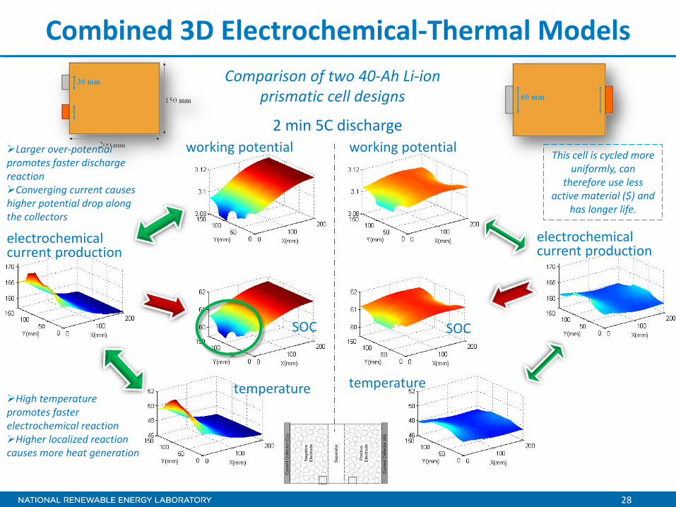
Combined 3D Electrochemical-Thermal Models Comparison of two 40-Ah Li-ion
prismatic cell designs
This cell is cycled more uniformly, can
therefore use less active material ($) and
has longer life.
2 min 5C discharge working potential working potential
electrochemical current production
temperature temperature
SOC SOC
electrochemical current production
High temperature promotes faster electrochemical reaction Higher localized reaction causes more heat generation
Larger over-potential promotes faster discharge reaction Converging current causes higher potential drop along the collectors
Cur
rent
Col
lect
or (C
u)
Cur
rent
Col
lect
or (A
l)
p
Neg
ativ
eE
lect
rode
Sep
arat
or
Pos
itive
Ele
ctro
de

29
Computer-Aided Engineering of Batteries (CAEBAT) • U.S. Department of Energy is
supporting development of electrochemical-thermal models and software design
• The objective is to shorten time and reduce cost for design and development of battery systems, including the design and analysis of BTMSs
• Other software design and analysis tools dealing with other physics may be incorporated in CAEBAT
Physics of Li-Ion Battery Systems in Different Length Scales
Li diffusion in solid phaseInterface physicsParticle deformation & fatigueStructural stability
Charge balance and transportElectrical network in composite electrodesLi transport in electrolyte phase
Electronic potential ¤t distributionHeat generation and transferElectrolyte wettingPressure distribution
Atomic Scale
Particle Scale
Electrode Scale Cell Scale
System ScaleSystem operating conditionsEnvironmental conditionsControl strategy
Module ScaleThermal/electricalinter-cell configurationThermal managementSafety controlThermodynamic properties
Lattice stabilityMaterial-level kinetic barrierTransport properties
Thermal-electrochemical response of a pack Courtesy of Christian Shaffer, EC Power-CAEBAT

30
Summary
• Battery thermal management needed for xEVs • Battery thermal management system needs to be optimized
with right tools for lowest cost • NREL has state-of-the art experimental and analytical tools for
analysis and design of battery thermal management systems • Experimental tools, such as the isothermal calorimeter, are
essential for obtaining data for generating input to design tools and eventually verifying the performance of the battery thermal management system
• Computer-aided engineering tools for the design of battery electrical and thermal management systems are now accessible to automotive and battery engineers

31
Acknowledgments • Support provided by the DOE Vehicle Technologies Program
o Dave Howell, Hybrid and Electric Systems Team Lead o Brian Cunningham, Energy Storage Technology Manager
• Feedback from CAEBAT Subcontract Technical Leads o Taeyoung Han (General Motors) o Steve Hartridge (CD-adapco) o Christian Shaffer (EC Power)
• Support from NREL Staff o John Ireland o Dirk Long o Mark Mihalic o Marissa Rusinek
nrel.gov/vehiclesandfuels/energystorage
Contact Information: Ahmad Pesaran
[email protected] 303-275-4441