Designing Patterns using Triangle- Quad Hybrid...
50
Designing Patterns using Triangle- Quad Hybrid Meshes CHI-HAN PENG (KAUST, Saudi Arabia)et al. SIGGRAPH 2018 Copyright of figures and other materials in the paper belongs original authors. Presented by Qi-Meng Zhang 2018. 10. 25 Computer Graphics @ Korea University
Transcript of Designing Patterns using Triangle- Quad Hybrid...

Designing Patterns using Triangle-Quad Hybrid Meshes
CHI-HAN PENG (KAUST, Saudi Arabia)et al.SIGGRAPH 2018
Copyright of figures and other materials in the paper belongs original authors.
Presented by Qi-Meng Zhang
2018. 10. 25
Computer Graphics @ Korea University
Qi-meng Zhang| 2018. 10. 25 | # 2Computer Graphics @ Korea University
Abstract
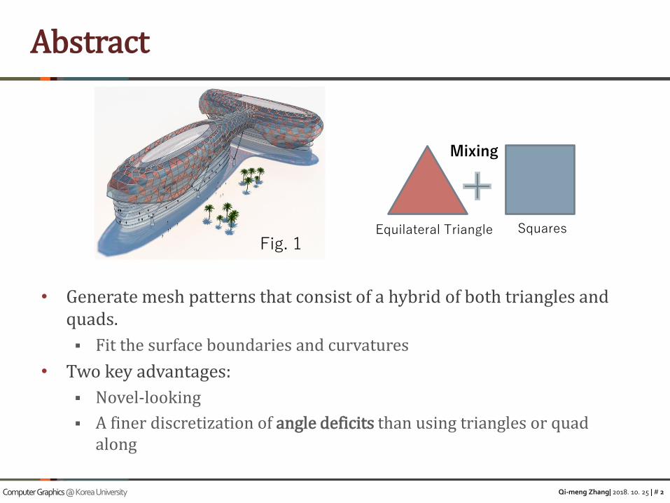
• Generate mesh patterns that consist of a hybrid of both triangles and quads.
▪ Fit the surface boundaries and curvatures
• Two key advantages:
▪ Novel-looking
▪ A finer discretization of angle deficits than using triangles or quad along
Fig. 1Equilateral Triangle Squares
Mixing

Qi-meng Zhang| 2018. 10. 25 | # 3Computer Graphics @ Korea University
• Motivation
▪ Large body of research studying the meshing of surfaces using triangles, quad or hex meshes
▪ Existing research focus on quad-dominant mesh, that mainly consist of quads with a few isolated triangles
• Question
▪ How to tile a finite domain with a given boundary using squares and regular triangles?
1. Introduction
2D Boundary
Optimization Algorithm(compute a single feasible tiling)
3D Surface
Object Function(select particular tiling)
Patch Graph(encode boundaries of individual 2D meshes)
Combine multiple 2D solutions

Qi-meng Zhang| 2018. 10. 25 | # 4Computer Graphics @ Korea University
• Discovered novel polygonal patterns that cannot be derived from existing triangle/hex or quad meshes
• Exhaustively enumerate 2D triangle-quad hybrid mesh pattern for 2D boundary by an IP(integer programming) optimization-based method
• An extension to 3D that enables the computation of compatible 2D solutions that can be deformed and glued together to obtain a 3D design
• UI for designing a patch segmentation on 3D surface
• Applied to architecture designs and artistic patterns create
1. Introduction
Contribution
Qi-meng Zhang| 2018. 10. 25 | # 5Computer Graphics @ Korea University
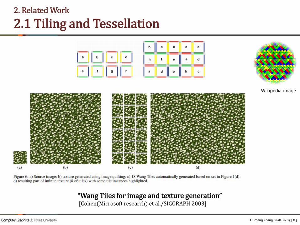
2. Related Work
2.1 Tiling and Tessellation
“Wang Tiles for image and texture generation”[Cohen(Microsoft research) et al./SIGGRAPH 2003]
Wikipedia image

Qi-meng Zhang| 2018. 10. 25 | # 6Computer Graphics @ Korea University
• Quasicrystal pattern
2. Related Work
2.2 Crystallography
“A Guide to the Symmetry Structure of Quasiperiodic Tiling Classes”[ J Hermisson(University of Vienna) et al./Journal de Physique 1997]
Inflation Rule: square-triangle tiling with12-fold symmetry

Qi-meng Zhang| 2018. 10. 25 | # 7Computer Graphics @ Korea University
2. Related Work
2.3 Surface Meshing
“Regular Meshes from Polygonal Patterns”[ Vaxman(Utrecht University) et al./TOG2017]
“Pattern-Based Quadrangulation for N-sides Patches”[ Takayama(ETH Zurich) et al./CGF2014]

Qi-meng Zhang| 2018. 10. 25 | # 8Computer Graphics @ Korea University
2. Related Work
2.4 Architecture
“Polyhedral Patterns”[ Jiang (KAUST) et al./TOG 2015]
Yas Mall(Abu Dhabi)Islamic Art Exhibition(Louvre) Fiera Milano
Qi-meng Zhang| 2018. 10. 25 | # 9Computer Graphics @ Korea University
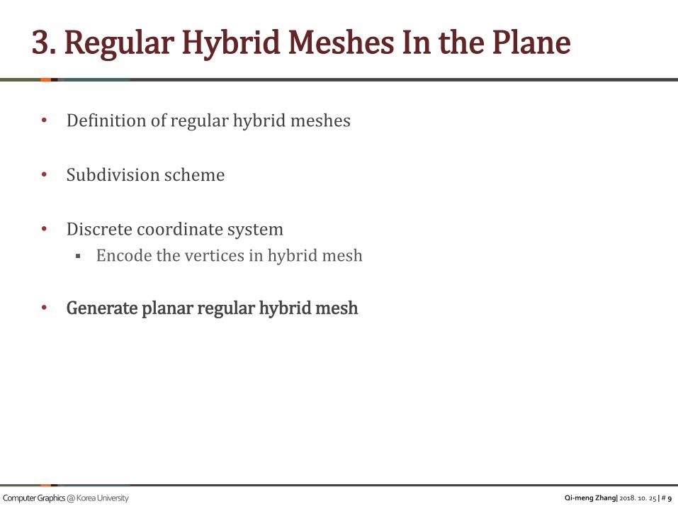
• Definition of regular hybrid meshes
• Subdivision scheme
• Discrete coordinate system
▪ Encode the vertices in hybrid mesh
• Generate planar regular hybrid mesh
3. Regular Hybrid Meshes In the Plane
Qi-meng Zhang| 2018. 10. 25 | # 10Computer Graphics @ Korea University
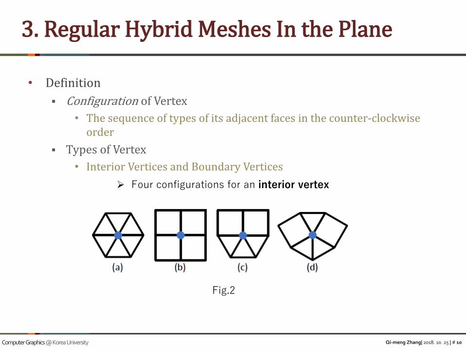
• Definition
▪ Configuration of Vertex
• The sequence of types of its adjacent faces in the counter-clockwise order
▪ Types of Vertex
• Interior Vertices and Boundary Vertices
3. Regular Hybrid Meshes In the Plane
Fig.2
➢ Four configurations for an interior vertex

Qi-meng Zhang| 2018. 10. 25 | # 11Computer Graphics @ Korea University
• Boundary vertices: can be distinguished by boundary angle▪ any integer multiple of
▪ 12 possible directions for half-edge(*)
• Each half-edge’s direction can encode as an integer
3. Regular Hybrid Meshes In the Plane
➢ All configurations for boundary angles
Fig.2
(*)We assume the half-edges of a face circulate in the counter-clockwise order
∈ [0,11]
Qi-meng Zhang| 2018. 10. 25 | # 12Computer Graphics @ Korea University
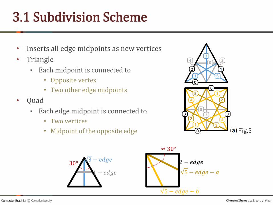
• Inserts all edge midpoints as new vertices
• Triangle
▪ Each midpoint is connected to
• Opposite vertex
• Two other edge midpoints
• Quad
▪ Each edge midpoint is connected to
• Two vertices
• Midpoint of the opposite edge
3.1 Subdivision Scheme
Fig.3
5 − 𝑒𝑑𝑔𝑒 − 𝑎
2 − 𝑒𝑑𝑔𝑒3 − 𝑒𝑑𝑔𝑒
1 − 𝑒𝑑𝑔𝑒
30°
≈ 30°
5 − 𝑒𝑑𝑔𝑒 − 𝑏

Qi-meng Zhang| 2018. 10. 25 | # 13Computer Graphics @ Korea University
• Main path
▪ A connected sequence of half-edges with the same direction label
3.1 Subdivision Scheme
12 directionsFig.3
➢ Main paths at the 12 directions form a vertex
0
1
234
5
6
7
89
1011
Qi-meng Zhang| 2018. 10. 25 | # 14Computer Graphics @ Korea University
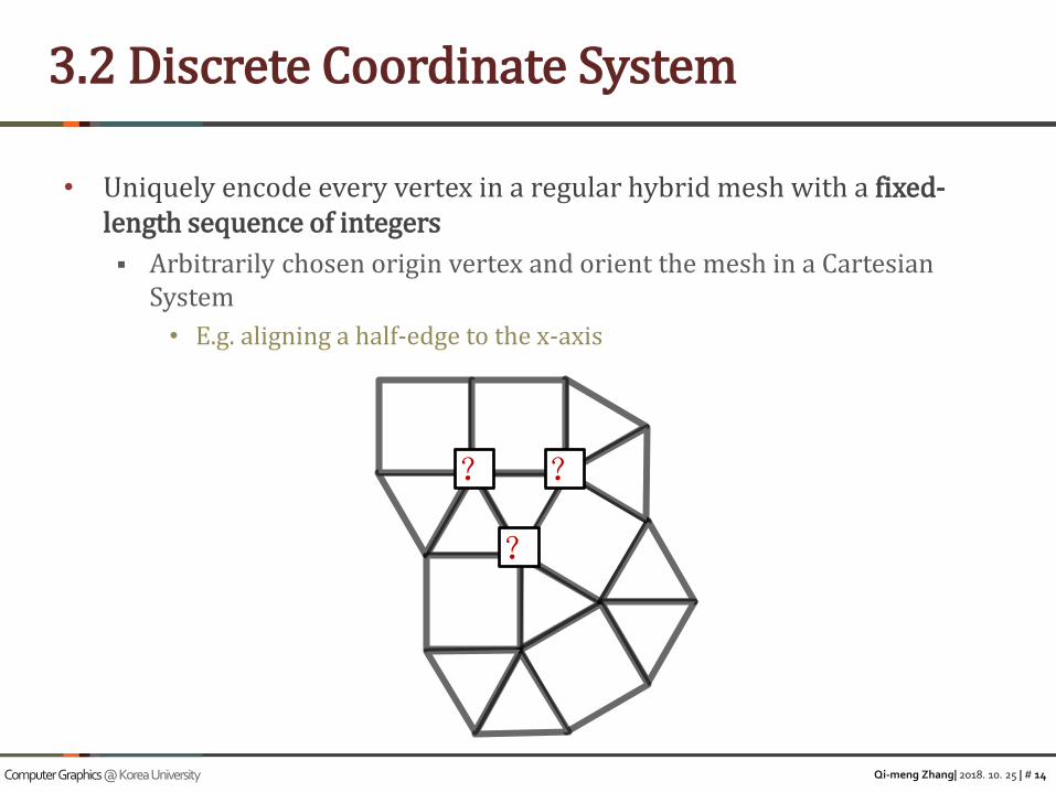
• Uniquely encode every vertex in a regular hybrid mesh with a fixed-length sequence of integers
▪ Arbitrarily chosen origin vertex and orient the mesh in a Cartesian System
• E.g. aligning a half-edge to the x-axis
3.2 Discrete Coordinate System
?
?
?
Qi-meng Zhang| 2018. 10. 25 | # 15Computer Graphics @ Korea University
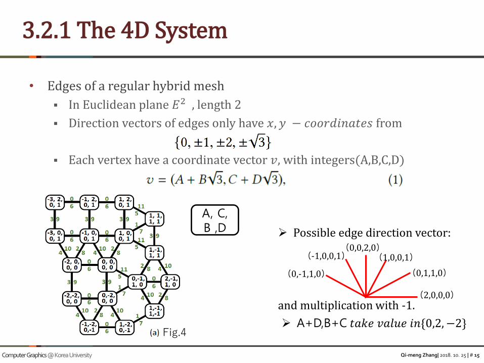
• Edges of a regular hybrid mesh
▪ In Euclidean plane 𝐸2 , length 2
▪ Direction vectors of edges only have 𝑥, 𝑦 − 𝑐𝑜𝑜𝑟𝑑𝑖𝑛𝑎𝑡𝑒𝑠 from
▪ Each vertex have a coordinate vector 𝑣, with integers(A,B,C,D)
3.2.1 The 4D System
Fig.4
➢ Possible edge direction vector:
and multiplication with -1.
A, C,B ,D
(2,0,0,0)
(1,0,0,1)
(0,1,1,0)
(0,0,2,0)(-1,0,0,1)
(0,-1,1,0)
➢ A+D,B+C 𝑡𝑎𝑘𝑒 𝑣𝑎𝑙𝑢𝑒 𝑖𝑛{0,2, −2}

Qi-meng Zhang| 2018. 10. 25 | # 16Computer Graphics @ Korea University
• (A,B,C,D)—>(x1,y1)
▪ Main path in : 0-,3-,6-,9-th direction
become straight
▪ Length 2 and length 3 are mapped to same
vector
• 4D-coordinates(2,0,0,0),(0,1,0,0)
▪ Linear map P1
▪ 5-edge can project into (±5,0)or(0, ±5)
3.2.2 Projection 1
0
1
234
5
6
7
89
1011
Fig.4
Qi-meng Zhang| 2018. 10. 25 | # 17Computer Graphics @ Korea University
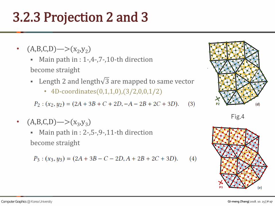
• (A,B,C,D)—>(x2,y2)
▪ Main path in : 1-,4-,7-,10-th direction
become straight
▪ Length 2 and length 3 are mapped to same vector
• 4D-coordinates(0,1,1,0),(3/2,0,0,1/2)
• (A,B,C,D)—>(x3,y3)
▪ Main path in : 2-,5-,9-,11-th direction
become straight
3.2.3 Projection 2 and 3
Fig.4
Qi-meng Zhang| 2018. 10. 25 | # 18Computer Graphics @ Korea University
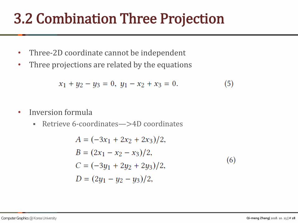
• Three-2D coordinate cannot be independent
• Three projections are related by the equations
• Inversion formula
▪ Retrieve 6-coordinates—>4D coordinates
3.2 Combination Three Projection
Qi-meng Zhang| 2018. 10. 25 | # 19Computer Graphics @ Korea University
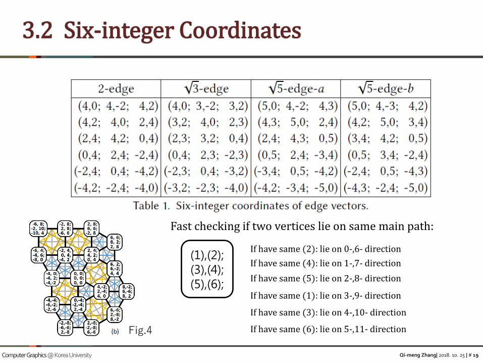
3.2 Six-integer Coordinates
Fig.4
Fast checking if two vertices lie on same main path:
(1),(2);(3),(4);(5),(6);
If have same (2): lie on 0-,6- direction
If have same (4): lie on 1-,7- direction
If have same (5): lie on 2-,8- direction
If have same (1): lie on 3-,9- direction
If have same (3): lie on 4-,10- direction
If have same (6): lie on 5-,11- direction
Qi-meng Zhang| 2018. 10. 25 | # 20Computer Graphics @ Korea University
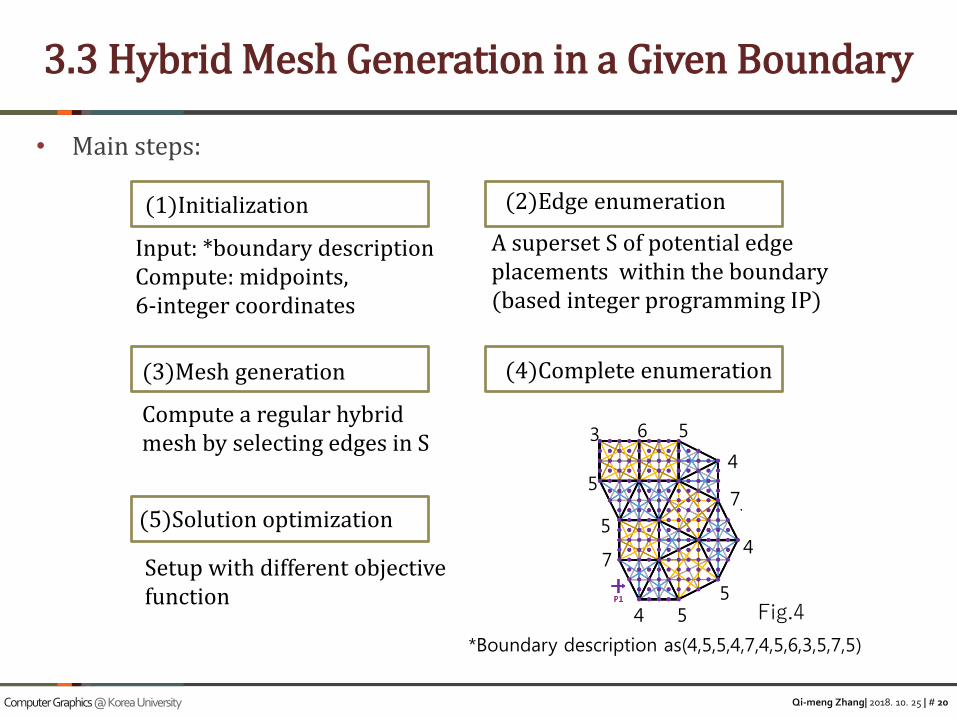
• Main steps:
3.3 Hybrid Mesh Generation in a Given Boundary
(1)Initialization (2)Edge enumeration
(3)Mesh generation (4)Complete enumeration
(5)Solution optimization
Input: *boundary descriptionCompute: midpoints,6-integer coordinates
A superset S of potential edgeplacements within the boundary(based integer programming IP)
Compute a regular hybrid mesh by selecting edges in S
Setup with different objective function
4 55
4
7
4
563
5
5
7
Fig.4
*Boundary description as(4,5,5,4,7,4,5,6,3,5,7,5)
Qi-meng Zhang| 2018. 10. 25 | # 21Computer Graphics @ Korea University
• Enumeration
▪ All pairs of boundary points (vertices and
midpoints)could lie on a main path inside the
boundary
▪ All possible edges between all pairs
• Test lie on a main path
▪ Coordinate test
▪ Inside test
▪ Decomposition test
• Decomposed into 1-edges, 3-edges, 5-edges-a/b
▪ IP problem
3.3.1 Edge Enumeration
Fig. 5.
Fig. 5.
Qi-meng Zhang| 2018. 10. 25 | # 22Computer Graphics @ Korea University
• Integer Programming
▪ Additional constraint that some or all Variables are restricted to be integers
• Decomposition test
▪ Solving following IP problem
• V denote the 6-integer vector between the two points
• (t0,t1,t2,t3) denote the numbers of the four edge types(1-edge, 3-
edges, 5-edges-a/b)
• Ti is the six-integer vector encoding edge type i in a direction
• (x0,x1,x2,x3) denote all possible edge combinations
3.3.1 Edge Enumeration

Qi-meng Zhang| 2018. 10. 25 | # 23Computer Graphics @ Korea University
• Enumerate unique potential placements of vertices
▪ Based on 4D coordinates
• Enumerate all possible edge configuration about vertices.
3.3.2 Mesh Generation
j
➢ 𝐸𝑖 and 𝐶𝑗, 𝑚 are Boolean various
➢ Nj is the number of edge placements adjacent to vj
The configuration active if and only if all corresponding edge are selectedand all other edges at vj are not selected

Qi-meng Zhang| 2018. 10. 25 | # 24Computer Graphics @ Korea University
• Complete IP problem formulate as
3.3.2 Mesh Generation
Constraint 4
Constraint 3
Constraint 2
Boolean various
• Complete Enumeration
Qi-meng Zhang| 2018. 10. 25 | # 25Computer Graphics @ Korea University
• Adding objective function to IP problem
3.3.4 Configuration Optimization
Fig.6 Fig.7
Penalizing:40 “butterfly”
Prioritizing:84“butterfly”
“butterfly” configuration
Penalizing:as-regular-as-possible
Penalizing:as-fractured-as-possible
Weight for Cj,m
Qi-meng Zhang| 2018. 10. 25 | # 26Computer Graphics @ Korea University
• Adding following function to objective function
3.3.5 Symmetry Optimization
Fig.6
Fig.7
Scalar field
Qi-meng Zhang| 2018. 10. 25 | # 27Computer Graphics @ Korea University
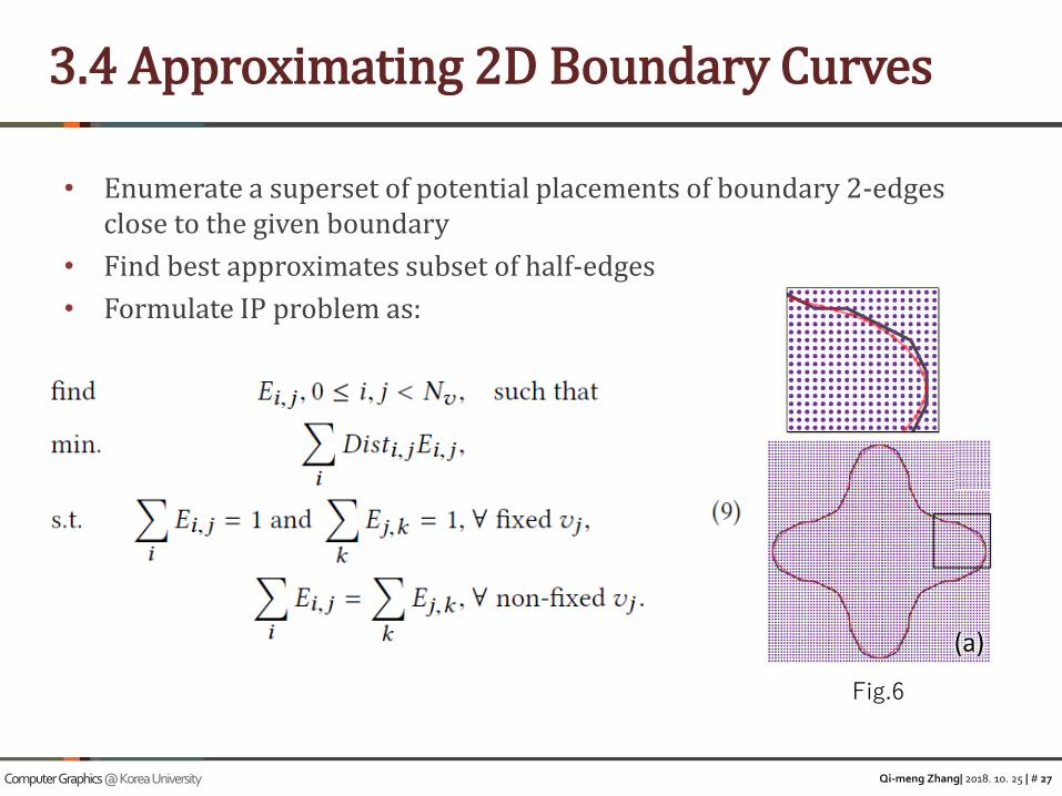
• Enumerate a superset of potential placements of boundary 2-edges close to the given boundary
• Find best approximates subset of half-edges
• Formulate IP problem as:
3.4 Approximating 2D Boundary Curves
Fig.6
Qi-meng Zhang| 2018. 10. 25 | # 28Computer Graphics @ Korea University
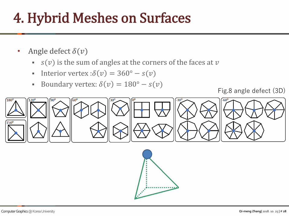
• Angle defect 𝛿(𝑣)
▪ 𝑠(𝑣) is the sum of angles at the corners of the faces at 𝑣
▪ Interior vertex :𝛿 𝑣 = 360° − 𝑠(𝑣)
▪ Boundary vertex: 𝛿 𝑣 = 180° − 𝑠(𝑣)
4. Hybrid Meshes on Surfaces
Fig.8 angle defect (3D)

Qi-meng Zhang| 2018. 10. 25 | # 29Computer Graphics @ Korea University
• In 3D
▪ Angle defect= discrete Gaussian curvature(if angles are measured in radians)
• Nearly regular 3D hybrid meshes (hybrid mesh)
▪ Combinatorial angles(c-angle)
• At the vertices of a triangle or quad to be 60° or 90°
▪ Combinatorial edge lengths (c-length)
4 Hybrid Meshes on Surfaces
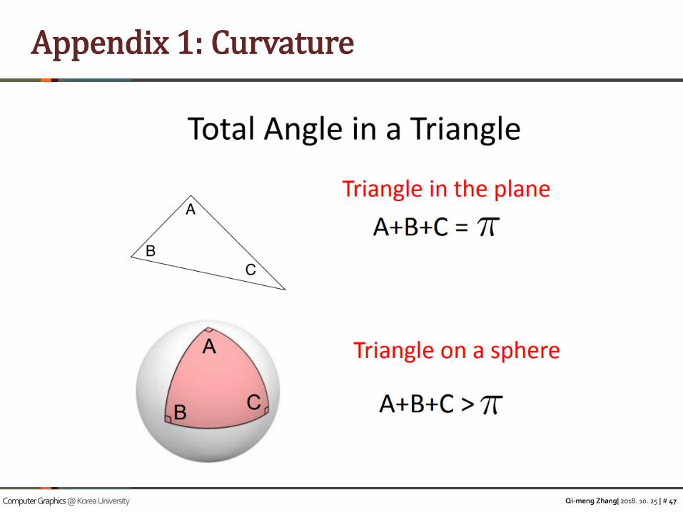
*Appendix 1
Qi-meng Zhang| 2018. 10. 25 | # 30Computer Graphics @ Korea University
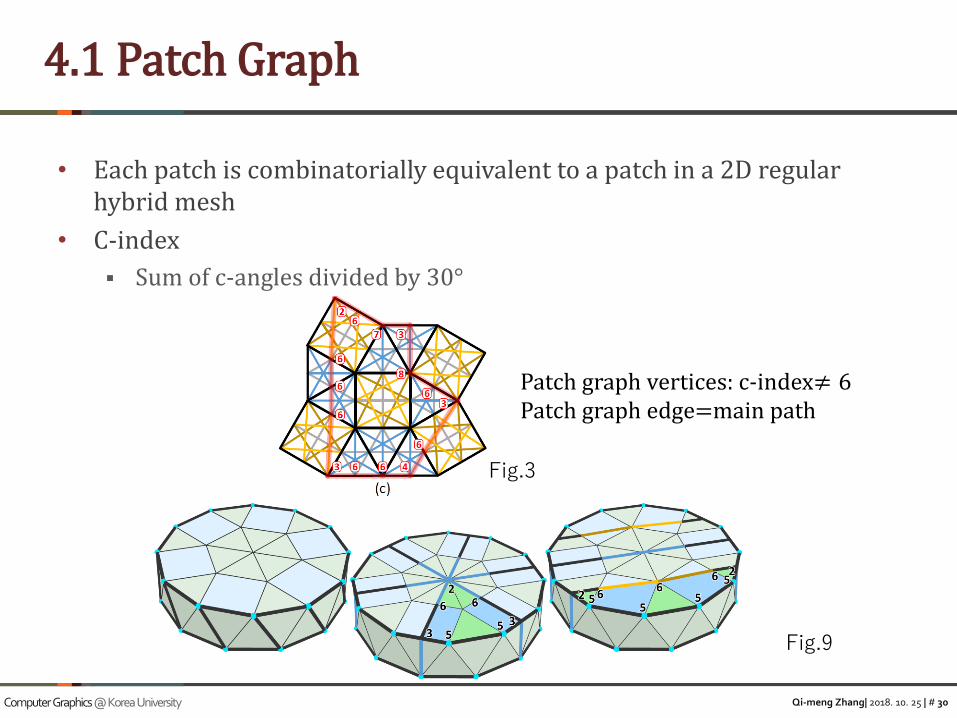
• Each patch is combinatorially equivalent to a patch in a 2D regular hybrid mesh
• C-index
▪ Sum of c-angles divided by 30°
4.1 Patch Graph
Patch graph vertices: c-index≠ 6Patch graph edge=main path
Fig.9
Fig.3

Qi-meng Zhang| 2018. 10. 25 | # 31Computer Graphics @ Korea University
• Overview
4.2 Generating Hybrid Meshes on Surfaces
Fig.10
Qi-meng Zhang| 2018. 10. 25 | # 32Computer Graphics @ Korea University
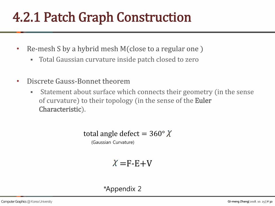
• Re-mesh S by a hybrid mesh M(close to a regular one )
▪ Total Gaussian curvature inside patch closed to zero
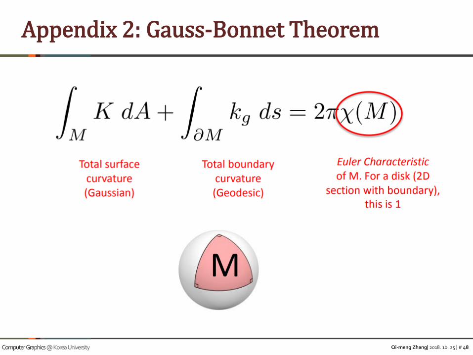
• Discrete Gauss-Bonnet theorem
▪ Statement about surface which connects their geometry (in the sense of curvature) to their topology (in the sense of the Euler Characteristic).
4.2.1 Patch Graph Construction
total angle defect = 360°
=F-E+V
(Gaussian Curvature)
*Appendix 2
Qi-meng Zhang| 2018. 10. 25 | # 33Computer Graphics @ Korea University
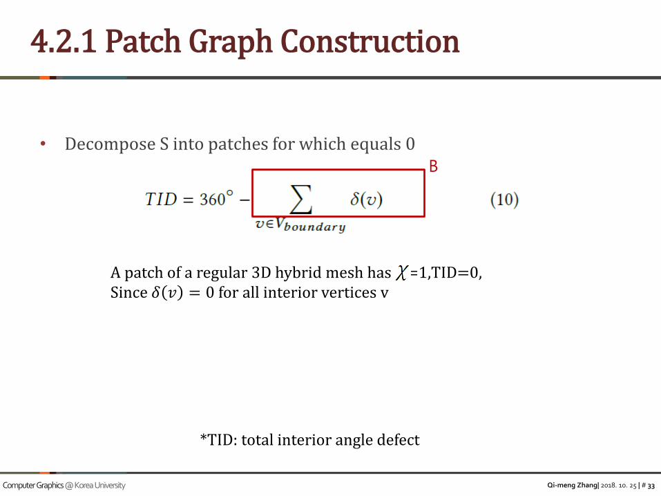
• Decompose S into patches for which equals 0
4.2.1 Patch Graph Construction
A patch of a regular 3D hybrid mesh has =1,TID=0,Since 𝛿 𝑣 = 0 for all interior vertices v
B
*TID: total interior angle defect

Qi-meng Zhang| 2018. 10. 25 | # 34Computer Graphics @ Korea University
• Compute TID for a disk-like region
▪ 1) Compute B(boundary angle defect)
• Using 3D surface geometric angle
▪ 2) Calculate c-indices
• Round angle to closest integer multiple of 30
▪ 3) Find boundary points
▪ 4) Assign c-indices Ij to corners vj
• As close as to their inner angle
4.2.1 Patch graph construction
TID=
➢ Compute angles by LSCM (least squares conformal maps)➢ Mesh ->UV parametrization➢ Reference Library: Libigl

Qi-meng Zhang| 2018. 10. 25 | # 35Computer Graphics @ Korea University
• Subdivision process
4.2.1 Patch Graph Construction

Qi-meng Zhang| 2018. 10. 25 | # 36Computer Graphics @ Korea University
4.2.1 Patch graph construction
• Score of partitions

Qi-meng Zhang| 2018. 10. 25 | # 37Computer Graphics @ Korea University
• To obtain a patch graph
4.2.1Turning the Final Partition into a Patch Graph
➢ Li :actual lengths of graph edges in 3D
➢ Ea:the 6-integer vector of the 2-edge in the a-th direction
➢ Ia,fj:indicates the lists of indices of 2-edges circulating fj in the a-th direction
Qi-meng Zhang| 2018. 10. 25 | # 38Computer Graphics @ Korea University
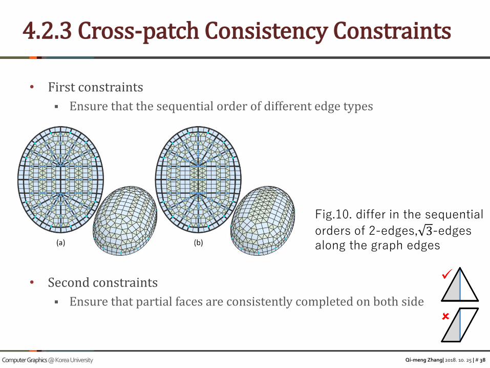
• First constraints
▪ Ensure that the sequential order of different edge types
• Second constraints
▪ Ensure that partial faces are consistently completed on both side
4.2.3 Cross-patch Consistency Constraints
Fig.10. differ in the sequential
orders of 2-edges, 3-edgesalong the graph edges

Qi-meng Zhang| 2018. 10. 25 | # 39Computer Graphics @ Korea University
• Rotational symmetry optimization
▪ Euclidean Regularity
• A perfectly Euclidean-regular mesh are regular polygons, all edges must have the same length
• Global regularity optimization
• Planarity quads optimization
▪ Minimizing the difference between discrete curvatures of original and optimized mesh
4.2.4 Post-processing
“Regular Meshes from Polygonal Patterns”[ Vaxman(Utrecht University) et al./TOG2017]

Qi-meng Zhang| 2018. 10. 25 | # 40Computer Graphics @ Korea University
• Altering the c-indices of an existing patch graph
• E.x. zigzags
4.3 Patch Graph Editing

Qi-meng Zhang| 2018. 10. 25 | # 41Computer Graphics @ Korea University
5. Results and applications
5.1 3D Hybrid Mesh Design
Fig. 14.
Fig. 15.
ER-results

Qi-meng Zhang| 2018. 10. 25 | # 42Computer Graphics @ Korea University
5.1 3D Hybrid Mesh Design
Fig. 17.

Qi-meng Zhang| 2018. 10. 25 | # 43Computer Graphics @ Korea University
5.2 Architectural Geometry
Fig. 18.
planarity optimization score
fractured patterns

Qi-meng Zhang| 2018. 10. 25 | # 44Computer Graphics @ Korea University
5.2 Architectural Geometry
Fig. 19.
Fig. 22.

Qi-meng Zhang| 2018. 10. 25 | # 45Computer Graphics @ Korea University
• Limitation
▪ Do not have a theoretical study of necessary and sufficient conditions that a given 2D boundary admits at least one regular hybrid mesh solution.
▪ Considerable effort is needed to ensure the feasibility of 2D solutions when manually designing patch graphs.
• Future work
▪ Volumetric extensions
6. Limitation and Future work
Fig.23

Qi-meng Zhang| 2018. 10. 25 | # 46Computer Graphics @ Korea University
Result Video
Qi-meng Zhang| 2018. 10. 25 | # 47Computer Graphics @ Korea University
Appendix 1: Curvature
Qi-meng Zhang| 2018. 10. 25 | # 48Computer Graphics @ Korea University
Appendix 2: Gauss-Bonnet Theorem

Qi-meng Zhang| 2018. 10. 25 | # 49Computer Graphics @ Korea University
Appendix 2: Gauss-Bonnet Theorem

Qi-meng Zhang| 2018. 10. 25 | # 50Computer Graphics @ Korea University
Appendix 2: Gauss-Bonnet Theorem