
Designers guiDe - Vandernet · Designers guiDe Always read and ... It is important that this guide...
26
DESIGNERS GUIDE Always read and follow the warnings and instructions for use © Copyright Capital Safety Systems Ltd 2013 RoofSafe ™ Anchors THE ULTIMATE IN FALL PROTECTION
Transcript of Designers guiDe - Vandernet · Designers guiDe Always read and ... It is important that this guide...

Designers guiDe
Always read and follow the warnings and instructions for use© Copyright Capital Safety Systems Ltd 2013
RoofSafe™ Anchors
T H E U L T I M A T E I N F A L L P R O T E C T I O N

RoofSafe™ AnchorContents
2Issue Date: 10/05/13 Issue No: 2
1.0 FoRewoRd
2.0 GeneRAl
2.1 Authorised Installers
2.2 Conformity
2.3 Work Restraint & Fall Arrest
2.4 Free Fall Space Calculator
3.0 Site ASSeSSment
3.1 Reviewing the Task
3.2 Typical System Layout
3.3 Specifying Your Anchor
3.4 Roof Types & Anchors
3.4.1 Wood Deck (Built up)
3.4.2 Metal Deck (Built up / Composite)
3.4.3 Solid Concrete (Built up)
3.4.4 Hollow Concrete (Built up)
3.4.5 Trapezoidal Insulated Panel
3.4.6 Standing Seam
3.5 Sealing Details
3.6 Aggressive & Hazardous Environments
3.7 Rescue Planning
4.0 RooFSAFe™ AnchoR PeRFoRmAnce
4.1 Anchorage Strength
4.2 Forces on the SpiraTech™ Anchor
4.3 Forces on a Tip Over Anchor
4.4 Thermal Bridging
5.0 AnnuAl mAintenAnce
5.1 Testing the Roof Anchor
5.2 Testing the Swages
5.3 Cleaning the Anchor
6.0 ReFeRence documentS
6.1 Abbreviations and Definitions
6.2 Standards Table
6.3 Markings Explained
6.4 Inspection log.

1.0 FoRewoRd
It is important that this guide is read and fully understood before the RoofSafe™ Anchors or RoofSafe™ Cable system is installed or serviced. The RoofSafe™ Anchor has been designed to prevent or minimise the risk of injury from falls. Incorrect design, installation or servicing through failure to adhere to these instructions could result in serious consequences.
This guide outlines applications for each anchor and each typical roof type that the designer may encounter including recommended fixing types and methods. It explains the forces on the anchor and the system and how this relates to the forces transferred to the roof structure.
Information on the anchors performance, details of standards to which the anchors conform and testing which has been carried out by Capital Safety are given for reference to ensure that the correct product is being used for each specific application.
It is important that management ensure that personnel who they direct to install or service the RoofSafe™ Anchor products are trained to the standards expected by Capital Safety.
This guide is an essential reference document for designing a RoofSafe™ Anchor and RoofSafe™ Cable System.
RoofSafe™ Anchor1.0 Foreword
3Issue Date: 10/05/13 Issue No: 2
2.0 GeneRAl
2.1 AuthoRiSed inStAlleRS
Only competent installers certified by Capital Safety are allowed to install and service the RoofSafe™ Anchor or RoofSafe™ Cable System.
2.2 conFoRmity
The RoofSafe™ Anchor System is a roof top anchorage system which is tested and where appropriate certified in accordance with the requirements of various national and international standards and codes of practice. Details can be found in standards table, Section 6.2.
Components or parts are not to be altered, modified, dismantled or be replaced with items not supplied or manufactured by Capital Safety, such action will invalidate any certification and could result in serious or fatal consequences.
Parts or components not supplied by Capital Safety may be of inferior specification and may cause incorrect operation of the system.
2.3 woRk ReStRAint & FAll ARReSt
The RoofSafe™ Anchor is a complete fall protection system. It has been designed to solve problems relating to falls from a height. All Anchors for all structure’s must be designed for fall arrest, although it is best to restrain the user to prevent a fall occurring.
WOrK resTrAinT
The advantages with work-restraint are that:
• Workers do not have to be subjected to the abrupt impact of an arrest as would be the case in a fall-arrest system, or risk falling into a hazard e.g. water or a hazardous substance.
• The user can not be injured from swing-fall incidents.
• There is no need for any rescue provision.
• Personnel require less training.
RoofSafe™ Anchor2.0 General
4Issue Date: 10/05/13 Issue No: 2

A
B
AB
Fall Arrest OrientationWork restraint Orientation
In a work restraint system, to prevent the worker from entering an area where they could fall, there are two dimensions which need to be strictly controlled:
• The lanyard length A (Fig 1)
• The distance from the Anchor to the fall hazard B (Fig 1)
A scale drawing should be made to ensure that the lanyard (including connectors) will always prevent the user from entering a fall arrest situation. If the position of the fall hazard relative to the Anchor varies this analysis should be performed at various points along the length of the system.
FALL ArresT
Where a work restraint system cannot be employed, a fall-arrest system has to be used. The disadvantage is that a worker has to fall before the system can operate (Fig 2) and arrest the fall. This is achieved by applying a braking force to the worker for a few hundredths of a second. The RoofSafe™ Anchor and RoofSafe™ Cable systems ensure that the braking force is always kept below a safe load, providing that the worker is wearing a full body harness and an energy-absorbing lanyard certified to the appropriate national standard.
When designing the roof safety system, be aware of falls through fragile elemnts as well as falls from exposed edges.
In a fall arrest situation appropriate rescue procedures must be in place to return the worker to safety as soon as possible. Refer to the Rescue planning section of this guide (Section 3.7).
iMPOrTAnT nOTe
Whilst all horizontal lifeline systems must be designed for Fall Arrest in case of accidental misuse, it is recommended that system should be designed for Work Restraint. This design enables a user to access their work area whilst being prevented from being exposed to a fall hazard. This design will reduce risk and mitigate the consequences of a fall.
RoofSafe™ Anchor2.0 General
5Issue Date: 10/05/13 Issue No: 2
FiG 1 FiG 2

InputsTitle Character Units Values Description
Lanyard Length L m Total length of lanyard
Edge Distance E m Distance from the edge of the roof to the system
Number of Users U # Total number of users per span
D-Ring Height D m Height from roof surface to the user connection point
System Length S m Total length of system (or section of system)
OutputsTitle Character Units Value
Fall potential FP m
Fall factor (fall potential / lanyard length) FF m
Minimum distance required below platform level MD m
Maximum end loads ML kN
Free Fall Space Calculator
Issue No: 01 Issue Date: 05/03/2012
Using the input boxes below, change the values to suit the length of your RoofSafe Cable & Anchor system. Note: Calculations are based on maximum span widths (12m) with the fall occuring in the midspan of the system.
Project Name Date
RoofSafe™ AnchorsRoofSafe™ Cable
2.4 FRee FAll SPAce cAlculAtoR
Capital Safety provides a calculation tool which helps the designer to assess the recommended free space required below the system to ensure that the system is safe to use. The calculation tool and information on how to use it is available from Capital Safety separately from this guide.
Below is a picture of the calculation sheet (Fig 3)
RoofSafe™ Anchor2.0 General
6Issue Date: 10/05/13 Issue No: 2
FiG 3

3.0 Site ASSeSSment
3.1 ReviewinG the tASk
Only installers certified by Capital Safety are allowed to install and service the RoofSafe™ Anchors and RoofSafe™ Anchor Cable Systems.
siTe surVeY
At the start of each job a site survey should be carried out to assess the type and location of the system required. Accurate measurements should be taken to make sure that the system will fit the required area correctly.
During a site survey the following information should be gathered:
• The purpose of the system / Task to be performed
• The maximum No. of people that will be using the system at any one time.
• The specification and manufacturer of the roof to which the system will be fitted, including critical dimensions such as seam/crown centres and insulation thickness
• Scale drawings of the structure or building (in digital format if available)
• The exact path of the system
• Any special requirements from the architect or the customer such as; a specific type of bracket, or particular considerations for historical buildings.
• The risks to the installers so that suitable risk controls during installation can be planned.
When seeking technical support on a specific job, the Capital Safety sales team will be able to help you more quickly if you have the above information available as a minimum.
MeTHOD sTATeMenTs
Before work begins a method statement should be written by the installer, agreed with the client and signed by both the parties. This is a detailed step by step guide of how the work is to be carried out by the installer.
The method statement protects both the client and the installer in the event of the work not being carried out in a safe manner, and can be used to ensure that the workers are adhering to safe and suitable working practices while carrying out the work.
VeriFYing THe rOOF sTruCTure
The strength of the roof structure should be verified before the system is fitted to ensure that the fixings are strong enough to hold the anchor onto the roof. This can be done by calculation or through roofing approvals. Contact Capital Safety for any specific roof testing that may be relevant to the roof profile
Where these methods can not be used to verify the strength of the structure and the fixings, a sample fixing should be installed, and pull tested. The fixings should withstand as a minimum the forces given in the RoofSafe™ Anchor Forces Calculation Sheet.
RoofSafe™ Anchor3.0 Site Assessment
7Issue Date: 10/05/13 Issue No: 2

KeY:
A - SpiraTech™ Anchor as System end post
B - SpiraTech™ Anchor as Corner post
C - Tip Over Anchor as Intermediate post
D - SpiraTech™ Anchor as System t-joint, with RA throw plate
E - SpiraTech™ Anchor as Variable post for roof hips
B E E B
D
E
EA
A
C
A
Direction of Fall Hazard
Max
12m
3.2 tyPicAl SyStem lAyout
RoofSafe™ Anchor3.0 Site Assessment
8Issue Date: 10/05/13 Issue No: 2

A
A
B
C
D
E
B
A
BC
D
F
E
Fig 9.1 shows the potential swing fall and the inaccessible areas. Fig 9.2 shows how the swing fall potential can be limited when using a manually adjustable lanyard and an single point anchor as an anti swing fall post. Further information can be found in BS7883:2005.
A) Inaccessible zone
B) Zone for potential swing fall
C) User
D) Lanyard
E) RoofSafe™ Anchor System
A) Swing fall zone
B) Accessible area with anti swing fall posts
C) User
D) Lanyard
E) RoofSafe™ Anchor System
F) Single point anchor as anti swing fall post
Ridge Height
Frank Length
gAining ACCess TO THe AnCHOr
The entry point is defined as the point where the user can attach to the system. The exit point is defined as the point where the user can detach from the system. The entry point and the exit point can be at the same position. It is important to remember that the user is not fully protected from a fall until the safety lanyard and harness are attached and secured to the attachment eye or Unigrab, via a carabiner. Consideration should always be given to the positioning of the Anchor in regards to the above. The entry point should always be in a safe area, i.e. free from fall hazards. Where this cannot be achieved, a secondary means of fall protection needs to be installed to give protection whilst bridging the gap between the access route and the Anchor. The same consideration needs to be made in respect to the exit point, should it be in a different position to the entry point.
sWing FALLs
Swing falls can be fatal when working near a gable end. Fig 8 shows a worker using a rope and grab at maximum extension near a gable end. In this case the flank length exceeds the ridge height so if the user falls they have inadequate clearance to ground level. Another risk is the slicing effect of the edge of the roof on the rope or lanyard as the user falls. This situation must be avoided. Installation of edge protection to the end elevation and Installing the Anchor inboard of the roof eaves can help to alleviate this issue.
RoofSafe™ Anchor3.0 Site Assessment
9Issue Date: 10/05/13 Issue No: 2
FiG 8
FiG 9.1 FiG 9.2

++
Can be used as a single point anchor for up to two users
Can be used as a single point anchor for one user.
3.3 SPeciFyinG youR AnchoR
The RoofSafe™ Anchor provides a secure anchor point for a worker at height, close to an exposed edge or other fall hazards, when used in conjunction with associated PPE, such as a full body harness and a energy absorbing lanyard.
The RoofSafe™ Anchor is designed to re-orientate and deploy an energy absorber in the event of a fall, thereby reducing the load transferred to the user and the roofing system. The Anchor can be used for both fall arrest and work restraint applications.
There are two types of Anchors within the range. The SpiraTech™ Anchor and the Tip Over Anchor. Both anchors are modular in design allowing for speed of fitting and use.
Both Anchors allow the user to walk 360 degrees around the anchor without needing to reorientate the lanyard or connectors. The Anchor allows full weather sealing to prevent water ingress, and allows different roof membranes to be fitted and sealed around the anchor for true weather proofing.
The modular design allows the designer to chose and purchase the baseplate, module and top attachment separately. This gives true flexibility for application to any roof type or membrane.
FiG 10.1 BASe PlAte
FiG 11.1 ASSemBled SPiRAtech™ AnchoR
FiG 10.2 SPiRAtech™ oR tiP oveR module
FiG 11.2 ASSemBled tiP oveR AnchoR
FiG 10.3 AttAchment eye
RoofSafe™ Anchor3.0 Site Assessment
10Issue Date: 10/05/13 Issue No: 2
Roof TypePitches (mm)
Trapezoidal Standing Seam
Base Plates 200 250 275 300 304 333 334 347 350 367 400 500 200 300 400
RA Base Plate 405x405 Holes7241136
x x x x x x x x
RA Base Plate 405x405 Blank7241137
x x x x x x x x x x x x
RA Base Plate 350x440 Holes7241138
x x x x
RA Base Plate 350x440 Blank7241139
x x x x x x x x x x x x x x
RA Base Plate 550x450 Blank7241140
x x x x x x x x x x x x x x x
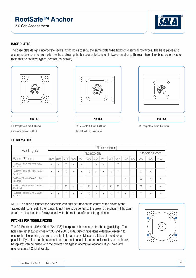
PiTCH MATriX
NOTE: This table assumes the baseplate can only be fitted on the centre of the crown of the trapezoidal roof sheet, if the fixings do not have to be central to the crowns the plates will fit sizes other than those stated. Always check with the roof manufacturer for guidance
RA Baseplate 405mm X 405mm
Available with holes or blank
RA Baseplate 350mm X 440mm
Available with holes or blank
RA Baseplate 550mm X 450mm
BAse PLATes
The base plate designs incorporate several fixing holes to allow the same plate to be fitted on dissimilar roof types. The base plates also accommodate common roof pitch centres, allowing the baseplates to be used in two orientations. There are two blank base plate sizes for roofs that do not have typical centres (not shown).
PiTCHes FOr TOggLe FiXing
The RA Baseplate 405x405 H (7241136) incorporates hole centres for the toggle fixings. The holes are set at two pitches of 333 and 200. Capital Safety have done extensive research to ensure that these fixing centres are suitable for as many styles and pitches of roof deck as possible. If you find that the standard holes are not suitable for a particular roof type, the blank baseplates can be drilled with the correct hole type in alternative locations. If you have any queries contact Capital Safety.
FiG 12.1 FiG 12.2 FiG 12.3
RoofSafe™ Anchor3.0 Site Assessment
11Issue Date: 10/05/13 Issue No: 2

3.4 RooF tyPeS And AnchoRS
Images of anchors in this section are for indicative purposes only
FiG 13.1
FiG 13.3
FiG 13.2
RoofSafe™ Anchor3.0 Site Assessment
12Issue Date: 10/05/13 Issue No: 2
3.4.1 WOOD DeCK, (BuiLT uP)
Built up roof type with rigid insulation and wooden roof deck. The deck must be a minimum thickness of 18mm
Fixings:
RoofSafe™ Anchor Toggle Fix 150mm x 4 (7241182)
RoofSafe™ Anchor Toggle Fix 300mm x 4 (7241183)
3.4.3 sOLiD COnCreTe, (BuiLT uP)
Warm solid concrete roof with rigid insulation.
Fixings:
RoofSafe™ Anchor Concrete Fix 150mm x 4 (7241180)
RoofSafe™ Anchor Concrete Fix 300mm x 4 (7241181)
3.4.2 MeTAL DeCK, (BuiLT uP / COMPOsiTe)
Built up or composite panel roof with rigid insulation and a Trapezoidal metal deck.
Fixings:
RoofSafe™ Anchor Toggle Fix 150mm x 4 (7241182)
RoofSafe™ Anchor Toggle Fix 300mm x 4 (7241183)

RoofSafe™ Anchor3.0 Site Assessment
13Issue Date: 10/05/13 Issue No: 2
FiG 13.4
FiG 13.6
FiG 13.5
3.4.4 HOLLOW COnCreTe, (BuiLT uP)
Warm hollow concrete roof with rigid insulation.
Fixings:
RoofSafe™ Anchor Concrete Fix 150mm x 4 (7241180)
RoofSafe™ Anchor Concrete Fix 300mm x 4 (7241181)
3.4.6 sTAnDing seAM
Standing seam roof, Aluminium Steel or Stainless Steel. Posts can be fitted to a range of seam profiles and roof sheet materials, see details on page 14.
3.4.5 TrAPeZOiDAL insuLATeD PAneL
Pre-insulated/
Built up metal roof panels.
Fixings:
RoofSafe™ 7.7 Rivet (7234005)

sTAnDing seAM rOOFing sYsTeMs
When Specifying a RoofSafe™ Anchor for a standing seam consideration should first be given to the Standing Seam profile and the type of clamps that will be required to secure the anchors to the roof
Capital Safety provides a range of fixing clamps to fit to varying roof seam profiles. Details on individual clamp compatibility can be provided by Technical Services.
The baseplate selection will be based on the roofing centres, see the matrix on page 11 for more detail.
iMPOrTAnT nOTe:
It is recommended to avoid fitting clamps directly over halter clips as this will affect the performance of the clamp and the roof. Always refer to the roofing manufacturer for guidance.
Bulb Type Standing Seam
RoofSafe™ Maxi Clamp E (7234008)
FiG 14
RoofSafe™ Maxi Clamp Z (7234028)
Folded Seam
Folded Seam
RoofSafe™ Maxi Clamp U (7234029)
RoofSafe™ Anchor3.0 Site Assessment
14Issue Date: 10/05/13 Issue No: 2

3.5 SeAlinG detAilS
RA Module PVC SpiraTech™ / Tip Over
RA Module All Mem SpiraTech™ / Tip Over
RA Module BIT SpiraTech™ / Tip Over
RA Module Top Fix SpiraTech™ / Tip Over
RoofSafe™ Anchor3.0 Site Assessment
15Issue Date: 10/05/13 Issue No: 2
Information in this section is given as a guide only, always refer to the roofing manufacturers information for their specifications.
PVC MeMBrAneA PVC bonded onto the weather
shround up to the ridgeB RA weather shroud PVCC BaseplateD Toggle fixing sealed in under the membrane
OTHer MeMBrAnesA Membrane sealed over the baseplate
and up to the top of the canB RA Weather CapC BaseplateD Toggle fixing sealed in under the membraneE RA Seal Ring
BiTuMen MeMBrAneA Bitumen sealed onto the weather
shround up to the ridgeB RA weather shroudC BaseplateD Toggle fixing sealed in under the bitumen
riVeT FiX AnD sTAnDing seAMA RA Seal RingB RA CanC BaseplateD Fixings with Seals or Clamps which
do not penetrate the roof.
AB
DC
AB
DC
D
BC
A
A
CED
B

3.6 AGGReSSive And hAzARdouS enviRonmentS
COrrOsiVe enVirOnMenTsThe RoofSafe™ Anchor has been tested in saline environments that exceed those specified in all National Standards. All components that are continuously exposed to the atmospheric conditions are made from Aluminium or Stainless Steel.
Aluminium components are anodized to AA11 (11 microns thick) as a minimum and 316 stainless steel components are polished to remove any surface impurities.
The SpiraTech™ coil and associated steel components are coated in a Zinc inorganic coating which has a minimum saline performance of 1000 Hrs.
In an aggressive or saline environment a RoofSafe™ Anchor and RoofSafe™ Cable System will require more frequent inspections and servicing to assure corrosion damage is not affecting the performance of the product. A appropriate inspection plan should be implemented based on the environmental conditions and agreed with the customer.
CHeMiCAL HAZArDsSolutions containing acids, alkali, or other caustic chemicals, especially at elevated temperatures may cause damage to this equipment. Consult Capital Safety if doubts exists concerning installing this equipment where chemical hazards are present.
eLeCTriCAL HAZArDsDo not install the RoofSafe™ Anchor where either the anchor, cable or user can come into contact with electrical power lines. Always allow a safe working distance between the user and power lines.
If you are uncertain about a particular application please contact your local energy infrastructure provider or health and safety advisory service for information on safe working practices.
3.7 ReScue PlAnninG
Employers have a reponsibility to make specific provisions for emergency planning. Work should be appropriately planned and previsions should be made for emergency situations. The need for rapid and appropriate response following a fall should not be ignored.
In any situation where a fall could occur it is essential that appropriate rescue equipment is available for rapid deployment by trained personnel. Failure to have correctly trained personnel and equipment in place to respond to a fall scenario may result in serious injury or death.
Capital Safety has a range of rescue equipment appropriate for different scenarios and can advise on specification and use. Capital Safety also has facilities to provide training which is essential for the safe and correct use of rescue and evacuation equipment.
RoofSafe™ Anchor3.0 Site Assessment
16Issue Date: 10/05/13 Issue No: 2
RoofSafe™ Anchor4.0 Roof Anchor Performance
17Issue Date: 10/05/13 Issue No: 2
4.0 RooF AnchoR PeRFoRmAnce
4.1 AnchoRAGe StRenGth
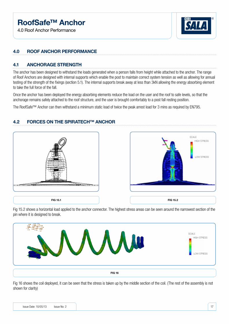
The anchor has been designed to withstand the loads generated when a person falls from height while attached to the anchor. The range of Roof Anchors are designed with internal supports which enable the post to maintain correct system tension as well as allowing for annual testing of the strength of the fixings (section 5.1). The internal supports break away at less than 3kN allowing the energy absorbing element to take the full force of the fall.
Once the anchor has been deployed the energy absorbing elements reduce the load on the user and the roof to safe levels, so that the anchorage remains safely attached to the roof structure, and the user is brought comfortably to a post fall resting position.
The RoofSafe™ Anchor can then withstand a minimum static load of twice the peak arrest load for 3 mins as required by EN795.
4.2 FoRceS on the SPiRAtech™ AnchoR
Fig 15.2 shows a horizontal load applied to the anchor connector. The highest stress areas can be seen around the narrowest section of the pin where it is designed to break.
Fig 16 shows the coil deployed, it can be seen that the stress is taken up by the middle section of the coil. (The rest of the assembly is not shown for clarity)
FiG 16
FiG 15.2FiG 15.1
SCALE
HIGH STRESS
LOW STRESS
SCALE
HIGH STRESS
LOW STRESS

Time (secs)
Forc
e (k
N)
Drop On Deployed SystemSystem
Time (secs)
Forc
e (k
N)
The SpiraTech™ Force management technology, absorbs much of the impact energy returning a low peak load as shown in the traces below Fig 17a/17b.
In a system the load is transmitted to the ends and the corners. Therefore ends and corners should be secured by means of a SpiraTech™ anchor rather than a Tip Over anchor. Tip Over anchors can be used as intermediate posts as they see less load. A system consisting of 2 SpiraTech™ anchors (Fig 18) will return a peak load of approximately 4.6kN (Fig 19).
However if a second user was to fall on the system after the anchor had already been deployed the peak load would increase to approximately 5.7kN (Fig 19)
Equivalent of a single user fall on a RoofSafe™ Cable system SpiraTech™ posts
FiG 18
RoofSafe™ Anchor4.0 Roof Anchor Performance
18Issue Date: 10/05/13 Issue No: 2
FiG 17BFiG 17A
FiG 19
Equivalent of a single user fall on a SpiraTech™ Anchor
Peak 5,2kN
Equivalent of a two user fall on a SpiraTech™ Anchor
Peak 6,1kN
ACr - Dynamic 200kg, 1.5men 795 - Dynamic 100kg, 2.5m

Fig 21 Shows the deformation of the wire form under a horizontal load, It can be seen that wire orientates the load and absorbs energy from the fall.
4.3 FoRceS tiP oveR AnchoR
RoofSafe™ Anchor4.0 Roof Anchor Performance
19Issue Date: 10/05/13 Issue No: 2
Fig 20.2 shows a horizontal load applied to the anchor connector. The highest stress areas can be seen around the top and bottom of the support strap where it is designed to break.
The Single Point Anchor absorbs much of the impact energy returning a peak load of approximately 7.1kN as shown on the trace in Fig 22.
FiG 20.2FiG 20.1
FiG 21
FiG 22
SCALE
HIGH STRESS
LOW STRESS
SCALE
HIGH STRESS
LOW STRESS

Toggle Top
Support tube
Foam Insulation
Bolt
Toggle Pressing
4.4 theRmAl BRidGinG
Loss of heat from a building is a concern on insulated built up roof types where the toggle fixings penetrate through the roof (Fig 23.1). This can create a thermal bridge through the central bolt. The RoofSafe™ anchor toggles minimise the affect by insulating the area around the toggle bolt (Fig 23.2). In common toggle fixings the area around the bolt is open allowing convection around the bolt as well as conduction through the bolt.
RoofSafe™ Anchor4.0 Roof Anchor Performance
20Issue Date: 10/05/13 Issue No: 2
FiG 24
RoofSafe™ Anchor Toggle Fixing
FiG 23.1
Uninsulated Toggle Fixing
FiG 23.2
Insulated Toggle Fixing
Transfer of heat
Transfer of heat

Testing has been carried out to show the heat transfer through the toggle fixings (Fig25/26). Uninsulated fixings show a temperature increase of 7°C at the fixing which is also transferred to baseplate (Red areas Fig25). The Insulated RoofSafe™ Anchor toggle fixings show a temperature increase of just 4°C, isolated to the top of the fixings.
Test conditions:All tests were brought up to temperature and then allowed to equalise with the surrounding environment to ensure comparable test readings.Temperature below the insulation 60°C , Air Temperature around the post 20°C.
RoofSafe™ Anchor4.0 Roof Anchor Performance
21Issue Date: 10/05/13 Issue No: 2
FiG 25
FiG 27
FiG 26
The temperature range on a post with typical uninsulated toggle fixings 7°C increase and heating of baseplate.
The temperature range on a solid post fixed directly to the structure through the insulation. 15°C increase in temperature around the post.
The temperature range on a RoofSafe™ Anchor post with insulated toggle fixings. 4°C localised increase and limited heating of the baseplate.

5.0 AnnuAl mAintenAnce
5.1 teStinG the RooF AnchoR
Anchors can be vertically pull tested up to 5kN. Pulling the anchor can be used as a way of testing the integrity of the fixings, where the post has been sealed in and they are not accessible. Components such as end or intermediate brackets and connection eyes should be removed before the test, and the load should be applied to the top thread.
For details of pull testing posts see the technical work instruction.
5.2 teStinG the SwAGeS
Swages as part of cable system should always be inspected to ensure that the cable is attached securely.
Capital Safety provide guidance on the swaging method and inspection of swages. Please refer to the RoofSafe™ Anchor installations instructions.
5.2 cleAninG the AnchoR
All of the exposed materials in the anchor have been specified as naturally corrosion resistant, or have been coated with sacrificial coatings to prevent oxidisation of the base material.
It is important to consider that in some environments the anchors may need to be cleaned to gain the best possible life expectancy from the materials. Poorly maintained RoofSafe™ Anchor systems can become unusable or become unsafe and in extreme cases may have to be replaced.
Details on best practice for the maintaining the system can be found in the User Instruction Manual.
RoofSafe™ Anchor5.0 Annual Maintenance
22Issue Date: 10/05/13 Issue No: 2

6.0 ReFeRence documentS
6.1 ABBReviAtionS And deFinitionS
The following is a list of terms and their meanings as used in this publication
(Further standards are listed in section 7.2 of this guide):
BS EN 795 The European Standard for protection against falls from a height concerning anchor device requirements and testing
BS EN 354 The European Standard for protection against falls from a height concerning lanyards
BS EN 355 The European Standard for protection against falls from a height concerning energy absorbers
BS EN 361 The European Standard for protection against falls from a height concerning full body harnesses
BS EN 362 The European Standard for protection against falls from a height concerning connectors
BS EN 363 The European Standard for protection against falls from a height concerning fall arrest systems
BS EN 365 The European Standard for protection against falls from a height concerning instructions for use and markings
BS 7883 Code of Practice for the application and use of anchor devices conforming to BS EN 795
89/686/EEC EC Directive relating to Personal Protective Equipment design and test
SI 3139 Statutory Instrument 3139 The Personal Protective Equipment (EC Directive) Regulations 1992 - the transposition of 89/686/EEC into UK National Law
ACR[M]002:2009 - (Part2) Testing of Roof Anchors on Roof Systems
RoofSafe™ Anchor6.0 Reference Documents
23Issue Date: 10/05/13 Issue No: 2

european Standards
Standards description Synopsis test data Available */documents
EN 795:1996 Protection against falls from a height- anchor devices- requirements and testing
Class A1: Comprises of structural anchor designs to be secured to a vertical, horizontal and inclined surfaces.
Class A2: Comprises of structural anchors designed to be secured to inclined roofs
Class C: Comprises anchor devices employing horizontal flexible lines. A horizontal which deviates from the horizontal by not more than 15°
Declaration of Conformity.
Test Reports for primary roof types
ACRAdvisory Committee for Roof work
ACR[M]002:2009 - (Part2) Testing of Roof Anchors on Roof Systems
Best practice guide based on sound technical knowledge and many years’ collective experience of roof work. The documentation produced provides a bench mark for testing and overall performance of horizontal safety lines being installed on different roof types.
Declaration of Conformity.
Test Reports for primary roof types and for some specific manufacturers
uS Standards
OSHA 1926.502M (d) (15) (i)
Fall protection systems criteria and practices.
(a) “General.” This appendix serves as a non-mandatory guideline to assist employers comply with the requirements in 1926.502(d). Paragraphs (b), (c), (d) and (e) of this Appendix describe test procedures which may be used to determine compliance with the requirements in 1926.502 (d)(16). As noted in Appendix D of this subpart, the test methods listed here in Appendix C can also be used to as-sist employers comply with the requirements in 1926.502(e) (3) and (4) for positioning device systems.
Declaration of Conformity.
Test Reports
Australian/new zealand Standards
AS/NZS 1891.2.2001 Industrial fall-arrest systems anddevices Part 2: Horizontal lifeline and rail systems AS/NZS
This Standard specifies design and performance require-ments for systems and associated component hardware for horizontal lifelines and rails used for fall-arrest purposes. The Standard covers systems using either rigid rails or flexible lines.
Declaration of Conformity.
Test Reports
* If copies of the test certificates are required please contact Capital Safety and quote certificate number.
6.2 StAndARdS tABle
RoofSafe™ Anchor6.0 Reference Documents
24Issue Date: 10/05/13 Issue No: 2

TM
R2S www.capitalsafety.comEN795: 1996Class A2 / CAS/NZS 1891.2
A2 MAX4 8
3
4
5
16
2
EN795:1996 Class COSHA COMPLIANTAS/NZS 1891.2
Installation Date / Installatiedatum / Fecha de instalación / Montagedatum /Date d’installation / Data da instalação / Data installazione / Installationsdatum
Installed By / Geïnstalleerd door / Instalado Por / Montiert durch / Installateur / Instalado por / Installato da / Installerad av
Contact Number / Contactnr. / Tel. de contacto / Kontakttelefon / Téléphone / Nº de Contacto / Numero contatto / Kontaktnummer
Min. Ground Clearance (m) / Min. vrije valruimte (m) / Distancia minima hasta el suelo (m) / Mindestabstand zum Boden (m) / Hauteur libre minimale (m) / Altura mínima livre (mt) / Distanza libera minima da terra (m) / Min. höjd ovanför marken
Max. Users Per System / Max. aantal gebruikers per systeem / Máximo de usuarios por sistema / Maximale Benutzer pro System / Nombre maximal d’utilisateurs par système / Nº máximo de utilizadores por linha / N. utenti max. per sistema / Max. användare per system
Max. Users Per Span / Max. aantal gebruikers per overspanning / Máximo de usuarios por vano / Höchstzahl der Benutzer pro Spannweite / Nombre maximal d’utilisateurs par portée / Nº máximo de utilizadores por vão / N. utenti max. per sezione / Max. användare per skena
Next Service Date / Datum volgende keuring / Próxima fecha de revisión / Termin der nächsten Wartung / Prochaine date d’entretien / Data da próxima Inspecção / Data prossima manutenzione / Nästa servicedatum
System Serial No. / Serienummer / Número de serie del sistema / Seriennummer des Systems / Numéro de série / Nº de série do sistema / N. di serie sistema / Systemets serienr.
Use Energy Absorbing Lanyards / Gebruik energie-absorberende verbindingslijnen / Utilice acolladores de absorción de energía / Verwenden Sie falldämpfende Sicherheits-/Anschlagseile / Utilisez des longes à absorption d’énergie / Usar cordas com amortecedor de energia / Utilizzare funi ad assorbimento d’energia / Använd energiupptagande taljerep
www.capitalsafety.com
1
3
2
45
6
7
Anchor sticker
1 Standards to which the Anchor conforms.
2 Read Instruction for use
3 Product Type
4 Web Address
5 Brand Logo
6 Product Technology
system Tag
1 Standards to which system conforms
2 Read Instruction for use
3 Web Address
4 Brand Logo
5 Product Family
6 System information to be filled in by installer
7 isafe tag (where used)
6.3 mARkinGS exPlAined
RoofSafe™ Anchor6.0 Reference Documents
25Issue Date: 10/05/13 Issue No: 2

CAPiTAL sAFeTY is THe gLOBAL LeADer in FALL PrOTeCTiOn equiPMenT, sYsTeMs AnD AnCHOrs.Capital safety est le leader mondial en matière d’équipement, de systèmes et d’ancrages de protections antichute.
Capital safety ist weltweit führend auf dem gebiet von Absturzsicherungsausrüstung, -systemen und Anschlagmöglichkeiten.
Capital safety es el líder mundial en equipos, sistemas y anclajes de protección contra caídas.
Capital safety is wereldleider in valbeveiligingsapparatuur, -systemen en verankeringen.
Capital safety è leader globale nell’anticaduta per dispositivi di protezione individuale, sistemi e ancoraggi.
Capital safety är globala inom utrustning, system och förankringar för fallskydd.
eurOPe, MiDDLe eAsT & AFriCA
France Le Broc Center Z.I. 1re Avenue – BP15 06511 Carros Le Broc Cedex FRANCE
t: +33 (0)4 97 10 00 10 f: +33 (0)4 93 08 79 70 united Kingdom 5a Merse Road North Moons Moat Redditch, Worcestershire B98 9HL UK
t: +44 (0) 1527 548 000 f: +44 (0) 1527 591 000
Dubai ME Branch Office PO Box 17789 JAFZA, Dubai – U.A.E
germany t: +49 (0)2 76 18 33 82 29
spain / Portugal t: +33 (0)4 97 10 21 06
italy t: +33 (0)4 97 10 21 08
scandinavia t: +33 (0)4 97 10 21 01
usA
3833 SALA Way (Vermillion St) Red Wing, MN 55066-5005 USA
[email protected] www.capitalsafety.com