Designation: D5778 12bolandist.com/media/6441/astm-d5778-12.pdf · Standard Test Method for...
20
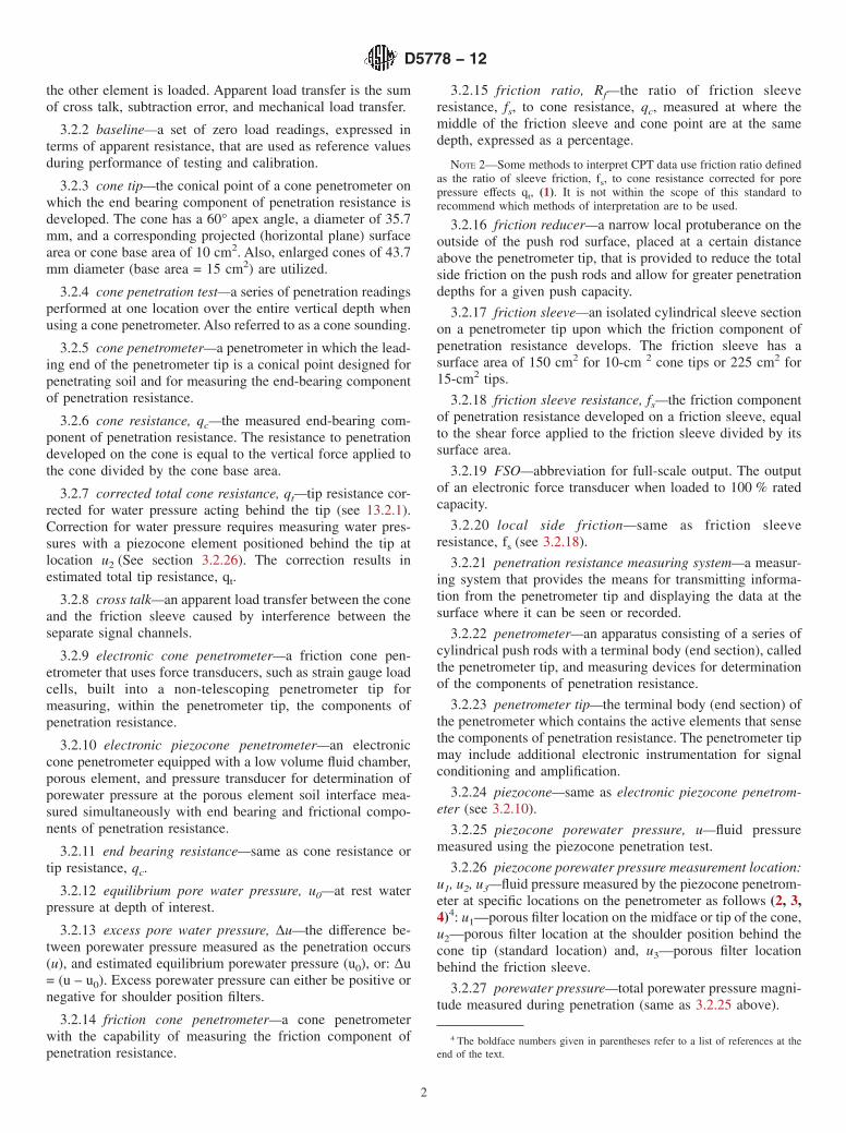
Designation: D5778 - 12 Standard Test Method for Electronic Friction Cone and Piezocone Penetration Testing of Soils 1 This standard is issued under the fixed designation D5778; the number immediately following the designation indicates the year of original adoption or, in the case of revision, the year of last revision. A number in parentheses indicates the year of last reapproval. A superscript epsilon (´) indicates an editorial change since the last revision or reapproval. 1. Scope* 1.1 This test method covers the procedure for determining the point resistance during penetration of a conical-shaped penetrometer as it is advanced into subsurface soils at a steady rate. 1.2 This test method is also used to determine the frictional resistance of a cylindrical sleeve located behind the conical point as it is advanced through subsurface soils at a steady rate. 1.3 This test method applies to friction-cone penetrometers of the electric and electronic type. Field tests using mechanical-type penetrometers are covered elsewhere by Test Method D3441. 1.4 This test method can be used to determine porewater pressures developed during the penetration, thus termed piezo- cone. Porewater pressure dissipation, after a push, can also be monitored for correlation to time rate of consolidation and permeability. 1.5 Additional sensors, such as inclinometer, seismic geo- phones (Test Methods D7400), resistivity, electrical conductivity, dielectric, and temperature sensors, may be included in the penetrometer to provide useful information. The use of an inclinometer is highly recommended since it will provide information on potentially damaging situations during the sounding process. 1.6 Cone penetration test data can be used to interpret subsurface stratigraphy, and through use of site specific correlations, they can provide data on engineering properties of soils intended for use in design and construction of earthworks and foundations for structures. 1.7 The values stated in SI units are to be regarded as standard. Within Section 13 on Calculations, SI units are considered the standard. Other commonly used units such as the inch-pound system are shown in brackets. The various data reported should be displayed in mutually compatible units as agreed to by the client or user. Cone tip projected area is commonly referred to in square centimetres for convenience. The values stated in each system are not equivalents; therefore, each system shall be used independently of the other. NOTE 1—This test method does not include hydraulic or pneumatic penetrometers. However, many of the procedural requirements herein could apply to those penetrometers. Also, offshore/marine CPT systems may have procedural differences because of the difficulties of testing in those environments (for example, tidal variations, salt water, waves). Mechanical CPT systems are covered under Test Method D3441. 1.8 This standard does not purport to address all of the safety concerns, if any, associated with its use. It is the responsibility of the user of this standard to establish appro- priate safety and health practices and determine the applica- bility of regulatory limitations prior to use. 2. Referenced Documents 2.1 ASTM Standards: 2 D653 Terminology Relating to Soil, Rock, and Contained Fluids D3441 Test Method for Mechanical Cone Penetration Tests of Soil (Withdrawn 2014) 3 D3740 Practice for Minimum Requirements for Agencies Engaged in Testing and/or Inspection of Soil and Rock as Used in Engineering Design and Construction D7400 Test Methods for Downhole Seismic Testing E4 Practices for Force Verification of Testing Machines 3. Terminology 3.1 Definitions: 3.1.1 Definitions are in accordance with Terminology Con- vention (D653). 3.2 Definitions of Terms Specific to This Standard: 3.2.1 apparent load transfer—apparent resistance measured on either the cone or friction sleeve of an electronic cone penetrometer while that element is in a no-load condition but 1 This test method is under the jurisdiction of ASTM Committee D18 on Soil and Rock and is the direct responsibility of Subcommittee D18.02 on Sampling and Related Field Testing for Soil Evaluations. Current edition approved Jan. 1, 2012. Published February 2012. Originally approved in 1995. Last previous edition approved in 2007 as D5778–07. DOI: 10.1520/D5778-12. 2 For referenced ASTM standards, visit the ASTM website, www.astm.org, or contact ASTM Customer Service at [email protected]. For Annual Book of ASTM Standards volume information, refer to the standard’s Document Summary page on the ASTM website. 3 The last approved version of this historical standard is referenced on www.astm.org. *A Summary of Changes section appears at the end of this standard Copyright © ASTM International, 100 Barr Harbor Drive, PO Box C700, West Conshohocken, PA 19428-2959. United States 1
Transcript of Designation: D5778 12bolandist.com/media/6441/astm-d5778-12.pdf · Standard Test Method for...
Designation: D5778 − 12
Standard Test Method forElectronic Friction Cone and Piezocone Penetration Testingof Soils1
This standard is issued under the fixed designation D5778; the number immediately following the designation indicates the year oforiginal adoption or, in the case of revision, the year of last revision. A number in parentheses indicates the year of last reapproval. Asuperscript epsilon (´) indicates an editorial change since the last revision or reapproval.
1. Scope*
1.1 This test method covers the procedure for determiningthe point resistance during penetration of a conical-shapedpenetrometer as it is advanced into subsurface soils at a steadyrate.
1.2 This test method is also used to determine the frictionalresistance of a cylindrical sleeve located behind the conicalpoint as it is advanced through subsurface soils at a steady rate.
1.3 This test method applies to friction-cone penetrometersof the electric and electronic type. Field tests usingmechanical-type penetrometers are covered elsewhere by TestMethod D3441.
1.4 This test method can be used to determine porewaterpressures developed during the penetration, thus termed piezo-cone. Porewater pressure dissipation, after a push, can also bemonitored for correlation to time rate of consolidation andpermeability.
1.5 Additional sensors, such as inclinometer, seismic geo-phones (Test Methods D7400), resistivity, electricalconductivity, dielectric, and temperature sensors, may beincluded in the penetrometer to provide useful information.The use of an inclinometer is highly recommended since it willprovide information on potentially damaging situations duringthe sounding process.
1.6 Cone penetration test data can be used to interpretsubsurface stratigraphy, and through use of site specificcorrelations, they can provide data on engineering properties ofsoils intended for use in design and construction of earthworksand foundations for structures.
1.7 The values stated in SI units are to be regarded asstandard. Within Section 13 on Calculations, SI units areconsidered the standard. Other commonly used units such asthe inch-pound system are shown in brackets. The various datareported should be displayed in mutually compatible units as
agreed to by the client or user. Cone tip projected area iscommonly referred to in square centimetres for convenience.The values stated in each system are not equivalents; therefore,each system shall be used independently of the other.
NOTE 1—This test method does not include hydraulic or pneumaticpenetrometers. However, many of the procedural requirements hereincould apply to those penetrometers. Also, offshore/marine CPT systemsmay have procedural differences because of the difficulties of testing inthose environments (for example, tidal variations, salt water, waves).Mechanical CPT systems are covered under Test Method D3441.
1.8 This standard does not purport to address all of thesafety concerns, if any, associated with its use. It is theresponsibility of the user of this standard to establish appro-priate safety and health practices and determine the applica-bility of regulatory limitations prior to use.
2. Referenced Documents
2.1 ASTM Standards:2
D653 Terminology Relating to Soil, Rock, and ContainedFluids
D3441 Test Method for Mechanical Cone Penetration Testsof Soil (Withdrawn 2014)3
D3740 Practice for Minimum Requirements for AgenciesEngaged in Testing and/or Inspection of Soil and Rock asUsed in Engineering Design and Construction
D7400 Test Methods for Downhole Seismic TestingE4 Practices for Force Verification of Testing Machines
3. Terminology
3.1 Definitions:3.1.1 Definitions are in accordance with Terminology Con-
vention (D653).3.2 Definitions of Terms Specific to This Standard:3.2.1 apparent load transfer—apparent resistance measured
on either the cone or friction sleeve of an electronic conepenetrometer while that element is in a no-load condition but
1 This test method is under the jurisdiction of ASTM Committee D18 on Soil andRock and is the direct responsibility of Subcommittee D18.02 on Sampling andRelated Field Testing for Soil Evaluations.
Current edition approved Jan. 1, 2012. Published February 2012. Originallyapproved in 1995. Last previous edition approved in 2007 as D5778–07. DOI:10.1520/D5778-12.
2 For referenced ASTM standards, visit the ASTM website, www.astm.org, orcontact ASTM Customer Service at [email protected]. For Annual Book of ASTMStandards volume information, refer to the standard’s Document Summary page onthe ASTM website.
3 The last approved version of this historical standard is referenced onwww.astm.org.
*A Summary of Changes section appears at the end of this standard
Copyright © ASTM International, 100 Barr Harbor Drive, PO Box C700, West Conshohocken, PA 19428-2959. United States
1
the other element is loaded. Apparent load transfer is the sumof cross talk, subtraction error, and mechanical load transfer.
3.2.2 baseline—a set of zero load readings, expressed interms of apparent resistance, that are used as reference valuesduring performance of testing and calibration.
3.2.3 cone tip—the conical point of a cone penetrometer onwhich the end bearing component of penetration resistance isdeveloped. The cone has a 60° apex angle, a diameter of 35.7mm, and a corresponding projected (horizontal plane) surfacearea or cone base area of 10 cm2. Also, enlarged cones of 43.7mm diameter (base area = 15 cm2) are utilized.
3.2.4 cone penetration test—a series of penetration readingsperformed at one location over the entire vertical depth whenusing a cone penetrometer. Also referred to as a cone sounding.
3.2.5 cone penetrometer—a penetrometer in which the lead-ing end of the penetrometer tip is a conical point designed forpenetrating soil and for measuring the end-bearing componentof penetration resistance.
3.2.6 cone resistance, qc—the measured end-bearing com-ponent of penetration resistance. The resistance to penetrationdeveloped on the cone is equal to the vertical force applied tothe cone divided by the cone base area.
3.2.7 corrected total cone resistance, qt—tip resistance cor-rected for water pressure acting behind the tip (see 13.2.1).Correction for water pressure requires measuring water pres-sures with a piezocone element positioned behind the tip atlocation u2 (See section 3.2.26). The correction results inestimated total tip resistance, qt.
3.2.8 cross talk—an apparent load transfer between the coneand the friction sleeve caused by interference between theseparate signal channels.
3.2.9 electronic cone penetrometer—a friction cone pen-etrometer that uses force transducers, such as strain gauge loadcells, built into a non-telescoping penetrometer tip formeasuring, within the penetrometer tip, the components ofpenetration resistance.
3.2.10 electronic piezocone penetrometer—an electroniccone penetrometer equipped with a low volume fluid chamber,porous element, and pressure transducer for determination ofporewater pressure at the porous element soil interface mea-sured simultaneously with end bearing and frictional compo-nents of penetration resistance.
3.2.11 end bearing resistance—same as cone resistance ortip resistance, qc.
3.2.12 equilibrium pore water pressure, u0—at rest waterpressure at depth of interest.
3.2.13 excess pore water pressure, ∆u—the difference be-tween porewater pressure measured as the penetration occurs(u), and estimated equilibrium porewater pressure (u0), or: ∆u= (u – u0). Excess porewater pressure can either be positive ornegative for shoulder position filters.
3.2.14 friction cone penetrometer—a cone penetrometerwith the capability of measuring the friction component ofpenetration resistance.
3.2.15 friction ratio, Rf—the ratio of friction sleeveresistance, fs, to cone resistance, qc, measured at where themiddle of the friction sleeve and cone point are at the samedepth, expressed as a percentage.
NOTE 2—Some methods to interpret CPT data use friction ratio definedas the ratio of sleeve friction, fs, to cone resistance corrected for porepressure effects qt, (1). It is not within the scope of this standard torecommend which methods of interpretation are to be used.
3.2.16 friction reducer—a narrow local protuberance on theoutside of the push rod surface, placed at a certain distanceabove the penetrometer tip, that is provided to reduce the totalside friction on the push rods and allow for greater penetrationdepths for a given push capacity.
3.2.17 friction sleeve—an isolated cylindrical sleeve sectionon a penetrometer tip upon which the friction component ofpenetration resistance develops. The friction sleeve has asurface area of 150 cm2 for 10-cm 2 cone tips or 225 cm2 for15-cm2 tips.
3.2.18 friction sleeve resistance, fs—the friction componentof penetration resistance developed on a friction sleeve, equalto the shear force applied to the friction sleeve divided by itssurface area.
3.2.19 FSO—abbreviation for full-scale output. The outputof an electronic force transducer when loaded to 100 % ratedcapacity.
3.2.20 local side friction—same as friction sleeveresistance, fs (see 3.2.18).
3.2.21 penetration resistance measuring system—a measur-ing system that provides the means for transmitting informa-tion from the penetrometer tip and displaying the data at thesurface where it can be seen or recorded.
3.2.22 penetrometer—an apparatus consisting of a series ofcylindrical push rods with a terminal body (end section), calledthe penetrometer tip, and measuring devices for determinationof the components of penetration resistance.
3.2.23 penetrometer tip—the terminal body (end section) ofthe penetrometer which contains the active elements that sensethe components of penetration resistance. The penetrometer tipmay include additional electronic instrumentation for signalconditioning and amplification.
3.2.24 piezocone—same as electronic piezocone penetrom-eter (see 3.2.10).
3.2.25 piezocone porewater pressure, u—fluid pressuremeasured using the piezocone penetration test.
3.2.26 piezocone porewater pressure measurement location:u1, u2, u3—fluid pressure measured by the piezocone penetrom-eter at specific locations on the penetrometer as follows (2, 3,4)4: u1—porous filter location on the midface or tip of the cone,u2—porous filter location at the shoulder position behind thecone tip (standard location) and, u3—porous filter locationbehind the friction sleeve.
3.2.27 porewater pressure—total porewater pressure magni-tude measured during penetration (same as 3.2.25 above).
4 The boldface numbers given in parentheses refer to a list of references at theend of the text.
D5778 − 12
2
3.2.28 porewater pressure ratio parameter, Bq—the ratio ofexcess porewater pressure at the standard measurement loca-tion ∆u2, to corrected total cone resistance qt, minus the totalvertical overburden stress, σvo (see Eq 10).
3.2.29 push rods—the thick-walled tubes or rods used toadvance the penetrometer tip.
3.2.30 sleeve friction, sleeve, and friction resistance—sameas friction sleeve resistance.
3.2.31 subtraction error—an apparent load transfer from thecone to the friction sleeve of a subtraction type electronic conepenetrometer caused by minor voltage differences in responseto load between the two strain element cells.
3.3 Abbreviations:3.3.1 CPT—abbreviation for the cone penetration test.
3.3.2 PCPT (2, 3) or CPTu (4)—abbreviation for piezoconepenetration test (note: symbol “u” added for porewater pressuremeasurements).
3.3.3 CPTù—abbreviation for the piezocone penetration testwith dissipation phases of porewater pressures (ù).
3.3.4 SCPTu—abbreviation for seismic piezocone test TestMethods D7400 (includes one or more geophones to allowdownhole geophysical wave velocity measurements).
3.3.5 RCPTu—abbreviation for resistivity piezocone (in-cludes electrical conductivity or resistivity module).
4. Summary of Test Method
4.1 A penetrometer tip with a conical point having a 60°apex angle and a cone base area of 10 or 15 cm2 is advancedthrough the soil at a constant rate of 20 mm/s. The force on theconical point (cone) required to penetrate the soil is measuredby electrical methods, at a minimum of every 50 mm ofpenetration. Improved resolution may often be obtained at 20-or 10-mm interval readings. Stress is calculated by dividing themeasured force (total cone force) by the cone base area toobtain cone resistance, qc.
4.2 A friction sleeve is present on the penetrometer imme-diately behind the cone tip, and the force exerted on the frictionsleeve is measured by electrical methods at a minimum ofevery 50 mm of penetration. Stress is calculated by dividingthe measured axial force by the surface area of the frictionsleeve to determine sleeve resistance, fs.
4.3 Most modern penetrometers are capable of registeringpore water pressure induced during advancement of the pen-etrometer tip using an electronic pressure transducer. Thesepenetrometers are called “piezocones.” The piezocone is ad-vanced at a rate of 20 mm/s, and readings are taken at aminimum of every 50 mm of penetration. The dissipation ofeither positive or negative excess porewater pressure can bemonitored by stopping penetration, unloading the push rod, andrecording porewater pressure as a function of time. Whenporewater pressure becomes constant it is measuring theequilibrium value (designated u0) or piezometric level at thatdepth.
5. Significance and Use
5.1 Tests performed using this test method provide a de-tailed record of cone resistance which is useful for evaluationof site stratigraphy, homogeneity and depth to firm layers,voids or cavities, and other discontinuities. The use of a frictionsleeve and porewater pressure element can provide an estimateof soil classification, and correlations with engineering prop-erties of soils. When properly performed at suitable sites, thetest provides a rapid means for determining subsurface condi-tions.
5.2 This test method provides data used for estimatingengineering properties of soil intended to help with the designand construction of earthworks, the foundations for structures,and the behavior of soils under static and dynamic loads.
5.3 This method tests the soil in-situ and soil samples arenot obtained. The interpretation of the results from this testmethod provides estimates of the types of soil penetrated.Engineers may obtain soil samples from parallel borings forcorrelation purposes but prior information or experience maypreclude the need for borings.
NOTE 3—The quality of the results produced by this standard isdependent on the competence of the personal performing the test, and thesuitability of the equipment and facilities used. Agencies that meet thecriteria of Practice D3740 are generally considered capable of competentand objective testing/sampling/inspection/etc. Users of this standard arecautioned that compliance with Practice D3740 does not in itself assurereliable results. Reliable results depend on many factors and PracticeD3740 provides a means of evaluating some of those factors.
6. Interferences
6.1 Refusal, deflection, or damage to the penetrometer mayoccur in coarse grained soil deposits with maximum particlesizes that approach or exceed the diameter of the cone.
6.2 Partially lithified and lithified deposits may causerefusal, deflection, or damage to the penetrometer.
6.3 Standard push rods can be damaged or broken underextreme loadings. The amount of force that push rods are ableto sustain is a function of the unrestrained length of the rodsand the weak links in the push rod-penetrometer tip string suchas push rod joints and push rod-penetrometer tip connections.The force at which rods may break is a function of theequipment configuration and ground conditions during pen-etration. Excessive rod deflection is the most common causefor rod breakage.
7. Apparatus
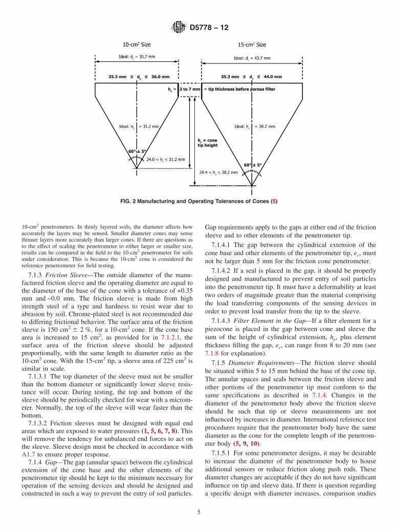
7.1 Friction Cone Penetrometer—The penetrometer tipshould meet requirements as given below and in 10.1. In aconventional friction-type cone penetrometer, the forces at thecone tip and friction sleeve are measured by two load cellswithin the penetrometer. Either independent load cells orsubtraction-type penetrometers are acceptable for use (Fig. 1).
7.1.1 In the subtraction-type penetrometer, the cone andsleeve both produce compressive forces on the load cells. Theload cells are joined together in such a manner that the cellnearest the cone (the “C” cell in Fig. 1b) measures thecompressive force on the cone while the second cell (the“C + S” cell in Fig. 1b) measures the sum of the compressive
D5778 − 12
3

forces on both the cone and friction sleeve. The compressiveforce from the friction sleeve portion is computed then bysubtraction. This cone design is common in industry because ofits rugged design. This design forms the basis for minimumperformance requirements for electronic penetrometers.
7.1.1.1 Alternative designs have separate and non-dependent load cells separate for tip and sleeve. For instance,in Fig. 1a, the cone penetrometer tip produces a compressionforce on the cone load cell (the “C” cell in Fig. 1a) while thefriction sleeve produces a tensile force on the independentfriction sleeve load cell (the “S” cell). Designs are alsoavailable where both the tip and sleeve load cells are indepen-dent and operate in compression (1). These penetrometerdesigns result in a higher degree of accuracy in friction sleevemeasurement, however, may be more susceptible to damageunder extreme loading conditions.
7.1.1.2 Typical general purpose cone penetrometers aremanufactured to full scale outputs (FSO) equivalent to netloads of 10 to 20 tons. Often, weak soils are the most criticalin an investigation program, and in some cases, very accuratefriction sleeve data may be required. To gain better resolution,the FSO can be lowered or the independent type penetrometerdesign can be selected. A low FSO subtraction cone mayprovide more accurate data than a standard FSO independenttype cone depending on such factors as system design andthermal compensation. If the FSO is lowered, this may placeelectrical components at risk if overloaded in stronger soils.Expensive preboring efforts may be required to avoid damagein these cases. The selection of penetrometer type and resolu-tion should consider such factors as practicality, availability,calibration requirements, cost, risk of damage, and preboringrequirements.
7.1.1.3 The user or client should select the cone designrequirements by consulting with experienced users or manu-
facturers. The need for a specific cone design depends on thedesign data requirements outlined in the exploration program.
7.1.1.4 Regardless of penetrometer type, the friction sleeveload cell system must operate in such a way that the system issensitive to only shear stresses applied to the friction sleeveand not to normal stresses.
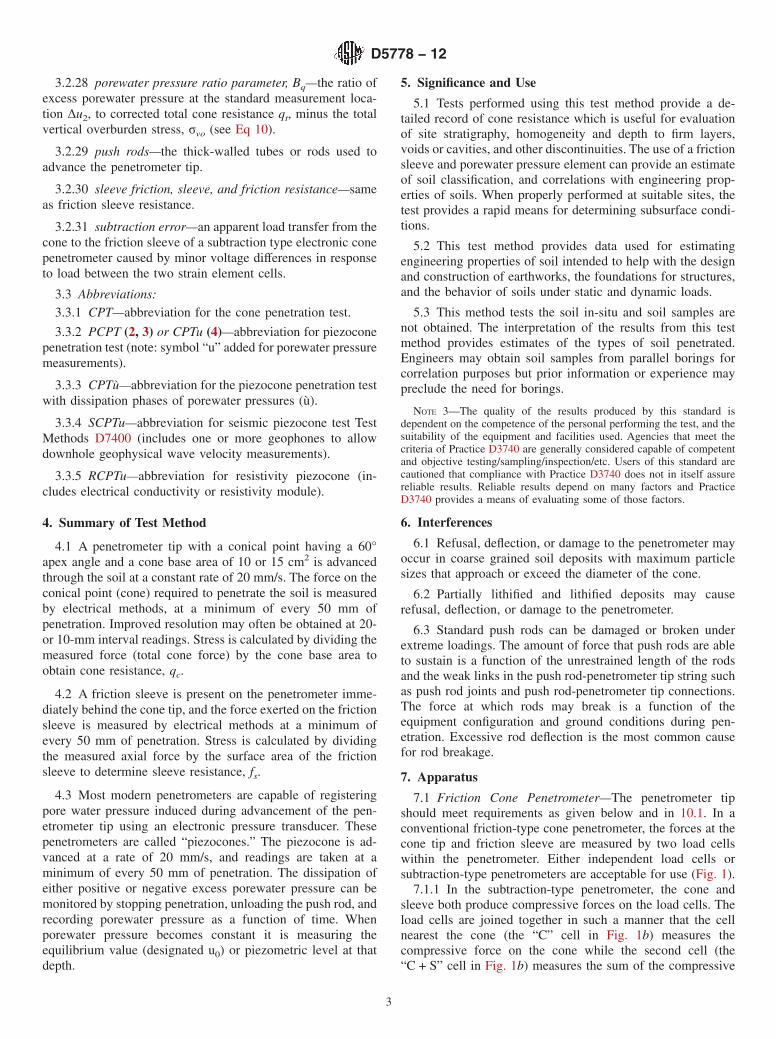
7.1.2 Cone—Nominal dimensions, with manufacturing andoperating tolerances, for the cone are shown on Fig. 2. Thecone has a diameter d = 35.7 mm, projected base areaAc = 1000 mm2, + 2 %–5 % with an apex angle of 60°. Acylindrical extension, he, of 5 mm should be located behind thebase of the cone to protect the outer edges of the cone basefrom excessive wear. The 10 cm2 cone is considered thereference standard for which results of other penetrometerswith proportionally scaled dimensions can be compared.
7.1.2.1 In certain cases, it may be desirable to increase thecone diameter in order to add room for sensors or increaseruggedness of the penetrometer. The standard increase is to abase diameter of 43.7 mm which provides a projected conebase area of 1500 mm2 while maintaining a 60° apex angle.Nominal dimensions, with manufacturing and operating toler-ances for the 15 cm2 cone, are shown in Fig. 2, based on theinternational guides (5).
7.1.2.2 The cone is made of high strength steel of a type andhardness suitable to resist wear due to abrasion by soil. Conetips which have worn to the operating tolerance shown in Fig.2 should be replaced. Piezocone tips should be replaced whenthe tip has worn appreciably (as shown) and the height of thecylindrical extension has reduced considerably (as shown).
NOTE 4—In some applications it may be desirable to scale the conediameter down to a smaller projected area. Cone penetrometers with 5 cm2
projected area find use in the field applications and even smaller sizes (1cm2) are used in the laboratory for research purposes. These cones shouldbe designed with dimensions scaled in direct proportion to standard
FIG. 1 Common Configurations for Electric Friction-Cone Penetrometers (1) Showing: (a) Compression-type Tip and Sleeve Load Cells,(b) Tension-type Sleeve Design, and (c) Subtraction-type Penetrometer
D5778 − 12
4
10-cm2 penetrometers. In thinly layered soils, the diameter affects howaccurately the layers may be sensed. Smaller diameter cones may sensethinner layers more accurately than larger cones. If there are questions asto the effect of scaling the penetrometer to either larger or smaller size,results can be compared in the field to the 10-cm2 penetrometer for soilsunder consideration. This is because the 10-cm2 cone is considered thereference penetrometer for field testing.
7.1.3 Friction Sleeve—The outside diameter of the manu-factured friction sleeve and the operating diameter are equal tothe diameter of the base of the cone with a tolerance of +0.35mm and −0.0 mm. The friction sleeve is made from highstrength steel of a type and hardness to resist wear due toabrasion by soil. Chrome-plated steel is not recommended dueto differing frictional behavior. The surface area of the frictionsleeve is 150 cm2 6 2 %, for a 10-cm2 cone. If the cone basearea is increased to 15 cm2, as provided for in 7.1.2.1, thesurface area of the friction sleeve should be adjustedproportionally, with the same length to diameter ratio as the10-cm2 cone. With the 15-cm2 tip, a sleeve area of 225 cm2 issimilar in scale.
7.1.3.1 The top diameter of the sleeve must not be smallerthan the bottom diameter or significantly lower sleeve resis-tance will occur. During testing, the top and bottom of thesleeve should be periodically checked for wear with a microm-eter. Normally, the top of the sleeve will wear faster than thebottom.
7.1.3.2 Friction sleeves must be designed with equal endareas which are exposed to water pressures (1, 5, 6, 7, 8). Thiswill remove the tendency for unbalanced end forces to act onthe sleeve. Sleeve design must be checked in accordance withA1.7 to ensure proper response.
7.1.4 Gap—The gap (annular space) between the cylindricalextension of the cone base and the other elements of thepenetrometer tip should be kept to the minimum necessary foroperation of the sensing devices and should be designed andconstructed in such a way to prevent the entry of soil particles.
Gap requirements apply to the gaps at either end of the frictionsleeve and to other elements of the penetrometer tip.
7.1.4.1 The gap between the cylindrical extension of thecone base and other elements of the penetrometer tip, ec, mustnot be larger than 5 mm for the friction cone penetrometer.
7.1.4.2 If a seal is placed in the gap, it should be properlydesigned and manufactured to prevent entry of soil particlesinto the penetrometer tip. It must have a deformability at leasttwo orders of magnitude greater than the material comprisingthe load transferring components of the sensing devices inorder to prevent load transfer from the tip to the sleeve.
7.1.4.3 Filter Element in the Gap—If a filter element for apiezocone is placed in the gap between cone and sleeve thesum of the height of cylindrical extension, he, plus elementthickness filling the gap, ec, can range from 8 to 20 mm (see7.1.8 for explanation).
7.1.5 Diameter Requirements—The friction sleeve shouldbe situated within 5 to 15 mm behind the base of the cone tip.The annular spaces and seals between the friction sleeve andother portions of the penetrometer tip must conform to thesame specifications as described in 7.1.4. Changes in thediameter of the penetrometer body above the friction sleeveshould be such that tip or sleeve measurements are notinfluenced by increases in diameter. International reference testprocedures require that the penetrometer body have the samediameter as the cone for the complete length of the penetrom-eter body (5, 9, 10).
7.1.5.1 For some penetrometer designs, it may be desirableto increase the diameter of the penetrometer body to houseadditional sensors or reduce friction along push rods. Thesediameter changes are acceptable if they do not have significantinfluence on tip and sleeve data. If there is question regardinga specific design with diameter increases, comparison studies
FIG. 2 Manufacturing and Operating Tolerances of Cones (5)
D5778 − 12
5
can be made to a penetrometer with constant diameter. Infor-mation on diameters of the complete penetrometer body shouldbe reported.
NOTE 5—The effects caused by diameter changes of the penetrometeron tip and sleeve resistance are dependent on the magnitude of diameterincrease and location on the penetrometer body. Most practitioners feelthat diameter increases equivalent to addition of a friction reducer witharea increases of 15 to 20 % should be restricted to a location at least eightto ten cone diameters behind the friction sleeve.
7.1.6 The axis of the cone, the friction sleeve (if included),and the body of the penetrometer tip must be coincident.
7.1.7 Force Sensing Devices—The typical force sensingdevice is a strain gauge load cell that contains temperaturecompensated bonded strain gages. The configuration andlocation of strain gages should be such that measurements arenot influenced by possible eccentricity of loading.
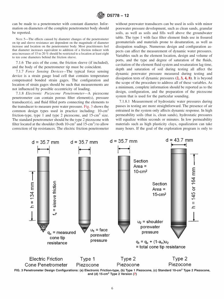
7.1.8 Electronic Piezocone Penetrometer—A piezoconepenetrometer can contain porous filter element(s), pressuretransducer(s), and fluid filled ports connecting the elements tothe transducer to measure pore water pressure. Fig. 3 shows thecommon design types used in practice including: 10-cm2
friction-type, type 1 and type 2 piezocone, and 15-cm2 size.The standard penetrometer should be the type 2 piezocone withfilter located at the shoulder (both 10-cm2 and 15-cm2) to allowcorrection of tip resistances. The electric friction penetrometer
without porewater transducers can be used in soils with minorporewater pressure development, such as clean sands, granularsoils, as well as soils and fills well above the groundwatertable. The type 1 with face filter element finds use in fissuredgeomaterials and materials prone to desaturation, as well asdissipation readings. Numerous design and configuration as-pects can affect the measurement of dynamic water pressures.Variables such as the element location, design and volume ofports, and the type and degree of saturation of the fluids,cavitation of the element fluid system and resaturation lag time,depth and saturation of soil during testing all affect thedynamic porewater pressure measured during testing anddissipation tests of dynamic pressures (2, 3, 4, 8). It is beyondthe scope of the procedure to address all of these variables. Asa minimum, complete information should be reported as to thedesign, configuration, and the preparation of the piezoconesystem that is used for the particular sounding.
7.1.8.1 Measurement of hydrostatic water pressures duringpauses in testing are more straightforward. The presence of airentrained in the system only affects dynamic response. In highpermeability soils (that is, clean sands), hydrostatic pressureswill equalize within seconds or minutes. In low permeabilitymaterials such as high plasticity clays, equalization can takemany hours. If the goal of the exploration program is only to
FIG. 3 Penetrometer Design Configurations: (a) Electronic Friction-type, (b) Type 1 Piezocone, (c) Standard 10-cm2 Type 2 Piezocone,and (d) 15-cm2 Type 2 Version (7)
D5778 − 12
6
acquire hydrostatic pressures in sands, some of the preparationprocedures for dynamic pressure measuring can be relaxed,such as deairing fluids.
7.1.8.2 The porewater pressure measurement locations ofthe porous element are limited to the face or tip of the cone, u1,directly behind the cylindrical extension of the base of thecone, u2, or behind the sleeve, u3. Some penetrometers used forresearch purposes may have multiple measurement locations.
7.1.8.3 There are several advantages to locating the porouselement immediately behind the tip of the cone in location u2,primarily the required correction of measured qc to total tipstress, qt, as detailed extensively (4-8). Also, the element is lesssubject to damage and abrasion, as well as fewer compress-ibility effects (4, 8). Elements located in the u2 location may besubject to cavitation at shallow depths in dense sands becausethe zone behind the height of cylindrical extension is a zone ofdilation in drained soils. Similar response can occur in stifffissured clays and crusts (4). Porewater pressure measurementsobtained at the u1 face location are more effective for com-pressibility determinations and layer detection, particularly infissured soils, but are more subject to wear (3, 11). At the u2
location, a minimum 2-mm cylindrical extension of the conetip (he) should be maintained for protection of the cone. Typicalfilter element thickness at all locations in the horizontal planeranges from 5 to 10 mm.
7.1.8.4 The miniature diaphragm-type electronic pressuretransducer is normally housed near the tip of the cone. Fordynamic pressure measurements, the filter and ports are filledwith deaired fluid to measure dynamic porewater pressureresponse. The volume of connecting ports to the transducershould be minimized to facilitate dynamic pressure response.These electronic transducers are normally very reliable,accurate, and linear in response. The transducer shall have aprecision of at least 614 kPa (62 psi). The porewater pressuretransducer must meet requirements given in 10.2.
7.1.8.5 Element—The element is a fine porous filter madefrom plastic, sintered steel or bronze, or ceramic. Typical poresize is between 20 to 200 microns (8, 11). Different materialshave different advantages. Smearing of metallic element open-ings by hard soil grains may reduce dynamic response of thesystem, thus normally not used for face elements but bestsuited for shoulder filter positions. Ceramic elements are verybrittle and may crack when loaded, but perform well on thecone face as they reduce compressibility concerns. Polypro-pylene plastic elements are most commonly used in practice,particularly at the shoulder. Plastic filters (as high-densitypolyethylene, HDPE, or high-density polypropylene, HDPP)may be inappropriate for environmental type CPTs wherecontaminant detection is sought. Typically, the filter element iswedged at the tip or midface (u1) location, or located at theshoulder in the gap immediately above the cone extension(designated u2) location. At these locations, it is important todesign the penetrometer such that compression of the filterelements is minimized.
7.1.8.6 Fluids for Saturation—Glycerine, or alternativelysilicone oil, is most often used for deairing elements fordynamic response. These stiff viscous oils have less tendencyto cavitate, although cavitation may be controlled by the
effective pore size of the element mounting surfaces. Water canbe used for the fluid if the entire sounding will be submerged,or if dynamic response is not important. The fluids are deairedusing procedures described in 11.2.
7.2 Measuring System—The signals from the penetrometertransducers are to be displayed at the surface during testing asa continuously updated plot against depth. The data are also tobe recorded electronically for subsequent processing. Elec-tronic recording shall be digital and use at least twelve bit (onepart in 4096) resolution in the analog to digital conversion,although 16-bit resolution and higher may be preferable in verysoft ground. Either magnetic (disk or tape) or optical (disk)non-volatile storage may be used. In analog systems, thetemperature stability and accuracy of the A-to-D convertershall be such that the overall cone-transmission-recordingsystem complies with calibration requirements set forth in theannex.
7.2.1 Use of analog systems is acceptable but the systemresolution may be lower than requirements in the annex andSection 10. Use of an analog recorder as a supplement todigital system is advantageous because it can provide systembackup.
NOTE 6—Depending upon the equipment, data stored digitally onmagnetic drives, tapes, floppy disks, or other media are often used. Thedata files should include project, location, operator, and data formatinformation (for example, channel, units, corrected or uncorrected, etc.) sothat the data can be understood when reading the file with a text editor.
7.3 Push Rods—Steel rods are required having a crosssectional area adequate to sustain, without buckling, the thrustrequired to advance the penetrometer tip. For penetrometersusing electrical cables, the cable is prestrung through the rodsprior to testing. Push rods are supplied in 1-meter lengths. Thepush rods must be secured together to bear against each otherat the joints and form a rigid-jointed string of push rods. Thedeviation of push rod alignment from a straight axis should beheld to a minimum, especially in the push rods near thepenetrometer tip, to avoid excessive directional penetrometerdrift. Generally, when a 1-m long push rod is subjected to apermanent circular bending resulting in 1 to 2 mm of centeraxis rod shortening, the push rod should be discarded. Thiscorresponds to a horizontal deflection of 2 to 3 mm at thecenter of bending. The locations of push rods in the stringshould be varied periodically to avoid permanent curvature.
7.3.1 For the 10-cm2 penetrometer, standard 20-metric tonhigh tensile strength steel push rods are 36-mm outsidediameter, 16-mm inside diameter, and have a mass per unitlength of 6.65 kg/m. For 15-cm2 penetrometers, the test may bepushed with 44.5-mm outside diameter rods or with standardrods used for the 10-cm2 penetrometer.
7.4 Friction Reducer—Friction reducers are normally usedon the push rods to reduce rod friction. If a friction reducer isused, it should be located on the push rods no closer than 0.5m behind the base of the cone. Friction reducers, that increasepush rod outside diameter by approximately 25 %, are typicallyused for 10-cm2 cones. If a 15-cm2 penetrometer is advancedwith 36-mm push rods there may be no need for frictionreducers since the penetrometer itself will open a larger hole.
D5778 − 12
7

The type, size, amount, and location of friction reducer(s) usedduring testing must be reported.
7.5 Thrust Machine and Reaction—The thrust machine willprovide a continuous stroke, preferably over a distance greaterthan 1 m. The thrust machine should be capable of adjustingpush direction through the use of a leveling system such thatpush initiates in a vertical orientation. The machine mustadvance the penetrometer tip and push rods at a smooth,constant rate (see 12.1.2) while the magnitude of thrust canfluctuate. The thrust machine must be anchored or ballasted, orboth, so that it provides the necessary reaction for the pen-etrometer and does not move relative to the soil surface duringthrust.
NOTE 7—Cone penetration soundings usually require thrust capabilitiesranging from 100 to 200 kN (11 to 22 tons) for full capacity. High massballasted vehicles can cause soil surface deformations which may affectpenetrometer resistance(s) measured in near surface layers. Anchored orballasted vehicles, or both, may induce changes in ground surfacereference level. If these conditions are evident, they should be noted inreports.
7.6 Other Sensing Devices—Other sensing devices can beincluded in the penetrometer body to provide additionalinformation during the sounding. These instruments are nor-mally read at the same continuous rate as tip, sleeve, andporewater pressure sensors, or alternatively, during pauses inthe push (often at 1-m rod breaks). Typical sensors areinclinometer, temperature, resistivity (or its reciprocal, electri-cal conductivity), or seismic sensors, such as geophones thatcan be used to obtain downhole shear wave velocity. Thesesensors should be calibrated if their use is critical to theinvestigation program. The use of an inclinometer is highlyrecommended since it will provide information on potentiallydamaging situations during the sounding process. An inclinom-eter can provide a useful depth reliability check because itprovides information on verticality. The configuration andmethods of operating such sensors should be reported.
8. Reagents and Materials
8.1 O-Ring Compound—A petroleum or silicon compoundfor facilitating seals with O-rings. Use of silicon compoundsmay impede repair of strain gages if the strain gauge surface isexposed to the compound.
8.2 Glycerine, or CHOH(CH2OH)2, for use in porewaterpressure measurement systems. Approximately 95 % pureglycerine can be procured from most drug stores.
8.3 Silicone Oil (or fluid), for use in porewater pressuremeasurement systems. This material is available in varyingviscosities ranging from 1400 to 10 000 CP.
NOTE 8—Detailed comparisons and discussions on the use of thesefluids can be found elsewhere (8, 11).
9. Hazards
9.1 Technical Precautions—General:9.1.1 Use of penetrometer components that do not meet
required tolerances or show visible signs of non-symmetricwear can result in erroneous penetration resistance data.
9.1.2 The application of thrust in excess of rated capacity ofthe equipment can result in damage to equipment (see Section6).
9.1.3 A cone sounding must not be performed any closerthan 25 borehole diameters from any existing unbackfilled oruncased bore hole.
9.1.4 When performing cone penetration testing in preboredholes, an estimate of the depth below the prebored depth whichis disturbed by drilling, should be made and penetrationresistance data obtained in this zone should be noted. Usually,this depth of disturbance is assumed to be equal to at least threeborehole diameters.
9.1.5 Significant bending of the push rods can influencepenetration resistance data. The use of a tubular rod guide isrecommended at the base of the thrust machine and also inprebored holes to help prevent push rod bending.
9.1.6 Push rods not meeting requirements of 7.3 may resultin excessive directional penetrometer drift and possibly unre-liable penetration resistance values.
9.1.7 Passing through or alongside obstructions may deflectthe penetrometer and induce directional drift. Note any indi-cations of encountering such obstructions, such as gravels, andbe alert for possible subsequent improper penetrometer tipoperation.
9.1.8 If the proper rate of advance of the penetrometer is notmaintained for the entire stroke through the measurementinterval, penetration resistance data will be erroneous.
9.2 Technical Precautions—Electronic Friction Cone Pen-etrometer:
9.2.1 Failure of O-ring seals can result in damage to orinaccurate readings from electronic transducers. The O-ringseals should be inspected regularly, after each sounding, foroverall condition, cleanliness and watertightness.
9.2.2 Soil ingress between different elements of a penetrom-eter tip can result in unreliable data. Specifically, soil ingresswill detrimentally affect sleeve resistance data. Seals should beinspected after each sounding, maintained regularly, and re-placed when necessary. If very accurate sleeve resistance datais required, it is recommended to clean all seals after eachsounding.
9.2.3 Electronic cone penetrometer tips should be tempera-ture compensated. If extreme temperatures outside of the rangeestablished in A1.3.3 are to be encountered, the penetrometershould be checked for the required temperature range toestablish they can meet the calibration requirements. Also,harsh environments may severely affect the data acquisitionsystem of power supplies, notebook or field computers, andother electronics.
9.2.4 If the shift in baseline reading after extracting thepenetrometer tip from the soil is so large that the conditions ofaccuracy as defined in 10.1.2.1 are no longer met, penetrationresistance data should be noted as unreliable. If baselinereadings do not conform to allowable limits established byaccuracy requirements in 10.1.2.1, the penetrometer tip mustbe repaired, and recalibrated or replaced.
9.2.5 Electronic friction cone penetrometers having unequalend areas on their friction sleeves can yield erroneous fs
D5778 − 12
8
readings because of dynamic porewater pressures acting un-evenly on the sleeve (1, 5, 6, 8). Friction sleeve design shouldbe checked in accordance with A1.7 to ensure balancedresponse. The response is also dependent on location of waterseals. If O-ring water seals are damaged during testing, andsleeve data appear affected, the sounding data should be notedas unreliable and the seals should be repaired.
9.3 Piezocone Penetrometer—The electronic piezoconepenetrometer tip measures pore water pressures on the exteriorof the penetrometer tip by transferring the pressure through ade-aired fluid system to a pressure transducer in the interior ofthe tip. For proper dynamic response, the measurement system(consisting of fluid ports and porous element) must be com-pletely saturated prior to testing. Entrained air must be re-moved from the fluid-filled system or porewater pressurefluctuation during penetrometer tip advancement will be incor-rect due to response lag from compression of air bubbles (see11.2, 12.3.2, and 12.3.3). For soundings where dynamicresponse is important, the prepared filter elements should bereplaced after every sounding.
10. Calibration and Standardization
10.1 Electronic Friction Cone Penetrometers:
10.1.1 The requirements for newly manufactured or re-paired cone penetrometers are of importance. Newly manufac-tured or repaired electronic cone penetrometers are to bechecked to meet the minimum calibration requirements de-scribed in the annex. These calibrations include load tests,thermal tests, and mechanical tests for effects of imbalancedhydrostatic forces. Calibration procedures and requirementsgiven in the annex are for subtraction-type cone penetrometers.Calibration requirements for independent-type cone penetrom-eters should equal or exceed those requirements. The calibra-tion records must be certified as correct by a registeredprofessional engineer or other responsible engineer withknowledge and experience in materials testing for qualityassurance. Applied forces or masses must be traceable tocalibration standard forces or masses retained by the NationalInstitute of Standards and Technology (NIST), formerly theNational Bureau of Standards. For description of calibrationterms and methods for calibrating, refer to the annex.
10.1.2 Baseline Readings—Baseline or zero-load readingsfor both cone and friction sleeve load cells and porewaterpressure transducers must be taken before and after eachsounding. The baseline reading is a reliable indicator of outputstability, temperature-induced apparent load, soil ingress, in-ternal friction, threshold sensitivity, and unknown loadingduring zero setting. Take the initial baseline reading afterwarming electrical circuits according to the manufacturer’sinstructions, generally for 15 to 30 min, and in a temperatureenvironment as close as possible to that of the material to besounded. If temperature is of concern, immerse the penetrom-eter tip in a bucket of fresh tap water, or insert the penetrometertip in the ground while electrically warming circuits to stabilizeits temperature and then extracted for rapid determination ofinitial baseline. After a sounding is completed, take a final
baseline. The change in initial and final baseline values shouldnot exceed 2 % FSO for the cone tip, sleeve, and pressuretransducer.
10.1.2.1 Maintain a continuous record of initial and finalbaselines during production testing. After each sounding,compare the final baseline to the initial baseline for agreementwithin the tolerances noted above. In some cases during heavyproduction testing where the cone is not disassembled andcleaned after each sounding, the initial baseline for the nextsounding can serve as the final baseline to the previoussounding as long as agreement is within allowable limits.
10.1.2.2 If the post sounding baseline shift exceeds abovecriteria, inspect the cone for damage by inspecting the tip andchecking to see that the sleeve can be rotated by hand. If thereis apparent damage, replace parts as required. Clean the coneand allow temperatures to equalize to presounding conditions,and obtain a new baseline. If this value agrees with the initialbaseline within the above criteria, a load range calibrationcheck is not required. If the pre and post baselines are still notwithin the above criteria then it is likely that the shift wascaused by an obstacle or obstruction and linearity should bechecked with a load range calibration.
10.1.2.3 If the baseline shift still exceeds the above criteria,perform a load range calibration as described in 10.1.2.1. If thecone load cell baseline shift exceeds 2 % FSO, the cone islikely damaged and will not meet load range criteria in10.1.2.2. Sleeve load cell baseline shifts for subtraction-typepenetrometers usually can exceed 2 % FSO and still meet loadrange criteria.
10.1.2.4 Report data for the sounding where unacceptablebaseline shift occurs as unreliable. In some cases it may beobvious where the damage occurred and data prior to that pointmay be considered reliable. The location where obviousdamage occurred should be clearly noted in reports.
10.1.3 Penetrometer Wear and Usage10.1.3.1 For penetrometers used regularly during
production, periodic load range checks should be performed.The inspection period can be based on production footage suchas once every lineal 3000 m (approx. 104 linear feet) ofsoundings. If field load range equipment is not available, thepenetrometer may be checked in the laboratory at the end of aproject.
10.1.3.2 For penetrometers that are used infrequently, aperiodic check may be based on time period, such as onceevery year. If a penetrometer has not been used for a longperiod of time, checking it before use is advisable.
10.1.3.3 For projects requiring a high level of qualityassurance, it may be required to do load range checks beforeand after the project.
10.1.3.4 Load range calibrations are required if the initialand final baselines for a sounding do not meet requirementsgiven in 10.1.2.1.
10.1.3.5 Records documenting the history of an individualpenetrometer should be maintained for evaluation of perfor-mance.
10.2 Porewater Pressure Transducer—Calibrate newlymanufactured or repaired transducers in accordance withrequirements in the annex. During production, the transducer
D5778 − 12
9
should be calibrated at regularly scheduled intervals andwhenever linear performance is suspect. The reference gaugecan be a Bourdon tube pressure gauge, or electronic pressuretransducer that is calibrated annually to NIST traceable loadingdevice (dead weight testing apparatus).
10.2.1 Prior to testing, baseline values or initial zeroing ofthe transducer is performed on the porewater pressure trans-ducer at ambient air pressures at the surface. Maintain recordsas to the baseline values for the transducer in similar fashion tothose for tip and sleeve resistance. If significant changes inbaseline values occur, normally 1 to 2 % FSO, perform loadrange tests to check for possible damage and nonlinearresponse.
10.3 Calibrations of Other Sensing Devices—Calibrationdata for other sensors in the penetrometer body may requirecalibrations using procedures similar to those given in theannex for load cells and pressure transducers. The need forcalibration depends on the requirements of the individualinvestigation program. For noncritical programs, the occur-rence of reasonable readings may be sufficient. In criticalprograms, it may be necessary to load the sensor through therange of interest with reference standards to ensure accuratereadings.
11. Conditioning
11.1 Power electronic cone penetrometer and data acquisi-tion systems for a minimum time period to stabilize electriccircuits before performing soundings. Power the system tomanufacturer’s recommendations prior to obtaining referencebaselines. For most electronic systems this time period is 15 to30 min.
11.2 Electronic piezocone penetrometer soundings requirespecial preparation of the transmitting fluid and porous ele-ments such that entrained air is removed from the system. Forsoundings where dynamic response is important, replace theprepared filter elements and the ports flushed after everysounding. Some of the techniques discussed below have beensuccessful for preparation of elements. Regardless of thetechniques used, report the equipment and methods.
11.2.1 Field or laboratory tests can be performed to evaluateassembled system response, if desired. Place the cone tip andelement in a pressurized chamber and subject to rapid pressurechange. Compare the response of the system to the appliedpressure changes and if responses match, the system is prop-erly prepared.
11.2.2 Place elements in a pure glycerine or silicone oil bathunder a vacuum of at least 90 % of one atmosphere (–90 kPa).Maintain vacuum until air bubble generation is reduced to aminimum. Application of ultrasonic vibration and low heat (T< 50°C) will assist in removal of air. Generally with use ofcombined vacuum, ultrasonic vibration, and low heat, filterelements can be deaired in about 4 h, although it is best toallow for 24 h to ensure best performance. Results will dependupon the viscosity of the fluid and pore size of the filterelement.
11.2.3 Elements can be prepared in water by boiling theelements while submerged in water for at least 4 h, althoughdamage may result from prolongued exposure in this approach(4).
11.2.4 Other Suitable Means—Report other techniques,such as commercially-purchased pre-saturated filter elementsthat are available, or grease-filled slot (1, 7).
11.2.5 Storage—Store prepared elements submerged in theprepared fluid until ready for use. Fill the containers andevacuate during storage. Allowable storage length depends onthe fluid. If elements are prepared in water they must bedeaired again one day after containers are opened and exposedto air. Elements stored in glycerine or silicone may be storedfor longer periods, up to several months, after storage contain-ers have been exposed to air.
12. Procedure
12.1 General Requirements:12.1.1 Prior to beginning a sounding, perform site surveys
to ensure hazards such as overhead and underground utilitieswill not be encountered. Position the thrust machine over thelocation of the sounding, and lower leveling jacks to raise themachine mass off the suspension system. Set the hydraulicrams of the penetrometer thrust system to as near vertical aspossible. The axis of the push rods must coincide with thethrust direction.
12.1.2 Set the hydraulic ram feed rate to advance thepenetrometer at a rate of 20 6 5 mm/s for all electronic conepenetrometers. This rate must be maintained during the entirestroke during downward advance of the rods while takingreadings.
12.1.3 Check push rods for straightness and permanentbending (See Section 7.3). Push rods are assembled andtightened by hand, but care must be taken and threads mayneed cleaning to ensure that the shoulders are tightly butted toprevent damage to the push rods. For electronic cone pen-etrometers using cables, the cable is prestrung through the pushrods. Add friction reducer to the string of push rods as required,usually the first push rod behind the penetrometer tip and otherrods as required.
12.1.4 Inspect penetrometer tips before and after soundingsfor damage, soil ingress, and wear. In very soft and sensitivesoils where accurate sleeve data is required, dismantle elec-tronic cone penetrometer tips and friction sleeves after eachsounding to clean and lubricate as required. If damage is foundafter a sounding, note and record this information on thesounding data record or report.
12.2 Friction Cone Penetrometers:12.2.1 Power up the penetrometer tip and data acquisition
system according to the manufacturer’s recommendations,typically 15 to 30 min, prior to use.
12.2.2 Obtain an initial baseline reading for the penetrom-eter in an unloaded condition at a temperature as close aspossible to ground conditions. Obtain baseline readings withthe penetrometer tip hanging freely in air or in water, out ofdirect sunlight. Compare baseline readings with the previousbaseline reading for the requirements given in 10.1.2.1. If
D5778 − 12
10
thermal stability needs to be assured, immerse the penetrom-eter tip in water at temperature close to ground; or perform aninitial short penetration test hole, stop penetration and allowthe penetrometer tip to reach soil temperature, and withdrawthe penetrometer.
12.2.3 Measure the depth at which readings were taken withan accuracy of at least 6100 mm from the ground surface.
12.2.4 Determine the cone resistance and friction sleeveresistance, continuously with depth, and record the data atintervals of depth not exceeding 50 mm.
12.2.5 During the progress of sounding, monitor tip andsleeve forces continuously for signs of proper operations. It ishelpful to monitor other indicators such as ram pressure orinclination to ensure that damage may not occur if highlyresistant layers or obstructions are encountered. Inclination is aparticularly useful indicator of imminent danger to the system(see 12.4).
12.2.6 At the end of a sounding, extract the penetrometertip, obtain a final set of baseline readings with the penetrometertip hanging freely in air or in water, and check them against theinitial baseline. Record initial and final baselines on alldocuments related to the sounding.
12.3 Electronic Piezocone Penetrometers:12.3.1 Power up the penetrometer tip and data acquisition
system according to the manufacturer’s recommendations,typically 15 to 30 min, prior to use.
12.3.2 Assemble the piezo elements with all fluid chamberssubmerged in the de-aired medium used to prepare the ele-ments. Flush all confined areas with fluid to remove airbubbles. Tighten the cone tip to effectively seal the flatsurfaces. For water fluid systems, protect the assembled systemfrom evaporation by enclosing the porous element inside afluid-filled plastic bag or cap sealed to the penetrometer tip.
12.3.3 If unsaturated soil is first penetrated and it is desiredto obtain accurate dynamic porewater pressure response oncebelow the ground water, it may be necessary to prebore orsound a pilot hole to the water table. In many cases, thepiezocone fluid system may cavitate during penetrationthrough unsaturated soil or in dilating sand layers below thewater table and this can adversely affect dynamic response. Asthe cone is advanced deeper, the saturation levels may recoveras air bubbles are driven back into solution according to BoylesLaw. Evaluation of proper interpretation of dynamic responserequires experience (4, 5, 8, 12). Pre-punching or pre-boringwith a two-level phase approach to soundings may helpalleviate desaturation problems.
12.3.4 Record baseline readings with the penetrometer tiphanging freely in air, or in water, out of direct sunlight.Compare baseline readings with reference baseline readings forrequirements given in 10.1.2.1 and 10.2. A baseline for theporewater pressure transducer is obtained immediately afterassembly to avoid evaporation effects. If evaporation is aproblem, temporarily immerse the penetrometer in a bucket ofwater until ready for baseline. Do not obtain transducerbaselines with protective caps or covers in place as these mayinduce pressure in the system. Note the pressure from thepressure transducer to see if it is a reasonable value for theequipment and assembly technique used.
12.3.5 Follow procedures similar to electric friction cone in12.2.4 – 12.2.6 with the addition of recording porewaterpressure readings.
12.3.6 Dissipation Tests—If dissipation tests are to be con-ducted during progress of the sounding, penetration is tempo-rarily stopped at the location of interest. If porewater pressuresare measured at the u2 or u3 locations, it is common practice torelease the force on the push rods. If porewater pressures aremeasured at the midface location u1, maintain the force on thepush rods. Record porewater pressure versus time duringconduct of the dissipation test. Monitor pressures until equi-librium porewater pressure is reached or 50 % of the initialexcess porewater pressure has dissipated. In fine grained soilsof very low conductivity, very long times may be required toreach the 50 % dissipation. Depending on the requirements ofthe program, and any concern of friction buildup on the pushrods, dissipation testing may be terminated prior to reachingthe 50 % level. Report dissipation test data as a record ofporewater pressure versus time, or more commonly, u versuslogarithm of time.
12.3.7 Hydrostatic Porewater Condition—If full dissipa-tions are carried out, then the porewater transducer willeventually record the hydrostatic condition, thus providing anevaluation of the position of the groundwater table or phreaticsurface.
12.4 Penetrometer Operation and Data Interpretation-Guidelines:
12.4.1 Directional Drift of Penetrometer:12.4.1.1 The penetrometer may drift directionally from
vertical alignment. Large deviations in inclination can createnonuniform loading and result in unreliable penetration resis-tance data. Reduce drift by accurately setting thrust alignmentand using push rods which meet tolerances given in 7.3.
12.4.1.2 Passing through or alongside obstructions such asboulders, cobbles, coarse gravel, soil concretions, thin rocklayers, or inclined dense layers will deflect the penetrometer tipand induce drifting. Note and record any indication of encoun-tering such obstructions, and be alert for possible subsequentimproper penetrometer tip operations as a sign of seriousdirectional drift.
12.4.1.3 Penetrometer inclination is typically monitored incone penetrometers. Impose limitations on inclination in thesystem to prevent damage to push rods and non-symmetricloading of the penetrometer tip. Generally, a 5° change ininclination over 1 m of penetration can impose detrimentalpush rod bending. Total drift of over 12° in 10 m of penetrationimposes non-symetric loading and possible unreliable penetra-tion resistance data.
12.4.2 Push Rod Addition Interruptions—Short durationinterruptions in the penetration rate during addition of eachnew push rod can affect initial cone and friction sleeve readingsat the beginning of the next push. If necessary, note and recordthe depths at which push rods are added and where long pausesmay have affected initial startup resistances.
12.4.3 Piezocone Porewater Pressure DissipationInterruptions—Porewater pressure dissipation studies, forwhich soundings are stopped and rod load is released forvarying time durations, can affect the initial cone, friction
D5778 − 12
11
sleeve, and dynamic porewater pressure readings at resump-tions of cone penetration. If dissipation tests are performed, beaware of possible rebound effects on initial excess porewaterpressures. Note and record the depth and duration for whichdissipation values are taken.
12.4.4 Interruptions Due to Obstructions—If obstructionsare encountered and normal advance of the sounding is stoppedto bore through the obstructions, obtain further penetrationresistance data only after the penetrometer tip has passedthrough the estimated zone of disturbance due to drilling. As analternative, readings may be continued without first making theadditional penetration and the disturbed zone evaluated fromthese data. Note and record the depth and thickness ofobstructions and disturbed zones in areas where obstructionsare drilled through.
12.4.5 Excessive Thrust Capacity—If excessive thrust pres-sure begins to impede the progress of the sounding, it may benecessary to withdraw and change friction reducers.Alternately, sometimes friction may be reduced by withdraw-ing the penetrometer and rods up to one third to one half of thepenetration depth and then repushing to depth at which thefriction caused stopping. Continue collection of sounding datafrom the point of stopping. Note and record the delay time anddepths to which the penetrometer was moved. Long delays andpauses may cause buildup of friction on the rods. Hold delaysto the minimum required to perform dissipation tests orequipment repairs.
12.4.5.1 If a high resistance layer is encountered, and thehydraulic thrust machine is physically moved duringpenetration, terminate the sounding. Another indicator ofreaching thrust capacity is the rebound of rods after they arereleased. The magnitude of rebound depends on the flexibilityof the thrust machine and the push rods. An operator mustbecome familiar with the safe deflection of the system anddecide when excessive deflections are being reached.
12.4.6 Unusual Occurrences—As data are recorded, it isimportant to note unusual occurrences in testing. When pen-etrating gravels, it is important to note “crunching” sounds thatmay occur when particle size and percentage of coarse particlesbegin to influence penetration. Note and report all occurrencesof coarse gravels.
12.5 Withdrawal:12.5.1 Withdraw the push rods and penetrometer tip as soon
as possible after attaining complete sounding depth.12.5.2 Upon complete withdrawal of the penetrometer,
inspect the penetrometer tip for proper operation. The frictionsleeve should be able to be rotated through 360° by handwithout detectable binding.
12.5.3 Record baseline readings with the penetrometer tiphanging freely in air, or in water, out of direct sunlight.Compare baseline readings with initial baseline reading forrequirements given in 10.1.2.1.
12.6 Hole Closure—In certain cases, it may be prudent orrequired by state law or specificiations, that the cone hole befilled, sealed, or grouted and closed after the sounding iscompleted. For example, in complex groundwater regimes,
hole closure should be made to protect the water aquifer.Details on various methods for hole closure are providedelsewhere (13).
13. Calculation
13.1 Friction Cone Penetrometers—Most electronic conepenetrometers in use at the present time measure a change involtage across a strain gauge element to determine change inlength of the strain element. Using known constitutive rela-tionships between stress and strain for the strain element, theapplied force may be determined for the cone or friction sleeve.The applied force may then be converted to stresses using thebasic equations given in 13.2 and 13.3. Since there are a widevariety of additional, optional measurements currently beingobtained with electronic cone penetrometers and new onesbeing continually developed, it is beyond the scope of thisprocedure to detail the makeup, adjustments, and calculationsfor these optional measurements.
13.2 Cone Resistance, qc—Required:
qc 5 Q c/Ac (1)
where:qc = cone resistance MPa (for example, ton/ft2, kgf/cm2, or
bar),Qc = force on cone kN (for example, ton, or kgf), andAc = cone base area, typically 10 cm2, or 15 cm2.
13.2.1 Corrected Total Cone Resistance (Required)—Calculation of corrected total cone resistance requires measure-ment of porewater pressures measured at the shoulder in the u2
position.
qt 5 qc1u2 ~1 2 an! (2)
where:qt = corrected total cone resistance, MPa (ton/ft2, kgf/cm2,
bar, or suitable units for stress),u 2 = porewater pressure generated immediately behind the
cone tip, kPa (for example, tsf, kgf/cm2, bar, or suitableunits for pressure), and
an = net area ratio (see A1.7).
13.2.1.1 The correction to total cone resistance is particu-larly important when porewater pressures are generated duringpenetration (for example, saturated clays, silts, and soils withappreciable fines). Generally, the correction is not so signifi-cant for CPTs in clean sands, dense to hard geomaterials, anddry soils. The correction is due to porewater pressures actingon opposing sides of both the face and joint annulus of the conetip (4, 1, 6, 8).
NOTE 9—In all cases, the total value qt should be used, substituted for(or both) qc, wherever possible. In no cases should qc be backdeterminedfrom qt for use in equations, charts, formulae, or other purposes. It isalways a forward procedure with corrected total qt to be preferred.
13.2.1.2 Empirical adjustment factors based on select soiltypes have been developed for some pressure elements in theu1 position, however these are not reliable. On a site-by-sitebasis, a relationship between u1 and u2 may be possible.
13.3 Friction Sleeve Resistance, fs—Required:
fs 5 Qs/As (3)
D5778 − 12
12

where:fs = friction sleeve resistance kPa (ton/ft2, kgf/cm2, bar, or
suitable units for stress),Qs = force on friction sleeve kN (ton, kgf, or suitable units
for force), andAs = area of friction sleeve, typically 150 cm2 for 10-cm2
tip, or 200 to 300 cm2 for larger 15-cm2 cones.NOTE 10—A corrected sleeve friction resistance may also be obtained
(ft), yet this requires both u2 and u3 measurements simulaneously (2, 3, 1,5, 6, 8). Thus, the raw fs has been accepted for practical reasons. Asimplified correction has been adopted by selected organizations (forexample, (8) ).
13.4 Friction Ratio, Rf—(Optional):
Rf 5 ~ f s/qc! ·100 (4)
where:Rf = friction ratio, %,fs = friction sleeve resistance kPa (ton/ft2, kgf/cm2, bar, or
suitable units for stress),qc = cone resistance kPa (ton/ft2, kgf/cm2, bar, or suitable
units for stress) (See Note 2 for use of qt), and100 = conversion from decimal to percent.
13.4.1 Determination of the friction ratio requires obtaininga cone resistance and friction sleeve resistance at the samepoint in the soil mass. The point of the cone is taken as thereference depth. Typically, a previous cone tip resistancereading at friction sleeve midpoint depth is used for thecalculations. For the 10-cm2 penetrometer, the standard offsetis 100 mm. If an offset other than midheight is used it must bereported.
NOTE 11—In some cases, if readings are compared at the same point ina soil mass which has alternating layers of soft and hard materials erraticfriction ratio data will be generated. This is because cone resistance issensed, to varying degrees, ahead of the cone. The erratic data may not berepresentative of soils actually present.
NOTE 12—The friction sleeve resistance and friction ratio obtainedfrom the mechanical friction cone penetrometers will differ considerablyfrom values obtained from electronic friction cone penetrometers. Whenusing soil classification charts that use Rf and qc, it is important to usecharts based on correlations for the type of penetrometer being used.
13.5 Porewater Pressure Data:13.5.1 SI metric units for reporting porewater pressure data
are kPa.13.5.2 Conversion of Measured Porewater Pressures to
Equivalent Height of Water—Optional—If it is desired todisplay porewater pressure in equivalent height of water,convert the dynamic or static water pressures to height bydividing pressure by the unit weight of freshwater, γw = 9.8kN/m3 (62.4 lbf/ft
3). For salt water, use γw = 10.0 kN/m3 (64.0lbf/ft3).
13.5.3 Estimate of Equilibrium Porewater Pressure—Excess porewater pressure can only be calculated by knowingequilibrium pore water pressure, uo (see 3.2.14). The equilib-rium water pressure can be measured by dissipation test orestimated by calculation as follows:
uo 5 estimated equilibrium water pressure 5 hw·γw (5)
In saturated soils below the groundwater level, the hydro-static case is obtained from:
uo 5 ~z 2 zw! γw (6)
For soils above the groundwater table that are saturated dueto full capillarity, Eq 6 is also applicable. For dry soils abovethe groundwater table, it is commonly adopted that uo = 0. Inpartially-saturated soils (vadose zone), there can be greattransient variations and variability in the uo profile.
where:hw = height of water, m (or feet), evaluate from site
conditions,γw = unit weight of (fresh) water = 9.8 kN/m3 (or 62.4
lbs/ft3),z = depth of interest (m or feet), andzw = depth to the groundwater table (phreatic surface).
In layered soils with multiple perched aquifers the assump-tion of a single height of water may be in error.
13.6 Normalized CPT Measurments In the latest soil behav-ioral classification charts and CPT interpretation methods,normalized readings for cone tip resistance, sleeve friction, andporewater pressure are utilized (1, 6, 14), as defined below.
13.6.1 Normalized cone tip resistance:
Q 5 ~qt 2 σvo!/σvo' (7)
13.6.2 Normalized Porewater Pressure Parameter, Bq—This parameter is normally calculated with the shoulderporewater pressure measurement (location immediately behindthe cone tip), designated u 2.
Bq 5 ∆u/~qt 2 σvo! (8)
13.6.3 Normalized friction ratio:
F 5 f s/~qt 2 σvo! (9)
where:∆u = excess pore water pressure (u2 − uo) (see 3.2.13),uo = estimated equilibrium water pressure, or hydrostatic
porewater (see 13.5.3),σvo = total vertical overburden stress, andσvo' = effective overburden stress = σvo – uo
The total overburden stress is calculated:
σvo 5 ( ~γ ti ∆zi! (10)
where:∆zi = layer thickness, andγti = total soil unit weight for layer.
14. Report
14.1 Report the following information:14.1.1 General—Each sounding log should provide as a
minimum:14.1.1.1 Operator name,14.1.1.2 Project information,14.1.1.3 Feature notes,14.1.1.4 Ground surface elevation and water surface eleva-
tion (if available),14.1.1.5 Sounding location, including coordinates14.1.1.6 Sounding number, and14.1.1.7 Sounding date.14.1.2 Reports should contain information concerning:
D5778 − 12
13
14.1.2.1 Equipment Used—Design drawings and data on allsensors,
14.1.2.2 Graphical data,14.1.2.3 Electronic digital data or tabular data (optional),14.1.2.4 Procedures followed, and14.1.2.5 Calibration Information—For all sensors, informa-
tion required in Section 10.14.1.3 The report should contain a text that discusses items
required in 14.2 and 14.3. Each sounding should be docu-mented with:
14.1.3.1 Sounding plot.14.1.3.2 Accompanying Tabular Output—Tabular output is
considered optional due to its bulk. It is optional as long ascomputer data files are preserved and archived for later use.
14.1.3.3 Computer Data Files—Provide in ASCII format,spreadsheet file, or text, or other common file format. Com-puter data files must contain header as required in 14.1,sounding log information. Certain interpretation programsrequire data to be in a particular format. It is the responsibilityof the user to determine acceptable formats.
14.1.3.4 The comments should contain notes on equipmentand procedures, particular to the individual sounding.
14.2 Equipment—The report should include notes concern-ing:
14.2.1 Penetrometer manufacturer,14.2.2 Types of penetrometer tips used,14.2.3 Penetrometer details such as net area ratio, friction
sleeve end areas, location and types of sensors, location andtype of friction reducers,
14.2.4 Offset between tip and sleeve resistance used forfriction ratio determination,
14.2.5 Serial numbers of penetrometer tips,14.2.6 Type of thrust machine,
14.2.7 Method used to provide reaction force—with notesas to possible surface deformations,
14.2.8 Location and type of friction reduction system (ifany),
14.2.9 Method of recording data,14.2.10 Condition of push rods and penetrometer tip after
withdrawal,14.2.11 Any special difficulties or other observations con-
cerning performance of the equipment,14.2.12 Details on piezocone design, filter elements, and
fluid conditioning procedures, and14.2.13 Information on other sensing devices used during
the sounding.
14.3 Calibration Certifications—For each project the reportshould include the load range calibrations of the cones usedthat were performed in accordance with Section 10. The reportshould include the initial and final baseline readings for eachsounding. Calibration records for the porewater pressure trans-ducers are required as given in 10.2. If the project requirescalibrations of other sensors they should also be submitted infinal reports.
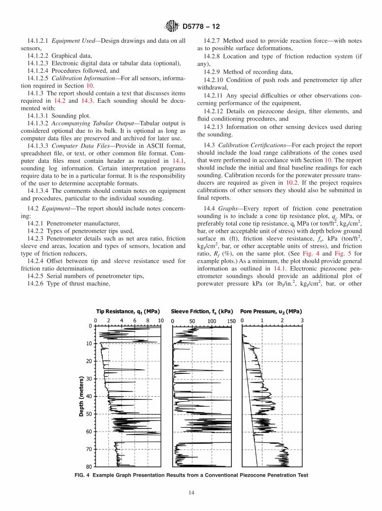
14.4 Graphs—Every report of friction cone penetrationsounding is to include a cone tip resistance plot, qc MPa, orpreferably total cone tip resistance, qt MPa (or ton/ft2, kgf/cm2,bar, or other acceptable unit of stress) with depth below groundsurface m (ft), friction sleeve resistance, fs, kPa (ton/ft2,kgf/cm2, bar, or other acceptable units of stress), and frictionratio, Rf (%), on the same plot. (See Fig. 4 and Fig. 5 forexample plots.) As a minimum, the plot should provide generalinformation as outlined in 14.1. Electronic piezocone pen-etrometer soundings should provide an additional plot ofporewater pressure kPa (or lbf/in.2, kgf/cm2, bar, or other
FIG. 4 Example Graph Presentation Results from a Conventional Piezocone Penetration Test
D5778 − 12
14

acceptable units of pressure) versus depth, m (ft). Porewaterreadings can be plotted as pressures, or alternatively, thepressure may be converted to equivalent heights of water (thatis, hw = u2/γw).
14.4.1 Symbols qt and fs for tip and sleeve resistance areaccepted by the International Society for Soil Mechanics andGeotechnical Engineering (4, 1, 5, 9).
14.4.2 For uniform presentation of data, the vertical axis(ordinate) should display depth and the horizontal axis (ab-scissa) should display the test values. There are many prefer-ences in plotting such that uniform plotting scales and presen-tation will not be required.
15. Precision and Bias
15.1 Precision—There are little direct data on the precisionof this test method, in particular because of the naturalvariability of the ground. Committee D-18 is actively seekingcomparative studies. Judging from observed repeatability inapproximate uniform deposits, persons familiar with this testestimate its precision as follows:
15.1.1 Cone Resistance—Provided that compensation ismade for unequal area effects as described in 13.2.1, a standarddeviation of approximately 2 % FSO (that is, comparable to thebasic electromechanical combined accuracy, nonlinearity, andhysteresis).
15.1.2 Sleeve Friction—Subtraction Cones—Standard de-viation of 15 % FSO.
15.1.3 Sleeve Friction—Independent Cones—Standard de-viation of 5 % FSO.
15.1.4 Dynamic Porewater Pressure—Strongly dependentupon operational procedures and adequacy of saturation asdescribed in 11.2. When carefully carried out a standarddeviation of 2 % FSO can be obtained.
15.2 Bias—This test method has no bias because the valuesdetermined can be defined only in terms of this test method.
NOTE 13—Jefferies and Davies (14) report qt repeatability of the twodifferent soundings in compact clean sand using two different cones by thesame manufacturer. Approximately 50 % of the data lay within 8 % of theaverage of the two tests, and 90 % of the data lay within 15 % of theaverage. In this trial the transducers (that conformed to the requirementsin A1.5) were loaded to between one tenth and one fifth of their rated FSO,so confirming a standard deviation of better than 2 % FSO.
16. Keywords
16.1 cone penetration test; cone penetrometer; explorations;field test; friction resistance; geotechnical test; in-situ testing;penetration tests; penetrometer; piezocone; point resistance;porewater pressures; resistance; sleeve friction; soil investiga-tions
FIG. 5 Illustrative Piezocone Graph Showing Tip Resistance, Sleeve Friction, Penetration Porewater Pressure, and Friction Ratio
D5778 − 12
15

ANNEX
(Mandatory Information)
A1. CALIBRATION REQUIREMENTS ON NEWLY MANUFACTURED OR REPAIRED ELECTRONIC FRICTION CONE ANDPIEZOCONE PENETROMETERS
A1.1 Introduction:
A1.1.1 This annex describes procedures and requirementsfor calibrating electronic cone penetrometers. The evaluationof cone penetrometer calibration as described in this annex isa quality assurance standard for newly manufactured andrepaired penetrometer tips. Many of the standards may beimpractical to evaluate under field operating conditions.Therefore, determination of these calibration errors for anyindividual penetrometer tip should be performed in a labora-tory environment under ideal conditions by the manufacturer orother qualified personnel with necessary knowledge,experience, and facilities.
A1.1.2 The electronic cone penetrometer is a delicate in-strument subjected to severe field conditions. Proper use ofsuch an instrument requires detailed calibration after manufac-ture and continuous field calibrations. Years of cone penetrom-eter design and performance experience have resulted inrefined cone designs and calibration procedures which makethe electronic cone penetrometer a highly reliable instrument.Reports of these experiences form the basis for requirements inthis annex (3, 4, 1, 5, 11, 12).
A1.1.3 The required calibration tolerances developed in thisannex are based on subtraction type electronic cone penetrom-eters. These penetrometers are more robust than electroniccone penetrometers with independent tip and sleeve load cellsand are the most widely used design. The subtraction typepenetrometer, however, has less precision due to the subtrac-tion process (5, 11). As a result, calibration tolerances givenhere are considered maximum values and requirements formore sensitive cone penetrometers imply smaller toleranceshaving greater precision. The calibration process consists ofloading the penetrometer tip with reference forces and pres-sures and then comparing measured output to the reference.
A1.1.4 Calibrations in the laboratory environment should beperformed with the complete penetrometer system to be used inthe field. The same make and model computer, cable, signalconditioning system, and penetrometer to be used in the fieldshall be calibrated in the laboratory. Depending on the com-ponents of the system some components may be substitutedwith acceptable replacements. Each individual penetrometermust be tested over a range of loads to assure adequateperformance.
A1.2 Terms Related to Force Transducer Calibrations:
A1.2.1 Fig. A1.1 is a graphical depiction of terms related totransducer calibrations and defines the concepts of zero-loaderror, nonlinearity, hysteresis, and calibration error (3, 1, 10).
A1.2.2 To evaluate several of these values, the FSO (fullscale output) of the penetrometer tip is needed. The manufac-turer shall provide full scale output information for the system.
Cone penetrometer tips usually are available in nominalcapacities of 2, 5, 10, and 15 metric tons. Typical full-scaleoutputs for these penetrometer tip ranges as follows:
NominalCapacity
Full-Scale Outputof Cone, qc
Full-Scale Outputof
Friction Sleeve, fsmetric tons ton/
ft2MPa ton/ft2 kPa
2 200 20 2 2005 500 50 5 500
10 1000 100 10 100015 1000 100 10 1000
A1.2.3 It is important to check with the manufacturer on thefull scale output of electronic cone penetrometer tips to avoidoverloading and damaging penetrometer tips.
A1.3 Zero Load Baseline Values:
A1.3.1 Zero-load output variation of the cone penetrometerduring testing and calibration is a reliable indicator of outputstability, internal O-ring friction, and temperature-inducedapparent load. The variation in zero load output is affected bytemperature fluctuation because temperature compensatedstrain gages do not compensate for material effects and systemcomponent effects (3, 4, 1, 5, 10).
A1.3.2 Systems with microprocessors provide “referencebaseline” values for the transducers that are not equal to zerobut are measured positive or negative values depending on theelectronics of the system. For the particular penetrometer and
FIG. A1.1 Definition of Calibration Terms for Load Cells andTransducers (1, 10)
D5778 − 12
16
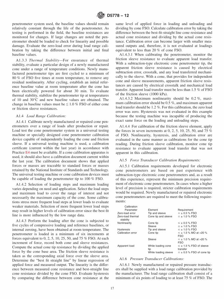
penetrometer system used, the baseline values should remainrelatively constant through the life of the penetrometer. Astesting is performed in the field, the baseline resistances aremonitored for changes. If large changes are noted the pen-etrometer should be loaded to check for linearity and possibledamage. Evaluate the zero-load error during load range cali-bration by taking the difference between initial and finalbaseline values.
A1.3.3 Thermal Stability—For ensurance of thermalstability, evaluate a particular design of a newly manufacturedcone under a range of temperature conditions. Newly manu-factured penetrometer tips are first cycled to a minimum of80 % of FSO five times at room temperature, to remove anyresidual nonlinearity. After cycling, establish an initial refer-ence baseline value at room temperature after the cone hasbeen electrically powered for about 30 min. To evaluatethermal stability, stabilize the penetrometer tip at temperaturesof 10 and 30°C and new baseline values are obtained. Thechange in baseline values must be ≤ 1.0 % FSO of either coneor friction sleeve resistances.
A1.4 Load Range Calibration:
A1.4.1 Calibrate newly manufactured or repaired cone pen-etrometers over a range of loads after production or repair.Load test the cone penetrometer system in a universal testingmachine or specially designed cone penetrometer calibrationdevice capable of independently loading the cone and frictionsleeve. If a universal testing machine is used, a calibrationcertificate (current within the last year) in accordance withPractice E4 must be available. If a cone calibration apparatus isused, it should also have a calibration document current withinthe last year. The calibration document shows that appliedforces or masses are traceable to standard forces or massesretained by the National Institute of Standards and Technology.The universal testing machine or cone calibration devices mustbe capable of loading the penetrometer tip to 100 % FSO.
A1.4.2 Selection of loading steps and maximum loadingvaries depending on need and application. Select the load stepsand maximum load to cover the range of interest and notnecessarily the maximum capacity of the cone. Some calibra-tions stress more frequent load steps at lower loads to evaluateweaker materials. Selection of more frequent lower load stepsmay result in higher levels of calibration error since the best fitline is more influenced by the low range data.
A1.4.3 Perform the loading after the cone is subjected tofive cycles of compressive loading and reference baselines, orinternal zeroing, have been obtained at room temperature. Thepenetrometer is loaded in a minimum of six increments atforces equivalent to 0, 2, 5, 10, 25, 50, and 75 % FSO. At eachincrement of force, record both cone and sleeve resistances.Compute the actual cone tip resistance by dividing the appliedforce by the cone base area. The friction sleeve resistance istaken as the corresponding axial force over the sleeve area.Determine the “best fit straight line” by linear regression ofapplied force and measured output. The linearity is the differ-ence between measured cone resistance and best-straight linecone resistance divided by the cone FSO. Evaluate hysteresisby comparing the difference between cone resistance at the
same level of applied force in loading and unloading anddividing by cone FSO. Calculate calibration error by taking thedifference between the best-fit-straight line cone resistance andactual cone resistance and dividing by the actual cone resis-tance. Calibration error can become larger with smaller mea-sured outputs and, therefore, it is not evaluated at loadingsequivalent to less than 20 % of cone FSO.
A1.4.3.1 When calibrating the penetrometer, monitor thefriction sleeve resistance to evaluate apparent load transfer.With a subtraction-type electronic cone penetrometer tip, theapparent friction sleeve resistance is caused by electricalsubtraction error, crosstalk, and any load transferred mechani-cally to the sleeve. With a cone, that provides for independentcone and sleeve measurements, apparent friction sleeve resis-tances are caused by electrical crosstalk and mechanical loadtransfer. Apparent load transfer must be less than 1.5 % of FSOof the friction sleeve (1000 kPa).
A1.4.3.2 Maximum nonlinearity should be 0.2 %, maxi-mum calibration error should be 0.5 %, and maximum apparentload transfer should be 1.2 %. For this calibration, the zero loaderror was zero. Hysteresis was not evaluated in this examplebecause the testing machine was incapable of producing theexact same force on the loading and unloading steps.
A1.4.4 For calibration of the friction sleeve element, applythe forces in seven increments at 0, 2, 5, 10, 25, 50, and 75 %of FSO. Nonlinearity, hysteresis, and calibration error areevaluated in the same manner as calibrations for the cone tipreading. During friction sleeve calibration, monitor cone tipresistance to evaluate apparent load transfer that was notapparent in this calibration.
A1.5 Force Transducer Calibration Requirements:
A1.5.1 Calibration requirements developed for electroniccone penetrometers are based on past experience withsubtraction-type electronic cone penetrometers and, as a resultof this experience, represent the minimum precision require-ment of electronic cone penetrometers. In cases where a higherlevel of precision is required, stricter calibration requirementswould be required. Newly manufactured or repaired electroniccone penetrometers are required to meet the following require-ments:
CalibrationParameter Element Requirement
Zero-load error Tip and sleeve # ± 0.5 % FSOZero-load thermal
stabilityCone tip and sleeve # ± 1.0 % FSO
Nonlinearity Cone tip # ± 0.5 % FSOSleeve # ± 1.0 % FSO
Hysteresis Tip and sleeve # ± 1.0 % FSOCalibration error Cone tip # ± 1.5 % MO at >20 %
FSOSleeve # ± 1.0 % MO at >20 %
FSOApparent load While loading cone
tip# ± 1.5 % FSO of sleevetransfer
While loading sleeve # ± 0.5 % FSO of cone tip
A1.6 Pressure Transducer Calibrations:
A1.6.1 Newly manufactured or repaired pressure transduc-ers shall be supplied with a load range calibration provided bythe manufacturer. The load range calibration shall consist of aminimum of six points of loading to at least 75 % of FSO. The
D5778 − 12
17
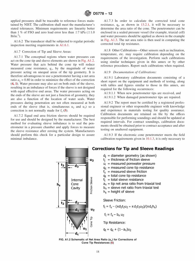
applied pressures shall be traceable to reference forces main-tained by NIST. The calibration shall meet the manufacturer’sstated tolerances. Minimum requirements are linearity betterthan 1 % of FSO and zero load error less than 67 kPa (61.0lb/in.2).
A1.6.2 The transducer shall be subjected to regular periodicinspection meeting requirements in A1.6.1.
A1.7 Correction of Tip and Sleeve Areas:
A1.7.1 The conceptual regions where water pressures canact on the cone tip and sleeve elements are shown in Fig. A1.2.Water pressure that acts behind the cone tip will reducemeasured cone resistance, qc, by the magnitude of waterpressure acting on unequal areas of the tip geometry. It istherefore advantageous to use a penetrometer having a net arearatio an = 0.80 in order to minimize the effect of the correction(4, 1). Water pressure may also act on both ends of the sleeve,resulting in an imbalance of forces if the sleeve is not designedwith equal effective end areas. The water pressures acting onthe ends of the sleeve are not just a function of geometry, theyare also a function of the location of water seals. Waterpressures during penetration are not often measured at bothends of the sleeve (that is, simultaneous u2 and u3) so acorrection is not normally made for fs (5).
A1.7.2 Equal end area friction sleeves should be requiredfor use and should be designed by the manufacturer. The bestmethod for evaluating sleeve imbalance is to seal the pen-etrometer in a pressure chamber and apply forces to measurethe sleeve resistance after zeroing the system. Manufacturersshould perform this check for a particular design to assureminimal imbalance.
A1.7.3 In order to calculate the corrected total coneresistance, qt, as shown in 13.2.1, it will be necessary todetermine the area ratio of the cone. The penetrometer can beenclosed in a sealed pressure vessel (for example, triaxial cell)and water pressures should be applied as shown in the examplein Fig. A1.3. The net area ratio is then used in computing thecorrected total tip resistance.
A1.8 Other Calibrations—Other sensors such as inclination,temperature, etc. may require calibration depending on therequirements of the investigation. Perform such calibrationsusing similar techniques given in this annex or by otherreference procedures. Report such calibrations when required.
A1.9 Documentation of Calibrations:
A1.9.1 Laboratory calibration documents consisting of ashort report on the equipment and methods of testing, alongwith tables and figures similar to those in this annex, arerequired for the following occurrences:
A1.9.1.1 When new penetrometer tips are received, andA1.9.1.2 When damaged penetrometer tips are repaired.
A1.9.2 The report must be certified by a registered profes-sional engineer or other responsible engineer with knowledgeand experience in materials testing for quality assurance.Calibration documents are retained on file by the officesresponsible for performing soundings and should be updated atrequired intervals. For contract soundings, calibration docu-ments should be obtained prior to contract acceptance and aftertesting on unaltered equipment.
A1.9.3 If the electronic cone penetrometer meets the fieldcalibration requirements given in 10.1.3, it is only necessary to
FIG. A1.2 Schematic of Net Area Ratio (an) for Corrections ofCone Tip Resistances (6)
D5778 − 12
18
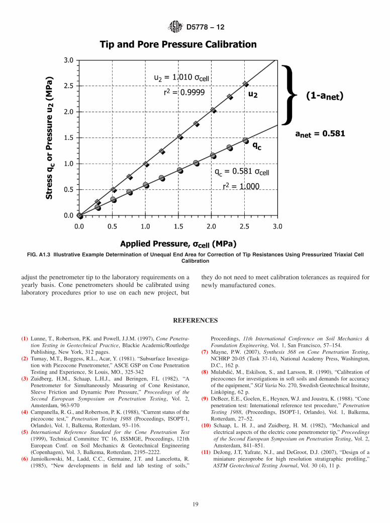
adjust the penetrometer tip to the laboratory requirements on ayearly basis. Cone penetrometers should be calibrated usinglaboratory procedures prior to use on each new project, but
they do not need to meet calibration tolerances as required fornewly manufactured cones.
REFERENCES
(1) Lunne, T., Robertson, P.K. and Powell, J.J.M. (1997), Cone Penetra-tion Testing in Geotechnical Practice, Blackie Academic/RoutledgePublishing, New York, 312 pages.
(2) Tumay, M.T., Boggess, R.L., Acar, Y. (1981). “Subsurface Investiga-tion with Piezocone Penetrometer,” ASCE GSP on Cone PenetrationTesting and Experience, St Louis, MO., 325-342
(3) Zuidberg, H.M., Schaap, L.H.J., and Beringen, F.L (1982). “APenetrometer for Simultaneously Measuring of Cone Resistance,Sleeve Friction and Dynamic Pore Pressure,” Proceedings of theSecond European Symposium on Penetration Testing, Vol. 2,Amsterdam, 963-970
(4) Campanella, R. G., and Robertson, P. K. (1988), “Current status of thepiezocone test,” Penetration Testing 1988 (Proceedings, ISOPT-1,Orlando), Vol. 1, Balkema, Rotterdam, 93–116.
(5) International Reference Standard for the Cone Penetration Test(1999), Technical Committee TC 16, ISSMGE, Proceedings, 121thEuropean Conf. on Soil Mechanics & Geotechnical Engineering(Copenhagen), Vol. 3, Balkema, Rotterdam, 2195–2222.
(6) Jamiolkowski, M., Ladd, C.C., Germaine, J.T. and Lancelotta, R.(1985), “New developments in field and lab testing of soils,”
Proceedings, 11th International Conference on Soil Mechanics &Foundation Engineering, Vol. 1, San Francisco, 57–154.
(7) Mayne, P.W. (2007), Synthesis 368 on Cone Penetration Testing,NCHRP 20-05 (Task 37-14), National Academy Press, Washington,D.C., 162 p.
(8) Mulabdić, M., Eskilson, S., and Larsson, R. (1990), “Calibration ofpiezocones for investigations in soft soils and demands for accuracyof the equipment,” SGI Varia No. 270, Swedish Geotechnical Insitute,Linköping, 62 p.
(9) DeBeer, E.E., Goelen, E., Heynen, W.J. and Joustra, K. (1988). “Conepenetration test: International reference test procedure,” PenetrationTesting 1988, (Proceedings, ISOPT-1, Orlando), Vol. 1, Balkema,Rotterdam, 27–52.
(10) Schaap, L. H. J., and Zuidberg, H. M. (1982), “Mechanical andelectrical aspects of the electric cone penetrometer tip,” Proceedingsof the Second European Symposium on Penetration Testing, Vol. 2,Amsterdam, 841–851.
(11) DeJong, J.T, Yafrate, N.J., and DeGroot, D.J. (2007), “Design of aminiature piezoprobe for high resolution stratigraphic profiling,”ASTM Geotechnical Testing Journal, Vol. 30 (4), 11 p.
FIG. A1.3 Illustrative Example Determination of Unequal End Area for Correction of Tip Resistances Using Pressurized Triaxial CellCalibration
D5778 − 12
19

(12) De Ruiter, J. (1982). “The Static Cone Penetration Test: State-of-the-Art Report,” Proceedings of the Second European Symposium onPenetration Testing, Vol. 2, Amsterdam, 389-405.
(13) Lutenegger, A.J. and DeGroot, D.J. (1995), “Techniques for sealingcone penetrometer holes,” Canadian Geotechnical Journal, Vol. 32(5), 880–891.
(14) Jefferies, M. G., and Davies, M. P. (1993), “Use of the CPTu toEstimate Equivalent SPT N60,” Geotechnical Testing Journal, Vol.16, No. 4, ASTM, 458–468.
SUMMARY OF CHANGES
Committee D18 has identified the location of selected changes to this test method since the last issue,D5778–07 that may impact the use of test method. (Approved January 1, 2012)
(1) Added reference to Test Methods D7400.(2) Clarification of definition 3.2.10 electronic piezoconepenetrometer.(3) Added new references and corrected reference numbers intext for these changes.(4) Corrected Eq 8.(5) Corrected definition of symbols used in Eq 7, Eq 8, and Eq9.
(6) Added Note 2 and Note 3 and renumbered subsequentnotes.(7) Added reference to Note 2 in 13.4.(8) Deleted terms hydrostatic pressure, hydrostatic porewaterpressure, and reference to Terminology D653 in 3.2.10 and13.5.3.
ASTM International takes no position respecting the validity of any patent rights asserted in connection with any item mentionedin this standard. Users of this standard are expressly advised that determination of the validity of any such patent rights, and the riskof infringement of such rights, are entirely their own responsibility.
This standard is subject to revision at any time by the responsible technical committee and must be reviewed every five years andif not revised, either reapproved or withdrawn. Your comments are invited either for revision of this standard or for additional standardsand should be addressed to ASTM International Headquarters. Your comments will receive careful consideration at a meeting of theresponsible technical committee, which you may attend. If you feel that your comments have not received a fair hearing you shouldmake your views known to the ASTM Committee on Standards, at the address shown below.
This standard is copyrighted by ASTM International, 100 Barr Harbor Drive, PO Box C700, West Conshohocken, PA 19428-2959,United States. Individual reprints (single or multiple copies) of this standard may be obtained by contacting ASTM at the aboveaddress or at 610-832-9585 (phone), 610-832-9555 (fax), or [email protected] (e-mail); or through the ASTM website(www.astm.org). Permission rights to photocopy the standard may also be secured from the Copyright Clearance Center, 222Rosewood Drive, Danvers, MA 01923, Tel: (978) 646-2600; http://www.copyright.com/
D5778 − 12
20